EP3246218B1 - Elektromagnetventil - Google Patents
Elektromagnetventil Download PDFInfo
- Publication number
- EP3246218B1 EP3246218B1 EP17001090.4A EP17001090A EP3246218B1 EP 3246218 B1 EP3246218 B1 EP 3246218B1 EP 17001090 A EP17001090 A EP 17001090A EP 3246218 B1 EP3246218 B1 EP 3246218B1
- Authority
- EP
- European Patent Office
- Prior art keywords
- valve
- poppet
- cage
- armature
- valve body
- Prior art date
- Legal status (The legal status is an assumption and is not a legal conclusion. Google has not performed a legal analysis and makes no representation as to the accuracy of the status listed.)
- Active
Links
Images


Classifications
-
- F—MECHANICAL ENGINEERING; LIGHTING; HEATING; WEAPONS; BLASTING
- F16—ENGINEERING ELEMENTS AND UNITS; GENERAL MEASURES FOR PRODUCING AND MAINTAINING EFFECTIVE FUNCTIONING OF MACHINES OR INSTALLATIONS; THERMAL INSULATION IN GENERAL
- F16K—VALVES; TAPS; COCKS; ACTUATING-FLOATS; DEVICES FOR VENTING OR AERATING
- F16K27/00—Construction of housing; Use of materials therefor
- F16K27/02—Construction of housing; Use of materials therefor of lift valves
- F16K27/0245—Construction of housing; Use of materials therefor of lift valves with ball-shaped valve members
-
- B—PERFORMING OPERATIONS; TRANSPORTING
- B60—VEHICLES IN GENERAL
- B60T—VEHICLE BRAKE CONTROL SYSTEMS OR PARTS THEREOF; BRAKE CONTROL SYSTEMS OR PARTS THEREOF, IN GENERAL; ARRANGEMENT OF BRAKING ELEMENTS ON VEHICLES IN GENERAL; PORTABLE DEVICES FOR PREVENTING UNWANTED MOVEMENT OF VEHICLES; VEHICLE MODIFICATIONS TO FACILITATE COOLING OF BRAKES
- B60T8/00—Arrangements for adjusting wheel-braking force to meet varying vehicular or ground-surface conditions, e.g. limiting or varying distribution of braking force
- B60T8/32—Arrangements for adjusting wheel-braking force to meet varying vehicular or ground-surface conditions, e.g. limiting or varying distribution of braking force responsive to a speed condition, e.g. acceleration or deceleration
- B60T8/34—Arrangements for adjusting wheel-braking force to meet varying vehicular or ground-surface conditions, e.g. limiting or varying distribution of braking force responsive to a speed condition, e.g. acceleration or deceleration having a fluid pressure regulator responsive to a speed condition
- B60T8/36—Arrangements for adjusting wheel-braking force to meet varying vehicular or ground-surface conditions, e.g. limiting or varying distribution of braking force responsive to a speed condition, e.g. acceleration or deceleration having a fluid pressure regulator responsive to a speed condition including a pilot valve responding to an electromagnetic force
- B60T8/3615—Electromagnetic valves specially adapted for anti-lock brake and traction control systems
- B60T8/363—Electromagnetic valves specially adapted for anti-lock brake and traction control systems in hydraulic systems
-
- F—MECHANICAL ENGINEERING; LIGHTING; HEATING; WEAPONS; BLASTING
- F16—ENGINEERING ELEMENTS AND UNITS; GENERAL MEASURES FOR PRODUCING AND MAINTAINING EFFECTIVE FUNCTIONING OF MACHINES OR INSTALLATIONS; THERMAL INSULATION IN GENERAL
- F16K—VALVES; TAPS; COCKS; ACTUATING-FLOATS; DEVICES FOR VENTING OR AERATING
- F16K27/00—Construction of housing; Use of materials therefor
- F16K27/02—Construction of housing; Use of materials therefor of lift valves
- F16K27/029—Electromagnetically actuated valves
-
- F—MECHANICAL ENGINEERING; LIGHTING; HEATING; WEAPONS; BLASTING
- F16—ENGINEERING ELEMENTS AND UNITS; GENERAL MEASURES FOR PRODUCING AND MAINTAINING EFFECTIVE FUNCTIONING OF MACHINES OR INSTALLATIONS; THERMAL INSULATION IN GENERAL
- F16K—VALVES; TAPS; COCKS; ACTUATING-FLOATS; DEVICES FOR VENTING OR AERATING
- F16K31/00—Actuating devices; Operating means; Releasing devices
- F16K31/02—Actuating devices; Operating means; Releasing devices electric; magnetic
- F16K31/06—Actuating devices; Operating means; Releasing devices electric; magnetic using a magnet, e.g. diaphragm valves, cutting off by means of a liquid
- F16K31/0644—One-way valve
- F16K31/0655—Lift valves
- F16K31/0665—Lift valves with valve member being at least partially ball-shaped
-
- B—PERFORMING OPERATIONS; TRANSPORTING
- B60—VEHICLES IN GENERAL
- B60T—VEHICLE BRAKE CONTROL SYSTEMS OR PARTS THEREOF; BRAKE CONTROL SYSTEMS OR PARTS THEREOF, IN GENERAL; ARRANGEMENT OF BRAKING ELEMENTS ON VEHICLES IN GENERAL; PORTABLE DEVICES FOR PREVENTING UNWANTED MOVEMENT OF VEHICLES; VEHICLE MODIFICATIONS TO FACILITATE COOLING OF BRAKES
- B60T8/00—Arrangements for adjusting wheel-braking force to meet varying vehicular or ground-surface conditions, e.g. limiting or varying distribution of braking force
- B60T8/32—Arrangements for adjusting wheel-braking force to meet varying vehicular or ground-surface conditions, e.g. limiting or varying distribution of braking force responsive to a speed condition, e.g. acceleration or deceleration
- B60T8/34—Arrangements for adjusting wheel-braking force to meet varying vehicular or ground-surface conditions, e.g. limiting or varying distribution of braking force responsive to a speed condition, e.g. acceleration or deceleration having a fluid pressure regulator responsive to a speed condition
- B60T8/48—Arrangements for adjusting wheel-braking force to meet varying vehicular or ground-surface conditions, e.g. limiting or varying distribution of braking force responsive to a speed condition, e.g. acceleration or deceleration having a fluid pressure regulator responsive to a speed condition connecting the brake actuator to an alternative or additional source of fluid pressure, e.g. traction control systems
- B60T8/4809—Traction control, stability control, using both the wheel brakes and other automatic braking systems
- B60T8/4827—Traction control, stability control, using both the wheel brakes and other automatic braking systems in hydraulic brake systems
- B60T8/4863—Traction control, stability control, using both the wheel brakes and other automatic braking systems in hydraulic brake systems closed systems
- B60T8/4872—Traction control, stability control, using both the wheel brakes and other automatic braking systems in hydraulic brake systems closed systems pump-back systems
Definitions
- control valve Various embodiments of a control valve are described herein.
- the embodiments described herein are mounted in a hydraulic control unit of an electronically controlled brake system.
- One type of electronically controlled brake system includes a hydraulic control unit (HCU) connected in fluid communication between a master cylinder and a plurality of wheel brakes.
- the HCU typically includes a housing containing control valves and other components for selectively controlling hydraulic brake pressure at the wheel brakes.
- Control valves for HCU's are commonly formed as electronically actuated solenoid valves.
- a typical solenoid valve includes a cylindrical armature slidably received in a sleeve or flux tube for movement relative to a valve seat.
- a spring is used to bias the armature in an open or closed position, thereby respectively permitting or blocking fluid flow through the valve.
- a coil assembly is provided about the sleeve. When the valve is energized, an electromagnetic field or flux generated by the coil assembly causes the armature to respectively slide from the biased open or closed position to a closed or open position.
- Control valves mounted in a HCU are actuated by an electronic control unit (ECU) to provide desired braking functions such as anti-lock braking, traction control, and vehicle stability control.
- ECU electronice control unit
- an armature To provide desired braking responses, an armature must respond quickly and in a predictable manner to an electromagnetic field generated by an energized coil assembly.
- Document EP 0 997 363 A2 discloses a hydraulic control unit of a vehicular brake system including a housing having a bore formed therein.
- a normally closed solenoid valve is retained in the bore of the housing.
- the solenoid valve includes a primary valve and a pilot valve, wherein a cross section of the primary valve is greater than a cross section of the pilot valve.
- a spring cooperates with the pilot valve so that the pilot valve is open when the primary valve is open.
- WO/0166396 A1 relates to a solenoid valve comprising a first and a second valve closing body that are arranged in a valve housing and capable of opening and closing a first and a second valve gate.
- the valve comprises a hydraulic fluid inlet channel which opens into the valve housing and a hydraulic fluid outlet channel.
- the first valve closing body can open or close the first valve gate that is situated in the second valve closing body and the second valve gate can only be hydraulically actuated into the open position when the first valve closing body is in the open position.
- document US 2008/0197313 A1 discloses an actuator housing including an elongated body having a flange, an end portion and a sealing portion, wherein the elongated body, including the flange, the end portion and the sealing portion, is formed from a single and continuous piece of material.
- the present application describes various embodiments of an electromagnetic valve for use in controlling fluid flow between first and second passageways in a hydraulic valve block.
- One embodiment of the electromagnetic valve includes a valve body.
- the valve body defines a central axis, has a central opening therethrough, has a lower end adapted to be inserted into a bore of the valve block, and is provided with a lower cylindrical opening.
- An armature is axially moveable within the valve body and is spring biased in one axial direction.
- a closing element is carried by a lower end of the armature.
- An electromagnetic coil coaxially surrounds the armature and is operable to effect axial movement of the armature in an axial direction opposite the one direction.
- a valve seat member is carried by the lower end of the valve body and has an orifice providing fluid flow between the first and second valve block passageways.
- the valve seat member defines a valve seat surrounding the orifice and cooperates with the closing element for selectively closing the orifice.
- the valve seat member includes a cylindrical tubular portion frictionally retained in the lower cylindrical opening of the valve body.
- the lower cylindrical opening of the valve body is provided with a stop surface at the upper end of thereof, and an upper part of the cylindrical portion of the valve seat member includes a flange engageable with the stop surface for limiting downward movement of the valve seat member relative to the valve body.
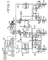
- a hydraulic vehicle brake system is indicated generally at 10 in Fig. 1 .
- the illustrated embodiment of the vehicle brake system 10 includes valves and other components described below to provide an electronic brake control capability.
- the vehicle brake system 10 is intended to be exemplary and it will be appreciated that there are other brake control system configurations that may be used to implement the various valve embodiments described herein.
- the brake system 10 may include components to provide an anti-lock braking, traction control, and/or vehicle stability control function.
- the vehicle brake system 10 has two separate brake circuits 11A and 11B, respectively, which are depicted on the left and right halves of Fig. 1 .
- the circuits supply brake pressure to a front and rear wheel brake.
- the illustrated rear wheel brake is arranged diagonally to the front wheel brake. Only a left brake circuit 11A in Fig. 1 is described in the following in more detail, however a right brake circuit 11B in Fig. 1 is structured in the same manner.
- the brake system 10 includes a driver-controlled first pressure generating unit 12 with a brake pedal 14, a power brake unit 16 and a tandem master brake cylinder 18, which presses the brake fluid out of a reservoir 20 into the two brake circuits 11A and 11B.
- a pressure sensor 22 Arranged behind an outlet of the tandem master brake cylinder 18 is a pressure sensor 22 for detecting the driver's input.
- a brake fluid pressure emanating from the driver-controlled first pressure generating unit 12 continues via the block valve arrangement 24 and an anti-lock brake system (ABS) valve arrangement 26 to wheel brake cylinders 28.
- the ABS valve arrangement 26 includes an ABS inlet or isolation valve 30 and an ABS discharge or dump valve 32.
- the ABS inlet valve 30 is normally open, and the ABS discharge valve 32 is normally closed.
- Each wheel brake cylinder 28 includes an ABS valve arrangement 26 and the brake fluid pressure of both brake circuits is distributed diagonally in the vehicle to a respective pair of wheel brake cylinders 28 (front left (FL) and rear right (RR), or front right (FR) and rear left (RL)), respectively.
- the illustrated block valve arrangement 24 is part of a traction control or vehicle stability control system and includes an isolation valve 25 that is normally open in a currentless state. In a current-carrying state the block valve arrangement 24 is blocked from a backflow of brake fluid from the wheel brake cylinders 28 to the master brake cylinder 18.
- Brake fluid pressure may be built up independent of the driver-controlled first pressure generating unit 12 by an autonomous second pressure generating unit 34.
- the autonomous second pressure generating unit 34 includes a pump 36 driven by a pump motor 39, an attenuator 44, and an orifice 38.
- the attenuator 44 is in fluid communication with a pump outlet 46 and the inlet side 40 of the orifice 38. Pulsations emanating from the pump 36 are periodic fluctuations in the brake fluid flow.
- the attenuator 44 takes in brake fluid during the pulsation peaks and releases it again between the pulsation peaks. As a result, the attenuator 44 levels out a temporal pressure progression on the inlet side 40 of the orifice 38.
- a low pressure accumulator (LPA) 48 and a pump inlet or supply valve 50 Arranged on the intake side of the pump 36 are a low pressure accumulator (LPA) 48 and a pump inlet or supply valve 50.
- the illustrated pump inlet valve 50 is a normally closed valve. When the pump inlet valve 50 is currentless and closed, the pump 36 is supplied with brake fluid from the LPA 48. When the pump inlet valve 50 is current-carrying and open, the pump 36 can also suction brake fluid from the master brake cylinder 18.
- the driver-controlled first pressure generating unit 12 and the autonomous second pressure generating unit 34 convey brake fluid in a common brake branch 52 of one of the two brake circuits.
- both pressure generating units 12, 34 can build up brake fluid pressure to the wheel brake cylinders 28 of the brake circuit independent of one another.
- the vehicle brake system 10 described in the foregoing uses the autonomous second pressure generating unit 34 for generating brake pressure within the scope of a vehicle stability control (VSC function). Moreover, the autonomous second pressure generating unit 34 is also used for the adaptive cruise control (ACC function). In the process, the autonomous second pressure generating unit 34 can build up brake fluid pressure for autonomously braking the vehicle in the course of a stop-and-go function in frequent succession and not just in extraordinary, relatively rare driving situations. This also occurs with predominantly low to moderate driving speeds, at which the basic noise level in the vehicle interior is relatively low. Under such conditions, known pressure generating units represent a source of noise and pulsation that is annoying in terms of driving comfort.
- the vehicle brake system 10 may include a hydraulic valve block or hydraulic control unit (HCU) 4 (not shown in Fig. 1 ) connected in fluid communication between the master brake cylinder 18 and wheel brake cylinders 28.
- HCU hydraulic valve block or hydraulic control unit
- the HCU 4 typically includes a housing 2 containing the various control valves and other components described herein for selectively controlling hydraulic brake pressure at the wheel brake cylinders 28.
- the vehicle brake system 10 may include an electronic control unit (ECU) which receives input signals from sensors, such as yaw rate, master cylinder pressure, lateral acceleration, steer angle, and wheel speed sensors.
- the ECU may also receive ground speed data from the ACC system 56.
- the ACC system may receive input data from a radar and the vehicle yaw rate sensor.
- FIG. 2 A sectional view of an exemplary embodiment of the dump valve 32 is shown in Fig. 2 .
- the dump valve 32 is received in a bore 19 formed in the housing 2.
- the dump valve 32 includes a valve body or sleeve 51 having a first end 52 (the upper end when viewing Fig. 2 ) and a second end 54 (the lower end when viewing Fig. 2 ).
- the sleeve 51 defines a central or longitudinal axis A.
- An armature 56 has a first end 58 and a second end 60 and is slidably received in the sleeve 51.
- the dump valve 32 further includes a valve seat member 62 and a coil assembly 64 disposed about the sleeve 51. Because the dump valve 32 is a normally closed valve, the armature 56 is biased into contact with the valve seat member 62 by a spring 66 when the coil assembly 64 of the dump valve 32 is not energized, thereby blocking fluid flow through the dump valve 32. When the coil assembly 64 is energized, the armature 56 is urged away from the valve seat member 62 to permit fluid flow between a first passageway P1 and a second passageway P2 and through the dump valve 32, as indicated by the arrows 29.
- the sleeve 51 has a central opening 51A therethrough and is formed as a single piece from non-ferromagnetic material in a deep drawing process.
- suitable ferromagnetic material is stainless steel. It will be understood however, that low-carbon steel is not required, and that the sleeve 51 may be formed from any other desired non-ferromagnetic material.
- the first end 52 of the sleeve 51 defines an axially extending cylindrical portion.
- the second end 54 of the sleeve 51 includes a radially inwardly extending wall which defines a stop surface or shoulder 68.
- the shoulder 68 further defines a lower cylindrical or sleeve opening 70.
- the opening 70 includes an axially extending cylindrical portion 72.
- the shoulder 68 has at least one fluid flow aperture 74 formed therein.
- a substantially cylindrical mounting collar 76 is attached, such as by welding, about an outer surface of the second end 54 of the sleeve 51.
- the illustrated collar 76 includes a radially outwardly extending circumferential flange 78 at one end (the lower end when viewing Fig. 2 ).
- a magnetic core 82 is attached within the first end 52 of the sleeve 51, thereby closing the first end 52 of the sleeve 51.
- the core 82 may be attached to the first end 52 of the sleeve 51 by any suitable means, such as with a single laser weld. Alternatively, the core 82 may be attached to the first end 52 of the sleeve 51 by any other desired method.
- the armature 56 is slidably received in the first end 52 of the sleeve 51.
- the first end 58 of the armature 56 includes a spring cavity 84.
- the spring 66 is disposed in the cavity 84 and engages the armature 56 and the core 82 to urge the armature 56 toward the valve seat member 62 (in the direction of the arrow 57A) when the dump valve 32 is in the closed position.
- the armature 56 moves away from the valve seat member 62 (in the direction of the arrow 57B) such that the armature 56 is disposed at an extreme of travel away from the valve seat member 62, and is in an open position (not illustrated).
- a substantially cylindrical recess 86 is formed in an end surface of the second end 60.
- a spherical closing element or ball 88 is pressed into the recess 86.
- the ball 88 is formed from steel.
- the ball 88 may be formed from any other substantially non-deformable metal or non-metal.
- the ball 88 acts as a valve sealing element and engages the valve seat member 62 when the valve 32 is in the closed position (e.g. when the coil assembly 64 is not energized, as shown in Fig. 2 ). It will be understood that the ball 88 is not required, and that a valve sealing element may be integrally formed in the armature 56 at the second end 60 of the armature 56.
- the armature 56 is formed from ferromagnetic material in a cold forming process.
- suitable ferromagnetic material is low-carbon steel. It will be understood however, that low-carbon steel is not required, and that the armature 56 may be formed from any other desired ferromagnetic material.
- the valve seat member 62 includes a generally cylindrical tubular portion or body 90, an upper part or first end 92, and a lower part or second end 94.
- the first end 92 defines a valve seat 96 surrounding an orifice or opening 98.
- a radially outwardly extending circumferential flange 100 is formed at the first end 92 adjacent the valve seat 96.
- the valve seat 96 includes a circumferential ridge 96A surrounding the opening 98.
- the illustrated ridge 96A has a substantially rounded or toroidal surface contour such that the ball 88 sealingly engages the ridge 96A when the dump valve 32 is in the closed position.
- the valve seat member 62 is formed as a single piece from non-ferromagnetic material in a deep drawing process.
- suitable non-ferromagnetic material is stainless steel. It will be understood however, that stainless steel is not required, and that the valve seat member 62 may be formed from any other desired non-ferromagnetic material.
- the valve seat member 62 is widened at a distance from the first end 92 to define the flange 100.
- the illustrated flange 100 includes a crease defined between two substantially transversely extending wall portions 110 and 112. The wall portions 110 and 112 bear against one another substantially without any space between them.
- the body 90 may be press-fit within the cylindrical portion 72 of the sleeve opening 70, such that the body 90 engages the lower cylindrical portion 72 of the sleeve 51.
- the coil assembly 64 is disposed about the sleeve 51, armature 56, and magnetic core 82 and selectively induces a magnetic flux in the armature 56.
- a circumferentially extending internal band filter 104 may be placed about the body 90 of the valve seat member 62, although such a band filter 104 is not required.
- the inner surface of the filter 104 seals against the outer surface of the body 90 of the valve seat member 62.
- a return flow path is defined between the outer surface of the filter 104 and the wall of the bore 19 and between the outer surface of the body 90 of the valve seat member 62 and the wall of the bore 19.
- the bore 19 includes a lip seal groove portion 3. As shown in Fig. 2 , the lip seal groove portion 3 is formed in a frusto-conical manner, as best described in WIPO Publication No. WO/2008/097534 .
- a lip seal 106 is disposed about the body 90 at the second end 94 of the valve seat member 62.
- the illustrated lip seal 106 is substantially V-shaped in transverse section, and includes a resilient annular body 106A.
- a resilient annular seal lip 106B includes an outer circumferential surface and flares radially outwardly and upwardly from the body 106A in the general direction of the valve seat member 62.
- the sleeve 51 is disposed within the bore 19 of the housing 2 such that the flange 78 is supported on a shoulder portion 23 of the bore 19.
- the flange 78 of the collar 76 and therefore the dump valve 32 to which the collar 76 is attached, is retained and sealed within the bore 19 by clinching, wherein material of the housing 2 is forced into engagement with a first surface (an upwardly facing surface when viewing Fig. 2 ) of the flange 78.
- the collar 76 of the may also be retained in the bore 19 by any desired mechanical means operative to retain the dump valve 32 within the bore 19.
- a sectional view of an exemplary embodiment of the supply valve is indicated generally at 50 in Fig. 3 .
- the supply valve 50 is received in a bore 5 formed in the housing 2 and controls fluid flow between a first passageway P1 and a second passageway P2.
- the supply valve 50 includes a valve body or sleeve 200 having a first end 202 (upper end when viewing Fig. 3 ) and a second end 204 (lower end when viewing Fig. 3 ) and defining a central axis B.
- An armature 206 has a first or upper end 208 and a second or lower end 210 and is slidably received in the sleeve 200.
- the supply valve 50 further includes a coil assembly (not shown) disposed about the sleeve 200.
- the sleeve 200 has a central opening 201 therethrough and is formed as a single piece from non-ferromagnetic material in a deep drawing process.
- suitable non-ferromagnetic material is stainless steel. It will be understood however, that stainless steel is not required, and that the sleeve 200 may be formed from any other desired non-ferromagnetic material.
- the sleeve 200 includes a first or upper body portion 212 having a first diameter, a second or intermediate body portion 214 having a second diameter, and a third or lower body portion 216 having a third diameter.
- the second end 204 of the sleeve 200 includes a radially inwardly extending first shoulder 218 extending between the second body portion 214 and the third body portion 216, and defining a valve seat 218.
- the second end 204 further defines a lower cylindrical opening 207.
- a plurality of fluid passages 205 are formed in the sleeve 200.
- a core 220 is attached to the first end of the sleeve 200, thereby closing the first end 202 of the sleeve 200.
- the core 220 is pressed into the sleeve 200 with an interference fit.
- the core 220 may be further hydraulically sealed to the first end 202 of the sleeve 200 by any suitable means, such as with a single laser weld.
- the core 220 may be sealed to the first end 202 of the sleeve 200 by any other desired method.
- the core 220 is formed from ferromagnetic material, such as low carbon steel.
- the armature 206 is slidably received in the sleeve 200.
- the first end 208 of the armature 206 includes a spring cavity 222.
- the first spring 224 is disposed in the cavity 222 and engages the armature 206 and the core 220 to urge the armature 206 and the poppet 226 (described in detail below) toward the valve seat 218 (in the direction of the arrow 57A) when the supply valve 50 is in the closed position.
- the coil assembly represented by the phantom line 64', is energized, the armature 206 and the poppet 226 are disposed at an extreme of travel away from the valve seat 218, such that the supply valve 50 is in an open position (not shown).
- a recess 228 is formed in an end surface of the second end 210 of the armature 206.
- a closing element or ball 230 is pressed into the recess 228.
- the ball 230 is formed from steel.
- the ball 230 may be formed from any other substantially non-deformable metal or non-metal.
- the armature 206 is formed from ferromagnetic material in a cold forming process.
- suitable ferromagnetic material is low-carbon steel. It will be understood however, that low-carbon steel is not required, and that the armature 206 may be formed from any other desired ferromagnetic material.
- the poppet 226 is disposed between the armature 206 and the valve seat 218 and includes a generally cylindrical body 232 having a first end 234 (upper end when viewing Fig. 3 ), a second end 236 (lower end when viewing Fig. 3 ), and a bore 238 therethrough.
- the first end 234 defines a seat portion 240.
- a radially outwardly extending circumferential shoulder 242 is defined in an outer surface of the poppet 226 intermediate the first end 234 and the second end 236.
- a second spring 244 extends between the second end 210 of the armature 206 and the shoulder 242.
- a radially outwardly extending circumferential flange 245 is also formed in an outer surface of the poppet 226.
- the poppet 226 is formed as a single piece from plastic material.
- plastic material is polyether ether ketone (PEEK).
- PEEK polyether ether ketone
- the poppet 226 may be formed from nylon, such as nylon 136. It will be understood that the poppet 226 may also be formed from any other desired material.
- a substantially cup-shaped cage 246 includes a first end 248 (upper end when viewing Fig. 3 ), a second end 250 (lower end when viewing Fig. 3 ), and a central opening 251 formed therethrough.
- the second end 250 of the cage 246 includes a radially inwardly extending shoulder 252 defining a cage opening 254.
- a plurality of fluid passages 255 are formed in the cage 246.
- the cage 246 is formed as a single piece in a deep drawing process.
- An example of suitable material is low-carbon steel. It will be understood however, that low-carbon steel is not required, and that the cage 246 may be formed from any other desired ferromagnetic or non-ferromagnetic material.
- the flange 245 of the poppet 226 is slidably received within the cage 246.
- the second end 236 of the poppet 226 extends through the opening 254 of the cage 246 and further sealingly engages the valve seat 218.
- a substantially cylindrical mounting collar 276 is attached, such as by welding, about an outer surface of the second end 204 of the sleeve 200.
- the illustrated collar 276 includes a radially outwardly extending circumferential flange 278 at one end (the lower end when viewing Fig. 3 ).
- An electrical coil (shown schematically at 64') is disposed about the sleeve 200, armature 206, and core 220 and selectively induces a magnetic flux.
- the magnetic flux induced by the coil will run through the core 220, the armature 206, and through the cage 246 when the cage 246 is formed from ferromagnetic material.
- the supply valve 50 is a normally closed valve
- the first spring 224 urges the armature 206 and the poppet 226 into contact with the valve seat 218 when the coil assembly of the supply valve 50 is not energized, thereby blocking fluid flow through the supply valve 50.
- the armature 206 and the poppet are urged away from the valve seat 218 to permit fluid flow through the supply valve 50.
- a circumferentially extending internal band filter 256 includes a first end 258 and a second end 260 and may be placed about the second body portion 214 of the sleeve 200.
- the second end 260 includes an opening 261 through which the third body portion 216 extends.
- the second end 260 of the filter 256 further engages the first shoulder 218. It will be understood however, that such a band filter 256 is not required.
- a lip seal 262 is disposed about the third body portion 216 of the poppet 226 between the filter 256 and the second end 236 of the poppet 226.
- the ball 230 acts as a valve sealing element and engages the seat portion 240 of the poppet 226 when the valve 50 is in the closed position (e.g. when the coil assembly 134 is not energized).
- the hydraulic closing force acting on the poppet 226 may be greater than the sum of the magnetic force exerted on the armature 206 and the force of the second spring 244 as it attempts to pull the poppet 226 off of the sleeve 200.
- the magnetic force which is low at the beginning of the armature 206 stroke (upward as viewed in Fig. 3 ), will, upon movement of the armature 206 toward the core 220, overcome the pre-stressing force of the first spring 224 and the hydraulic closing force acting on the armature 206, in order to open the poppet 226 (by moving the ball 230 of the armature 206 away from the seat portion 240 of the poppet 226).
- control valve The principle and mode of operation of the control valve have been described in its various embodiments. However, it should be noted that the control valves described herein may be practiced otherwise than as specifically illustrated and described without departing from the scope of the invention as set out in the appended claims.
Landscapes
- Engineering & Computer Science (AREA)
- General Engineering & Computer Science (AREA)
- Physics & Mathematics (AREA)
- Mechanical Engineering (AREA)
- Electromagnetism (AREA)
- Fluid Mechanics (AREA)
- Transportation (AREA)
- Magnetically Actuated Valves (AREA)
Claims (5)
- Elektromagnetisches Ventil (50) zum Steuern eines Fluidstroms zwischen einem ersten und einem zweiten Durchgang (P1, P2) eines hydraulischen Ventilblocks (2), mit:einem einstückigen Ventilkörper (200), der eine Mittelachse (B) definiert und eine durch ihn hindurchgehende zentrale Öffnung (201) aufweist, wobei der Ventilkörper (200) zum Einführen in eine Bohrung (5) eines Ventilblocks (2) eingerichtet ist, in dem ein erster und ein zweiter Fluiddurchgang (P1, P2) ausgebildet sind, wobei das elektromagnetische Ventil (50) dazu eingerichtet ist, einen Fluidstrom zwischen dem ersten und zweiten Flüssigkeitsdurchgang (P1, P2) in dem Ventilblock (2) zu steuern,einem Kern (220), der an einem oberen Ende (212) des Ventilkörpers (200) angebracht ist und es verschließt,einem Anker (206), der in dem Ventilkörper (200) axial beweglich ist und durch eine erste Feder (224) in eine Axialrichtung (57A) vorgespannt ist,einer elektromagnetischen Spule (64'), die den Anker (206) koaxial umgibt und dazu betreibbar ist, eine Axialbewegung des Ankers (206) in einer der einen Axialrichtung (57A) entgegengesetzten Axialrichtung (57B) zu bewirken,einem Käfig (246) mit einer durch ihn hindurchgehenden zentralen Öffnung (251), wobei der Käfig (246) ein an einem unteren Ende (210) des Ankers (206) angebrachtes oberes Ende (248) und ein unteres Ende (250) hat,einem Ventilkolben (226) mit einer durch ihn hindurchgehenden Bohrung (238), wobei der Ventilkolben (226) innerhalb der zentralen Öffnung (251) des Käfigs (256) angeordnet ist und durch eine zweite Feder (244) von dem unteren Ende (210) des Ankers (206) weg vorgespannt ist, wobei der Ventilkolben (226) ein erstes Ende (234), welches einen Sitzbereich (240) festlegt, und ein zweites Ende (236) hat,wobei die zweite Feder (244) sich zwischen dem Anker (206) und dem Ventilkolben (226) erstreckt, undeinem Schließbauteil (230), das von dem unteren Ende (210) des Ankers (206) getragen ist und den Sitzbereich (240) des Ventilkolbens (226) dichtend berührt,wobei das untere Ende (250) des Käfigs (246) eine radial einwärts verlaufende Käfigschulter (252) hat, die eine Käfigöffnung (254) festlegt,
wobeidie zentrale Öffnung (201) des einstückigen Ventilkörpers (200) an einem oberen Ende (212) desselben einen ersten Innendurchmesser hat, der Ventilkörper (200) ein unteres Ende (204) hat, welches in die Bohrung (5) des Ventilblocks (2) eingeführt zu werden vermag und mit einer unteren zylindrischen Öffnung (207) versehen ist, wobei das untere Ende (204) des Ventilkörpers (200) eine radial einwärts verlaufende Schulter (218), die einen Ventilsitz (218) definiert, und einen zylindrischen rohrförmigen Bereich (216) aufweist, der sich von dem Ventilsitz (218) längslaufend nach außen und abwärts erstreckt, wobei der zylindrische rohrförmige Bereich (216) einen zweiten Innendurchmesser hat, der kleiner als der erste Innendurchmesser ist,das zweite Ende (236) des Ventilkolbens (226) durch die Käfigöffnung (254) verläuft und dichtend den Ventilsitz (218) berührt,wobei der Ventilkolben (226) zwischen dem ersten Ende (234) und dem zweiten Ende (236) einen radial auswärts verlaufenden Umfangsflansch (245) aufweist, wobei der Flansch (245) des Ventilkolbens (226) gleitend in dem Käfig (246) aufgenommen ist, wobei das zweite Ende (236) des Ventilkolbens (226) durch die Käfigöffnung (254) verläuft und wobei der Flansch (245) den Ventilkolben (226) in dem Käfig (246) hält, wenn der Ventilkolben (226) gegen die Käfigschulter (252) gedrängt wird,wobei dann, wenn das zweite Ende (236) des Ventilkolbens (226) den Ventilsitz (218) dichtend berührt, der Käfig (246) und der Ventilkolben (226) in der zentralen Öffnung (201) des oberen Endes (212) des Ventilkörpers (200) aufgenommen sind, undeine Dichtung (262) von dem unteren Ende (204) des Ventilkörpers (200) getragen ist, wobei die Dichtung (262) mit der Bohrung (5) des Ventilblocks (2) in Eingriff bringbar ist. - Elektromagnetisches Ventil (50) nach Anspruch 1, bei dem ein Fluidkanal (205) durch ein unteres Ende (204) des Ventilkörpers (200) gebildet ist.
- Elektromagnetisches Ventil (50) nach Anspruch 2, bei dem der Ventilkörper (200) ein einstückiges, tiefgezogenes Teil ist.
- Elektromagnetisches Ventil (50) nach Anspruch 1, ferner aufweisend ein zwischen dem unteren Ende (204) des Ventilkörpers (200) und der Bohrung (5) angeordnetes Siebband (256).
- Elektromagnetisches Ventil (50) nach Anspruch 1, bei dem ein Fluidkanal (255) durch den Käfig (246) gebildet ist.
Applications Claiming Priority (3)
| Application Number | Priority Date | Filing Date | Title |
|---|---|---|---|
| US30117010P | 2010-02-03 | 2010-02-03 | |
| EP11740361.8A EP2531757B1 (de) | 2010-02-03 | 2011-02-03 | Elektromagnetisches ventil |
| PCT/US2011/023621 WO2011097392A2 (en) | 2010-02-03 | 2011-02-03 | Electromagnetic valve |
Related Parent Applications (2)
| Application Number | Title | Priority Date | Filing Date |
|---|---|---|---|
| EP11740361.8A Division EP2531757B1 (de) | 2010-02-03 | 2011-02-03 | Elektromagnetisches ventil |
| EP11740361.8A Division-Into EP2531757B1 (de) | 2010-02-03 | 2011-02-03 | Elektromagnetisches ventil |
Publications (2)
| Publication Number | Publication Date |
|---|---|
| EP3246218A1 EP3246218A1 (de) | 2017-11-22 |
| EP3246218B1 true EP3246218B1 (de) | 2019-04-10 |
Family
ID=44356072
Family Applications (2)
| Application Number | Title | Priority Date | Filing Date |
|---|---|---|---|
| EP11740361.8A Active EP2531757B1 (de) | 2010-02-03 | 2011-02-03 | Elektromagnetisches ventil |
| EP17001090.4A Active EP3246218B1 (de) | 2010-02-03 | 2011-02-03 | Elektromagnetventil |
Family Applications Before (1)
| Application Number | Title | Priority Date | Filing Date |
|---|---|---|---|
| EP11740361.8A Active EP2531757B1 (de) | 2010-02-03 | 2011-02-03 | Elektromagnetisches ventil |
Country Status (5)
| Country | Link |
|---|---|
| US (1) | US8985549B2 (de) |
| EP (2) | EP2531757B1 (de) |
| CN (1) | CN102741599B (de) |
| BR (1) | BR112012018612B1 (de) |
| WO (1) | WO2011097392A2 (de) |
Families Citing this family (19)
| Publication number | Priority date | Publication date | Assignee | Title |
|---|---|---|---|---|
| DE102011078325B4 (de) * | 2011-06-29 | 2023-08-03 | Robert Bosch Gmbh | Magnetventil |
| JP6085416B2 (ja) * | 2012-03-06 | 2017-02-22 | 株式会社不二工機 | 制御弁 |
| DE102013212809A1 (de) * | 2013-07-01 | 2015-01-08 | Brainlink Gmbh | Getränkezubereitungssystem mit Einwegbehälter |
| DE102013223103A1 (de) * | 2013-09-23 | 2015-04-09 | Robert Bosch Gmbh | Ventil, insbesondere Magnetventil |
| JP6347444B2 (ja) * | 2014-09-12 | 2018-06-27 | 日立オートモティブシステムズ株式会社 | 電磁弁 |
| KR102032450B1 (ko) * | 2014-10-22 | 2019-10-21 | 주식회사 만도 | 차량용 액티브 서스펜션 장치 |
| US10337636B2 (en) * | 2014-11-25 | 2019-07-02 | Eagle Industry Co., Ltd. | Displacement control valve |
| US9650947B1 (en) * | 2015-11-23 | 2017-05-16 | Nachi-Fujikoshi Corp. | Air bypass valve |
| US11318923B2 (en) * | 2016-03-30 | 2022-05-03 | Autoliv Nissin Brake Systems Japan Co., Ltd. | Solenoid valve, vehicle brake hydraulic pressure control apparatus and solenoid valve fabrication method |
| CN106369171B (zh) * | 2016-08-25 | 2018-11-20 | 简式国际汽车设计(北京)有限公司 | 电磁阀 |
| DE102017209582A1 (de) * | 2016-09-23 | 2018-03-29 | Continental Teves Ag & Co. Ohg | Elektromagnetventil, insbesondere für schlupfgeregelte Kraftfahrzeugbremsanlagen |
| DE102016219994A1 (de) * | 2016-10-13 | 2018-05-09 | Robert Bosch Gmbh | Magnetventil und hydraulisches Bremssystem für ein Fahrzeug |
| US11028837B2 (en) * | 2019-01-29 | 2021-06-08 | Mac Valves, Inc. | Solenoid pump |
| DE102021101831A1 (de) * | 2021-01-27 | 2022-07-28 | Dionex Softron Gmbh | Ventilanordnung |
| US11866023B2 (en) | 2021-04-19 | 2024-01-09 | Bwi (Shanghai) Co., Ltd. | Noise mitigating hydraulic control unit assembly for a vehicle braking system |
| US12044329B2 (en) | 2021-09-22 | 2024-07-23 | Bwi (Shanghai) Co., Ltd. | Two-stage valve assembly |
| US11434122B1 (en) * | 2021-12-10 | 2022-09-06 | Cana Technology, Inc. | Dispense system for a fluid mixture dispensing device |
| US12590643B2 (en) * | 2024-01-24 | 2026-03-31 | ZF Active Safety US Inc. | Powered one-way solenoid valve and brake system using same |
| US20250277543A1 (en) * | 2024-02-29 | 2025-09-04 | Asco, L.P. | Solenoid valve with barbed sealing assembly |
Family Cites Families (39)
| Publication number | Priority date | Publication date | Assignee | Title |
|---|---|---|---|---|
| US2911183A (en) * | 1955-04-07 | 1959-11-03 | Baso Inc | Magnetic valves |
| JP2569208Y2 (ja) * | 1992-10-13 | 1998-04-22 | 株式会社ユニシアジェックス | 電磁弁構造 |
| JP2569124Y2 (ja) * | 1993-02-08 | 1998-04-22 | 株式会社ユニシアジェックス | アンチロックブレーキ装置の電磁弁 |
| DE4332372A1 (de) * | 1993-09-23 | 1995-03-30 | Bosch Gmbh Robert | Elektromagnetisch betätigbares Ventil, insbesondere für schlupfgeregelte hydraulische Bremsanlagen in Kraftfahrzeugen |
| DE19530899C2 (de) * | 1995-08-23 | 2003-08-21 | Bosch Gmbh Robert | Magnetventil, insbesondere für eine schlupfgeregelte, hydraulische Bremsanlage für Kraftfahrzeuge |
| DE19531468B4 (de) * | 1995-08-26 | 2007-05-24 | Robert Bosch Gmbh | Hydraulikaggregat für eine Bremsanlage mit einer Blockierschutzeinrichtung |
| KR0185824B1 (ko) * | 1995-08-31 | 1999-04-15 | 배순훈 | 2 포지션 3 웨이 솔레노이드 밸브 |
| DE19603383A1 (de) | 1996-01-31 | 1997-08-07 | Teves Gmbh Alfred | Elektromagnetventil |
| DE19635693A1 (de) | 1996-09-03 | 1998-03-05 | Bosch Gmbh Robert | Magnetventil für eine schlupfgeregelte, hydraulische Fahrzeugbremsanlage |
| DE19635690B4 (de) | 1996-09-03 | 2006-07-06 | Robert Bosch Gmbh | Magnetventil für eine schlupfgeregelte, hydraulische Fahrzeugbremsanlage |
| DE19635691A1 (de) | 1996-09-03 | 1998-03-05 | Bosch Gmbh Robert | Magnetventil für eine schlupfgeregelte, hydraulische Fahrzeugbremsanlage |
| JP3598409B2 (ja) | 1996-09-10 | 2004-12-08 | 日清紡績株式会社 | 液圧ブレーキ装置における液圧制御弁装置 |
| DE19710636C1 (de) * | 1997-03-14 | 1998-06-25 | Fluidtech Gmbh | Proportional-Drosselventil |
| KR100328232B1 (ko) | 1998-05-30 | 2002-04-17 | 밍 루 | 안티록 브레이크 시스템의 노멀 크로즈 밸브 |
| US6486761B1 (en) * | 1998-09-10 | 2002-11-26 | Continental Teves Ag & Co. Ohg | Electromagnetic valve |
| DE19843762A1 (de) * | 1998-09-24 | 2000-03-30 | Bosch Gmbh Robert | Magnetventil, insbesondere für eine schlupfgeregelte, hydraulische Fahrzeugbremsanlage |
| US6254200B1 (en) * | 1998-10-30 | 2001-07-03 | Kelsey-Hayes Company | Supply valve for a hydraulic control unit of a vehicular braking system |
| DE19910207A1 (de) | 1999-03-09 | 2000-09-14 | Bosch Gmbh Robert | Ventil, insbesondere für schlupfgeregelte hydraulische Bremsanlagen von Kraftfahrzeugen |
| DE19922334A1 (de) | 1999-03-13 | 2000-09-14 | Continental Teves Ag & Co Ohg | Elektromagnetventil |
| US6247766B1 (en) | 1999-05-04 | 2001-06-19 | Delphi Technologies, Inc. | Brake control system with an isolation valve |
| WO2001000473A1 (de) | 1999-06-23 | 2001-01-04 | Continental Teves Ag & Co. Ohg | Elektromagnetventil, insbesondere für hydraulische bremsanlagen mit schlupfregelung |
| DE19951665B4 (de) | 1999-10-26 | 2010-01-14 | Continental Teves Ag & Co. Ohg | Elektromagnetventil, insbesondere für hydraulische Bremsanlagen mit Schlupfregelung |
| DE10002269A1 (de) | 2000-01-20 | 2001-07-26 | Bosch Gmbh Robert | Magnetventil für ein schlupfgeregelte, hydraulische Fahrzeugbremsanlage |
| DE10010734A1 (de) * | 2000-03-04 | 2001-09-06 | Continental Teves Ag & Co Ohg | Elektromagnetventil, insbesondere für schlupfgeregelte Kraftfahrzeugbremsanlagen |
| DE10038091B4 (de) * | 2000-08-04 | 2009-01-15 | Robert Bosch Gmbh | Magnetventil, insbesondere für eine schlupfgeregelte, hydraulische Fahrzeugbremsanlage |
| US6304808B1 (en) | 2000-09-09 | 2001-10-16 | Kelsey-Hayes Company | Enhanced active brake control system functionality through system integration with adaptive cruise control |
| US6481452B2 (en) * | 2000-12-07 | 2002-11-19 | Delphi Technologies, Inc. | High pressure, high flow pump prime valve |
| JP2002347597A (ja) | 2001-05-28 | 2002-12-04 | Bosch Automotive Systems Corp | 電磁弁、及び該電磁弁を備えた車両用液圧ユニット |
| DE10203325A1 (de) | 2001-08-30 | 2003-03-20 | Continental Teves Ag & Co Ohg | Elektromagnetventil, insbesondere für hydraulische Bremsanlagen mit Schlupfregelung |
| DE10252231A1 (de) | 2002-04-26 | 2003-11-06 | Continental Teves Ag & Co Ohg | Elektromagnetventil, insbesondere für schlupfgeregelte Kraftfahrzeugbremsanlagen |
| JP3819867B2 (ja) * | 2002-05-15 | 2006-09-13 | 日信工業株式会社 | 電磁弁 |
| DE102004048861A1 (de) * | 2004-10-07 | 2006-04-20 | Robert Bosch Gmbh | Elektromagnetisch betätigbares Ventil, insbesondere für Bremskraftanlagen in Kraftfahrzeugen |
| JP4366297B2 (ja) * | 2004-11-30 | 2009-11-18 | 株式会社ケーヒン | 燃料電池用電磁弁 |
| US7341236B2 (en) * | 2006-03-07 | 2008-03-11 | Husco International, Inc. | Pilot operated valve with a pressure balanced poppet |
| WO2008097534A1 (en) | 2007-02-05 | 2008-08-14 | Kelsey-Hayes Company | Hydraulic control unit for vehicular brake system |
| US20080197313A1 (en) * | 2007-02-16 | 2008-08-21 | Delphi Technologies, Inc. | Single piece actuator housing |
| DE102007037220A1 (de) * | 2007-08-07 | 2009-02-12 | Robert Bosch Gmbh | Magnetventil |
| US8267334B2 (en) | 2007-10-11 | 2012-09-18 | Mando Corporation | Solenoid valve for brake system |
| DE102008001864A1 (de) * | 2008-05-19 | 2009-11-26 | Robert Bosch Gmbh | Magnetventil |
-
2011
- 2011-02-03 US US13/574,429 patent/US8985549B2/en active Active
- 2011-02-03 BR BR112012018612-4A patent/BR112012018612B1/pt not_active IP Right Cessation
- 2011-02-03 WO PCT/US2011/023621 patent/WO2011097392A2/en not_active Ceased
- 2011-02-03 CN CN201180008209.7A patent/CN102741599B/zh active Active
- 2011-02-03 EP EP11740361.8A patent/EP2531757B1/de active Active
- 2011-02-03 EP EP17001090.4A patent/EP3246218B1/de active Active
Non-Patent Citations (1)
| Title |
|---|
| None * |
Also Published As
| Publication number | Publication date |
|---|---|
| WO2011097392A2 (en) | 2011-08-11 |
| EP2531757B1 (de) | 2017-09-06 |
| EP2531757A2 (de) | 2012-12-12 |
| EP2531757A4 (de) | 2015-11-18 |
| CN102741599B (zh) | 2014-03-12 |
| BR112012018612B1 (pt) | 2020-02-18 |
| BR112012018612A2 (pt) | 2017-11-28 |
| CN102741599A (zh) | 2012-10-17 |
| WO2011097392A3 (en) | 2011-11-17 |
| US20120326065A1 (en) | 2012-12-27 |
| EP3246218A1 (de) | 2017-11-22 |
| US8985549B2 (en) | 2015-03-24 |
Similar Documents
| Publication | Publication Date | Title |
|---|---|---|
| US8985549B2 (en) | Electromagnetic valve | |
| US9016660B2 (en) | Electromagnetic valve | |
| EP2470403B1 (de) | Schlupfsteuersystem mit Dämpfer | |
| US6877717B2 (en) | Control valve for a vehicular brake system | |
| US6254200B1 (en) | Supply valve for a hydraulic control unit of a vehicular braking system | |
| EP2022690B1 (de) | Fahrzeugbremsvorrichtung und behälter dafür | |
| JP2006151362A (ja) | 調圧リザーバおよびそれを用いた車両用ブレーキ装置 | |
| US20130062934A1 (en) | Mechanical attenuator for a vehicle braking system | |
| JPH1081220A (ja) | 液圧ブレーキ装置における液圧制御弁装置 | |
| US6837694B2 (en) | Hydraulic pump unit with orifice plate for vehicle brake control system | |
| US20130062933A1 (en) | Compact attenuator for a vehicle braking system | |
| US7717399B2 (en) | Side inlet-typed solenoid valve | |
| US6846408B2 (en) | Filter assembly for a control valve in a vehicular brake system | |
| EP2871105A1 (de) | Pneumatische kraftverstärkervorrichtung und bremsvorrichtung | |
| US9227614B2 (en) | Check valve and braking system using the same | |
| US20140217809A1 (en) | Actuator for controlling brake fluid pressure | |
| JP2001260841A (ja) | 電磁弁およびブレーキ装置 | |
| JP5440403B2 (ja) | 車両用制動装置 | |
| KR100784816B1 (ko) | 안티록 브레이크 시스템용 솔레노이드밸브 | |
| JP2001041344A (ja) | 常開型電磁弁 | |
| JP2001063552A (ja) | 常開型電磁弁 |
Legal Events
| Date | Code | Title | Description |
|---|---|---|---|
| PUAI | Public reference made under article 153(3) epc to a published international application that has entered the european phase |
Free format text: ORIGINAL CODE: 0009012 |
|
| STAA | Information on the status of an ep patent application or granted ep patent |
Free format text: STATUS: REQUEST FOR EXAMINATION WAS MADE |
|
| 17P | Request for examination filed |
Effective date: 20170627 |
|
| AC | Divisional application: reference to earlier application |
Ref document number: 2531757 Country of ref document: EP Kind code of ref document: P |
|
| AK | Designated contracting states |
Kind code of ref document: A1 Designated state(s): AL AT BE BG CH CY CZ DE DK EE ES FI FR GB GR HR HU IE IS IT LI LT LU LV MC MK MT NL NO PL PT RO RS SE SI SK SM TR |
|
| GRAP | Despatch of communication of intention to grant a patent |
Free format text: ORIGINAL CODE: EPIDOSNIGR1 |
|
| STAA | Information on the status of an ep patent application or granted ep patent |
Free format text: STATUS: GRANT OF PATENT IS INTENDED |
|
| RIC1 | Information provided on ipc code assigned before grant |
Ipc: H01F 7/16 20060101ALI20180828BHEP Ipc: B60T 8/36 20060101AFI20180828BHEP Ipc: F16K 31/06 20060101ALI20180828BHEP Ipc: F16K 27/00 20060101ALI20180828BHEP |
|
| INTG | Intention to grant announced |
Effective date: 20180914 |
|
| GRAJ | Information related to disapproval of communication of intention to grant by the applicant or resumption of examination proceedings by the epo deleted |
Free format text: ORIGINAL CODE: EPIDOSDIGR1 |
|
| STAA | Information on the status of an ep patent application or granted ep patent |
Free format text: STATUS: REQUEST FOR EXAMINATION WAS MADE |
|
| GRAR | Information related to intention to grant a patent recorded |
Free format text: ORIGINAL CODE: EPIDOSNIGR71 |
|
| GRAS | Grant fee paid |
Free format text: ORIGINAL CODE: EPIDOSNIGR3 |
|
| STAA | Information on the status of an ep patent application or granted ep patent |
Free format text: STATUS: GRANT OF PATENT IS INTENDED |
|
| INTC | Intention to grant announced (deleted) | ||
| GRAA | (expected) grant |
Free format text: ORIGINAL CODE: 0009210 |
|
| STAA | Information on the status of an ep patent application or granted ep patent |
Free format text: STATUS: THE PATENT HAS BEEN GRANTED |
|
| INTG | Intention to grant announced |
Effective date: 20190204 |
|
| AC | Divisional application: reference to earlier application |
Ref document number: 2531757 Country of ref document: EP Kind code of ref document: P |
|
| AK | Designated contracting states |
Kind code of ref document: B1 Designated state(s): AL AT BE BG CH CY CZ DE DK EE ES FI FR GB GR HR HU IE IS IT LI LT LU LV MC MK MT NL NO PL PT RO RS SE SI SK SM TR |
|
| REG | Reference to a national code |
Ref country code: GB Ref legal event code: FG4D |
|
| REG | Reference to a national code |
Ref country code: CH Ref legal event code: EP Ref country code: AT Ref legal event code: REF Ref document number: 1118251 Country of ref document: AT Kind code of ref document: T Effective date: 20190415 |
|
| REG | Reference to a national code |
Ref country code: IE Ref legal event code: FG4D |
|
| REG | Reference to a national code |
Ref country code: DE Ref legal event code: R096 Ref document number: 602011058067 Country of ref document: DE |
|
| REG | Reference to a national code |
Ref country code: NL Ref legal event code: MP Effective date: 20190410 |
|
| REG | Reference to a national code |
Ref country code: LT Ref legal event code: MG4D |
|
| REG | Reference to a national code |
Ref country code: AT Ref legal event code: MK05 Ref document number: 1118251 Country of ref document: AT Kind code of ref document: T Effective date: 20190410 |
|
| PG25 | Lapsed in a contracting state [announced via postgrant information from national office to epo] |
Ref country code: NL Free format text: LAPSE BECAUSE OF FAILURE TO SUBMIT A TRANSLATION OF THE DESCRIPTION OR TO PAY THE FEE WITHIN THE PRESCRIBED TIME-LIMIT Effective date: 20190410 |
|
| PG25 | Lapsed in a contracting state [announced via postgrant information from national office to epo] |
Ref country code: NO Free format text: LAPSE BECAUSE OF FAILURE TO SUBMIT A TRANSLATION OF THE DESCRIPTION OR TO PAY THE FEE WITHIN THE PRESCRIBED TIME-LIMIT Effective date: 20190710 Ref country code: PT Free format text: LAPSE BECAUSE OF FAILURE TO SUBMIT A TRANSLATION OF THE DESCRIPTION OR TO PAY THE FEE WITHIN THE PRESCRIBED TIME-LIMIT Effective date: 20190910 Ref country code: SE Free format text: LAPSE BECAUSE OF FAILURE TO SUBMIT A TRANSLATION OF THE DESCRIPTION OR TO PAY THE FEE WITHIN THE PRESCRIBED TIME-LIMIT Effective date: 20190410 Ref country code: FI Free format text: LAPSE BECAUSE OF FAILURE TO SUBMIT A TRANSLATION OF THE DESCRIPTION OR TO PAY THE FEE WITHIN THE PRESCRIBED TIME-LIMIT Effective date: 20190410 Ref country code: AL Free format text: LAPSE BECAUSE OF FAILURE TO SUBMIT A TRANSLATION OF THE DESCRIPTION OR TO PAY THE FEE WITHIN THE PRESCRIBED TIME-LIMIT Effective date: 20190410 Ref country code: HR Free format text: LAPSE BECAUSE OF FAILURE TO SUBMIT A TRANSLATION OF THE DESCRIPTION OR TO PAY THE FEE WITHIN THE PRESCRIBED TIME-LIMIT Effective date: 20190410 Ref country code: LT Free format text: LAPSE BECAUSE OF FAILURE TO SUBMIT A TRANSLATION OF THE DESCRIPTION OR TO PAY THE FEE WITHIN THE PRESCRIBED TIME-LIMIT Effective date: 20190410 Ref country code: ES Free format text: LAPSE BECAUSE OF FAILURE TO SUBMIT A TRANSLATION OF THE DESCRIPTION OR TO PAY THE FEE WITHIN THE PRESCRIBED TIME-LIMIT Effective date: 20190410 |
|
| PG25 | Lapsed in a contracting state [announced via postgrant information from national office to epo] |
Ref country code: BG Free format text: LAPSE BECAUSE OF FAILURE TO SUBMIT A TRANSLATION OF THE DESCRIPTION OR TO PAY THE FEE WITHIN THE PRESCRIBED TIME-LIMIT Effective date: 20190710 Ref country code: RS Free format text: LAPSE BECAUSE OF FAILURE TO SUBMIT A TRANSLATION OF THE DESCRIPTION OR TO PAY THE FEE WITHIN THE PRESCRIBED TIME-LIMIT Effective date: 20190410 Ref country code: PL Free format text: LAPSE BECAUSE OF FAILURE TO SUBMIT A TRANSLATION OF THE DESCRIPTION OR TO PAY THE FEE WITHIN THE PRESCRIBED TIME-LIMIT Effective date: 20190410 Ref country code: GR Free format text: LAPSE BECAUSE OF FAILURE TO SUBMIT A TRANSLATION OF THE DESCRIPTION OR TO PAY THE FEE WITHIN THE PRESCRIBED TIME-LIMIT Effective date: 20190711 Ref country code: LV Free format text: LAPSE BECAUSE OF FAILURE TO SUBMIT A TRANSLATION OF THE DESCRIPTION OR TO PAY THE FEE WITHIN THE PRESCRIBED TIME-LIMIT Effective date: 20190410 |
|
| PG25 | Lapsed in a contracting state [announced via postgrant information from national office to epo] |
Ref country code: AT Free format text: LAPSE BECAUSE OF FAILURE TO SUBMIT A TRANSLATION OF THE DESCRIPTION OR TO PAY THE FEE WITHIN THE PRESCRIBED TIME-LIMIT Effective date: 20190410 Ref country code: IS Free format text: LAPSE BECAUSE OF FAILURE TO SUBMIT A TRANSLATION OF THE DESCRIPTION OR TO PAY THE FEE WITHIN THE PRESCRIBED TIME-LIMIT Effective date: 20190810 |
|
| RAP2 | Party data changed (patent owner data changed or rights of a patent transferred) |
Owner name: ZF ACTIVE SAFETY US INC. |
|
| REG | Reference to a national code |
Ref country code: DE Ref legal event code: R097 Ref document number: 602011058067 Country of ref document: DE |
|
| PG25 | Lapsed in a contracting state [announced via postgrant information from national office to epo] |
Ref country code: SK Free format text: LAPSE BECAUSE OF FAILURE TO SUBMIT A TRANSLATION OF THE DESCRIPTION OR TO PAY THE FEE WITHIN THE PRESCRIBED TIME-LIMIT Effective date: 20190410 Ref country code: RO Free format text: LAPSE BECAUSE OF FAILURE TO SUBMIT A TRANSLATION OF THE DESCRIPTION OR TO PAY THE FEE WITHIN THE PRESCRIBED TIME-LIMIT Effective date: 20190410 Ref country code: CZ Free format text: LAPSE BECAUSE OF FAILURE TO SUBMIT A TRANSLATION OF THE DESCRIPTION OR TO PAY THE FEE WITHIN THE PRESCRIBED TIME-LIMIT Effective date: 20190410 Ref country code: DK Free format text: LAPSE BECAUSE OF FAILURE TO SUBMIT A TRANSLATION OF THE DESCRIPTION OR TO PAY THE FEE WITHIN THE PRESCRIBED TIME-LIMIT Effective date: 20190410 Ref country code: EE Free format text: LAPSE BECAUSE OF FAILURE TO SUBMIT A TRANSLATION OF THE DESCRIPTION OR TO PAY THE FEE WITHIN THE PRESCRIBED TIME-LIMIT Effective date: 20190410 |
|
| PLBE | No opposition filed within time limit |
Free format text: ORIGINAL CODE: 0009261 |
|
| STAA | Information on the status of an ep patent application or granted ep patent |
Free format text: STATUS: NO OPPOSITION FILED WITHIN TIME LIMIT |
|
| PG25 | Lapsed in a contracting state [announced via postgrant information from national office to epo] |
Ref country code: SM Free format text: LAPSE BECAUSE OF FAILURE TO SUBMIT A TRANSLATION OF THE DESCRIPTION OR TO PAY THE FEE WITHIN THE PRESCRIBED TIME-LIMIT Effective date: 20190410 Ref country code: IT Free format text: LAPSE BECAUSE OF FAILURE TO SUBMIT A TRANSLATION OF THE DESCRIPTION OR TO PAY THE FEE WITHIN THE PRESCRIBED TIME-LIMIT Effective date: 20190410 |
|
| 26N | No opposition filed |
Effective date: 20200113 |
|
| PG25 | Lapsed in a contracting state [announced via postgrant information from national office to epo] |
Ref country code: TR Free format text: LAPSE BECAUSE OF FAILURE TO SUBMIT A TRANSLATION OF THE DESCRIPTION OR TO PAY THE FEE WITHIN THE PRESCRIBED TIME-LIMIT Effective date: 20190410 |
|
| PG25 | Lapsed in a contracting state [announced via postgrant information from national office to epo] |
Ref country code: SI Free format text: LAPSE BECAUSE OF FAILURE TO SUBMIT A TRANSLATION OF THE DESCRIPTION OR TO PAY THE FEE WITHIN THE PRESCRIBED TIME-LIMIT Effective date: 20190410 |
|
| REG | Reference to a national code |
Ref country code: CH Ref legal event code: PL |
|
| GBPC | Gb: european patent ceased through non-payment of renewal fee |
Effective date: 20200203 |
|
| REG | Reference to a national code |
Ref country code: BE Ref legal event code: MM Effective date: 20200229 |
|
| PG25 | Lapsed in a contracting state [announced via postgrant information from national office to epo] |
Ref country code: LU Free format text: LAPSE BECAUSE OF NON-PAYMENT OF DUE FEES Effective date: 20200203 Ref country code: MC Free format text: LAPSE BECAUSE OF FAILURE TO SUBMIT A TRANSLATION OF THE DESCRIPTION OR TO PAY THE FEE WITHIN THE PRESCRIBED TIME-LIMIT Effective date: 20190410 |
|
| PG25 | Lapsed in a contracting state [announced via postgrant information from national office to epo] |
Ref country code: CH Free format text: LAPSE BECAUSE OF NON-PAYMENT OF DUE FEES Effective date: 20200229 Ref country code: LI Free format text: LAPSE BECAUSE OF NON-PAYMENT OF DUE FEES Effective date: 20200229 |
|
| PG25 | Lapsed in a contracting state [announced via postgrant information from national office to epo] |
Ref country code: IE Free format text: LAPSE BECAUSE OF NON-PAYMENT OF DUE FEES Effective date: 20200203 Ref country code: GB Free format text: LAPSE BECAUSE OF NON-PAYMENT OF DUE FEES Effective date: 20200203 Ref country code: FR Free format text: LAPSE BECAUSE OF NON-PAYMENT OF DUE FEES Effective date: 20200229 |
|
| PG25 | Lapsed in a contracting state [announced via postgrant information from national office to epo] |
Ref country code: BE Free format text: LAPSE BECAUSE OF NON-PAYMENT OF DUE FEES Effective date: 20200229 |
|
| PG25 | Lapsed in a contracting state [announced via postgrant information from national office to epo] |
Ref country code: MT Free format text: LAPSE BECAUSE OF FAILURE TO SUBMIT A TRANSLATION OF THE DESCRIPTION OR TO PAY THE FEE WITHIN THE PRESCRIBED TIME-LIMIT Effective date: 20190410 Ref country code: CY Free format text: LAPSE BECAUSE OF FAILURE TO SUBMIT A TRANSLATION OF THE DESCRIPTION OR TO PAY THE FEE WITHIN THE PRESCRIBED TIME-LIMIT Effective date: 20190410 |
|
| PG25 | Lapsed in a contracting state [announced via postgrant information from national office to epo] |
Ref country code: MK Free format text: LAPSE BECAUSE OF FAILURE TO SUBMIT A TRANSLATION OF THE DESCRIPTION OR TO PAY THE FEE WITHIN THE PRESCRIBED TIME-LIMIT Effective date: 20190410 |
|
| P01 | Opt-out of the competence of the unified patent court (upc) registered |
Effective date: 20230530 |
|
| PGFP | Annual fee paid to national office [announced via postgrant information from national office to epo] |
Ref country code: DE Payment date: 20251210 Year of fee payment: 16 |