EP3246238B1 - Dispositif de serrage rapide - Google Patents
Dispositif de serrage rapide Download PDFInfo
- Publication number
- EP3246238B1 EP3246238B1 EP17157194.6A EP17157194A EP3246238B1 EP 3246238 B1 EP3246238 B1 EP 3246238B1 EP 17157194 A EP17157194 A EP 17157194A EP 3246238 B1 EP3246238 B1 EP 3246238B1
- Authority
- EP
- European Patent Office
- Prior art keywords
- unit
- clamping component
- quick release
- coupling
- clamping
- Prior art date
- Legal status (The legal status is an assumption and is not a legal conclusion. Google has not performed a legal analysis and makes no representation as to the accuracy of the status listed.)
- Active
Links
Images



Classifications
-
- B—PERFORMING OPERATIONS; TRANSPORTING
- B60—VEHICLES IN GENERAL
- B60B—VEHICLE WHEELS; CASTORS; AXLES FOR WHEELS OR CASTORS; INCREASING WHEEL ADHESION
- B60B27/00—Hubs
- B60B27/02—Hubs adapted to be rotatably arranged on axle
- B60B27/023—Hubs adapted to be rotatably arranged on axle specially adapted for bicycles
- B60B27/026—Hubs adapted to be rotatably arranged on axle specially adapted for bicycles comprising quick release devices
-
- B—PERFORMING OPERATIONS; TRANSPORTING
- B60—VEHICLES IN GENERAL
- B60B—VEHICLE WHEELS; CASTORS; AXLES FOR WHEELS OR CASTORS; INCREASING WHEEL ADHESION
- B60B35/00—Axle units; Parts thereof ; Arrangements for lubrication of axles
- B60B35/004—Mounting arrangements for axles
-
- B—PERFORMING OPERATIONS; TRANSPORTING
- B60—VEHICLES IN GENERAL
- B60B—VEHICLE WHEELS; CASTORS; AXLES FOR WHEELS OR CASTORS; INCREASING WHEEL ADHESION
- B60B35/00—Axle units; Parts thereof ; Arrangements for lubrication of axles
- B60B35/02—Dead axles, i.e. not transmitting torque
- B60B35/04—Dead axles, i.e. not transmitting torque straight
-
- B—PERFORMING OPERATIONS; TRANSPORTING
- B62—LAND VEHICLES FOR TRAVELLING OTHERWISE THAN ON RAILS
- B62K—CYCLES; CYCLE FRAMES; CYCLE STEERING DEVICES; RIDER-OPERATED TERMINAL CONTROLS SPECIALLY ADAPTED FOR CYCLES; CYCLE AXLE SUSPENSIONS; CYCLE SIDECARS, FORECARS, OR THE LIKE
- B62K25/00—Axle suspensions
- B62K25/02—Axle suspensions for mounting axles rigidly on cycle frame or fork, e.g. adjustably
-
- B—PERFORMING OPERATIONS; TRANSPORTING
- B60—VEHICLES IN GENERAL
- B60B—VEHICLE WHEELS; CASTORS; AXLES FOR WHEELS OR CASTORS; INCREASING WHEEL ADHESION
- B60B2900/00—Purpose of invention
- B60B2900/30—Increase in
- B60B2900/331—Safety or security
-
- B—PERFORMING OPERATIONS; TRANSPORTING
- B60—VEHICLES IN GENERAL
- B60B—VEHICLE WHEELS; CASTORS; AXLES FOR WHEELS OR CASTORS; INCREASING WHEEL ADHESION
- B60B2900/00—Purpose of invention
- B60B2900/30—Increase in
- B60B2900/331—Safety or security
- B60B2900/3318—Safety or security by theft prevention
-
- B—PERFORMING OPERATIONS; TRANSPORTING
- B62—LAND VEHICLES FOR TRAVELLING OTHERWISE THAN ON RAILS
- B62K—CYCLES; CYCLE FRAMES; CYCLE STEERING DEVICES; RIDER-OPERATED TERMINAL CONTROLS SPECIALLY ADAPTED FOR CYCLES; CYCLE AXLE SUSPENSIONS; CYCLE SIDECARS, FORECARS, OR THE LIKE
- B62K25/00—Axle suspensions
- B62K25/02—Axle suspensions for mounting axles rigidly on cycle frame or fork, e.g. adjustably
- B62K2025/025—Hinged axle clamps
-
- B—PERFORMING OPERATIONS; TRANSPORTING
- B62—LAND VEHICLES FOR TRAVELLING OTHERWISE THAN ON RAILS
- B62K—CYCLES; CYCLE FRAMES; CYCLE STEERING DEVICES; RIDER-OPERATED TERMINAL CONTROLS SPECIALLY ADAPTED FOR CYCLES; CYCLE AXLE SUSPENSIONS; CYCLE SIDECARS, FORECARS, OR THE LIKE
- B62K2206/00—Quick release mechanisms adapted for cycles
Definitions
- the present invention relates to a quick release device, in particular for at least partially and preferably predominantly muscle-powered two-wheelers such as bicycles.
- a quick release has become known in the market, which is also included in the Italian patent application IT FI 2010 0089 A1 is described with the number 140057.
- This quick release works together with a thru axle.
- the quick-release axle has a thread at one end of the quick-release axle and an insertion opening for a separate quick-release lever at the other end.
- the plug-in end of the quick-release lever is inserted into the plug-in opening of the quick-release axle, with an external hexagon of the The plug-in end of the quick release lever engages with a corresponding hexagon socket of the quick-release axle.
- the quick-release lever By turning the quick-release lever, the now positively connected quick-release axle is also rotated, so that the desired holding force of the impeller results with a corresponding number of rotary movements of the quick-release lever. Since only one quick-release lever has to be made available for the front wheel and the rear wheel, half the weight can be saved in this way. In addition, such a quick release can be made lighter overall than a quick release according to the EP 1 801 005 B1 .
- the insertion end of the quick release lever after IT FI 2010 0089 A1 has a length such that the quick-release lever can be pulled a little bit out of the quick-release axle during assembly or disassembly, while the external hexagon still maintains sufficient engagement with the internal hexagon of the quick-release axle.
- the quick release lever is pushed in again.
- the quick-release lever can also be pulled out of the quick-release axle for a short time, rotated to a preferred angular position and then reinserted. Simple operation with a low overall weight is made possible.
- the plug-in part inserted into the quick-release axle must, however, be made of a solid material and be of such a length that, even when it is partially pulled out, a sufficient contact surface remains with the quick-release axle without applying the required clamping forces. As a result, the total weight of the quick release is higher than it should actually be without providing additional functionality.
- the U.S. 4,598,614 A discloses a hand lever with a fastening mechanism for an axis or a spindle.
- the hand lever is designed to be rotatable.
- the hand lever from the U.S. 4,598,614 A has a tensioning mechanism which is similar to the tensioning mechanism in the preamble of claim 1.
- TW 201 540 595 A discloses an angularly adaptable quick release push button for bicycles.
- a quick release handle is engaged with the axle via a movable connecting element.
- a quick release device is provided in particular for at least partially and preferably predominantly muscle-powered two-wheelers such as bicycles and comprises an axle unit and a tensioning device.
- the axle unit has an axis extending in the axial direction or an axis defining an axial direction.
- the axle unit comprises a clamping device on a first end of the axle unit and a fastening device on a second end of the axle unit.
- the clamping device is used to assemble and disassemble the axle unit on a two-wheeled vehicle or is suitable for this.
- the clamping device comprises an operating lever and a clamping component.
- the clamping component is z. B. rotatably coupled by hand with the axle unit.
- the clamping component is z. B.
- the clamping device comprises an intermediate device with at least one actuating unit.
- the actuating unit is designed in such a way or, in a first position, ensures a non-rotatable connection between the clamping component and the operating lever. In a second position, the actuating unit enables the operating lever to be pivoted relative to the clamping component, while the clamping component can be coupled to the axle unit in a rotationally fixed manner and, in particular, is also coupled to it. This means that the clamping component z. B.
- the clamping component has a coupling unit with a non-round coupling contour for coupling with a correspondingly adapted connection unit with a non-round connection contour on the axle unit.
- non-circular coupling contours adapted to one another are formed which are in engagement with one another in the engaged position, in particular at least some of the non-circular coupling contours being designed as teeth on the operating lever and the clamping component and the intermediate device, and where a ratio of an overlap length of the interengaging coupling unit and the connection unit and a diameter of the coupling unit is less than 4: 1 and preferably less than 3: 1.
- the operating lever or the quick release device according to the present invention does not have to be pulled a bit out of the axle unit to enable convenient assembly, but can remain fully inserted into the axle unit until the desired tension is applied with operation that is still simple and without the risk of jamming will.
- the axle unit can at least partially or completely consist of a lighter metal and in particular a light metal. However, it is also possible to use steel and / or a fiber-reinforced plastic.
- the tensioning device is suitable for assembling and disassembling the front wheel, the rear wheel and also, for example, the seat post or the saddle, if an assembly aid adapted to the tensioning component is provided there.
- the tensioning device can not only be coupled to and decoupled from the axle unit, but can also be designed to be completely detachable from the axle unit.
- the clamping component has a coupling unit with a non-round coupling contour for coupling with a correspondingly adapted connection unit with a non-round connection contour on the axle unit.
- the coupling unit of the clamping component is inserted into the connection contour for assembly and disassembly. It is also possible and preferred that the coupling unit of the clamping component is applied to the connection contour of the connection unit for assembly and disassembly. It is also possible for part of the coupling unit to be introduced into the connection unit for assembly and / or dismantling, while another part of the coupling unit is pushed onto or applied to another part of the connection unit.
- One of the two parts to be coupled to one another is preferably "male” and the other coupling part is "female” in order to effect a precisely fitting and rotationally fixed coupling.
- the coupling unit has at least one outer polygon and / or at least one inner polygon.
- the coupling unit can have an external polygon and / or an internal polygon in order to produce a precisely fitting and non-rotatable coupling with the connection unit.
- At least one latching device is provided for latching the clamping component on the axle unit.
- the latching device can have a plurality of latching units in order to enable latching in different rotational positions.
- the operating lever is preferably received on the clamping device in an essentially immovable or only slightly movable manner in the axial direction. It is also conceivable that the operating lever is axially movable.
- the intermediate device as a whole, or at least the actuating unit of the intermediate device can preferably be moved by a movement in the axial direction with respect to the clamping component.
- the operating lever can be moved from the engagement position into the rotational position and vice versa by such an axial movement of the actuation unit.
- the actuation unit can be moved from the engagement position into the rotational position by an axial movement directed towards the clamping component.
- the actuating unit can be pressed in order to bring about a transfer of the intermediate device from the engagement position into the pivoted position or rotary position.
- the actuation unit it is also possible, however, for the actuation unit to be movable from the engagement position into the rotational position by an axial movement directed away from the clamping component. As a result, in a simple case, the actuating unit can be pulled in order to bring about a transfer of the intermediate device from the engagement position into the pivoted position or rotary position.
- the actuation unit When the actuation unit is in the first position or Is engaged position, then the operating lever is rotatably coupled to the clamping component.
- the actuation unit When the actuation unit is in the second position or rotary position, the operating lever can be rotated relative to the clamping component.
- the intermediate device is preloaded into the engagement position via a pretensioning device.
- a pretensioning device can comprise a spiral spring or a plurality of spiral springs or other springs.
- a preload via magnetic or other forces is also possible.
- the free rotational movement of the operating lever can be inhibited by friction (e.g. in the form of locking points) or the like so that a rotational position that has been set is retained. It is also possible for the operating lever to be designed to be latching in one or in a certain number of rotational positions.
- the clamping component has the coupling unit for coupling to the axle unit at one end and an in particular mushroom-shaped or plate-shaped push button at one or the other end.
- a circumferential collar is preferably provided on the push button, which collar forms a counter-bearing for the pretensioning device, which preloads the intermediate device into a preferred basic position and in particular the engagement position.
- the circumferential collar can have interruptions.
- the operating lever is coupled to the axle unit in the engaged position via a torque limiter.
- a torque limiter is used to limit the maximum torque of the operating lever in order to avoid too high a clamping force on the quick release device.
- the torque limiter can be designed in this way as is customary and disclosed in the prior art.
- the torque that can be transmitted can be set either adjustable or fixed.
- the axle unit is designed to be hollow at least at the second end. It is possible and preferred for the axle of the axle unit to have a through opening in the interior.
- the axle unit preferably has an external thread as a fastening device at the second end.
- the fastening device can have a bayonet lock which enables a fixed mounting on the frame of a two-wheeler in one angular position, while the bayonet lock in another angular position, for. B. can be taken from the frame of the two-wheeler.
- a bayonet lock can, for. B. be designed in the form of a key / keyhole and interact with the appropriately designed frame.
- non-circular engagement contours that are adapted to one another and are in engagement with one another in the engagement position are formed on the operating lever, the intermediate device and on the clamping component. Since the engagement contours of the operating lever, the intermediate device and the clamping component only overlap over a certain axial width, the engagement contours can be disengaged by a relative axial displacement of the intermediate device, whereby the operating lever can be freely pivoted in both directions of rotation or even rotated once or several times .
- the non-circular engagement contours on the operating lever, the intermediate device and the clamping component can be designed, for example, in the form of toothings. Embodiments with outer and inner polygons or with outer and inner polygonal surfaces are preferred. Radial toothings on the operating lever, the intermediate device and the clamping component are particularly preferred, the operating lever preferably having a radial internal toothing and the clamping component comprising a radial external toothing.
- the intermediate device then has preferably a radial internal toothing and a radial external toothing. It is also possible that the operating lever is in engagement with the intermediate device or that the intermediate device is in engagement with the clamping component via axial teeth as engagement contours.
- the operating lever preferably has a clamping sleeve or is firmly connected to it, the non-round engagement contour preferably being provided on the clamping sleeve.
- a ratio of an overlap length of the interengaging coupling unit and the connection unit based on a diameter of the coupling unit is less than 4: 1 and preferably less than 3: 1 and can in particular also be less than 2: 1.
- a ratio of the insertable part of the clamping component or the coupling unit to the diameter of the insertable part of the clamping component less than 4: 1 and preferably less than 3: 1 if the coupling unit of the clamping component is designed as a "male part” . If the coupling unit of the clamping component is designed as a "female part", then a length of the insertable part of the connection unit is less than its four times and in particular three times its diameter.
- a clamping device is suitable for use in a quick-release clamping device as described above.
- a tensioning device is then used to assemble and disassemble two-wheeled components on, in particular, at least partially muscle-powered two-wheelers such as bicycles.
- Such a tensioning device comprises an operating lever and a tensioning component, wherein the tensioning component can preferably be manually coupled to a two-wheeled component in a rotationally fixed manner.
- the tensioning component can preferably be manually decoupled from the two-wheeler component.
- the clamping device comprises an intermediate device with an actuating unit and the actuating unit ensures a non-rotatable connection between the clamping component and the operating lever in a first position and enables the operating lever to be pivoted relative to the clamping component in a second position, in particular also while the clamping component is rotationally fixed to the axle unit and so that the two-wheeler component is coupled.
- the clamping device also has many advantages, since it enables simple operation with an overall lower overall weight.
- the clamping device does not require a clamping component of great axial length, since the clamping component does not have to be partially pulled out of a two-wheeled component in order to operate the operating lever without the risk of jamming.
- the operating lever for generating the desired clamping force or for reducing the applied clamping force can be rotated a little and then the intermediate device can be transferred to the rotary position. There the operating lever can be turned back accordingly without affecting the clamping force. The intermediate device is then brought back into the engagement position and the operating lever is rotated there to further increase (or decrease) the clamping force. Therefore, the clamping component can be made shorter and lighter. It is not necessary to make the clamping component longer than necessary in order to ensure a non-rotatable coupling even when the clamping component is half pulled out.
- a tensioning device can be used for the assembly and disassembly of a wide variety of two-wheeler components, so that it is sufficient to have a single suitable tensioning device on hand on a two-wheeler. If necessary, the user can also carry the tensioning device on his body or in a backpack or a bag or the like, so that the two-wheeled components attached with the tensioning device are protected from theft to a certain extent.
- At least one additional tool is or is to be arranged on the clamping component.
- a screwdriver tool can be integrated or received at the front tip of the clamping component.
- a Torx tool is preferably molded onto the front tip. The resulting increased weight is offset by the additional benefit.
- Such an additional tool or screwdriver tool can be used at various points on a bicycle. A separate tool is then no longer necessary.
- the front end of the clamping component has a cavity which is suitable for receiving a tool.
- exchangeable bits can be accommodated there in order to be able to connect different tools or screwdriver tools. This means that a wide variety of tools can be used.
- the clamping device is designed like a clamping device of a quick-release clamping device described above.
- a two-wheeler has a frame, a fork, an at least partially muscle-powered drive and two-wheelers, namely a front wheel and a rear wheel.
- Each wheel includes a hub and a quick release mechanism as previously described.
- the two-wheeler according to the invention also has many advantages.
- the two-wheeled vehicle can be made available overall with a lower overall weight, since overall weight can be saved through the use of the tensioning device. At the same time, simple operation can be made possible.
- exactly one clamping device is provided for the assembly and disassembly of the two wheels.
- a tool that may be integrated at the front tip of the clamping component can be used in different places.
- the two-wheeler has at least one quick release device, as described above.
- the tensioning device is particularly preferably releasably attached to the axle unit of the rear wheel. Particularly preferably, no tensioning device is provided on the front wheel.
- the invention enables a quick release device and a bicycle to be lighter overall, in particular since only one clamping device is sufficient overall for a two-wheeler. If the clamping device with the Control lever is arranged on the rear wheel, so the optics and especially the aerodynamics are improved. The costs can be reduced because only one lever is used for the bicycle as a whole.
- the clamping device can not only be used to mount the wheels, but can also be used, for example, to clamp the saddle or to other elements of the bicycle.
- a mechanic can, for example, quickly and safely remove and install the wheel with a (e.g. cordless) high-speed screwdriver during a race. While waiting for the service mechanic, the driver can still start loosening the wheel.
- a (e.g. cordless) high-speed screwdriver While waiting for the service mechanic, the driver can still start loosening the wheel.
- the orientation angle of the operating lever is independent of the angle of the clamping component to the axle unit. Is z. If, for example, a square or hexagon is selected for the coupling unit of the clamping component and the connection unit of the axle unit (one of them designed as a male part and the other as a matching female part), the clamping component can be arranged in exactly four or six different angular positions. In the present invention, however, the orientation angle can also be set via the relative angular position of the engagement contours of the operating lever, the intermediate device and the clamping component to one another.
- the operating lever can be brought into a large number of positions. Then the desired The angle of rotation can be adjusted to match the fork or the dropouts.
- FIG. 1 shows a schematic representation of a mountain bike as a bicycle or two-wheeler 100.
- the bicycle has a front wheel 101, a rear wheel 102, a frame 103, a suspension fork 104, a rear wheel damper 105, a handlebar 106 and a saddle 107.
- Pedals and here a derailleur are provided as drive 112.
- the front wheel 101 and the rear wheel 102 are each fastened to the fork 104 and the frame 103 via a quick release device 1.
- the quick release device 1 has a clamping device 3, which is shown in dashed lines on the seat post of the saddle 107 and which can also be used to adjust the saddle height.
- Figure 2 shows a highly schematic side view of a racing bike or touring bike as a two-wheeled vehicle 100, the bicycle in turn having a front wheel 101 and a rear wheel 102 which are fastened to the fork 104 and the frame 103, respectively. That The front wheel and the rear wheel 101, 102 each have spokes 109 and a rim 110.
- a disc brake 111 (compare Figure 1 ) can be provided, but does not have to be.
- a quick release device 1 on the rear wheel including a clamping device 3 is shown here.
- the clamping device 3 of the quick release device 1 can be removed from the rear wheel 102 and attached to the front wheel 101, as shown in FIG Figure 2 is shown in dashed lines, namely to also mount the front wheel and, if necessary, dismantle it.
- the clamping device 3 can also be used to adjust the height of the saddle 107.
- the front wheel 101, the rear wheel 102 and the seat post can in this respect also be referred to as two-wheel components 11.
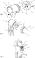
- FIG Figure 3 shows an overall perspective view of a quick-release clamping device 1 according to the invention before the clamping device 3 is inserted into the axle unit 2.
- the coupling unit 16 of the clamping device 3 is thus shown in FIG Figure 3 recognizable.
- the axle unit 2 comprises the axle 5, which is designed here as a plug-in axle and extends along the axial direction 4.
- a clamping device 6 is provided on the first end 7 of the axle 5, while a fastening device 9 is arranged on the second end 10 of the axle 5.
- the fastening device 9 is designed as an external thread 26 on the axis 5.
- the axle unit 2 is introduced through the dropouts and the hub of an impeller and by means of the Clamping device 3, the axle unit 2 is fastened to the frame 103 in such a way that the hub 108 is clamped between the dropouts of the frame 103 or the fork 104.
- the clamping device 3 which comprises a clamping component 13 and an operating lever 12 attached to it, is used for operation.
- the coupling unit 16 of the clamping device 3 After the coupling unit 16 of the clamping device 3 has been inserted into the connection unit 17 (cf. Figure 5 ) of the axle unit 2, the coupling unit 16 is rotatably coupled to the axle unit 2, so that in the in Figure 3 engagement position 14 shown, a rotary movement of the operating lever 12 leads to a coupled rotary movement of the axle unit 2 and the axle 5 and thus also of the external thread 26 of the axle unit 2.
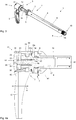
- Figure 4a shows a schematic cross section through the clamping device 3 and part of the axle unit 2 in the engagement position 14.
- connection unit 17 with a connection contour 19 (cf. Figure 5 ).
- the clamping device 3 is essentially constituted by the clamping component 13, an intermediate device 50 (cf. Figure 4a ) and the operating lever 12 is formed.
- the operating lever 12 has a clamping sleeve 31, which is here integrally and in one piece, from which the handle of the operating lever 12 extends radially outward.
- the approximately mushroom-shaped push button 22 is part of the actuating unit 51 and is firmly connected to the intermediate device 50.
- the push button 22 has a radially protruding collar 23 which forms a counter bearing 24 for the pretensioning device 21.
- the pretensioning device 21 is designed here as a spiral spring which is attached to a snap ring or O-ring at one end or the like is supported in an annular groove in a central bore of the clamping component 13. The other end is supported on the counter bearing 24.
- the intermediate device 50 is in the in Figure 4a engagement position 14 shown preloaded.
- the intermediate device 50 is non-rotatably connected to the clamping component 13. Furthermore, the intermediate device 50 is connected to the operating lever 12 in a rotationally fixed manner.
- the external toothing 39 of the clamping component 13 is in engagement with the internal toothing 54 of the intermediate device 50.
- the external toothing 53 of the intermediate device 50 is non-rotatably engaged with the internal toothing 40 of the clamping sleeve 31.
- the operating lever 12 is coupled to the clamping component 13 in a rotationally fixed manner.
- grooves 31a and 13c are provided in the clamping sleeve 31 and the clamping component 13, in which a snap ring 13c or an O-ring or the like is arranged.
- the assembly can be facilitated by a phase on the clamping sleeve 31.
- the contact washer 34 which rests on the axially outer side of the clamping device 6, is used for the contact and better guidance of the clamping device 3 on the axle unit 2.
- an O-ring 33 can be provided in the interior of the connection unit 17 of the clamping device 6.
- Figure 4b shows the clamping device 3 in a schematically sectioned representation in the second position 15 or the rotary position 15.
- the operating lever 12 can remain stationary here.
- the intermediate device with the push button 22 and the sleeve-like central part (transmission section 52) and the coupling contours 53 and 54 is moved axially inward, so that the pretensioning device 21 is axially compressed.
- the internal teeth 40 on the clamping sleeve 31 and the external teeth 53 on the intermediate device 50 are disengaged, so that a free rotational movement of the operating lever 12 in both directions of rotation is possible.
- the external toothing 39 on the clamping component 13 and the internal toothing 54 on the intermediate device 50 are also out of engagement.
- the user can press the push button 22 and turn the operating lever 12. This means that the user presses the push button 22 against the force of the pretensioning device 21 with his thumb, for example, in order to rotate the operating lever 12 in the rotary position 15. After turning into the desired position, the user can release the push button 22 so that the actuating unit 50 or the push button 22 automatically returns to the engagement position 14 due to the prestressing force of the prestressing device 21.
- Figure 5 shows another perspective illustration of part of the quick release device 1, wherein the connection unit 17 with the inner connection contour 19 on the axle unit 2 can be seen.
- the coupling unit 16 on the other hand, has an outer coupling contour 18 which is correspondingly adapted to the connection contour 19 of the connection unit 17.
- the coupling unit 16 and the connection unit 17 are designed as an external hexagon or internal hexagon.
- the push button 22 also forms here the actuation unit 51 of the intermediate device 50 inside.
- Figure 6 shows another embodiment of a quick release device 1 according to the invention, which in turn comprises an axle unit 2 and a clamping device 3.
- the coupling contour 18 of the coupling unit 16 is designed here as an external square, while a corresponding connection contour 19 of the connection unit 17 is provided in the axle unit 2 in order to accommodate the square of the coupling unit 16 with an accurate fit.
- a plurality of latching depressions 35 are provided on the axle unit 2, which are part of a latching device 20. Such locking depressions can be present in all exemplary embodiments.
- Figure 7 shows another perspective view of the quick release device 1 according to FIG Figure 6 , whereby the locking projection 36 of the locking device 20 on the coupling unit 16 can be seen here.
- the latching projection 36 is preloaded into the position shown by a spring and is used to latch with the latching recess 35 on the connection unit 17.
- An O-ring 38 is provided at the transition between the contact washer 34 and the coupling unit 16.
- a knurled washer 32 is provided on the clamping device 6.
- FIG Figure 8 shows part of a schematic cross section through the quick release device 1 according to FIG Figure 6 when assembled.
- the locking projection 36 is formed by a ball which is preloaded into the position shown by a locking spring 37.
- the ball and thus the locking projection 36 engages in one of the four locking recesses 35 provided here.
- the holding force can be adjusted by means of a corresponding spring force.
- the function of the Quick release device 1 is as in the previous embodiments.
- Figure 9 shows another highly schematic exemplary embodiment of a further quick release device 1 according to the invention.
- the clamping device 3 with the actuating unit 51 is shown on the left, while the axle unit 2 is shown schematically on the right.
- the actuation unit 51 of the intermediate device 50 is used for the optional coupling and decoupling of the operating lever 12 from the coupling contour 28, as described above.
- connection unit 17 forms a “male” connection contour 29 which can engage in a “female” coupling contour 28 of the coupling unit 16.
- connection contour 29 is designed here as a square, but can also be designed as a hexagon or have some other toothing that interacts with a corresponding toothing or the like of the coupling unit 16.
- a torque limiter 25 is provided here, which prevents a predetermined torque from being exceeded during assembly. This ensures that the intended torque is always applied during assembly with the operating lever 12 and is not exceeded.
- a torque limiter 25 can be present in all exemplary embodiments.
- FIG 11 shows a further exemplary embodiment of a quick release device according to the invention in a schematic perspective illustration, with the male connection contour 29 of the connection unit 17 protruding outward from the axle unit 2.
- a coupling unit 16 with a female coupling contour 28 is provided in the clamping device 3, into which the Connection contour 29 of connection unit 17 engages, for example, to mount or dismantle an impeller.
- a substantial part of the intermediate device is installed inside, which can be actuated via the control button as an actuating unit from the other side, which is not visible here, in order to decouple the control lever 12 from the clamping component 13.
- Figure 12 shows a schematic perspective illustration from the other side, so that the connection unit 17 with the connection contour 29, which is here male, can be clearly seen.
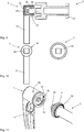
- Figure 13 shows a schematic cross-section through the quick release device 1, which functions with respect to the coupling of the operating lever 12 to the clamping component 1 here basically in exactly the same way as in all other exemplary embodiments.
- the connection contour 29 of the connection unit 17 protrudes into the clamping device 3 and is positively connected to the coupling contour 28 of the coupling unit 16.
- the pretensioning device 21 is supported differently than in the previous exemplary embodiments.
- the clamping component here has no continuous cavity 13a or a bore.
- the left end of the spiral spring 21 is supported, which preloads the intermediate device 50 into the engagement position 14.
- the intermediate device 50 or the push button 51 is secured axially to the left by a holder 31b on the clamping sleeve 31.
- the holder 31b can be part of a circumferential annular wall. Or the holder 31b is formed by individual lugs 31b.
- the holder 31b can be fastened to the clamping sleeve 31 by clamping, gluing or by screws or other fastening methods.
- the clamping sleeve 31 is axially secured here by a screw 13d (or several thereof).
- the screw 13d is screwed in from the outside.
- the end becomes axial in a circumferential groove 13c fixed so that the clamping sleeve is releasably attached.
- coupling contours 39, 40, 53, 54 are provided, which can optionally be coupled to one another or can be decoupled from one another.
- Figure 14 shows a further schematic cross-section through a quick release device 1, which functions with respect to the coupling of the operating lever 12 to the clamping component 1 here basically again in the same way as in all other exemplary embodiments.
- the coupling unit 16 of the clamping component 13 protrudes axially outward (male shape).
- a tool head or a tool 58 is integrated here at the axial end.
- the tool 58 has a smaller diameter than the coupling unit 16.
- a screwdriver tool is preferably integrated at the axial end.
- the tool 58 is designed as a Torx tool.
- a tool it is also possible for a tool to be able to be received in a non-rotatable manner in a cavity 13a of the clamping component.
- a bit of different shape can be included.
- Fig. 15 shows variants of an intermediate piece 50 which is suitable for use in all exemplary embodiments.
- a variant is shown in dashed lines in the upper half in which the radial outer contour (external toothing) 53a extends over a greater length and in particular over the essential length of the clamping sleeve 31.
- the coupling contour 40 inner contour
- the coupling contour 54 disengages from the coupling contour 39 in the rotational position.
- the invention provides a lightweight quick release device 1 that is very is easy to use.
- the fact that the operating lever 12 can be brought out of engagement with the clamping component 13 enables simple assembly and disassembly of running wheels.
- the length of the clamping component 13, which regularly consists of solid steel, can be significantly reduced. Even if the tensioning component 13 is to be formed partially or completely from a lighter metal or the like, the overall weight can be considerably reduced here overall. This also applies when a tool 58 is formed at the axial end of the clamping component 13.
- a clamping device 3 is arranged only on the rear wheel, while only one axle unit 2 remains on the front wheel.
Landscapes
- Engineering & Computer Science (AREA)
- Mechanical Engineering (AREA)
- Axle Suspensions And Sidecars For Cycles (AREA)
Claims (13)
- Dispositif de serrage rapide (1), en particulier pour deux-roues (100) à propulsion au moins partiellement humaine tels que des bicyclettes, avec une unité d'essieu (2) et un dispositif de serrage (3),l'unité d'essieu (2) ayant un essieu (5) se prolongeant dans la direction axiale (4), un dispositif de pinçage (6) à la première extrémité (7) de l'unité d'essieu (2) et un dispositif de fixation (9) à une deuxième extrémité (10) de l'unité d'essieu (2), le dispositif de serrage (3) étant adapté pour le montage et démontage de l'unité d'essieu (2) sur un deux-roues (100),le dispositif de serrage (3) comprenant un levier d'actionnement (12) et un composant de serrage (13), le composant de serrage (13) pouvant être couplé de manière immobile en rotation à l'unité d'essieu (2), et le composant de serrage (13) pouvant être découplé de l'unité d'essieu (2), le dispositif de serrage (3) comprenant un dispositif intermédiaire (50) avec une unité d'actionnement (51), et l'unité d'actionnement (51) assurant dans une première position (14) une connexion immobile en rotation du composant de serrage (13) et du levier d'actionnement (12) et permettant dans une seconde position (15) au levier de commande (12) de pivoter par rapport au composant de serrage (13), tandis que le composant de serrage (13) peut être couplé de manière immobile en rotation à l'unité d'essieu (2),caractérisé en ce quele composant de serrage (13) présente une unité de couplage (16) avec un contour de couplage non circulaire (18, 28) pour le couplage à une unité de raccordement (17) conformément adaptée avec un contour de raccordement non circulaire (19, 29) sur l'unité d'essieu (2),et en ce que sur le levier d'actionnement (12), le dispositif intermédiaire (50) et sur le composant de serrage (13) sont respectivement formés des contours de couplage non circulaires (39, 40, 53 , 54) adaptés l'un à l'autre, qui dans la position d'engagement (14) sont engagés l'un avec l'autre, en particulier au moins une partie des contours de couplage non circulaires (39, 40, 53, 54) étant formés sous la forme de dentures sur le levier d'actionnement (12) et le composant de serrage (13) et le dispositif intermédiaire (50) et un rapport d'une longueur de recouvrement (41) de l'unité de couplage réciproque (16) et de l'unité de raccordement (17) engagés l'un avec l'autre et d'un diamètre (42) de l'unité de couplage étant inférieur à 4:1.
- Dispositif de serrage rapide (1) selon la revendication 1, dans lequel un outil supplémentaire (58) est agencé au composant de serrage (13).
- Dispositif de serrage rapide (1) selon l'une des revendications précédentes, dans lequel l'unité de couplage (16) du composant de serrage (13) est inséré dans le contour de raccordement (19) pour le montage et le démontage ou dans lequel l'unité de couplage (16) du composant de serrage (13) est appliqué sur le contour de raccordement (29) de l'unité de raccordement (17) pour le montage et le démontage.
- Dispositif de serrage rapide (1) selon la revendication précédente, dans lequel l'unité de couplage (16) présente un polygone extérieur (18) et/ou un polygone intérieur (28).
- Dispositif de serrage rapide (1) selon l'une des revendications précédentes, dans lequel au moins un dispositif d'encliquetage (20) est prévu pour verrouiller le composant de serrage (13) à l'unité d'essieu (2) afin d'accueillir le composant de serrage (13) sur l'unité d'essieu (2) de manière imperdable.
- Dispositif de serrage rapide (1) selon l'une des revendications précédentes, dans lequel l'unité d'actionnement (51) peut être déplacée par un mouvement dans la direction axiale (4) par rapport au composant de serrage (13) afin d'influencer un couplage du levier d'actionnement (12) et du composant de serrage (13).
- Dispositif de serrage rapide (1) selon l'une des revendications précédentes, dans lequel l'unité d'actionnement (51) est précontrainte dans la position d'engagement (14) via un dispositif de précontrainte (21).
- Dispositif de serrage rapide (1) selon l'une des revendications précédentes, dans lequel le composant de serrage (13) présente à une extrémité l'unité de couplage (16) pour le couplage à l'unité d'essieu (2) et à l'autre extrémité un bouton-poussoir (22) munie d'une collerette (23).
- Dispositif de serrage rapide (1) selon l'une des revendications précédentes, dans lequel le levier d'actionnement (12) est couplé dans la position d'engagement (14) à l'unité d'essieu (2) via un limiteur de couple (25).
- Dispositif de serrage rapide (1) selon l'une des revendications précédentes, dans lequel l'unité d'essieu (2) est creuse au moins à la deuxième extrémité (10) et/ou dans lequel l'unité d'essieu (3) présente un filetage extérieur (26) en tant que dispositif de fixation (9) à la deuxième extrémité (7).
- Dispositif de serrage rapide (1) selon l'une des revendications précédentes, dans lequel le dispositif de fixation (9) comporte une fermeture à baïonnette (27).
- Deux-roues (100) avec un châssis (103) et une fourche (104) et un entraînement (112) à propulsion au moins partiellement humaine et deux roues (101, 102), à savoir une roue avant (101) et une roue arrière (102), chaque roue comportant un moyeu (108) et un dispositif de serrage rapide (1) selon au moins l'une des revendications 1 à 11.
- Deux-roues (100) selon la revendication 12, dans lequel exactement un dispositif de serrage (3) est prévu pour le montage et le démontage des roues (101, 102) et/ou dans lequel le dispositif de serrage (3) est fixée de manière amovible sur l'unité d'essieu (2) de la roue arrière (102).
Applications Claiming Priority (1)
| Application Number | Priority Date | Filing Date | Title |
|---|---|---|---|
| DE102016103080.5A DE102016103080A1 (de) | 2016-02-22 | 2016-02-22 | Schnellspannvorrichtung |
Publications (2)
| Publication Number | Publication Date |
|---|---|
| EP3246238A1 EP3246238A1 (fr) | 2017-11-22 |
| EP3246238B1 true EP3246238B1 (fr) | 2021-10-06 |
Family
ID=58185273
Family Applications (1)
| Application Number | Title | Priority Date | Filing Date |
|---|---|---|---|
| EP17157194.6A Active EP3246238B1 (fr) | 2016-02-22 | 2017-02-21 | Dispositif de serrage rapide |
Country Status (4)
| Country | Link |
|---|---|
| US (1) | US10293638B2 (fr) |
| EP (1) | EP3246238B1 (fr) |
| DE (1) | DE102016103080A1 (fr) |
| TW (1) | TWI720118B (fr) |
Families Citing this family (4)
| Publication number | Priority date | Publication date | Assignee | Title |
|---|---|---|---|---|
| US11458765B2 (en) | 2017-02-14 | 2022-10-04 | Dt Swiss Inc. | Quick release device |
| US20190168540A1 (en) * | 2017-12-04 | 2019-06-06 | Michael Louis Schlags | Wheel To Axle Securement System |
| TWI731318B (zh) * | 2019-03-21 | 2021-06-21 | 温宜玲 | 自行車輪的快拆裝置 |
| EP4574446A1 (fr) * | 2023-12-22 | 2025-06-25 | Glory Wheel Enterprise Co., Ltd. | Bicyclette à axe traversant hautement adaptative |
Family Cites Families (14)
| Publication number | Priority date | Publication date | Assignee | Title |
|---|---|---|---|---|
| DE1400057U (fr) | ||||
| US4508614A (en) * | 1982-11-08 | 1985-04-02 | Mobil Oil Corporation | Visbreaker performance for production of heating oil |
| DE3347433A1 (de) * | 1983-12-29 | 1985-07-11 | Heinrich Kipp Werk, 7247 Sulz | Handhebel |
| US6089675A (en) * | 1997-08-19 | 2000-07-18 | Schlanger; Raphael | Quick release bicycle hub assembly |
| DE29714945U1 (de) * | 1997-08-20 | 1997-10-09 | Formula Engineering Inc., Shen-Kang Hsiang, Taichung | Baueinheit aus einer Achse und einer Achsenmontagevorrichtung |
| DE102005062702A1 (de) | 2005-12-24 | 2007-07-12 | Dt Swiss Ag | Schnellspanner, insbesondere für Fahrräder |
| US7494145B2 (en) | 2006-10-27 | 2009-02-24 | Answer Products, Inc. | Axle with non-round tapered ends affixed into fork leg dropouts with openings that match the axle ends for a bicycle fork |
| ITMC20070108A1 (it) * | 2007-05-25 | 2008-11-26 | Marzocchi Spa | Perno ruota per cicli e motocicli provvisto di un dispositivo limitatore di coppia di serraggio. |
| IT1400057B1 (it) | 2010-05-07 | 2013-05-17 | Tech Suspension S R L | Dispositivo di blocco/sblocco rapido per ruote di motociclette e biciclette. |
| TWI439388B (zh) * | 2012-06-08 | 2014-06-01 | A Pro Tech Co Ltd | Bicycle quick release anti - loosening device |
| DE102013013819A1 (de) * | 2013-08-22 | 2015-02-26 | Dt Swiss Ag | Schnellspanner |
| TW201540595A (zh) * | 2014-04-18 | 2015-11-01 | Ken Chang Ind Co Ltd | 按鈕式可調整角度快拆 |
| DE102014112084A1 (de) * | 2014-08-22 | 2016-02-25 | Dt Swiss Ag | Schnellspannvorrichtung |
| DE202015005524U1 (de) * | 2015-08-05 | 2015-10-02 | tune U. Fahl e.K. | Schnellverschluss für Fahrräder mit Justierfunktion |
-
2016
- 2016-02-22 DE DE102016103080.5A patent/DE102016103080A1/de not_active Withdrawn
-
2017
- 2017-01-25 TW TW106102904A patent/TWI720118B/zh active
- 2017-02-14 US US15/432,744 patent/US10293638B2/en active Active
- 2017-02-21 EP EP17157194.6A patent/EP3246238B1/fr active Active
Non-Patent Citations (1)
| Title |
|---|
| None * |
Also Published As
| Publication number | Publication date |
|---|---|
| US20170239984A1 (en) | 2017-08-24 |
| US10293638B2 (en) | 2019-05-21 |
| DE102016103080A1 (de) | 2017-08-24 |
| TW201730039A (zh) | 2017-09-01 |
| TWI720118B (zh) | 2021-03-01 |
| EP3246238A1 (fr) | 2017-11-22 |
Similar Documents
| Publication | Publication Date | Title |
|---|---|---|
| EP2987713B1 (fr) | Dispositif de serrage rapide | |
| EP1990265B2 (fr) | Système d'axe d'enfichage destiné à la fixation de roue | |
| DE4205579A1 (de) | Zentralsicherungseinrichtung fuer kraftfahrzeugraeder | |
| EP3023325B1 (fr) | Composant de vélo comprenant une butée et butée | |
| DE102015121218B3 (de) | Schnellspann-Steckachse für Zweiräder | |
| DE102008013938A1 (de) | Fahrradkomponente | |
| DE102013013819A1 (de) | Schnellspanner | |
| EP3246238A1 (fr) | Dispositif de serrage rapide | |
| DE102007019288B4 (de) | Fahrradnabe | |
| EP3133311A1 (fr) | Moyeu de roue arriere et axe de velo | |
| DE102010024473A1 (de) | Achssystem für ein Zweirad | |
| EP2125499A1 (fr) | Axe de blocage rapide | |
| EP1912854B1 (fr) | Dispositif de reglage de l'angle d'inclinaison d'une selle | |
| DE202015106650U1 (de) | Schnellspann-Steckachse für Zweiräder | |
| EP2591991A2 (fr) | Système de fixation pour roue de bicyclette | |
| EP2030885A1 (fr) | Poignée de vélo | |
| EP2243693B1 (fr) | Poignée de vélo | |
| EP2881314B1 (fr) | Poignée de vélo | |
| DE202011109857U1 (de) | Befestigungssystem eines Laufrads für ein Fahrrad | |
| DE102018107703A1 (de) | Schnellspannvorrichtung | |
| DE202016100934U1 (de) | Schnellspannvorrichtung | |
| DE102017007362A1 (de) | Elektromotor, insbesondere für Fahrzeug | |
| DE19614494C1 (de) | Diebstahlsicherung für Fahrräder durch Verhinderung des Antriebs | |
| DE102019130146B4 (de) | Verfahren zur Befestigung eines Bremshebels an einem Lenker eines Fahrzeugs mit einer Montageanordnung und Montageanordnung zur Durchführung des Verfahrens | |
| DE102023121288A1 (de) | Steckachsenanordnung zum Befestigen eines Rades an einem Fahrrad |
Legal Events
| Date | Code | Title | Description |
|---|---|---|---|
| PUAI | Public reference made under article 153(3) epc to a published international application that has entered the european phase |
Free format text: ORIGINAL CODE: 0009012 |
|
| STAA | Information on the status of an ep patent application or granted ep patent |
Free format text: STATUS: THE APPLICATION HAS BEEN PUBLISHED |
|
| AK | Designated contracting states |
Kind code of ref document: A1 Designated state(s): AL AT BE BG CH CY CZ DE DK EE ES FI FR GB GR HR HU IE IS IT LI LT LU LV MC MK MT NL NO PL PT RO RS SE SI SK SM TR |
|
| AX | Request for extension of the european patent |
Extension state: BA ME |
|
| STAA | Information on the status of an ep patent application or granted ep patent |
Free format text: STATUS: REQUEST FOR EXAMINATION WAS MADE |
|
| 17P | Request for examination filed |
Effective date: 20180518 |
|
| RBV | Designated contracting states (corrected) |
Designated state(s): AL AT BE BG CH CY CZ DE DK EE ES FI FR GB GR HR HU IE IS IT LI LT LU LV MC MK MT NL NO PL PT RO RS SE SI SK SM TR |
|
| STAA | Information on the status of an ep patent application or granted ep patent |
Free format text: STATUS: EXAMINATION IS IN PROGRESS |
|
| 17Q | First examination report despatched |
Effective date: 20200219 |
|
| GRAP | Despatch of communication of intention to grant a patent |
Free format text: ORIGINAL CODE: EPIDOSNIGR1 |
|
| STAA | Information on the status of an ep patent application or granted ep patent |
Free format text: STATUS: GRANT OF PATENT IS INTENDED |
|
| GRAJ | Information related to disapproval of communication of intention to grant by the applicant or resumption of examination proceedings by the epo deleted |
Free format text: ORIGINAL CODE: EPIDOSDIGR1 |
|
| STAA | Information on the status of an ep patent application or granted ep patent |
Free format text: STATUS: EXAMINATION IS IN PROGRESS |
|
| INTG | Intention to grant announced |
Effective date: 20210222 |
|
| INTC | Intention to grant announced (deleted) | ||
| GRAP | Despatch of communication of intention to grant a patent |
Free format text: ORIGINAL CODE: EPIDOSNIGR1 |
|
| STAA | Information on the status of an ep patent application or granted ep patent |
Free format text: STATUS: GRANT OF PATENT IS INTENDED |
|
| INTG | Intention to grant announced |
Effective date: 20210428 |
|
| GRAS | Grant fee paid |
Free format text: ORIGINAL CODE: EPIDOSNIGR3 |
|
| GRAA | (expected) grant |
Free format text: ORIGINAL CODE: 0009210 |
|
| STAA | Information on the status of an ep patent application or granted ep patent |
Free format text: STATUS: THE PATENT HAS BEEN GRANTED |
|
| AK | Designated contracting states |
Kind code of ref document: B1 Designated state(s): AL AT BE BG CH CY CZ DE DK EE ES FI FR GB GR HR HU IE IS IT LI LT LU LV MC MK MT NL NO PL PT RO RS SE SI SK SM TR |
|
| REG | Reference to a national code |
Ref country code: GB Ref legal event code: FG4D Free format text: NOT ENGLISH |
|
| REG | Reference to a national code |
Ref country code: CH Ref legal event code: EP Ref country code: AT Ref legal event code: REF Ref document number: 1436004 Country of ref document: AT Kind code of ref document: T Effective date: 20211015 |
|
| REG | Reference to a national code |
Ref country code: DE Ref legal event code: R096 Ref document number: 502017011638 Country of ref document: DE |
|
| REG | Reference to a national code |
Ref country code: IE Ref legal event code: FG4D Free format text: LANGUAGE OF EP DOCUMENT: GERMAN |
|
| REG | Reference to a national code |
Ref country code: LT Ref legal event code: MG9D |
|
| REG | Reference to a national code |
Ref country code: NL Ref legal event code: MP Effective date: 20211006 |
|
| PG25 | Lapsed in a contracting state [announced via postgrant information from national office to epo] |
Ref country code: RS Free format text: LAPSE BECAUSE OF FAILURE TO SUBMIT A TRANSLATION OF THE DESCRIPTION OR TO PAY THE FEE WITHIN THE PRESCRIBED TIME-LIMIT Effective date: 20211006 Ref country code: LT Free format text: LAPSE BECAUSE OF FAILURE TO SUBMIT A TRANSLATION OF THE DESCRIPTION OR TO PAY THE FEE WITHIN THE PRESCRIBED TIME-LIMIT Effective date: 20211006 Ref country code: FI Free format text: LAPSE BECAUSE OF FAILURE TO SUBMIT A TRANSLATION OF THE DESCRIPTION OR TO PAY THE FEE WITHIN THE PRESCRIBED TIME-LIMIT Effective date: 20211006 Ref country code: BG Free format text: LAPSE BECAUSE OF FAILURE TO SUBMIT A TRANSLATION OF THE DESCRIPTION OR TO PAY THE FEE WITHIN THE PRESCRIBED TIME-LIMIT Effective date: 20220106 |
|
| PG25 | Lapsed in a contracting state [announced via postgrant information from national office to epo] |
Ref country code: IS Free format text: LAPSE BECAUSE OF FAILURE TO SUBMIT A TRANSLATION OF THE DESCRIPTION OR TO PAY THE FEE WITHIN THE PRESCRIBED TIME-LIMIT Effective date: 20220206 Ref country code: SE Free format text: LAPSE BECAUSE OF FAILURE TO SUBMIT A TRANSLATION OF THE DESCRIPTION OR TO PAY THE FEE WITHIN THE PRESCRIBED TIME-LIMIT Effective date: 20211006 Ref country code: PT Free format text: LAPSE BECAUSE OF FAILURE TO SUBMIT A TRANSLATION OF THE DESCRIPTION OR TO PAY THE FEE WITHIN THE PRESCRIBED TIME-LIMIT Effective date: 20220207 Ref country code: PL Free format text: LAPSE BECAUSE OF FAILURE TO SUBMIT A TRANSLATION OF THE DESCRIPTION OR TO PAY THE FEE WITHIN THE PRESCRIBED TIME-LIMIT Effective date: 20211006 Ref country code: NO Free format text: LAPSE BECAUSE OF FAILURE TO SUBMIT A TRANSLATION OF THE DESCRIPTION OR TO PAY THE FEE WITHIN THE PRESCRIBED TIME-LIMIT Effective date: 20220106 Ref country code: NL Free format text: LAPSE BECAUSE OF FAILURE TO SUBMIT A TRANSLATION OF THE DESCRIPTION OR TO PAY THE FEE WITHIN THE PRESCRIBED TIME-LIMIT Effective date: 20211006 Ref country code: LV Free format text: LAPSE BECAUSE OF FAILURE TO SUBMIT A TRANSLATION OF THE DESCRIPTION OR TO PAY THE FEE WITHIN THE PRESCRIBED TIME-LIMIT Effective date: 20211006 Ref country code: HR Free format text: LAPSE BECAUSE OF FAILURE TO SUBMIT A TRANSLATION OF THE DESCRIPTION OR TO PAY THE FEE WITHIN THE PRESCRIBED TIME-LIMIT Effective date: 20211006 Ref country code: GR Free format text: LAPSE BECAUSE OF FAILURE TO SUBMIT A TRANSLATION OF THE DESCRIPTION OR TO PAY THE FEE WITHIN THE PRESCRIBED TIME-LIMIT Effective date: 20220107 Ref country code: ES Free format text: LAPSE BECAUSE OF FAILURE TO SUBMIT A TRANSLATION OF THE DESCRIPTION OR TO PAY THE FEE WITHIN THE PRESCRIBED TIME-LIMIT Effective date: 20211006 |
|
| REG | Reference to a national code |
Ref country code: DE Ref legal event code: R097 Ref document number: 502017011638 Country of ref document: DE |
|
| PG25 | Lapsed in a contracting state [announced via postgrant information from national office to epo] |
Ref country code: SM Free format text: LAPSE BECAUSE OF FAILURE TO SUBMIT A TRANSLATION OF THE DESCRIPTION OR TO PAY THE FEE WITHIN THE PRESCRIBED TIME-LIMIT Effective date: 20211006 Ref country code: SK Free format text: LAPSE BECAUSE OF FAILURE TO SUBMIT A TRANSLATION OF THE DESCRIPTION OR TO PAY THE FEE WITHIN THE PRESCRIBED TIME-LIMIT Effective date: 20211006 Ref country code: RO Free format text: LAPSE BECAUSE OF FAILURE TO SUBMIT A TRANSLATION OF THE DESCRIPTION OR TO PAY THE FEE WITHIN THE PRESCRIBED TIME-LIMIT Effective date: 20211006 Ref country code: EE Free format text: LAPSE BECAUSE OF FAILURE TO SUBMIT A TRANSLATION OF THE DESCRIPTION OR TO PAY THE FEE WITHIN THE PRESCRIBED TIME-LIMIT Effective date: 20211006 Ref country code: DK Free format text: LAPSE BECAUSE OF FAILURE TO SUBMIT A TRANSLATION OF THE DESCRIPTION OR TO PAY THE FEE WITHIN THE PRESCRIBED TIME-LIMIT Effective date: 20211006 Ref country code: CZ Free format text: LAPSE BECAUSE OF FAILURE TO SUBMIT A TRANSLATION OF THE DESCRIPTION OR TO PAY THE FEE WITHIN THE PRESCRIBED TIME-LIMIT Effective date: 20211006 |
|
| PLBE | No opposition filed within time limit |
Free format text: ORIGINAL CODE: 0009261 |
|
| STAA | Information on the status of an ep patent application or granted ep patent |
Free format text: STATUS: NO OPPOSITION FILED WITHIN TIME LIMIT |
|
| 26N | No opposition filed |
Effective date: 20220707 |
|
| PG25 | Lapsed in a contracting state [announced via postgrant information from national office to epo] |
Ref country code: MC Free format text: LAPSE BECAUSE OF FAILURE TO SUBMIT A TRANSLATION OF THE DESCRIPTION OR TO PAY THE FEE WITHIN THE PRESCRIBED TIME-LIMIT Effective date: 20211006 |
|
| REG | Reference to a national code |
Ref country code: CH Ref legal event code: PL |
|
| REG | Reference to a national code |
Ref country code: BE Ref legal event code: MM Effective date: 20220228 |
|
| PG25 | Lapsed in a contracting state [announced via postgrant information from national office to epo] |
Ref country code: LU Free format text: LAPSE BECAUSE OF NON-PAYMENT OF DUE FEES Effective date: 20220221 Ref country code: AL Free format text: LAPSE BECAUSE OF FAILURE TO SUBMIT A TRANSLATION OF THE DESCRIPTION OR TO PAY THE FEE WITHIN THE PRESCRIBED TIME-LIMIT Effective date: 20211006 |
|
| PG25 | Lapsed in a contracting state [announced via postgrant information from national office to epo] |
Ref country code: SI Free format text: LAPSE BECAUSE OF FAILURE TO SUBMIT A TRANSLATION OF THE DESCRIPTION OR TO PAY THE FEE WITHIN THE PRESCRIBED TIME-LIMIT Effective date: 20211006 |
|
| PG25 | Lapsed in a contracting state [announced via postgrant information from national office to epo] |
Ref country code: LI Free format text: LAPSE BECAUSE OF NON-PAYMENT OF DUE FEES Effective date: 20220228 Ref country code: IE Free format text: LAPSE BECAUSE OF NON-PAYMENT OF DUE FEES Effective date: 20220221 Ref country code: CH Free format text: LAPSE BECAUSE OF NON-PAYMENT OF DUE FEES Effective date: 20220228 |
|
| PG25 | Lapsed in a contracting state [announced via postgrant information from national office to epo] |
Ref country code: BE Free format text: LAPSE BECAUSE OF NON-PAYMENT OF DUE FEES Effective date: 20220228 |
|
| REG | Reference to a national code |
Ref country code: AT Ref legal event code: MM01 Ref document number: 1436004 Country of ref document: AT Kind code of ref document: T Effective date: 20220221 |
|
| PG25 | Lapsed in a contracting state [announced via postgrant information from national office to epo] |
Ref country code: AT Free format text: LAPSE BECAUSE OF NON-PAYMENT OF DUE FEES Effective date: 20220221 |
|
| PG25 | Lapsed in a contracting state [announced via postgrant information from national office to epo] |
Ref country code: IT Free format text: LAPSE BECAUSE OF FAILURE TO SUBMIT A TRANSLATION OF THE DESCRIPTION OR TO PAY THE FEE WITHIN THE PRESCRIBED TIME-LIMIT Effective date: 20211006 |
|
| P01 | Opt-out of the competence of the unified patent court (upc) registered |
Effective date: 20230517 |
|
| PG25 | Lapsed in a contracting state [announced via postgrant information from national office to epo] |
Ref country code: HU Free format text: LAPSE BECAUSE OF FAILURE TO SUBMIT A TRANSLATION OF THE DESCRIPTION OR TO PAY THE FEE WITHIN THE PRESCRIBED TIME-LIMIT; INVALID AB INITIO Effective date: 20170221 |
|
| PG25 | Lapsed in a contracting state [announced via postgrant information from national office to epo] |
Ref country code: MK Free format text: LAPSE BECAUSE OF FAILURE TO SUBMIT A TRANSLATION OF THE DESCRIPTION OR TO PAY THE FEE WITHIN THE PRESCRIBED TIME-LIMIT Effective date: 20211006 Ref country code: CY Free format text: LAPSE BECAUSE OF FAILURE TO SUBMIT A TRANSLATION OF THE DESCRIPTION OR TO PAY THE FEE WITHIN THE PRESCRIBED TIME-LIMIT Effective date: 20211006 |
|
| PG25 | Lapsed in a contracting state [announced via postgrant information from national office to epo] |
Ref country code: MT Free format text: LAPSE BECAUSE OF FAILURE TO SUBMIT A TRANSLATION OF THE DESCRIPTION OR TO PAY THE FEE WITHIN THE PRESCRIBED TIME-LIMIT Effective date: 20211006 |
|
| PG25 | Lapsed in a contracting state [announced via postgrant information from national office to epo] |
Ref country code: TR Free format text: LAPSE BECAUSE OF FAILURE TO SUBMIT A TRANSLATION OF THE DESCRIPTION OR TO PAY THE FEE WITHIN THE PRESCRIBED TIME-LIMIT Effective date: 20211006 |
|
| PGFP | Annual fee paid to national office [announced via postgrant information from national office to epo] |
Ref country code: GB Payment date: 20260218 Year of fee payment: 10 |
|
| PGFP | Annual fee paid to national office [announced via postgrant information from national office to epo] |
Ref country code: DE Payment date: 20260224 Year of fee payment: 10 |
|
| PGFP | Annual fee paid to national office [announced via postgrant information from national office to epo] |
Ref country code: FR Payment date: 20260218 Year of fee payment: 10 |