EP3246258B1 - Dosenfüll-/-falzvorrichtung und dosenfüll-/falzverfahren - Google Patents
Dosenfüll-/-falzvorrichtung und dosenfüll-/falzverfahren Download PDFInfo
- Publication number
- EP3246258B1 EP3246258B1 EP15878011.4A EP15878011A EP3246258B1 EP 3246258 B1 EP3246258 B1 EP 3246258B1 EP 15878011 A EP15878011 A EP 15878011A EP 3246258 B1 EP3246258 B1 EP 3246258B1
- Authority
- EP
- European Patent Office
- Prior art keywords
- turret
- filling
- forwarding
- conveyance path
- seaming
- Prior art date
- Legal status (The legal status is an assumption and is not a legal conclusion. Google has not performed a legal analysis and makes no representation as to the accuracy of the status listed.)
- Active
Links
Images


Classifications
-
- B—PERFORMING OPERATIONS; TRANSPORTING
- B21—MECHANICAL METAL-WORKING WITHOUT ESSENTIALLY REMOVING MATERIAL; PUNCHING METAL
- B21D—WORKING OR PROCESSING OF SHEET METAL OR METAL TUBES, RODS OR PROFILES WITHOUT ESSENTIALLY REMOVING MATERIAL; PUNCHING METAL
- B21D51/00—Making hollow objects
- B21D51/16—Making hollow objects characterised by the use of the objects
- B21D51/26—Making hollow objects characterised by the use of the objects cans or tins; Closing same in a permanent manner
- B21D51/30—Folding the circumferential seam
- B21D51/32—Folding the circumferential seam by rolling
-
- B—PERFORMING OPERATIONS; TRANSPORTING
- B67—OPENING, CLOSING OR CLEANING BOTTLES, JARS OR SIMILAR CONTAINERS; LIQUID HANDLING
- B67B—APPLYING CLOSURE MEMBERS TO BOTTLES JARS, OR SIMILAR CONTAINERS; OPENING CLOSED CONTAINERS
- B67B3/00—Closing bottles, jars or similar containers by applying caps
- B67B3/02—Closing bottles, jars or similar containers by applying caps by applying flanged caps, e.g. crown caps, and securing by deformation of flanges
- B67B3/06—Feeding caps to capping heads
-
- B—PERFORMING OPERATIONS; TRANSPORTING
- B21—MECHANICAL METAL-WORKING WITHOUT ESSENTIALLY REMOVING MATERIAL; PUNCHING METAL
- B21D—WORKING OR PROCESSING OF SHEET METAL OR METAL TUBES, RODS OR PROFILES WITHOUT ESSENTIALLY REMOVING MATERIAL; PUNCHING METAL
- B21D51/00—Making hollow objects
- B21D51/16—Making hollow objects characterised by the use of the objects
- B21D51/26—Making hollow objects characterised by the use of the objects cans or tins; Closing same in a permanent manner
- B21D51/2653—Methods or machines for closing cans by applying caps or bottoms
- B21D51/2661—Sealing or closing means therefor
-
- B—PERFORMING OPERATIONS; TRANSPORTING
- B21—MECHANICAL METAL-WORKING WITHOUT ESSENTIALLY REMOVING MATERIAL; PUNCHING METAL
- B21D—WORKING OR PROCESSING OF SHEET METAL OR METAL TUBES, RODS OR PROFILES WITHOUT ESSENTIALLY REMOVING MATERIAL; PUNCHING METAL
- B21D51/00—Making hollow objects
- B21D51/16—Making hollow objects characterised by the use of the objects
- B21D51/26—Making hollow objects characterised by the use of the objects cans or tins; Closing same in a permanent manner
- B21D51/30—Folding the circumferential seam
-
- B—PERFORMING OPERATIONS; TRANSPORTING
- B65—CONVEYING; PACKING; STORING; HANDLING THIN OR FILAMENTARY MATERIAL
- B65B—MACHINES, APPARATUS OR DEVICES FOR, OR METHODS OF, PACKAGING ARTICLES OR MATERIALS; UNPACKING
- B65B7/00—Closing containers or receptacles after filling
- B65B7/16—Closing semi-rigid or rigid containers or receptacles not deformed by, or not taking-up shape of, contents, e.g. boxes or cartons
- B65B7/28—Closing semi-rigid or rigid containers or receptacles not deformed by, or not taking-up shape of, contents, e.g. boxes or cartons by applying separate preformed closures, e.g. lids, covers
-
- B—PERFORMING OPERATIONS; TRANSPORTING
- B67—OPENING, CLOSING OR CLEANING BOTTLES, JARS OR SIMILAR CONTAINERS; LIQUID HANDLING
- B67B—APPLYING CLOSURE MEMBERS TO BOTTLES JARS, OR SIMILAR CONTAINERS; OPENING CLOSED CONTAINERS
- B67B3/00—Closing bottles, jars or similar containers by applying caps
- B67B3/02—Closing bottles, jars or similar containers by applying caps by applying flanged caps, e.g. crown caps, and securing by deformation of flanges
-
- B—PERFORMING OPERATIONS; TRANSPORTING
- B67—OPENING, CLOSING OR CLEANING BOTTLES, JARS OR SIMILAR CONTAINERS; LIQUID HANDLING
- B67C—CLEANING, FILLING WITH LIQUIDS OR SEMILIQUIDS, OR EMPTYING, OF BOTTLES, JARS, CANS, CASKS, BARRELS, OR SIMILAR CONTAINERS, NOT OTHERWISE PROVIDED FOR; FUNNELS
- B67C3/00—Bottling liquids or semiliquids; Filling jars or cans with liquids or semiliquids using bottling or like apparatus; Filling casks or barrels with liquids or semiliquids
- B67C3/02—Bottling liquids or semiliquids; Filling jars or cans with liquids or semiliquids using bottling or like apparatus
- B67C3/22—Details
- B67C3/222—Head-space air removing devices, e.g. by inducing foam
-
- B—PERFORMING OPERATIONS; TRANSPORTING
- B67—OPENING, CLOSING OR CLEANING BOTTLES, JARS OR SIMILAR CONTAINERS; LIQUID HANDLING
- B67C—CLEANING, FILLING WITH LIQUIDS OR SEMILIQUIDS, OR EMPTYING, OF BOTTLES, JARS, CANS, CASKS, BARRELS, OR SIMILAR CONTAINERS, NOT OTHERWISE PROVIDED FOR; FUNNELS
- B67C7/00—Concurrent cleaning, filling, and closing of bottles; Processes or devices for at least two of these operations
- B67C7/0006—Conveying; Synchronising
- B67C7/004—Conveying; Synchronising the containers travelling along a circular path
- B67C7/0046—Infeed and outfeed devices
-
- B—PERFORMING OPERATIONS; TRANSPORTING
- B65—CONVEYING; PACKING; STORING; HANDLING THIN OR FILAMENTARY MATERIAL
- B65B—MACHINES, APPARATUS OR DEVICES FOR, OR METHODS OF, PACKAGING ARTICLES OR MATERIALS; UNPACKING
- B65B57/00—Automatic control, checking, warning, or safety devices
- B65B57/10—Automatic control, checking, warning, or safety devices responsive to absence, presence, abnormal feed, or misplacement of articles or materials to be packaged
- B65B57/14—Automatic control, checking, warning, or safety devices responsive to absence, presence, abnormal feed, or misplacement of articles or materials to be packaged and operating to control, or stop, the feed of articles or material to be packaged
-
- B—PERFORMING OPERATIONS; TRANSPORTING
- B67—OPENING, CLOSING OR CLEANING BOTTLES, JARS OR SIMILAR CONTAINERS; LIQUID HANDLING
- B67C—CLEANING, FILLING WITH LIQUIDS OR SEMILIQUIDS, OR EMPTYING, OF BOTTLES, JARS, CANS, CASKS, BARRELS, OR SIMILAR CONTAINERS, NOT OTHERWISE PROVIDED FOR; FUNNELS
- B67C3/00—Bottling liquids or semiliquids; Filling jars or cans with liquids or semiliquids using bottling or like apparatus; Filling casks or barrels with liquids or semiliquids
- B67C3/02—Bottling liquids or semiliquids; Filling jars or cans with liquids or semiliquids using bottling or like apparatus
- B67C3/06—Bottling liquids or semiliquids; Filling jars or cans with liquids or semiliquids using bottling or like apparatus using counterpressure, i.e. filling while the container is under pressure
- B67C3/12—Pressure-control devices
-
- B—PERFORMING OPERATIONS; TRANSPORTING
- B67—OPENING, CLOSING OR CLEANING BOTTLES, JARS OR SIMILAR CONTAINERS; LIQUID HANDLING
- B67C—CLEANING, FILLING WITH LIQUIDS OR SEMILIQUIDS, OR EMPTYING, OF BOTTLES, JARS, CANS, CASKS, BARRELS, OR SIMILAR CONTAINERS, NOT OTHERWISE PROVIDED FOR; FUNNELS
- B67C3/00—Bottling liquids or semiliquids; Filling jars or cans with liquids or semiliquids using bottling or like apparatus; Filling casks or barrels with liquids or semiliquids
- B67C3/02—Bottling liquids or semiliquids; Filling jars or cans with liquids or semiliquids using bottling or like apparatus
- B67C3/22—Details
Definitions
- the present invention relates to a can filling/seaming device and a can filling/seaming method for filling a can with a content and seaming a lid to a can.
- a conventional filling/seaming device includes a rotary filling machine (filler) that successively fills a can of a metal material with a liquid content such as a beverage, and a seaming machine (seamer) that successively seals a lid (metal lid) to a flange part of the filled can by seaming.
- a filler generally used has a plurality of holding parts (pockets) provided at the circular outer circumference of a rotating filling turret to receive and hold a can, and a filling nozzle that moves in synchronization with each of the holding parts is provided above the holding part.
- Successively supplied cans are sequentially held by the filling turret of the filler and then filled with a prescribed amount of liquid content from the respective filling nozzles while being conveyed by the rotation of the filling turret.
- the filled cans once removed from the filling turret are transported to a feeding conveyer or a hook-up conveyer and conveyed to the seamer.
- the seamer sequentially supplies lids to the flange parts of the filled cans supplied from the feed conveyer or the hook-up conveyer, and the flange parts of the cans and the curled parts of the lids are joined by double-seaming by roll processing, so that the lids are attached and sealed to the cans (see JP 2006-36266 ).
- a device according to the preamble of claim 1 is disclosed in DE8916109U .
- the filling/seaming devices are designed in various forms for different uses, and particularly when a can filled with a liquid content is sealed with a lid by seaming, it is inevitable to take precautions to prevent the content from spilling from the can in a conveyance path between the filling of the content and the seaming with the lid.
- the conventional filling/seaming device described above has a relatively long linear intermediate conveyance path by a feeding conveyer or a hook-up conveyer between the filler and the seamer, so that the can filled with the content is not subject to high acceleration or centrifugal force during the conveyance in the path.
- an object of the invention is to allow the filler and the seamer to be integrated in a compact arrangement in a can filling/seaming device and a can filling/seaming method for filling a can with a liquid content and seaming a lid
- another object is to simplify installation works and reduce the number of days for the device to be set up for operation by eliminating the necessity of positional adjustment and timing adjustment during transport from the filler to the intermediate conveyance path and from the intermediate conveyance path to the seamer
- yet another object is to reduce works related to timing deviation inspection and timing adjustment in daily use
- a still further object is to reduce the manufacturing cost by eliminating the necessity of using a special driving device for timing adjustment.
- a can filling/seaming device and a can filling/seaming method according to the present invention are defined in claims 1 and 7 and include among others the following features.
- the can filling/seaming device includes a filler that fills a can with a liquid content while conveying the can by rotation of a filling turret, a seamer that attaches a lid to the can filled with the content by double-seaming, and a forwarding turret provided between a carrying-out position of the filling turret and a carrying-in position to the seamer to circularly convey the can filled with the content, wherein a lid supply part is provided on the forwarding turret.
- the can filling/seaming method includes filling a can with a liquid content while conveying the can along a circular conveyance path of a filling turret, transporting the can filled with the content from the filling turret to a forwarding turret and supplying the can with a lid while conveying the can along a circular conveyance path of the forwarding turret, and transporting the can supplied with the lid from the forwarding turret to a seamer and attaching the lid to the can by double-seaming while conveying the can along a circular conveyance path of the seamer.
- a filler that fills the can with the content and the seamer that seams the lid to the can may be integrated through a forwarding turret in a compact arrangement, so that the installation area can be reduced.
- acceleration curvature
- the installation area can be reduced while keeping high filling accuracy.
- Positional adjustment and timing adjustment during transport from the filler to the forwarding turret or from the forwarding turret to the seamer can be abolished, so that installation works can be simplified and the number of days for the device to be set up for operation can be reduced. In daily use, works related to timing deviation inspection or timing adjustment can be reduced, and use of a special driving device for timing adjustment is not necessary, which can lower the manufacturing cost.
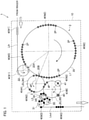
- a can filling/seaming device 1 includes a filler 2, a seamer 3, and a forwarding turret 4.
- the can W to be described herein is a can having a flange part at the open end, and W1 designates an empty can, W2 designates a can that is being filled with a liquid content such as a beverage or is already filled with the content, and W3 designates a can sealed with a lid by double-seaming in the drawings.
- the filler 2 includes a filling turret 20 and fills a can W with a liquid content while conveying the can W by rotation of the filling turret 20.
- the filling turret 20 includes a plurality of pockets 2P that hold cans W at its circular outer circumference, and the pockets 2P are arranged at a set conveyance pitch P1 in a circular conveyance path L1 with a pitch diameter D1.
- a filling nozzle (not shown) that moves in synchronization with each of the pockets 2P is provided above the pocket 2P, and the filling nozzle fills the can W with a liquid content between the carrying-in position 20A and the carrying-out position 20B of the filling turret 20.
- the can W (empty can W1) is supplied to the filler 2 via an appropriate carrying-in path L in from a rinser that cleans the cans W.
- a carrying-in turret 22 that receives and delivers the cans W to the pockets 2P of the filling turret 20 or a rinser turret (not shown) that cleans the cans W may be additionally provided to the carrying-in turret 22.
- the seamer 3 attaches a lid to the flange part of the can filled with the content, by double-seaming by roll processing, and while a can W, on which a lid is placed, is conveyed in a circular conveyance path L2 from a carrying-in position 3A to a carrying-out position 3B, the flange part of the can and the curled part of the lid are subjected to double-seaming by roll processing, so that the can W is sealed.
- a pitch diameter D2 and a conveyance pitch P2 are set as appropriate in the circular conveyance path L2 of the seamer 3.
- the can W carried out from the seamer 3 is carried outside the device via an appropriate carrying-out path L out .
- a discharging turret 30 that receives and forwards the can W discharged from the seamer 3 while rotating in the direction of the shown arrow may be provided, or an inspector turret 31 that carries out various kinds of inspection including inspection about a filling amount with respect to the can W discharged from the discharging turret 30 may be provided.
- two forwarding turrets 4A and 4B are provided between the carrying-out position 20B of the filling turret 20 and the carrying-in position 3A of the seamer 3 and circularly convey the can W filled with the content, and pockets 4P are provided at respective conveyance pitches P3A and P3B in the circular conveyance paths L3A and L3B with respective pitch diameters D3A and D3B.
- the pitch diameters D3A and D3B of the forwarding turrets 4A and 4B are equal and the conveyance pitches P3A and P3B are equal in this example, the arrangement is not limited to the above.
- the forwarding turret 4B between the forwarding turrets 4A and 4B is provided with a lid supply part 40 in the circular conveyance path L3B.
- the lid supply part 40 may be a lid supply device directly provided in the circular conveyance path L3B or may be provided on an additional lid supply turret provided in the carrying-in position 3A to the seamer 3 in the circular conveyance path L3B.
- the forwarding turret 4B may include, if necessary, a liquid nitrogen filling part 41 provided in the circular conveyance path L3B to fill the can W with liquid nitrogen so that the can is kept under positive pressure and reduced in the thickness.
- the first forwarding turret 4A may be dedicated to conveyance of the cans W, so that the filling nozzle of the filler 2 needs only to avoid the can W in the carrying-out position 20B of the filling turret 20.
- the filling nozzle may be set in a low level, the rotation angle of the filler 2 allocated for filling may be increased, and the filler 2 may be reduced in size.
- the cans W filled with the content and transported from the carrying-out position 20B of the filling turret 20 to the forwarding turrets 4A and 4B are filled with nitrogen if necessary while moving in the respective circular conveyance paths L3A and L3B, and then the cans W have lids placed at the flange parts thereof at the lid supply part 40 and are transported to the seamer 3.
- the cans W filled with the content and transported to the forwarding turrets 4A and 4B are subject to acceleration (centrifugal force) by moving in the circular conveyance paths L3A and L3B.
- the conveyance pitches P1, P2, P3A, and P3B of the filling turret 20 of the filler 2, the seamer 3, and the forwarding turrets 4A and 4B are all equal.
- the conveyance pitches P1, P2, P3A, and P3B may have difference in an allowable range, and the device can still be designed.
- the conveyance pitch (pocket pitch) P1 of the filling turret 20 and the conveyance pitches (pocket pitches) P3A and P3B of the forwarding turrets 4A and 4B need only be in the range that enables pocket pass in the transport from the filling turret 20 to the forwarding turrets 4A and 4B.
- the production capacity is 600 CPM (Cans Per Minute i.e. production per minute)
- the conveyance pitches P1, P2, P3A, and P3B are all 31 ⁇ (97.4 mm)
- the conveyance speed is constant at 0.97 m/s.
- the centrifugal acceleration (3.82 m/s 2 ) of the forwarding turrets 4A and 4B is set in the allowable range where the acceleration a max is 4.16 m/s 2 .
- the filler 2 and the seamer 3 are coupled by the forwarding turrets 4A and 4B, so that the filler 2 and the seamer 3 may be integrated in a compact arrangement through the forwarding turrets 4A and 4B.
- the filler 2, the seamer 3, and the forwarding turrets 4A and 4B can be provided on a common frame 10.
- the cans W are all turret-conveyed at accurately determined conveyance pitches from the filler 2 to the seamer 3, so that the process is not influenced by change with time that would be caused by the expansion of a chain used in linear conveyance, and positional adjustment and timing adjustment that would otherwise be necessary in transport from the filler 2 to the forwarding turrets 4A and 4B and from the forwarding turrets 4A and 4B to the seamer 3 can be abolished by making the conveyance pitches P1, P2, P3A, and P3B close to one another.
- a lid supply turret may serve both to deoxidize the headspace of the can W with a replacement gas and supply the lid, and in the case, the filling nozzle of the filler 2 must avoid the lid supply turret positioned above the can W in the carrying-out position 20B of the filling turret 20.
- the filling nozzle must be set in a high position, must finish filling in an early stage and then must be raised, and the rotation angle of the filler 2 allocated for filling is reduced, so that the filler 2 is increased in size.
- a separate lid supply turret (lid supply part 40) that carries out deoxidization and supply of the lid may be provided in the carrying-in position 3A for the can W from the forwarding turret 4 to the seamer 3, so that the rotation angle of the filler 2 allocated for filling can be increased.
- the filling/seaming device is formed in a box structure surrounded by covers entirely or partly until a lid is sealed by seaming after filling, and the inside is kept under positive pressure with an inert gas for the purpose of deoxidization or with filtered air for the purpose of preventing contamination and improving the hygiene state.
- Fig. 2 is a view of a filling/seaming device 1A according to another embodiment of the invention.
- the same elements as those according to the above-described embodiment are designated by the same reference characters, and their description will not be repeated.
- the embodiment is related to an example having both a carrying-out path L out 1 for producing a normal seam can sealed with a lid by double-seaming and a discharge path L out 2 for forming a small-diameter mouth part at a can and producing a bottle can sealed with a cap (metal cap) and the like, the filler 2 and the forwarding turret 4A out of the two forwarding turrets 4A and 4B are both used, and a branching forwarding turret 5 that branches a conveyance path to a capper 6 for capping a cap to the mouth part of the bottle can is provided in the conveyance path L3A of the forwarding turret 4A.
- the bottle can W filled with a content by the filler 2 is conveyed from the forwarding turret 4A via the branching forwarding turret 5 to the capper 6 and capped with a cap while being conveyed at the capper 6.
- the bottle can W discharged from the capper 6 is discharged outside the device through a discharge path L out 2 via an inspector turret 60 that carries out various kinds of inspection including inspection about a filling amount.
- the filler 2 the seamer 3, the forwarding turrets 4A and 4B, the branching forwarding turret 5, the capper 6 and the like may be integrated in a compact arrangement, and these elements can be provided on a common frame 10.
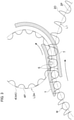
- Fig. 3 is a view of an exemplary configuration of a transport portion between turrets in a can filling/seaming device according to the invention.
- a liquid-filled can conveyed by one turret has its liquid surface inclined by centrifugal force received during the conveyance, and then when the can is transported to the other turret, the liquid surface is inclined to the opposite side, and the liquid surface vibrates and is prone to a problem such as spilling or foaming.
- This may be disadvantageous in transport of the can after the can is filled, particularly at the filling/seaming device that fills the can with a liquid content and seals the lid to the can by double-seaming mentioned above.
- Acceleration change applied on the can is infinite, so that the can that is conveyed becomes unstable in position and may interfere with, e.g., a transport guide or the pockets of the turret, which may cause a defect such as a damage and a dent on the can.
- an acceleration relaxation curve S that continuously changes the acceleration applied on the can W that is conveyed is provided in the transport portion from the filling turret 20 to the forwarding turret 4A.
- the circular conveyance path L1 of the filling turret 20 and the circular conveyance path L3A of the forwarding turret 4A are provided with a prescribed gap therebetween, in which a transport guide 7 that transports the can W along a prescribed track is provided.
- the guide surface shape of the transport guide 7 is formed along a transition curve (the acceleration relaxation curve S) that continuously changes from the pitch circle curvature of the circular conveyance path L1 of the filling turret 20 to the pitch circle curvature of the circular conveyance path L3A of the forwarding turret 4A.
- the acceleration relaxation curve S is provided in the transport portion for the can W between the filling turret 20 and the forwarding turret 4A, so that the liquid surface of the can W filled with a liquid content can be suppressed from vibrating during the transport. In this way, the problem such as spilling and foaming of the content during the transport of the can between the filling turret 20 and the forwarding turret 4A can be solved.
- transport along an acceleration relaxation curve for the same purpose can be carried out in the transport portions between the forwarding turret 4A and the forwarding turret 4B and between the forwarding turret 4B and the seamer 3, and the same advantageous effect can be obtained.
- the can filling/seaming device 1 (1A) when the can filling/seaming device 1 (1A) according to the present invention fills a can with a liquid content and seals the can with a lid by double-seaming, the filler 2 and the seamer 3 are coupled by the forwarding turret 4 (4A, 4B), so that use of a linear intermediate conveyance path or a special driving device for timing adjustment may be abolished, which can reduce the installation cost and the installation area.
- the acceleration (curvature) is limited at the forwarding turret 4 so that the content filled in the can does not spill from the can, transport in, for example, the transport portion from the filling turret 20 to the forwarding turret 4 (4A, 4B) is carried out along the acceleration relaxation curve, and therefore the installation area can be reduced while keeping high filling accuracy.
- the forwarding turret 4 (4A, 4B) is provided with the lid supply part 40 or may be provided with the liquid nitrogen filling part 41, and therefore the device may be provided in a compact form.
Landscapes
- Engineering & Computer Science (AREA)
- Mechanical Engineering (AREA)
- Filling Of Jars Or Cans And Processes For Cleaning And Sealing Jars (AREA)
- Closing Of Containers (AREA)
Claims (10)
- Dosenabfüll-/-verschlussvorrichtung (1, 1A), umfassend:ein Füllgerät (2), das konfiguriert ist, um eine Dose (W) mit einem flüssigen Inhalt zu befüllen, während er die Dose (W) durch Drehung eines Füllrevolvers (20) befördert, der eine Vielzahl von Taschen (2P) beinhaltet;ein Verschließgerät (3), das konfiguriert ist, um durch Doppelfalzen einen Deckel an der mit dem Inhalt gefüllten Dose (W) anzubringen; undeinen Vorschubrevolver (4, 4A, 4B), der eine Vielzahl von Taschen (4P) aufweist,wobei der Vorschubrevolver zwischen einer Ausbringposition (20B) des Füllrevolvers (20) und einer Einbringposition (3A) zu dem Verschließgerät (3) bereitgestellt ist, um die mit dem Inhalt befüllte Dose (W) kreisförmig zu fördern,wobei das Deckelzuführungsteil (40) auf dem Vorschubrevolver (4, 4A, 4B) bereitgestellt ist,dadurch gekennzeichnet, dasseine Transportführung (7) in dem Transportabschnitt von dem Füllrevolver (20) zu dem Vorschubrevolver (4A) bereitgestellt ist,die Führungsflächenform der Transportführung (7) entlang einer Übergangskurve gebildet ist, die kontinuierlich von der Kreiskrümmung der kreisförmigen Förderbahn (L1) des Füllrevolvers (20) zu der Kreiskrümmung der kreisförmigen Förderbahn (L3A) des Vorschubrevolvers (4A) übergeht,die kreisförmige Förderbahn (L1) des Füllrevolvers (20) und die kreisförmige Förderbahn (L3A) des Vorschubrevolvers (4A) mit einem Spalt dazwischen versehen sind, und eine Dosentransportspur in dem Spalt durch die Transportführung (7) gebildet wird.
- Dosenabfüll-/-verschlussvorrichtung (1, 1A) gemäß Anspruch 1, wobei die Förderbahn (L3A) und die Transportspur derart sind, dass eine Beschleunigung, die auf die von dem Vorschubrevolver (4, 4A, 4B) geförderte Dose (W) einwirkt, geringer eingestellt ist als die durch den Ausdruck Amax = (2h/D) × G definierte Beschleunigung amax,
wobei h die lichte Höhe der Dose (W), D der Körperdurchmesser der Dose (W) und G Erdbeschleunigung ist. - Dosenabfüll-/-verschlussvorrichtung (1, 1A) gemäß Anspruch 1 oder 2, wobei eine Fördersteigung für den Füllrevolver (20) und den Vorschubrevolver (4, 4A, 4B) innerhalb eines solchen Bereichs eingestellt ist, dass ein Taschendurchlauf während des Transports von dem Füllrevolver (20) zu dem Vorschubrevolver (4, 4A, 4B) ermöglicht wird.
- Dosenabfüll-/-verschlussvorrichtung (1, 1A) gemäß Anspruch 1 oder 2, wobei eine Transportführung (7) an einem Transportabschnitt von dem Vorschubrevolver (4B) zu dem Verschließgerät (3) bereitgestellt ist, und
die Führungsflächenform der Transportführung (7) entlang einer Übergangskurve gebildet ist, die kontinuierlich von der Kreiskrümmung der kreisförmigen Förderbahn (L3B) des Vorschubrevolvers (4B) zu der Kreiskrümmung der kreisförmigen Förderbahn (L2) des Verschließgeräts (3) übergeht, - Dosenabfüll-/-verschlussvorrichtung (1, 1A) gemäß einem der Ansprüche 1 bis 4, wobei in einem Förderweg (L3, L3A, L3B) des Vorschubrevolvers (4, 4A, 4B) ein abzweigender Vorschubrevolver (5) bereitgestellt ist, wobei der abzweigende Vorschubrevolver (5) die Förderbahn (L3, L3A, L3B) zu einem Verschließgerät (6) abzweigt, der eine Kappe auf einem Mundteil einer Flaschendose aufdeckelt.
- Dosenabfüll-/-verschlussvorrichtung (1, 1A) gemäß einem der Ansprüche 1 bis 5, wobei das Füllgerät (2), das Verschließgerät (3) und der Vorschubrevolver (4, 4A, 4B) an einem gemeinsamen Rahmen (10) platziert sind.
- Dosenabfüll-/-verschlussverfahren, umfassend:Befüllen einer Dose (W) mit einem flüssigen Inhalt, während die Dose (W) entlang einer kreisförmigen Förderbahn (L1) eines Füllrevolvers (20) gefördert wird;Transportieren der mit dem Inhalt gefüllten Dose (W) von dem Füllrevolver (20) zu einem Vorschubrevolver (4, 4A, 4B) und Versehen der Dose (W) mit einem Deckel, während die Dose (W) entlang einer kreisförmigen Förderbahn (L3, L3A,L3B) des Vorschubrevolvers (4, 4A, 4B) befördert wird;wobei die kreisförmige Förderbahn (L1) des Füllrevolvers (20) und die kreisförmige Förderbahn (L3A) des Vorschubrevolvers (4A) mit einem Spalt dazwischen versehen sind, und durch eine Transportspur (7) eine Dosentransportspur in dem Spalt gebildet ist; undTransportieren der mit dem Deckel versehenen Dose (W) von dem Vorschubrevolver (4, 4A, 4B) zu einem Verschließgerät (3) und Befestigen des Deckels an der Dose (W) durch Doppelfalzung, während die Dose (W) entlang einer kreisförmigen Transportbahn (L2) des Verschließgeräts (3) transportiert wird,wobei das Transportieren von dem Füllrevolver (20) zu einem Vorschubrevolver (4A) entlang einer Übergangskurve gebildet wird, die kontinuierlich von der Kreiskrümmung der kreisförmigen Förderbahn (L1) des Füllrevolvers (20) zu der Kreiskrümmung der kreisförmigen Förderbahn (L3A) des Vorschubrevolvers (4A) übergeht.
- Dosenabfüll-/-verschlussverfahren gemäß Anspruch 7, wobei die auf die von dem Transportrevolver (4, 4A, 4B) beförderte Dose (W) ausgeübte Beschleunigung geringer ist als die durch amax = (2h/D) × G definierte Beschleunigung, wobei h eine lichte Höhe der mit dem Inhalt gefüllten Dose (W) ist, D ein Durchmesser der Dose (W) ist und G Erdbeschleunigung ist.
- Dosenabfüll-/-verschlussverfahren gemäß Anspruch 7 oder 8, wobei der Transport von dem Transportrevolver (4B) zu dem Verschließgerät (3) entlang einer Übergangskurve erfolgt, die kontinuierlich von der Kreiskrümmung der kreisförmigen Transportbahn (L3B) des Transportrevolvers (4B) zu der Kreiskrümmung der kreisförmigen Transportbahn (L2) des Verschließgeräts (3) übergeht.
- Dosenabfüll-/-verschlussverfahren gemäß einem der Ansprüche 7 bis 9, wobei der Förderweg (L3, L3A, L3B) des Vorschubrevolvers (4, 4A, 4B) zu einem Verschließgerät (6) abzweigt, der eine Kappe auf einem Mundteil einer Flaschendose aufdeckelt.
Applications Claiming Priority (2)
| Application Number | Priority Date | Filing Date | Title |
|---|---|---|---|
| JP2015006268A JP6716858B2 (ja) | 2015-01-15 | 2015-01-15 | 缶体の充填巻締装置及び充填巻締方法 |
| PCT/JP2015/085207 WO2016114060A1 (ja) | 2015-01-15 | 2015-12-16 | 缶体の充填巻締装置及び充填巻締方法 |
Publications (3)
| Publication Number | Publication Date |
|---|---|
| EP3246258A1 EP3246258A1 (de) | 2017-11-22 |
| EP3246258A4 EP3246258A4 (de) | 2018-10-17 |
| EP3246258B1 true EP3246258B1 (de) | 2022-03-09 |
Family
ID=56405615
Family Applications (1)
| Application Number | Title | Priority Date | Filing Date |
|---|---|---|---|
| EP15878011.4A Active EP3246258B1 (de) | 2015-01-15 | 2015-12-16 | Dosenfüll-/-falzvorrichtung und dosenfüll-/falzverfahren |
Country Status (5)
| Country | Link |
|---|---|
| US (1) | US10987719B2 (de) |
| EP (1) | EP3246258B1 (de) |
| JP (1) | JP6716858B2 (de) |
| CN (1) | CN107207104B (de) |
| WO (1) | WO2016114060A1 (de) |
Families Citing this family (13)
| Publication number | Priority date | Publication date | Assignee | Title |
|---|---|---|---|---|
| US10591421B1 (en) * | 2014-02-25 | 2020-03-17 | Khs Gmbh | Beverage bottle handling device for handling beverage bottles and similar containers in a beverage bottling or container filling plant |
| JP6424511B2 (ja) * | 2014-08-08 | 2018-11-21 | 東洋製罐株式会社 | 物品の搬送方法及びその装置 |
| JP6693822B2 (ja) * | 2016-06-30 | 2020-05-13 | 株式会社吉野工業所 | 液体ブロー成形による容器製造方法 |
| JP6735651B2 (ja) * | 2016-10-20 | 2020-08-05 | ユニバーサル製缶株式会社 | ボトル缶の製造方法 |
| IT201700090958A1 (it) | 2017-08-07 | 2019-02-07 | Pe Labellers Spa | Macchina etichettatrice di contenitori. |
| DE102018208956A1 (de) * | 2018-06-06 | 2019-12-12 | Bausch + Ströbel Maschinenfabrik Ilshofen GmbH + Co. KG | Weichenvorrichtung |
| DE102018217860A1 (de) * | 2018-10-18 | 2020-04-23 | Krones Ag | Verfahren zum Handhaben von Dosen oder dergleichen Behältern in einer Füllmaschine und Füllmaschine |
| DE102019103892A1 (de) * | 2019-02-15 | 2020-08-20 | Khs Gmbh | Behälterbehandlungsvorrichtung |
| DE102019117377A1 (de) * | 2019-06-27 | 2020-12-31 | Khs Gmbh | Vorrichtung und Verfahren zum Transportieren von Behältern |
| WO2021181762A1 (ja) * | 2020-03-13 | 2021-09-16 | 東洋製罐グループエンジニアリング株式会社 | 容器部材供給装置 |
| ES2944183A1 (es) | 2021-12-17 | 2023-06-19 | Velategui Ignacio Escagedo | Equipo de soldadura por arco electrico |
| DE102021127638A1 (de) | 2021-10-25 | 2023-04-27 | Khs Gmbh | Getränkedosenfüllanlage und Verfahren zur Bildung gefüllter Getränkedosen |
| CN116281063B (zh) * | 2023-05-18 | 2023-08-04 | 四川省丹丹郫县豆瓣集团股份有限公司 | 一种豆瓣酱生产线自动排序装置 |
Family Cites Families (30)
| Publication number | Priority date | Publication date | Assignee | Title |
|---|---|---|---|---|
| DE1432416A1 (de) | 1964-06-05 | 1968-11-28 | Seitz Werke Gmbh | Verfahren zum Auflegen der Verschlussdeckel auf die gefuellten Dosen in Fuellmaschinen und zur Durchfuehrung des Verfahrens geeignete Fuellmaschine |
| US3415037A (en) * | 1965-11-12 | 1968-12-10 | Pneumatic Scale Corp | Closure feeding and transferring device |
| JPS4947328Y1 (de) * | 1967-08-15 | 1974-12-25 | ||
| JPS5747169B2 (de) | 1972-09-07 | 1982-10-07 | ||
| JPS5524933Y2 (de) * | 1975-08-30 | 1980-06-14 | ||
| JPS52125541U (de) * | 1976-03-19 | 1977-09-24 | ||
| JPS5936672B2 (ja) | 1976-04-13 | 1984-09-05 | 松下電器産業株式会社 | 接着方法 |
| DE2849741A1 (de) * | 1978-11-16 | 1980-05-29 | Seitz Werke Gmbh | Vorrichtung zum steuern eines sperrorgans fuer gefaess-verschliessmaschinen umlaufender bauart |
| DE3141364C2 (de) * | 1981-10-17 | 1984-12-20 | Krones Ag Hermann Kronseder Maschinenfabrik, 8402 Neutraubling | Vorrichtung zum Verteilen von aufrechtstehenden Gefäßen |
| DE3337425A1 (de) | 1983-10-14 | 1985-04-25 | Rheinmetall GmbH, 4000 Düsseldorf | Schliessvorrichtung an einer automatischen rohrwaffe, insbesondere maschinenkanone |
| JPS60101496U (ja) * | 1983-12-15 | 1985-07-10 | 三菱重工業株式会社 | 充填及び冠帽巻締装置 |
| IT1234085B (it) * | 1989-05-25 | 1992-04-29 | Azionaria Costruzioni Acma Spa | Apparecchiatura per posizionare in maniera corretta degli erogatori daapplicare a dei contenitori |
| DE3927911A1 (de) | 1989-08-24 | 1991-02-28 | Alfill Getraenketechnik | Verfahren und vorrichtung zum fuellen und verschliessen von dosen |
| DE8916109U1 (de) | 1989-08-24 | 1993-10-07 | Alfill Getränketechnik GmbH, 22309 Hamburg | Vorrichtung zum Füllen und Verschließen von Dosen |
| CH684404A5 (de) | 1991-11-27 | 1994-09-15 | Ferrum Ag | Vorrichtung zum Zuführen von Behältern zu einer Verschliesseinrichtung. |
| JPH09142649A (ja) * | 1995-11-17 | 1997-06-03 | Toyo Seikan Kaisha Ltd | フィラーにおける容器送り装置 |
| US6213309B1 (en) | 1999-04-30 | 2001-04-10 | B & H Manufacturing Company, Inc. | Turret feed control apparatus for sorting and distributing articles in a process system |
| JP3829578B2 (ja) * | 2000-04-11 | 2006-10-04 | 東洋製罐株式会社 | 充填装置 |
| JP3651367B2 (ja) * | 2000-07-11 | 2005-05-25 | 東洋製罐株式会社 | 缶詰製造方法及びその装置 |
| JP3991571B2 (ja) * | 2000-10-02 | 2007-10-17 | 東洋製罐株式会社 | 無菌充填陰圧缶詰製造方法及びその装置 |
| JP4761636B2 (ja) * | 2001-03-28 | 2011-08-31 | 日本クラウンコルク株式会社 | キャッピング装置 |
| US6915553B2 (en) * | 2003-02-19 | 2005-07-12 | Rexam Beverage Can Company | Seaming apparatus and method for cans |
| JP4420185B2 (ja) * | 2003-09-02 | 2010-02-24 | 東洋製罐株式会社 | 容器ヘッドスペースの処理方法および装置 |
| JP4252425B2 (ja) * | 2003-11-12 | 2009-04-08 | 東洋食品機械株式会社 | 容器の蓋締装置及びその搬送装置 |
| JP4758623B2 (ja) | 2004-07-27 | 2011-08-31 | 大和製罐株式会社 | 製造設備 |
| JP2006151483A (ja) * | 2004-11-30 | 2006-06-15 | Toyo Food Equipment Co Ltd | キャップ被冠装置 |
| JP4942346B2 (ja) * | 2006-01-17 | 2012-05-30 | 大和製罐株式会社 | キャッピング装置及びキャッピング方法 |
| US7568573B2 (en) * | 2007-09-21 | 2009-08-04 | Belvac Production Machinery, Inc. | High speed selective container sorter |
| DE102008052768A1 (de) * | 2008-10-22 | 2010-04-29 | Krones Ag | Vorrichtung zum Transportieren von Behältnissen |
| DE102012000758A1 (de) * | 2012-01-18 | 2013-07-18 | Khs Gmbh | Anlage sowie Verfahren zum Füllen von Behältern |
-
2015
- 2015-01-15 JP JP2015006268A patent/JP6716858B2/ja active Active
- 2015-12-16 US US15/538,378 patent/US10987719B2/en active Active
- 2015-12-16 CN CN201580073570.6A patent/CN107207104B/zh active Active
- 2015-12-16 EP EP15878011.4A patent/EP3246258B1/de active Active
- 2015-12-16 WO PCT/JP2015/085207 patent/WO2016114060A1/ja not_active Ceased
Non-Patent Citations (1)
| Title |
|---|
| None * |
Also Published As
| Publication number | Publication date |
|---|---|
| CN107207104A (zh) | 2017-09-26 |
| JP6716858B2 (ja) | 2020-07-01 |
| CN107207104B (zh) | 2020-02-28 |
| EP3246258A1 (de) | 2017-11-22 |
| US20170348757A1 (en) | 2017-12-07 |
| US10987719B2 (en) | 2021-04-27 |
| WO2016114060A1 (ja) | 2016-07-21 |
| EP3246258A4 (de) | 2018-10-17 |
| JP2016131979A (ja) | 2016-07-25 |
Similar Documents
| Publication | Publication Date | Title |
|---|---|---|
| EP3246258B1 (de) | Dosenfüll-/-falzvorrichtung und dosenfüll-/falzverfahren | |
| US20070000570A1 (en) | Beverage bottling plant for filling and closing beverage bottles with a packaging device for packaging beverage bottles | |
| JP6009001B2 (ja) | 容器の充填密封装置 | |
| US11332325B2 (en) | Apparatus for coating containers with bypass and method for operating such an apparatus | |
| JP6424511B2 (ja) | 物品の搬送方法及びその装置 | |
| US4721200A (en) | Can filling system to prevent damage to cans | |
| EP4159646B1 (de) | Behälterbehandlungssystem | |
| US12509340B2 (en) | Container feeding system for transporting container, as well as processing device and method for transporting container | |
| US20060130434A1 (en) | Beverage bottling plant for filling bottles with a liquid beverage material having a packing machine and a rotation machine for rotating packed boxes | |
| JP2019038586A (ja) | 搬送機構 | |
| CN108137246A (zh) | 中间存储装置和用于中间存储的方法 | |
| US4099621A (en) | Conveying and reject apparatus for upright standing bottles | |
| JP4252424B2 (ja) | 容器充填蓋締装置 | |
| GB2204307A (en) | Process and apparatus for transporting containers | |
| WO2024257459A1 (ja) | 有底筒状体加工装置 | |
| US4664159A (en) | Can filling system to prevent damage to cans | |
| CN112978656B (zh) | 用于导入或导出容器的装置和容器处理装置 | |
| JP2005145478A (ja) | 容器の蓋締装置及びその搬送装置 | |
| US11472635B2 (en) | Device, facility and method for ejecting products | |
| JP2023044460A (ja) | 容器処理システム | |
| JP2004161350A (ja) | キャッパにおけるガス置換装置 | |
| US3393490A (en) | Method and apparatus for assembling packages | |
| JP6636820B2 (ja) | 巻締装置 | |
| JP6521868B2 (ja) | 送り装置および連続的に送る方法 | |
| EP0006019A1 (de) | Maschine zum Füllen von Behältern mit Flüssigkeit |
Legal Events
| Date | Code | Title | Description |
|---|---|---|---|
| STAA | Information on the status of an ep patent application or granted ep patent |
Free format text: STATUS: THE INTERNATIONAL PUBLICATION HAS BEEN MADE |
|
| PUAI | Public reference made under article 153(3) epc to a published international application that has entered the european phase |
Free format text: ORIGINAL CODE: 0009012 |
|
| STAA | Information on the status of an ep patent application or granted ep patent |
Free format text: STATUS: REQUEST FOR EXAMINATION WAS MADE |
|
| 17P | Request for examination filed |
Effective date: 20170731 |
|
| AK | Designated contracting states |
Kind code of ref document: A1 Designated state(s): AL AT BE BG CH CY CZ DE DK EE ES FI FR GB GR HR HU IE IS IT LI LT LU LV MC MK MT NL NO PL PT RO RS SE SI SK SM TR |
|
| AX | Request for extension of the european patent |
Extension state: BA ME |
|
| DAV | Request for validation of the european patent (deleted) | ||
| DAX | Request for extension of the european patent (deleted) | ||
| A4 | Supplementary search report drawn up and despatched |
Effective date: 20180913 |
|
| RIC1 | Information provided on ipc code assigned before grant |
Ipc: B67B 3/02 20060101ALI20180907BHEP Ipc: B65B 7/28 20060101AFI20180907BHEP Ipc: B67B 3/06 20060101ALI20180907BHEP Ipc: B21D 51/30 20060101ALI20180907BHEP Ipc: B67C 7/00 20060101ALI20180907BHEP |
|
| STAA | Information on the status of an ep patent application or granted ep patent |
Free format text: STATUS: EXAMINATION IS IN PROGRESS |
|
| 17Q | First examination report despatched |
Effective date: 20200515 |
|
| GRAP | Despatch of communication of intention to grant a patent |
Free format text: ORIGINAL CODE: EPIDOSNIGR1 |
|
| STAA | Information on the status of an ep patent application or granted ep patent |
Free format text: STATUS: GRANT OF PATENT IS INTENDED |
|
| INTG | Intention to grant announced |
Effective date: 20211124 |
|
| GRAS | Grant fee paid |
Free format text: ORIGINAL CODE: EPIDOSNIGR3 |
|
| GRAA | (expected) grant |
Free format text: ORIGINAL CODE: 0009210 |
|
| STAA | Information on the status of an ep patent application or granted ep patent |
Free format text: STATUS: THE PATENT HAS BEEN GRANTED |
|
| AK | Designated contracting states |
Kind code of ref document: B1 Designated state(s): AL AT BE BG CH CY CZ DE DK EE ES FI FR GB GR HR HU IE IS IT LI LT LU LV MC MK MT NL NO PL PT RO RS SE SI SK SM TR |
|
| REG | Reference to a national code |
Ref country code: GB Ref legal event code: FG4D |
|
| REG | Reference to a national code |
Ref country code: CH Ref legal event code: EP Ref country code: AT Ref legal event code: REF Ref document number: 1473970 Country of ref document: AT Kind code of ref document: T Effective date: 20220315 |
|
| REG | Reference to a national code |
Ref country code: DE Ref legal event code: R096 Ref document number: 602015077490 Country of ref document: DE |
|
| REG | Reference to a national code |
Ref country code: IE Ref legal event code: FG4D |
|
| REG | Reference to a national code |
Ref country code: LT Ref legal event code: MG9D |
|
| REG | Reference to a national code |
Ref country code: NL Ref legal event code: MP Effective date: 20220309 |
|
| PG25 | Lapsed in a contracting state [announced via postgrant information from national office to epo] |
Ref country code: SE Free format text: LAPSE BECAUSE OF FAILURE TO SUBMIT A TRANSLATION OF THE DESCRIPTION OR TO PAY THE FEE WITHIN THE PRESCRIBED TIME-LIMIT Effective date: 20220309 Ref country code: RS Free format text: LAPSE BECAUSE OF FAILURE TO SUBMIT A TRANSLATION OF THE DESCRIPTION OR TO PAY THE FEE WITHIN THE PRESCRIBED TIME-LIMIT Effective date: 20220309 Ref country code: NO Free format text: LAPSE BECAUSE OF FAILURE TO SUBMIT A TRANSLATION OF THE DESCRIPTION OR TO PAY THE FEE WITHIN THE PRESCRIBED TIME-LIMIT Effective date: 20220609 Ref country code: LT Free format text: LAPSE BECAUSE OF FAILURE TO SUBMIT A TRANSLATION OF THE DESCRIPTION OR TO PAY THE FEE WITHIN THE PRESCRIBED TIME-LIMIT Effective date: 20220309 Ref country code: HR Free format text: LAPSE BECAUSE OF FAILURE TO SUBMIT A TRANSLATION OF THE DESCRIPTION OR TO PAY THE FEE WITHIN THE PRESCRIBED TIME-LIMIT Effective date: 20220309 Ref country code: BG Free format text: LAPSE BECAUSE OF FAILURE TO SUBMIT A TRANSLATION OF THE DESCRIPTION OR TO PAY THE FEE WITHIN THE PRESCRIBED TIME-LIMIT Effective date: 20220609 |
|
| REG | Reference to a national code |
Ref country code: AT Ref legal event code: MK05 Ref document number: 1473970 Country of ref document: AT Kind code of ref document: T Effective date: 20220309 |
|
| PG25 | Lapsed in a contracting state [announced via postgrant information from national office to epo] |
Ref country code: LV Free format text: LAPSE BECAUSE OF FAILURE TO SUBMIT A TRANSLATION OF THE DESCRIPTION OR TO PAY THE FEE WITHIN THE PRESCRIBED TIME-LIMIT Effective date: 20220309 Ref country code: GR Free format text: LAPSE BECAUSE OF FAILURE TO SUBMIT A TRANSLATION OF THE DESCRIPTION OR TO PAY THE FEE WITHIN THE PRESCRIBED TIME-LIMIT Effective date: 20220610 Ref country code: FI Free format text: LAPSE BECAUSE OF FAILURE TO SUBMIT A TRANSLATION OF THE DESCRIPTION OR TO PAY THE FEE WITHIN THE PRESCRIBED TIME-LIMIT Effective date: 20220309 |
|
| PG25 | Lapsed in a contracting state [announced via postgrant information from national office to epo] |
Ref country code: NL Free format text: LAPSE BECAUSE OF FAILURE TO SUBMIT A TRANSLATION OF THE DESCRIPTION OR TO PAY THE FEE WITHIN THE PRESCRIBED TIME-LIMIT Effective date: 20220309 |
|
| PG25 | Lapsed in a contracting state [announced via postgrant information from national office to epo] |
Ref country code: SM Free format text: LAPSE BECAUSE OF FAILURE TO SUBMIT A TRANSLATION OF THE DESCRIPTION OR TO PAY THE FEE WITHIN THE PRESCRIBED TIME-LIMIT Effective date: 20220309 Ref country code: SK Free format text: LAPSE BECAUSE OF FAILURE TO SUBMIT A TRANSLATION OF THE DESCRIPTION OR TO PAY THE FEE WITHIN THE PRESCRIBED TIME-LIMIT Effective date: 20220309 Ref country code: RO Free format text: LAPSE BECAUSE OF FAILURE TO SUBMIT A TRANSLATION OF THE DESCRIPTION OR TO PAY THE FEE WITHIN THE PRESCRIBED TIME-LIMIT Effective date: 20220309 Ref country code: PT Free format text: LAPSE BECAUSE OF FAILURE TO SUBMIT A TRANSLATION OF THE DESCRIPTION OR TO PAY THE FEE WITHIN THE PRESCRIBED TIME-LIMIT Effective date: 20220711 Ref country code: ES Free format text: LAPSE BECAUSE OF FAILURE TO SUBMIT A TRANSLATION OF THE DESCRIPTION OR TO PAY THE FEE WITHIN THE PRESCRIBED TIME-LIMIT Effective date: 20220309 Ref country code: EE Free format text: LAPSE BECAUSE OF FAILURE TO SUBMIT A TRANSLATION OF THE DESCRIPTION OR TO PAY THE FEE WITHIN THE PRESCRIBED TIME-LIMIT Effective date: 20220309 Ref country code: CZ Free format text: LAPSE BECAUSE OF FAILURE TO SUBMIT A TRANSLATION OF THE DESCRIPTION OR TO PAY THE FEE WITHIN THE PRESCRIBED TIME-LIMIT Effective date: 20220309 Ref country code: AT Free format text: LAPSE BECAUSE OF FAILURE TO SUBMIT A TRANSLATION OF THE DESCRIPTION OR TO PAY THE FEE WITHIN THE PRESCRIBED TIME-LIMIT Effective date: 20220309 |
|
| PG25 | Lapsed in a contracting state [announced via postgrant information from national office to epo] |
Ref country code: PL Free format text: LAPSE BECAUSE OF FAILURE TO SUBMIT A TRANSLATION OF THE DESCRIPTION OR TO PAY THE FEE WITHIN THE PRESCRIBED TIME-LIMIT Effective date: 20220309 Ref country code: IS Free format text: LAPSE BECAUSE OF FAILURE TO SUBMIT A TRANSLATION OF THE DESCRIPTION OR TO PAY THE FEE WITHIN THE PRESCRIBED TIME-LIMIT Effective date: 20220709 Ref country code: AL Free format text: LAPSE BECAUSE OF FAILURE TO SUBMIT A TRANSLATION OF THE DESCRIPTION OR TO PAY THE FEE WITHIN THE PRESCRIBED TIME-LIMIT Effective date: 20220309 |
|
| REG | Reference to a national code |
Ref country code: DE Ref legal event code: R097 Ref document number: 602015077490 Country of ref document: DE |
|
| PLBE | No opposition filed within time limit |
Free format text: ORIGINAL CODE: 0009261 |
|
| STAA | Information on the status of an ep patent application or granted ep patent |
Free format text: STATUS: NO OPPOSITION FILED WITHIN TIME LIMIT |
|
| PG25 | Lapsed in a contracting state [announced via postgrant information from national office to epo] |
Ref country code: DK Free format text: LAPSE BECAUSE OF FAILURE TO SUBMIT A TRANSLATION OF THE DESCRIPTION OR TO PAY THE FEE WITHIN THE PRESCRIBED TIME-LIMIT Effective date: 20220309 |
|
| 26N | No opposition filed |
Effective date: 20221212 |
|
| PG25 | Lapsed in a contracting state [announced via postgrant information from national office to epo] |
Ref country code: SI Free format text: LAPSE BECAUSE OF FAILURE TO SUBMIT A TRANSLATION OF THE DESCRIPTION OR TO PAY THE FEE WITHIN THE PRESCRIBED TIME-LIMIT Effective date: 20220309 |
|
| PG25 | Lapsed in a contracting state [announced via postgrant information from national office to epo] |
Ref country code: IT Free format text: LAPSE BECAUSE OF FAILURE TO SUBMIT A TRANSLATION OF THE DESCRIPTION OR TO PAY THE FEE WITHIN THE PRESCRIBED TIME-LIMIT Effective date: 20220309 |
|
| REG | Reference to a national code |
Ref country code: CH Ref legal event code: PL |
|
| GBPC | Gb: european patent ceased through non-payment of renewal fee |
Effective date: 20221216 |
|
| REG | Reference to a national code |
Ref country code: BE Ref legal event code: MM Effective date: 20221231 |
|
| PG25 | Lapsed in a contracting state [announced via postgrant information from national office to epo] |
Ref country code: LU Free format text: LAPSE BECAUSE OF NON-PAYMENT OF DUE FEES Effective date: 20221216 |
|
| PG25 | Lapsed in a contracting state [announced via postgrant information from national office to epo] |
Ref country code: LI Free format text: LAPSE BECAUSE OF NON-PAYMENT OF DUE FEES Effective date: 20221231 Ref country code: IE Free format text: LAPSE BECAUSE OF NON-PAYMENT OF DUE FEES Effective date: 20221216 Ref country code: GB Free format text: LAPSE BECAUSE OF NON-PAYMENT OF DUE FEES Effective date: 20221216 Ref country code: CH Free format text: LAPSE BECAUSE OF NON-PAYMENT OF DUE FEES Effective date: 20221231 |
|
| PG25 | Lapsed in a contracting state [announced via postgrant information from national office to epo] |
Ref country code: BE Free format text: LAPSE BECAUSE OF NON-PAYMENT OF DUE FEES Effective date: 20221231 |
|
| PG25 | Lapsed in a contracting state [announced via postgrant information from national office to epo] |
Ref country code: HU Free format text: LAPSE BECAUSE OF FAILURE TO SUBMIT A TRANSLATION OF THE DESCRIPTION OR TO PAY THE FEE WITHIN THE PRESCRIBED TIME-LIMIT; INVALID AB INITIO Effective date: 20151216 |
|
| PG25 | Lapsed in a contracting state [announced via postgrant information from national office to epo] |
Ref country code: CY Free format text: LAPSE BECAUSE OF FAILURE TO SUBMIT A TRANSLATION OF THE DESCRIPTION OR TO PAY THE FEE WITHIN THE PRESCRIBED TIME-LIMIT Effective date: 20220309 |
|
| PG25 | Lapsed in a contracting state [announced via postgrant information from national office to epo] |
Ref country code: MK Free format text: LAPSE BECAUSE OF FAILURE TO SUBMIT A TRANSLATION OF THE DESCRIPTION OR TO PAY THE FEE WITHIN THE PRESCRIBED TIME-LIMIT Effective date: 20220309 |
|
| PG25 | Lapsed in a contracting state [announced via postgrant information from national office to epo] |
Ref country code: MC Free format text: LAPSE BECAUSE OF FAILURE TO SUBMIT A TRANSLATION OF THE DESCRIPTION OR TO PAY THE FEE WITHIN THE PRESCRIBED TIME-LIMIT Effective date: 20220309 |
|
| PG25 | Lapsed in a contracting state [announced via postgrant information from national office to epo] |
Ref country code: MC Free format text: LAPSE BECAUSE OF FAILURE TO SUBMIT A TRANSLATION OF THE DESCRIPTION OR TO PAY THE FEE WITHIN THE PRESCRIBED TIME-LIMIT Effective date: 20220309 |
|
| PG25 | Lapsed in a contracting state [announced via postgrant information from national office to epo] |
Ref country code: MT Free format text: LAPSE BECAUSE OF FAILURE TO SUBMIT A TRANSLATION OF THE DESCRIPTION OR TO PAY THE FEE WITHIN THE PRESCRIBED TIME-LIMIT Effective date: 20220309 |
|
| PG25 | Lapsed in a contracting state [announced via postgrant information from national office to epo] |
Ref country code: TR Free format text: LAPSE BECAUSE OF FAILURE TO SUBMIT A TRANSLATION OF THE DESCRIPTION OR TO PAY THE FEE WITHIN THE PRESCRIBED TIME-LIMIT Effective date: 20220309 |
|
| PGFP | Annual fee paid to national office [announced via postgrant information from national office to epo] |
Ref country code: DE Payment date: 20251211 Year of fee payment: 11 |
|
| PGFP | Annual fee paid to national office [announced via postgrant information from national office to epo] |
Ref country code: FR Payment date: 20251229 Year of fee payment: 11 |