EP3246276B1 - Formstahlstapelvorrichtung - Google Patents
Formstahlstapelvorrichtung Download PDFInfo
- Publication number
- EP3246276B1 EP3246276B1 EP16737355.4A EP16737355A EP3246276B1 EP 3246276 B1 EP3246276 B1 EP 3246276B1 EP 16737355 A EP16737355 A EP 16737355A EP 3246276 B1 EP3246276 B1 EP 3246276B1
- Authority
- EP
- European Patent Office
- Prior art keywords
- shaped steel
- stacking
- platform
- steel products
- steel product
- Prior art date
- Legal status (The legal status is an assumption and is not a legal conclusion. Google has not performed a legal analysis and makes no representation as to the accuracy of the status listed.)
- Active
Links
- 229910000831 Steel Inorganic materials 0.000 title claims description 168
- 239000010959 steel Substances 0.000 title claims description 168
- 238000000034 method Methods 0.000 description 8
- 239000000463 material Substances 0.000 description 4
- 229920001778 nylon Polymers 0.000 description 3
- 238000005299 abrasion Methods 0.000 description 1
- 230000003247 decreasing effect Effects 0.000 description 1
- 230000000694 effects Effects 0.000 description 1
- 238000012986 modification Methods 0.000 description 1
- 230000004048 modification Effects 0.000 description 1
Images


Classifications
-
- B—PERFORMING OPERATIONS; TRANSPORTING
- B65—CONVEYING; PACKING; STORING; HANDLING THIN OR FILAMENTARY MATERIAL
- B65G—TRANSPORT OR STORAGE DEVICES, e.g. CONVEYORS FOR LOADING OR TIPPING, SHOP CONVEYOR SYSTEMS OR PNEUMATIC TUBE CONVEYORS
- B65G57/00—Stacking of articles
- B65G57/02—Stacking of articles by adding to the top of the stack
- B65G57/09—Stacking of articles by adding to the top of the stack from alongside
- B65G57/10—Stacking of articles by adding to the top of the stack from alongside by devices, e.g. reciprocating, acting directly on articles for horizontal transport to the top of stack
-
- B—PERFORMING OPERATIONS; TRANSPORTING
- B65—CONVEYING; PACKING; STORING; HANDLING THIN OR FILAMENTARY MATERIAL
- B65G—TRANSPORT OR STORAGE DEVICES, e.g. CONVEYORS FOR LOADING OR TIPPING, SHOP CONVEYOR SYSTEMS OR PNEUMATIC TUBE CONVEYORS
- B65G57/00—Stacking of articles
- B65G57/02—Stacking of articles by adding to the top of the stack
- B65G57/09—Stacking of articles by adding to the top of the stack from alongside
-
- B—PERFORMING OPERATIONS; TRANSPORTING
- B65—CONVEYING; PACKING; STORING; HANDLING THIN OR FILAMENTARY MATERIAL
- B65G—TRANSPORT OR STORAGE DEVICES, e.g. CONVEYORS FOR LOADING OR TIPPING, SHOP CONVEYOR SYSTEMS OR PNEUMATIC TUBE CONVEYORS
- B65G2201/00—Indexing codes relating to handling devices, e.g. conveyors, characterised by the type of product or load being conveyed or handled
- B65G2201/02—Articles
- B65G2201/0214—Articles of special size, shape or weigh
-
- B—PERFORMING OPERATIONS; TRANSPORTING
- B65—CONVEYING; PACKING; STORING; HANDLING THIN OR FILAMENTARY MATERIAL
- B65G—TRANSPORT OR STORAGE DEVICES, e.g. CONVEYORS FOR LOADING OR TIPPING, SHOP CONVEYOR SYSTEMS OR PNEUMATIC TUBE CONVEYORS
- B65G2814/00—Indexing codes relating to loading or unloading articles or bulk materials
- B65G2814/03—Loading or unloading means
- B65G2814/0301—General arrangements
- B65G2814/0304—Stacking devices
-
- B—PERFORMING OPERATIONS; TRANSPORTING
- B65—CONVEYING; PACKING; STORING; HANDLING THIN OR FILAMENTARY MATERIAL
- B65G—TRANSPORT OR STORAGE DEVICES, e.g. CONVEYORS FOR LOADING OR TIPPING, SHOP CONVEYOR SYSTEMS OR PNEUMATIC TUBE CONVEYORS
- B65G57/00—Stacking of articles
- B65G57/02—Stacking of articles by adding to the top of the stack
- B65G57/16—Stacking of articles of particular shape
- B65G57/18—Stacking of articles of particular shape elongated, e.g. sticks, rods, bars
Definitions
- the present invention relates to a stacking device for stacking a plurality of shaped steel products.
- a device for stacking multiple H-shaped steel products is used in a way such that the flange portions of the multiple H-shaped steel products are alternately stacked.
- stacking device For stacking multiple H-shaped steel products, multiple H-shaped steel products are arranged on the same surface, and then those arranged at an even number in the sequence are moved in the vertical direction. Other H-shaped steel products are then pushed in transversely to allow the flange portions of these H-shaped steel products to stack alternately. Then stacking of the multiple H-shaped steel products is completed.
- a means for pushing them up from underneath or lifting them up from above may be used.
- a means for moving H-shaped steel products one at a time, or a means for moving them simultaneously may be used when they are moved.
- Patent Document 1 discloses a stacking device including a lift magnet 24 having a plurality of electromagnets 25 for attracting every other piece of shaped steel products 23 arranged on a stacking table 21 in a predetermined interval; and a pusher 22 for pushing the shaped steel products 23 from both sides to allow the shaped steel products 23 to sequentially overlap each other.
- the H-shaped steel products 23 are brought in on the stacking table 21.
- the lift magnet 24 descends, and those among the electromagnets 25 corresponding to the every other pieces of the H-shaped steel products 23 are magnetized.
- Patent Document 2 discloses an integrated device in which an upward-pushing link arm piece 32 is arranged at a predetermined upward-pushing position, the upward-pushing link arm piece 32 being vertically movable relative to a transferring skid surface 31.
- H-shaped steel products 30b and 30c are loaded in an overlapping fashion on the transferring skid surface 31.
- the H-shaped steel 30b is upwardly pushed with an upward-pushing protrusion 32a of the upward-pushing link arm piece 32, and then an adjacent H-shaped steel product 30a is put together from a side to allow multiple H-shaped steel products to be stacked.
- document JP S49135362 A discloses subject-matter related to a stacking device, according to the preamble of claim 1.
- the conventional stacking devices As described above, in the conventional stacking devices, components such as a lifting table, a support pin, and an upward-pushing device are used in combination to vertically move H-shaped steel products.
- the conventional stacking devices are disadvantageous in that they have complex overall structures, and also require significantly larger equipment, resulting in increased cost and large required space. They also have operational disadvantages in that the position of an upward-pushing device or the like needs to be adjusted according to the flange width of an H-shaped steel product to be stacked, resulting in complicated stacking devices in terms of mechanism and operations.
- the present inventor found that a stacking device for stacking shaped steel products, which can be implemented in small scale equipment having a transfer means with a simple structure can be provided.
- the present invention provides a stacking device for stacking a plurality of shaped steel products, according to the appended claim 1.
- the stacking device has a transferring platform including multiple loading surfaces, the multiple loading surfaces including a first loading surface having a flat portion and a second loading surface having a flat portion and an inclined portion.
- the transferring means is provided to eliminate the necessity of having an additional means for lifting and lowering shaped steel products as in the conventional devices. Therefore, the configuration of the device is simple, and no additional space is required. Moreover, the loading surfaces can be simply selected according to the order in which shaped steel products are pushed, making the operational procedures easy. Consequently, it is effective in terms of decreased cost and improved working efficiency.
- the present invention provides a stacking device for stacking a plurality of shaped steel products.
- the stacking device includes a stacking platform 1 to be loaded with the shaped steel product 4 which is to be stacked, a transferring platform 2 having multiple loading surfaces 5 and 6 to be loaded with the shaped steel product 4 which is to be transferred to the stacking platform 1, and a pushing means 3 for pushing the shaped steel product 4 loaded on the transferring platform 2 toward the stacking platform 1.
- the stacking platform 1 has a stacking surface on which a plurality of the shaped steel products 4 are to be loaded in a stacked manner. On the stacking surface of the stacking platform 1, a plurality of the shaped steel products 4 are stacked with the flanges thereof alternately stacked each other. A certain number of these stacked shaped steel products 4 are bundled, and then transferred to a storage site.
- a platform with a fixed stacking surface, a platform with a continuously moving stacking surface, and the like can be used as the stacking platform 1.
- a surface which makes contact with a shaped steel product preferably includes a material such as, for example, MC nylon® and the like, which can prevent scratches on the shaped steel product.
- a loading means with a moving stacking surface such as, for example, a rotary belt may be used, in which the shaped steel products are to be stacked on a belt thereof.
- a shaped steel product loaded on a rotary belt is pushed away from the transferring platform by the next supplied shaped steel product.
- the belt moves horizontally along with shaped steel products, allowing a large number of shaped steel products to be stacked continuously.
- the transferring platform 2 serves as a means for allowing the shaped steel product 4 which will be stacked on the stacking platform 1 to be loaded thereon and transferring the shaped steel product 4 to the stacking platform 1.
- the shaped steel product 4 is loaded on a surface located on the side opposite to the stacking platform 1. It then serves as a means for moving the shaped steel product 4 toward the stacking platform 1 to transfer the shaped steel product 4 onto the stacking platform 1.
- the transferring platform 2 has multiple loading surfaces as loading surfaces on which the shaped steel products 4 are to be loaded.
- Fig. 2 shows a schematic configuration of the transferring platform.
- the transferring platform 2 is a means including a first loading surface 5 having a flat portion only and a second loading surface 6 having a flat portion 7 and an inclined portion 8.
- the second loading surface 6 is configured such that the inclined portion 8 is formed in the side facing the stacking platform 1, and the flat portion 7 is formed in a position opposite to the stacking platform 1.
- the first loading surface 5 is selected when an odd numbered shaped steel product is transferred
- the second loading surface 6 is selected when an even numbered shaped steel product is transferred. That is, the first shaped steel product is moved to the stacking platform 1 using the first loading surface 5, and then the next second shaped steel product is moved to the stacking platform 1 using the second loading surface 6. This allows the second shaped steel product to be loaded on the stacking platform 1 such that a flange of the second shaped steel product enters over a flange of the first shaped steel product for stacking.
- the third shaped steel product is transferred, it is loaded on the stacking platform 1 again using the first loading surface 5 such that a flange of the third shaped steel product enters into under a flange of the second shaped steel product for stacking.
- the second loading surface 6 is used. Alternate stacking of the flanges of a plurality of shaped steel products can be achieved by repeating the transfer each time selectively using the first loading surface 5 or the second loading surface 6. As described above, the first loading surface 5 is selected when odd numbered shaped steel products such as the first and the third are transferred while the second loading surface 6 is selected when even numbered shaped steel products such as the second and the fourth are transferred.
- multiple loading surfaces 5 and 6 are selectively used, and thus a rotating body circumstantially including multiple loading surfaces and having chamfered corners is preferred.
- the surfaces other than the two surfaces on which the first loading surface 5 and the second loading surface 6 are provided and any number can be used.
- the number of loading surfaces to be selected are increased, avoiding a worn loading surface.
- Another surface may be provided between the first loading surface 5 and the second loading surface 6. Further, a loading surface having an inclined portion differently angled depending on the size and shape of a shaped steel product can be prepared.
- a material for the main body or the loading surfaces of the transferring platform preferably used is a material such as, for example, MC nylon®, which does not easily cause scratches when a shaped steel product is pushed to slide with a pushing mechanism.
- a plurality of shaped steel products can be stacked efficiently by virtue of the transferring platform 2 having the multiple loading surfaces 5 and 6 provided selectably according to the order in which the shaped steel products are pushed.
- stacking can be performed using a simple device, i.e., a transferring platform having multiple loading surfaces. Therefore, cost, working efficiency, and the like are superior to those of the conventional device.
- the inclined portion 8 provided in the second loading surface 6 is designed to achieve a state in which a flange of a shaped steel product being moved is stacked and placed over a flange of a preceding shaped steel product which has been loaded on the stacking platform 1.
- the second loading surface 6 is preferably arranged so that the height level of the inclined portion 8 in the side facing the stacking platform is arranged at or above the thickness level of the flange of the preceding shaped steel product. According to this configuration, even a shaped steel product having a large flange thickness can be smoothly loaded without colliding with the flange of a preceding shaped steel product when advanced to the platform 1.
- a configuration is preferred in which a gap is provided between the stacking platform 1 and the transferring platform 2.
- the presence of the gap can provide a space for allowing the next shaped steel product to be transferred to slide into under the flange of the preceding shaped steel product. This is preferred in view of smooth stacking.
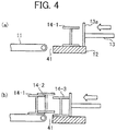
- a gap 41 between a rotary belt 11 serving as a stacking platform and transferring platforms 12 at an end of the rotary belt 11 facing a transferring platform 12.
- a flange of the second H-shaped steel product 14-2 is loaded over a flange of the H-shaped steel product 14-1, and both of the H-shaped steel products are then stacked.
- a space of the gap 41 is formed under the flange of the H-shaped steel product 14-2.
- a flange of the third H-shaped steel product 14-3 to be transferred next can easily enter into under the flange of the preceding H-shaped steel product 14-2, allowing for smooth stacking.
- a roller as an intervening member 9 as described below is provided at the gap between the stacking platform 1 and the transferring platform 2, shaped steel products can be moved more smoothly.
- the stacking device includes a pushing means 3 for pushing the shaped steel product 4 loaded on the transferring platform 2 toward the stacking platform 1.
- a pushing means 3 for pushing the shaped steel product 4 loaded on the transferring platform 2 toward the stacking platform 1.
- a driving mechanism for pushing a plate-like surface can be used such as a pusher 13 shown in Fig. 3 .
- Publicly known means having a cylinder, a link, a slider crank, and the like, which are powered by air, oil pressure, and a motor, and the like can be used as the driving mechanism.
- the pushing means preferably includes a pushing surface 13a having a height and area large enough for abutting with a flange of the shaped steel product at a side abutting with the shaped steel product.
- the shape of the pushing surface is preferably plate-like so as to correspond to the various height levels of various shaped steel products.
- the transferring platform 2 is arranged so as to face the stacking platform 1, and the intervening member 9 may be provided between the stacking platform 1 and the transferring platform 2 so that the shaped steel product 4 can enter smoothly when entering onto the stacking platform 1 from the transferring platform 2.
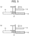
- the intervening member 9 is preferably a rotating roller such as the roller 9 shown in Fig. 3 because a shaped steel product can slide on the roller to be transferred, enabling easy conveyance of the shaped steel product. Further, the intervening member may be non-rotatable. A member with a semicircular cross section or a polygonal cross section having an inclined portion in some region thereof can be used, the member having a flat surface over which a shaped steel product passes.
- the intervening member 9 having a semicircular cross section as shown in Fig. 5(a) may be used.
- the intervening member 9 having an inclined cross section in some region thereof as shown in Fig. 5(b) may be used.
- a material for the main body and surfaces of the intervening member is preferably MC nylon® and the like, which is excellent in scratch resistance and abrasion resistance.
- Shaped steel products which can be stacked using the stacking device according to the present invention are preferably H-shaped steel products each having symmetrical flanges on both sides of the web. Shaped steel products in other forms can also be used such as I-shaped steel products each having a cross-sectional shape similar to that of an H-shaped steel product.
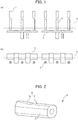
- Fig. 1 shows a specific example of the stacking device according to the present invention. Shown is equipment including two stacking devices, the stacking devices each including three rotary belts (stacking platforms 1), three stacking rollers (transferring platforms 2), and one pusher (pushing means 3). A plate-like member which can pass through between the transferring platforms is provided in the pusher.
- the H-shaped steel product 4 has been brought in from a storage site thereof (not shown) to the transferring platforms 2, and spans and lies on the transferring platforms 2 of the two stacking devices, and is ready for the procedure.
- Fig. 2 is a schematic view showing a specific example of the transferring platform 2 according to the present invention.
- the transferring platform 2 is a polygonal cylinder having a cross-sectional shape of a rectangle with chamfered corners, and is rotatable. Further, it includes the first loading surface 5 having a flat portion and the second loading surface 6 having the flat portion 7 and the inclined portion 8. Rotation of the polygonal cylinder by 90 degrees allows for the selection of the first loading surface 5 or the second loading surface 6, and also allows for repeated use.
- Fig. 3 shows a process for stacking by using the stacking device according to the present invention.
- the stacking device according to the present invention includes the rotary belt 11 which corresponds to the stacking platform, the stacking roller 12 which corresponds to the transferring platform, the pusher 13 which corresponds to the pushing means, and the roller 9 which corresponds to the intervening member.
- the stacking roller 12 is arranged so that the first loading surface 15 having a flat portion is turned to be the upper surface.
- the first H-shaped steel product 14-1 to be stacked is loaded on the first loading surface 15, and ready for the following step.
- the pusher 13 moves toward the H-shaped steel product on the stacking roller 12 as shown in Fig. 3(a) .
- the pusher 13 moves so as to push the H-shaped steel product 14-1 toward the rotary belt 11.
- the surface 13a on which the pusher 13 makes contact with the H-shaped steel product has a height and area large enough for pushing both of the flanges of the H-shaped steel product.
- the first H-shaped steel product 14-1 passes over the roller 9, and is transferred onto the rotary belt 11 where it is loaded on the roller 9 and the rotary belt 11.
- the first loading surface 15 of the transferring platform is arranged so that the height level of an end of the loading surface 15 facing the rotary belt 11 is positioned below the loading surface of the rotary belt 11.
- the above end of the loading surface 15 may simply be positioned below the loading surface of the rotary belt 11 by the thickness of the flange of the H-shaped steel product.
- the shaped steel product which moves to the rotary belt from the transferring platform can slidably pass through on the roller-like intervening member. Therefore, the height of the transferring platform which is set outside the range of the flange thickness will not cause a problem.
- the stacking roller 12 which corresponds to the transferring platform is allowed to rotate so that the second loading surface 16 having the flat portion 7 and the inclined portion 8 is turned to the upper side.
- the second loading surface 16 of the transferring platform is arranged so that the height level of an end of the inclined portion of the loading surface 16 facing the rotary belt 11 is positioned above the loading surface of the rotary belt 11.
- the second H-shaped steel product 14-2 is placed on the flat portion of the second loading surface 16. Then, the second H-shaped steel product 14-2 is pushed with the pusher 13. The H-shaped steel product 14-2 moves along the surface of the inclined portion of the second loading surface 16 as shown in Fig. 3(d) . At this time, the pushing surface 13a of the pusher makes contact with the upper flange of the second H-shaped steel product 14-2 only, and then moves so as to further push the H-shaped steel product. Then, the flange of the second H-shaped steel product 14-2 which has crossed over the inclined portion makes contact with the web of the preceding first H-shaped steel product 14-1.
- the second H-shaped steel product 14-2 continues to push the first H-shaped steel product 14-1 with which the second H-shaped steel product 14-2 has made contact.
- the preceding first H-shaped steel product 14-1 moves along with a belt of the rotary belt 11, and both of the H-shaped steel products are arranged such that the flange of the second H-shaped steel product 14-2 is loaded on the flange of the H-shaped steel product 14-1 as shown in Fig. 3(e) .
- the stacking roller 12 is rotated and arranged so that the first loading surface 15 having a flat portion is turned to be the upper side.
- the height level of the first loading surface 15 can be arranged in a similar way as shown in Fig. 3 (a) .
- the height level of the first loading surface 15 is arranged at a still lower position, depending on the extent of the downward inclination of the flanges of the preceding H-shaped steel product 14-2 as shown in Fig. 3(f) , a flange of the third H-shaped steel product 14-3 can easily enter into under the flange of preceding H-shaped steel product 14-2.
- the third shaped steel product 14-3 is placed on the transferring platform. Then, the third H-shaped steel product 14-3 is pushed with the pusher 13.
- a flange of the third H-shaped steel product 14-3 enters into under the flange of the second H-shaped steel product 14-2.
- the first loading surface 15 of the stacking roller 12 is selected when an odd numbered H-shaped steel product is transferred, and the second loading surface 16 of the stacking roller 12 is selected when an even numbered H-shaped steel product is transferred.
Landscapes
- Engineering & Computer Science (AREA)
- Mechanical Engineering (AREA)
- Stacking Of Articles And Auxiliary Devices (AREA)
Claims (6)
- Stapelvorrichtung zum Stapeln einer Vielzahl von Formstahlprodukten, aufweisend:eine Stapelplattform (1, 11), die mit den Formstahlprodukten (4, 14-1, 14-2,14-3) in gestapelter Form beladen wird;eine Übergabeplattform (2, 12) mit verschiedenen Beladeoberflächen, die mit zumindest einem der Formstahlprodukte (4, 14-1, 14-2,14-3) beladen wird, das an die Stapelplattform (1, 11) übergeben wird; undein Verschiebemittel (3, 13), um das zumindest eine Formstahlprodukt (4, 14-1, 14-2,14-3), das auf der Übergabeplattform (2, 12) liegt, entlang einer Verschieberichtung zur Stapelplattform (1, 11) zu schieben,dadurch gekennzeichnet, dassdie Übergabeplattform (2, 12) ein rotierender Körper ist, der um eine Achse drehbar ist, die parallel zur Verschieberichtung ist, entlang derer das Verschiebemittel schiebt, und der auf ihrem Umfang eine erste Beladeoberfläche (5, 15) mit einem ebenen Bereich (7) und eine zweite Beladeoberfläche (6, 16) mit einem ebenen Bereich (7) und einem geneigten Bereich (8) aufweist, wobei der ebene Bereich (7) und der geneigte Bereich (8) entlang der Verschieberichtung ausgestaltet sind, der geneigte Bereich (8) auf einer Seite ausgestaltet ist, die zur Stapelplattform (1, 11) zeigt, wobei die erste und zweite Beladeoberfläche (5, 15; 6, 16) zum Beladen mit zumindest einem der zu übergebenden Formstahlprodukte (4, 14-1, 14-2,14-3) auswählbar ist, entsprechend der Reihenfolge in der die Formstahlprodukte (4, 14-1, 14-2,14-3) verschoben werden.
- Stapelvorrichtung zum Stapeln von Formstahlprodukten (4, 14-1, 14-2,14-3) gemäß Anspruch 1, wobei die zweite Beladeoberfläche (6, 16) so angeordnet ist, dass die Höhe des geneigten Bereichs (8) auf der Seite, die zur Stapelplattform zeigt, bei oder über der Stärke eines Bunds des zumindest einen der Formstahlprodukte (4, 14-1, 14-2,14-3) angeordnet ist, das auf der Stapelplattform (1, 11) geladen ist.
- Stapelvorrichtung zum Stapeln von Formstahlprodukten (4, 14-1, 14-2,14-3) gemäß Anspruch 1 oder 2, wobei bei der Übergabeplattform (2, 12) die erste Beladeoberfläche (5, 15) ausgewählt werden kann, wenn zumindest eines der ungradzahligen Formstahlprodukte (4, 14-1, 14-2,14-3) übergeben wird und die zweite Beladeoberfläche (6, 16) ausgewählt werden kann, wenn zumindest eines der gradzahligen Formstahlprodukte (4, 14-1, 14-2,14-3) übergeben wird.
- Stapelvorrichtung zum Stapeln von Formstahlprodukten (4, 14-1, 14-2,14-3) gemäß einem der Ansprüche 1 bis 3, wobei der rotierende Körper eine Vielzahl von ersten Beladeoberflächen (5, 15) und / oder zweiten Beladeoberflächen (6, 16) aufweist.
- Stapelvorrichtung zum Stapeln von Formstahlprodukten (4, 14-1, 14-2,14-3) gemäß einem der Ansprüche 1 bis 4, wobei ein eingreifendes Teil (9) zwischen der Stapelplattform (1, 11) und der Übergabeplattform (2, 12) vorgesehen ist.
- Verwendung einer Stapelvorrichtung gemäß einem der Ansprüche 1 bis 5 zum Stapeln einer Vielzahl von Formstahlprodukten.
Applications Claiming Priority (2)
| Application Number | Priority Date | Filing Date | Title |
|---|---|---|---|
| JP2015004269A JP6128612B2 (ja) | 2015-01-13 | 2015-01-13 | 形鋼のパイリング装置 |
| PCT/JP2016/050783 WO2016114284A1 (ja) | 2015-01-13 | 2016-01-13 | 形鋼のパイリング装置 |
Publications (4)
| Publication Number | Publication Date |
|---|---|
| EP3246276A1 EP3246276A1 (de) | 2017-11-22 |
| EP3246276A4 EP3246276A4 (de) | 2018-02-14 |
| EP3246276B1 true EP3246276B1 (de) | 2019-05-01 |
| EP3246276B8 EP3246276B8 (de) | 2019-06-26 |
Family
ID=56405826
Family Applications (1)
| Application Number | Title | Priority Date | Filing Date |
|---|---|---|---|
| EP16737355.4A Active EP3246276B8 (de) | 2015-01-13 | 2016-01-13 | Formstahlstapelvorrichtung |
Country Status (16)
| Country | Link |
|---|---|
| US (1) | US10160610B2 (de) |
| EP (1) | EP3246276B8 (de) |
| JP (1) | JP6128612B2 (de) |
| KR (1) | KR101825338B1 (de) |
| CN (1) | CN107428479B (de) |
| AU (1) | AU2016207512B2 (de) |
| BR (1) | BR112017014890A2 (de) |
| CA (1) | CA2973461C (de) |
| ES (1) | ES2735951T3 (de) |
| MX (1) | MX362500B (de) |
| MY (1) | MY189190A (de) |
| NZ (1) | NZ733663A (de) |
| PH (1) | PH12017501263A1 (de) |
| RU (1) | RU2642212C1 (de) |
| TW (1) | TWI659915B (de) |
| WO (1) | WO2016114284A1 (de) |
Families Citing this family (5)
| Publication number | Priority date | Publication date | Assignee | Title |
|---|---|---|---|---|
| CN109353827B (zh) * | 2018-11-22 | 2020-10-23 | 江苏环信机械工程有限公司 | 一种轨道钢自动精确定距编组方法 |
| CN111003355B (zh) * | 2019-12-26 | 2021-10-29 | 深圳市新元特钢有限公司 | 一种钢材制造加工码垛方法 |
| CN118083592A (zh) * | 2024-04-15 | 2024-05-28 | 山东钢铁股份有限公司 | 一种钢材堆垛机构 |
| KR102770287B1 (ko) | 2024-05-09 | 2025-02-20 | 에이치와이 주식회사 | 선반용 로드빔 자동 적재 장치 |
| CN119734990B (zh) * | 2024-11-12 | 2025-10-28 | 江阴大地装备股份有限公司 | 轨道钢码垛前排钢装置 |
Family Cites Families (27)
| Publication number | Priority date | Publication date | Assignee | Title |
|---|---|---|---|---|
| US3168183A (en) * | 1963-02-27 | 1965-02-02 | United States Steel Corp | Kickout device |
| US3381828A (en) * | 1966-02-07 | 1968-05-07 | Robert T. Sheehan | Filled-bag stacking palletizer |
| JPS4626739Y1 (de) * | 1966-02-14 | 1971-09-14 | ||
| JPS5333824B2 (de) * | 1973-05-04 | 1978-09-16 | ||
| SU557020A1 (ru) * | 1973-07-09 | 1977-05-05 | Днепропетровский Филиал Центрального Научно-Исследовательского И Проектно-Го Института Строительных Металлоконструкций | Пакетировщик уголкового проката |
| JPS5348459Y2 (de) * | 1974-07-30 | 1978-11-20 | ||
| JPS5396785U (de) * | 1977-01-07 | 1978-08-05 | ||
| JPS55109622U (de) * | 1979-01-23 | 1980-08-01 | ||
| SU986842A1 (ru) * | 1981-07-31 | 1983-01-07 | Колпинское отделение Всесоюзного научно-исследовательского и проектно-конструкторского института металлургического машиностроения Научно-производственного объединения "ВНИИМЕТМАШ" | Устройство дл формировани пакета проката |
| JPS60236928A (ja) | 1984-05-09 | 1985-11-25 | Toshiba Corp | 形鋼材のパイリング装置 |
| CN87215315U (zh) * | 1987-11-04 | 1988-08-24 | 杭州卷烟厂 | 叠箱机 |
| SU1572954A1 (ru) * | 1988-04-20 | 1990-06-23 | Производственное объединение "Уралмаш" | Устройство дл послойной укладки изделий в пакет |
| JPH0679937B2 (ja) * | 1989-05-01 | 1994-10-12 | 新日本製鐵株式会社 | H形鋼の組み込み装置 |
| CN2114643U (zh) * | 1991-08-19 | 1992-09-02 | 重庆钢铁公司 | 一种液压型钢堆垛机 |
| JP3370763B2 (ja) * | 1994-01-10 | 2003-01-27 | 滝川工業株式会社 | 長尺材の組合せ装置 |
| JP3423683B2 (ja) * | 2000-11-10 | 2003-07-07 | 川崎重工業株式会社 | 形鋼のパイリング装置およびパイリング方法 |
| JP2002173225A (ja) * | 2000-12-08 | 2002-06-21 | Nippon Steel Corp | H形鋼の組み込み装置 |
| CN2666862Y (zh) * | 2003-12-25 | 2004-12-29 | 天津港第四港埠公司 | 原木堆码整端机 |
| CN201095544Y (zh) * | 2007-07-26 | 2008-08-06 | 中国恩菲工程技术有限公司 | 锌锭翻转机构 |
| CN201538591U (zh) * | 2009-10-15 | 2010-08-04 | 宝山钢铁股份有限公司 | 自动有序堆管装置 |
| CN201737476U (zh) * | 2010-07-23 | 2011-02-09 | 中国国际海运集装箱(集团)股份有限公司 | 一种堆码装置 |
| DE102011084018A1 (de) * | 2011-10-05 | 2013-04-11 | Loesch Verpackungstechnik Gmbh | Verfahren und Vorrichtung zum Fördern von streifenförmigen oder plattenförmigen Produkten |
| CN202481766U (zh) * | 2012-03-28 | 2012-10-10 | 天津市友发德众钢管有限公司 | 一种钢管自动排管装置 |
| US8721254B1 (en) * | 2012-06-22 | 2014-05-13 | Mill Innovations & Design, LLC | Method for stacking beams |
| CN203612656U (zh) * | 2013-12-09 | 2014-05-28 | 天津市金万方钢结构有限公司 | 一种h型钢叠放装置 |
| CN203833090U (zh) * | 2014-05-16 | 2014-09-17 | 安阳中泰管业有限公司 | 钢管自动输送打包装置 |
| AR099633A1 (es) * | 2014-05-27 | 2016-08-10 | The Bradbury Co Inc | Línea automática de empaque para perfiles de sección c y u |
-
2015
- 2015-01-13 JP JP2015004269A patent/JP6128612B2/ja not_active Expired - Fee Related
-
2016
- 2016-01-13 KR KR1020177022371A patent/KR101825338B1/ko not_active Expired - Fee Related
- 2016-01-13 MY MYPI2017001015A patent/MY189190A/en unknown
- 2016-01-13 US US15/543,380 patent/US10160610B2/en not_active Expired - Fee Related
- 2016-01-13 RU RU2017127205A patent/RU2642212C1/ru not_active IP Right Cessation
- 2016-01-13 WO PCT/JP2016/050783 patent/WO2016114284A1/ja not_active Ceased
- 2016-01-13 AU AU2016207512A patent/AU2016207512B2/en not_active Ceased
- 2016-01-13 EP EP16737355.4A patent/EP3246276B8/de active Active
- 2016-01-13 CA CA2973461A patent/CA2973461C/en not_active Expired - Fee Related
- 2016-01-13 TW TW105100925A patent/TWI659915B/zh not_active IP Right Cessation
- 2016-01-13 NZ NZ733663A patent/NZ733663A/en not_active IP Right Cessation
- 2016-01-13 MX MX2017009090A patent/MX362500B/es active IP Right Grant
- 2016-01-13 BR BR112017014890-0A patent/BR112017014890A2/pt active Search and Examination
- 2016-01-13 ES ES16737355T patent/ES2735951T3/es active Active
- 2016-01-13 CN CN201680005395.1A patent/CN107428479B/zh not_active Expired - Fee Related
-
2017
- 2017-07-10 PH PH12017501263A patent/PH12017501263A1/en unknown
Non-Patent Citations (1)
| Title |
|---|
| None * |
Also Published As
| Publication number | Publication date |
|---|---|
| MX2017009090A (es) | 2018-03-01 |
| RU2642212C1 (ru) | 2018-01-24 |
| PH12017501263A1 (en) | 2018-02-05 |
| EP3246276B8 (de) | 2019-06-26 |
| WO2016114284A1 (ja) | 2016-07-21 |
| JP2016130148A (ja) | 2016-07-21 |
| TW201637975A (zh) | 2016-11-01 |
| CN107428479A (zh) | 2017-12-01 |
| MX362500B (es) | 2019-01-21 |
| EP3246276A1 (de) | 2017-11-22 |
| KR20170108038A (ko) | 2017-09-26 |
| US10160610B2 (en) | 2018-12-25 |
| CA2973461C (en) | 2017-11-07 |
| NZ733663A (en) | 2018-08-31 |
| TWI659915B (zh) | 2019-05-21 |
| BR112017014890A2 (pt) | 2018-06-19 |
| US20180002117A1 (en) | 2018-01-04 |
| EP3246276A4 (de) | 2018-02-14 |
| AU2016207512B2 (en) | 2017-08-31 |
| CA2973461A1 (en) | 2016-07-21 |
| AU2016207512A1 (en) | 2017-07-27 |
| ES2735951T3 (es) | 2019-12-20 |
| JP6128612B2 (ja) | 2017-05-17 |
| MY189190A (en) | 2022-01-31 |
| CN107428479B (zh) | 2018-11-09 |
| KR101825338B1 (ko) | 2018-02-02 |
Similar Documents
| Publication | Publication Date | Title |
|---|---|---|
| EP3246276B1 (de) | Formstahlstapelvorrichtung | |
| AU2007221802B2 (en) | Device for lifting a layer consisting of a plurality of containers or the like | |
| US20140369800A1 (en) | Palletiser | |
| EP1321396A1 (de) | Maschine zum Palettisieren | |
| US9573772B2 (en) | Conveyor system with roller assemblies | |
| US10144596B2 (en) | System and method for forming and moving an article array | |
| EP3141515A1 (de) | Behälteranhabende/-herablassende fördervorrichtung | |
| EP3448788A1 (de) | Vorrichtung zum beladen eines laderaums | |
| KR20170020024A (ko) | 상자 적재 장치 및 상자 적재 방법 | |
| DE1901851B2 (de) | Einrichtung fuer den transport von vorbrammen in walzwerken | |
| US20160325944A1 (en) | System and method for loading/unloading article array head | |
| CN109607134A (zh) | 物料输送装置及具有其的码垛机 | |
| JP5662016B2 (ja) | 棒鋼横移し装置 | |
| US20210331879A1 (en) | Palletising Device and Method for Operating a Palletising Device | |
| CN118565213A (zh) | 一种箱式电炉 |
Legal Events
| Date | Code | Title | Description |
|---|---|---|---|
| STAA | Information on the status of an ep patent application or granted ep patent |
Free format text: STATUS: THE INTERNATIONAL PUBLICATION HAS BEEN MADE |
|
| PUAI | Public reference made under article 153(3) epc to a published international application that has entered the european phase |
Free format text: ORIGINAL CODE: 0009012 |
|
| STAA | Information on the status of an ep patent application or granted ep patent |
Free format text: STATUS: REQUEST FOR EXAMINATION WAS MADE |
|
| 17P | Request for examination filed |
Effective date: 20170804 |
|
| AK | Designated contracting states |
Kind code of ref document: A1 Designated state(s): AL AT BE BG CH CY CZ DE DK EE ES FI FR GB GR HR HU IE IS IT LI LT LU LV MC MK MT NL NO PL PT RO RS SE SI SK SM TR |
|
| AX | Request for extension of the european patent |
Extension state: BA ME |
|
| A4 | Supplementary search report drawn up and despatched |
Effective date: 20180115 |
|
| RIC1 | Information provided on ipc code assigned before grant |
Ipc: B65G 57/09 20060101ALI20180109BHEP Ipc: B65G 57/18 20060101AFI20180109BHEP |
|
| DAV | Request for validation of the european patent (deleted) | ||
| DAX | Request for extension of the european patent (deleted) | ||
| GRAP | Despatch of communication of intention to grant a patent |
Free format text: ORIGINAL CODE: EPIDOSNIGR1 |
|
| STAA | Information on the status of an ep patent application or granted ep patent |
Free format text: STATUS: GRANT OF PATENT IS INTENDED |
|
| INTG | Intention to grant announced |
Effective date: 20181123 |
|
| GRAS | Grant fee paid |
Free format text: ORIGINAL CODE: EPIDOSNIGR3 |
|
| GRAA | (expected) grant |
Free format text: ORIGINAL CODE: 0009210 |
|
| STAA | Information on the status of an ep patent application or granted ep patent |
Free format text: STATUS: THE PATENT HAS BEEN GRANTED |
|
| AK | Designated contracting states |
Kind code of ref document: B1 Designated state(s): AL AT BE BG CH CY CZ DE DK EE ES FI FR GB GR HR HU IE IS IT LI LT LU LV MC MK MT NL NO PL PT RO RS SE SI SK SM TR |
|
| REG | Reference to a national code |
Ref country code: GB Ref legal event code: FG4D |
|
| REG | Reference to a national code |
Ref country code: AT Ref legal event code: REF Ref document number: 1126648 Country of ref document: AT Kind code of ref document: T Effective date: 20190515 Ref country code: CH Ref legal event code: EP |
|
| REG | Reference to a national code |
Ref country code: DE Ref legal event code: R096 Ref document number: 602016013283 Country of ref document: DE |
|
| REG | Reference to a national code |
Ref country code: IE Ref legal event code: FG4D |
|
| REG | Reference to a national code |
Ref country code: CH Ref legal event code: PK Free format text: BERICHTIGUNG B8 |
|
| RAP2 | Party data changed (patent owner data changed or rights of a patent transferred) |
Owner name: NIPPON STEEL NISSHIN CO., LTD. |
|
| REG | Reference to a national code |
Ref country code: DE Ref legal event code: R082 Ref document number: 602016013283 Country of ref document: DE Representative=s name: FROHWITTER PATENT- UND RECHTSANWAELTE, DE |
|
| REG | Reference to a national code |
Ref country code: NL Ref legal event code: MP Effective date: 20190501 |
|
| REG | Reference to a national code |
Ref country code: LT Ref legal event code: MG4D |
|
| PG25 | Lapsed in a contracting state [announced via postgrant information from national office to epo] |
Ref country code: FI Free format text: LAPSE BECAUSE OF FAILURE TO SUBMIT A TRANSLATION OF THE DESCRIPTION OR TO PAY THE FEE WITHIN THE PRESCRIBED TIME-LIMIT Effective date: 20190501 Ref country code: AL Free format text: LAPSE BECAUSE OF FAILURE TO SUBMIT A TRANSLATION OF THE DESCRIPTION OR TO PAY THE FEE WITHIN THE PRESCRIBED TIME-LIMIT Effective date: 20190501 Ref country code: PT Free format text: LAPSE BECAUSE OF FAILURE TO SUBMIT A TRANSLATION OF THE DESCRIPTION OR TO PAY THE FEE WITHIN THE PRESCRIBED TIME-LIMIT Effective date: 20190901 Ref country code: NO Free format text: LAPSE BECAUSE OF FAILURE TO SUBMIT A TRANSLATION OF THE DESCRIPTION OR TO PAY THE FEE WITHIN THE PRESCRIBED TIME-LIMIT Effective date: 20190801 Ref country code: SE Free format text: LAPSE BECAUSE OF FAILURE TO SUBMIT A TRANSLATION OF THE DESCRIPTION OR TO PAY THE FEE WITHIN THE PRESCRIBED TIME-LIMIT Effective date: 20190501 Ref country code: HR Free format text: LAPSE BECAUSE OF FAILURE TO SUBMIT A TRANSLATION OF THE DESCRIPTION OR TO PAY THE FEE WITHIN THE PRESCRIBED TIME-LIMIT Effective date: 20190501 Ref country code: LT Free format text: LAPSE BECAUSE OF FAILURE TO SUBMIT A TRANSLATION OF THE DESCRIPTION OR TO PAY THE FEE WITHIN THE PRESCRIBED TIME-LIMIT Effective date: 20190501 Ref country code: NL Free format text: LAPSE BECAUSE OF FAILURE TO SUBMIT A TRANSLATION OF THE DESCRIPTION OR TO PAY THE FEE WITHIN THE PRESCRIBED TIME-LIMIT Effective date: 20190501 |
|
| PG25 | Lapsed in a contracting state [announced via postgrant information from national office to epo] |
Ref country code: BG Free format text: LAPSE BECAUSE OF FAILURE TO SUBMIT A TRANSLATION OF THE DESCRIPTION OR TO PAY THE FEE WITHIN THE PRESCRIBED TIME-LIMIT Effective date: 20190801 Ref country code: GR Free format text: LAPSE BECAUSE OF FAILURE TO SUBMIT A TRANSLATION OF THE DESCRIPTION OR TO PAY THE FEE WITHIN THE PRESCRIBED TIME-LIMIT Effective date: 20190802 Ref country code: RS Free format text: LAPSE BECAUSE OF FAILURE TO SUBMIT A TRANSLATION OF THE DESCRIPTION OR TO PAY THE FEE WITHIN THE PRESCRIBED TIME-LIMIT Effective date: 20190501 Ref country code: LV Free format text: LAPSE BECAUSE OF FAILURE TO SUBMIT A TRANSLATION OF THE DESCRIPTION OR TO PAY THE FEE WITHIN THE PRESCRIBED TIME-LIMIT Effective date: 20190501 |
|
| REG | Reference to a national code |
Ref country code: AT Ref legal event code: MK05 Ref document number: 1126648 Country of ref document: AT Kind code of ref document: T Effective date: 20190501 |
|
| REG | Reference to a national code |
Ref country code: ES Ref legal event code: FG2A Ref document number: 2735951 Country of ref document: ES Kind code of ref document: T3 Effective date: 20191220 |
|
| PG25 | Lapsed in a contracting state [announced via postgrant information from national office to epo] |
Ref country code: IS Free format text: LAPSE BECAUSE OF FAILURE TO SUBMIT A TRANSLATION OF THE DESCRIPTION OR TO PAY THE FEE WITHIN THE PRESCRIBED TIME-LIMIT Effective date: 20190901 |
|
| PG25 | Lapsed in a contracting state [announced via postgrant information from national office to epo] |
Ref country code: EE Free format text: LAPSE BECAUSE OF FAILURE TO SUBMIT A TRANSLATION OF THE DESCRIPTION OR TO PAY THE FEE WITHIN THE PRESCRIBED TIME-LIMIT Effective date: 20190501 Ref country code: AT Free format text: LAPSE BECAUSE OF FAILURE TO SUBMIT A TRANSLATION OF THE DESCRIPTION OR TO PAY THE FEE WITHIN THE PRESCRIBED TIME-LIMIT Effective date: 20190501 Ref country code: DK Free format text: LAPSE BECAUSE OF FAILURE TO SUBMIT A TRANSLATION OF THE DESCRIPTION OR TO PAY THE FEE WITHIN THE PRESCRIBED TIME-LIMIT Effective date: 20190501 Ref country code: RO Free format text: LAPSE BECAUSE OF FAILURE TO SUBMIT A TRANSLATION OF THE DESCRIPTION OR TO PAY THE FEE WITHIN THE PRESCRIBED TIME-LIMIT Effective date: 20190501 Ref country code: SK Free format text: LAPSE BECAUSE OF FAILURE TO SUBMIT A TRANSLATION OF THE DESCRIPTION OR TO PAY THE FEE WITHIN THE PRESCRIBED TIME-LIMIT Effective date: 20190501 Ref country code: CZ Free format text: LAPSE BECAUSE OF FAILURE TO SUBMIT A TRANSLATION OF THE DESCRIPTION OR TO PAY THE FEE WITHIN THE PRESCRIBED TIME-LIMIT Effective date: 20190501 |
|
| REG | Reference to a national code |
Ref country code: DE Ref legal event code: R097 Ref document number: 602016013283 Country of ref document: DE |
|
| PG25 | Lapsed in a contracting state [announced via postgrant information from national office to epo] |
Ref country code: SM Free format text: LAPSE BECAUSE OF FAILURE TO SUBMIT A TRANSLATION OF THE DESCRIPTION OR TO PAY THE FEE WITHIN THE PRESCRIBED TIME-LIMIT Effective date: 20190501 |
|
| PLBE | No opposition filed within time limit |
Free format text: ORIGINAL CODE: 0009261 |
|
| STAA | Information on the status of an ep patent application or granted ep patent |
Free format text: STATUS: NO OPPOSITION FILED WITHIN TIME LIMIT |
|
| PG25 | Lapsed in a contracting state [announced via postgrant information from national office to epo] |
Ref country code: TR Free format text: LAPSE BECAUSE OF FAILURE TO SUBMIT A TRANSLATION OF THE DESCRIPTION OR TO PAY THE FEE WITHIN THE PRESCRIBED TIME-LIMIT Effective date: 20190501 |
|
| 26N | No opposition filed |
Effective date: 20200204 |
|
| PG25 | Lapsed in a contracting state [announced via postgrant information from national office to epo] |
Ref country code: PL Free format text: LAPSE BECAUSE OF FAILURE TO SUBMIT A TRANSLATION OF THE DESCRIPTION OR TO PAY THE FEE WITHIN THE PRESCRIBED TIME-LIMIT Effective date: 20190501 |
|
| PGFP | Annual fee paid to national office [announced via postgrant information from national office to epo] |
Ref country code: ES Payment date: 20200221 Year of fee payment: 5 Ref country code: GB Payment date: 20200124 Year of fee payment: 5 Ref country code: DE Payment date: 20200121 Year of fee payment: 5 Ref country code: IT Payment date: 20200131 Year of fee payment: 5 |
|
| PG25 | Lapsed in a contracting state [announced via postgrant information from national office to epo] |
Ref country code: SI Free format text: LAPSE BECAUSE OF FAILURE TO SUBMIT A TRANSLATION OF THE DESCRIPTION OR TO PAY THE FEE WITHIN THE PRESCRIBED TIME-LIMIT Effective date: 20190501 |
|
| PGFP | Annual fee paid to national office [announced via postgrant information from national office to epo] |
Ref country code: FR Payment date: 20200121 Year of fee payment: 5 |
|
| PG25 | Lapsed in a contracting state [announced via postgrant information from national office to epo] |
Ref country code: MC Free format text: LAPSE BECAUSE OF FAILURE TO SUBMIT A TRANSLATION OF THE DESCRIPTION OR TO PAY THE FEE WITHIN THE PRESCRIBED TIME-LIMIT Effective date: 20190501 |
|
| REG | Reference to a national code |
Ref country code: CH Ref legal event code: PL |
|
| REG | Reference to a national code |
Ref country code: BE Ref legal event code: MM Effective date: 20200131 |
|
| PG25 | Lapsed in a contracting state [announced via postgrant information from national office to epo] |
Ref country code: LU Free format text: LAPSE BECAUSE OF NON-PAYMENT OF DUE FEES Effective date: 20200113 |
|
| PG25 | Lapsed in a contracting state [announced via postgrant information from national office to epo] |
Ref country code: CH Free format text: LAPSE BECAUSE OF NON-PAYMENT OF DUE FEES Effective date: 20200131 Ref country code: LI Free format text: LAPSE BECAUSE OF NON-PAYMENT OF DUE FEES Effective date: 20200131 Ref country code: BE Free format text: LAPSE BECAUSE OF NON-PAYMENT OF DUE FEES Effective date: 20200131 |
|
| PG25 | Lapsed in a contracting state [announced via postgrant information from national office to epo] |
Ref country code: IE Free format text: LAPSE BECAUSE OF NON-PAYMENT OF DUE FEES Effective date: 20200113 |
|
| REG | Reference to a national code |
Ref country code: DE Ref legal event code: R119 Ref document number: 602016013283 Country of ref document: DE |
|
| GBPC | Gb: european patent ceased through non-payment of renewal fee |
Effective date: 20210113 |
|
| PG25 | Lapsed in a contracting state [announced via postgrant information from national office to epo] |
Ref country code: FR Free format text: LAPSE BECAUSE OF NON-PAYMENT OF DUE FEES Effective date: 20210131 |
|
| PG25 | Lapsed in a contracting state [announced via postgrant information from national office to epo] |
Ref country code: GB Free format text: LAPSE BECAUSE OF NON-PAYMENT OF DUE FEES Effective date: 20210113 Ref country code: DE Free format text: LAPSE BECAUSE OF NON-PAYMENT OF DUE FEES Effective date: 20210803 |
|
| REG | Reference to a national code |
Ref country code: ES Ref legal event code: FD2A Effective date: 20220422 |
|
| PG25 | Lapsed in a contracting state [announced via postgrant information from national office to epo] |
Ref country code: IT Free format text: LAPSE BECAUSE OF NON-PAYMENT OF DUE FEES Effective date: 20210113 |
|
| PG25 | Lapsed in a contracting state [announced via postgrant information from national office to epo] |
Ref country code: MT Free format text: LAPSE BECAUSE OF FAILURE TO SUBMIT A TRANSLATION OF THE DESCRIPTION OR TO PAY THE FEE WITHIN THE PRESCRIBED TIME-LIMIT Effective date: 20190501 Ref country code: CY Free format text: LAPSE BECAUSE OF FAILURE TO SUBMIT A TRANSLATION OF THE DESCRIPTION OR TO PAY THE FEE WITHIN THE PRESCRIBED TIME-LIMIT Effective date: 20190501 |
|
| PG25 | Lapsed in a contracting state [announced via postgrant information from national office to epo] |
Ref country code: MK Free format text: LAPSE BECAUSE OF FAILURE TO SUBMIT A TRANSLATION OF THE DESCRIPTION OR TO PAY THE FEE WITHIN THE PRESCRIBED TIME-LIMIT Effective date: 20190501 |
|
| PG25 | Lapsed in a contracting state [announced via postgrant information from national office to epo] |
Ref country code: ES Free format text: LAPSE BECAUSE OF NON-PAYMENT OF DUE FEES Effective date: 20210114 |