EP3246284A1 - Dispositif de chargement pour une installation metallurgique - Google Patents
Dispositif de chargement pour une installation metallurgique Download PDFInfo
- Publication number
- EP3246284A1 EP3246284A1 EP16170534.8A EP16170534A EP3246284A1 EP 3246284 A1 EP3246284 A1 EP 3246284A1 EP 16170534 A EP16170534 A EP 16170534A EP 3246284 A1 EP3246284 A1 EP 3246284A1
- Authority
- EP
- European Patent Office
- Prior art keywords
- holding
- container
- charging
- feeding device
- feed
- Prior art date
- Legal status (The legal status is an assumption and is not a legal conclusion. Google has not performed a legal analysis and makes no representation as to the accuracy of the status listed.)
- Withdrawn
Links
- 238000009434 installation Methods 0.000 title 1
- 239000000463 material Substances 0.000 claims abstract description 15
- 238000010891 electric arc Methods 0.000 claims description 3
- 239000000725 suspension Substances 0.000 description 6
- 241000282326 Felis catus Species 0.000 description 3
- 230000033001 locomotion Effects 0.000 description 3
- 229910000831 Steel Inorganic materials 0.000 description 2
- 230000000881 depressing effect Effects 0.000 description 2
- 238000011161 development Methods 0.000 description 2
- 230000018109 developmental process Effects 0.000 description 2
- 230000010355 oscillation Effects 0.000 description 2
- 239000010959 steel Substances 0.000 description 2
- 238000003723 Smelting Methods 0.000 description 1
- 230000002950 deficient Effects 0.000 description 1
- 230000001419 dependent effect Effects 0.000 description 1
- 238000013461 design Methods 0.000 description 1
- 238000006073 displacement reaction Methods 0.000 description 1
- 238000012423 maintenance Methods 0.000 description 1
- 238000004519 manufacturing process Methods 0.000 description 1
- 238000002844 melting Methods 0.000 description 1
- 230000008018 melting Effects 0.000 description 1
- 238000010310 metallurgical process Methods 0.000 description 1
- 238000000034 method Methods 0.000 description 1
- 238000012549 training Methods 0.000 description 1
Images



Classifications
-
- B—PERFORMING OPERATIONS; TRANSPORTING
- B66—HOISTING; LIFTING; HAULING
- B66C—CRANES; LOAD-ENGAGING ELEMENTS OR DEVICES FOR CRANES, CAPSTANS, WINCHES, OR TACKLES
- B66C13/00—Other constructional features or details
- B66C13/04—Auxiliary devices for controlling movements of suspended loads, or preventing cable slack
- B66C13/08—Auxiliary devices for controlling movements of suspended loads, or preventing cable slack for depositing loads in desired attitudes or positions
-
- B—PERFORMING OPERATIONS; TRANSPORTING
- B66—HOISTING; LIFTING; HAULING
- B66C—CRANES; LOAD-ENGAGING ELEMENTS OR DEVICES FOR CRANES, CAPSTANS, WINCHES, OR TACKLES
- B66C17/00—Overhead travelling cranes comprising one or more substantially horizontal girders the ends of which are directly supported by wheels or rollers running on tracks carried by spaced supports
- B66C17/06—Overhead travelling cranes comprising one or more substantially horizontal girders the ends of which are directly supported by wheels or rollers running on tracks carried by spaced supports specially adapted for particular purposes, e.g. in foundries, forges; combined with auxiliary apparatus serving particular purposes
- B66C17/08—Overhead travelling cranes comprising one or more substantially horizontal girders the ends of which are directly supported by wheels or rollers running on tracks carried by spaced supports specially adapted for particular purposes, e.g. in foundries, forges; combined with auxiliary apparatus serving particular purposes for charging treatment chambers, e.g. furnaces, kilns, ovens
-
- C—CHEMISTRY; METALLURGY
- C21—METALLURGY OF IRON
- C21C—PROCESSING OF PIG-IRON, e.g. REFINING, MANUFACTURE OF WROUGHT-IRON OR STEEL; TREATMENT IN MOLTEN STATE OF FERROUS ALLOYS
- C21C5/00—Manufacture of carbon-steel, e.g. plain mild steel, medium carbon steel or cast steel or stainless steel
- C21C5/52—Manufacture of steel in electric furnaces
- C21C5/527—Charging of the electric furnace
-
- F—MECHANICAL ENGINEERING; LIGHTING; HEATING; WEAPONS; BLASTING
- F27—FURNACES; KILNS; OVENS; RETORTS
- F27B—FURNACES, KILNS, OVENS OR RETORTS IN GENERAL; OPEN SINTERING OR LIKE APPARATUS
- F27B3/00—Hearth-type furnaces, e.g. of reverberatory type; Electric arc furnaces ; Tank furnaces
- F27B3/10—Details, accessories or equipment, e.g. dust-collectors, specially adapted for hearth-type furnaces
- F27B3/18—Arrangements of devices for charging
-
- F—MECHANICAL ENGINEERING; LIGHTING; HEATING; WEAPONS; BLASTING
- F27—FURNACES; KILNS; OVENS; RETORTS
- F27D—DETAILS OR ACCESSORIES OF FURNACES, KILNS, OVENS OR RETORTS, IN SO FAR AS THEY ARE OF KINDS OCCURRING IN MORE THAN ONE KIND OF FURNACE
- F27D3/00—Charging; Discharging; Manipulation of charge
- F27D3/0025—Charging or loading melting furnaces with material in the solid state
-
- Y—GENERAL TAGGING OF NEW TECHNOLOGICAL DEVELOPMENTS; GENERAL TAGGING OF CROSS-SECTIONAL TECHNOLOGIES SPANNING OVER SEVERAL SECTIONS OF THE IPC; TECHNICAL SUBJECTS COVERED BY FORMER USPC CROSS-REFERENCE ART COLLECTIONS [XRACs] AND DIGESTS
- Y02—TECHNOLOGIES OR APPLICATIONS FOR MITIGATION OR ADAPTATION AGAINST CLIMATE CHANGE
- Y02P—CLIMATE CHANGE MITIGATION TECHNOLOGIES IN THE PRODUCTION OR PROCESSING OF GOODS
- Y02P10/00—Technologies related to metal processing
- Y02P10/20—Recycling
Definitions
- the invention relates to a feed device for a metallurgical plant, comprising a feed container for receiving feed, in particular for receiving scrap, and a transport device for transporting the feed container, which comprises a holding device for holding the feed container.
- feed containers are also referred to as scrap baskets in smelter plants.
- a feeder of the above-mentioned type makes it possible to transport the feed material from a feedstock reservoir directly to a feed opening of a metallurgical furnace or to initially transport the load to an intermediate container by means of which the feed material can be transported to the feed opening.
- the productivity of a metallurgical plant depends, among other things, on how fast the feed of its furnace can be carried out.
- An object of the invention is to enable a rapid loading of a metallurgical furnace with feed material.
- the charging device according to the invention has a charging container for receiving feed, in particular for receiving scrap.
- the charging device according to the invention has a transport device for transporting the charging container, which comprises a holding device for holding the charging container.
- the transport device has a plurality of the holding device supporting hoisting ropes, which are guided forming a cable duct.
- the invention is based on the consideration that during transport of the charging container by means of the transporting device, in particular during starting and / or stopping, a pendulum movement of the charging container can occur. Failure to wait a sufficiently long time before emptying the hopper until the pendulum motion has subsided may result in damage to the metallurgical plant when the hopper is emptied.
- a cable shaft forming guide of the hoisting ropes then exists when the hoisting ropes are guided such that the hoisting ropes in each case form a plurality of cable strands, in particular supporting cable strands, wherein the cable strands are respectively braced / guided obliquely.
- the term "oblique" can here be understood as deviating from a horizontal or vertical line.
- the hoisting ropes preferably each have at least two cable strands, which are obliquely to each other, in particular V-shaped to each other, out. Furthermore, the cable strands can each be performed crosswise to one of the other cable strands.
- the transport device has eight or more hoisting ropes, which are guided forming a cable shaft. This allows a particularly high rigidity of the transport device can be achieved.
- the charging container may be at least partially round, in particular cylindrical. It is preferred if the feed container is formed at least in sections, in particular on its upper half, square. For example, the feed container may have a polygonal, in particular rectangular shape.
- the transport device is expediently arranged to offset the feed container horizontally, ie to move the feed container along a horizontal direction.
- the Transport device is adapted to raise and lower the hopper, ie to put the hopper in a vertical direction.
- the transport device is designed as a crane. It is particularly preferred if the transport device is designed as a gantry crane or as a bridge crane. Such cranes can, due to their design, transport very large loads and are therefore particularly well suited for transporting heavy (loaded with material to be loaded) hopper.
- the transport device comprises a track unit.
- the transport device comprises a trolley, also called a trolley, which can carry, for example, a hoist.
- the trolley is guided on the track unit trolley.
- the trolley is preferably guided by the track unit.
- the trolley is equipped with one or more cable drums, in particular with two cable drums. Further, it is advantageous if the trolley has one or more motors for driving the cable drum or cable drums.
- the hoisting ropes are attached to the trolley.
- the hoisting ropes can each be attached at one end to a supporting frame of the trolley. With the other end, the hoisting ropes, for example, on the cable drum or - in the case of several cable drums - be attached to one of the cable drums.
- the holding device preferably has several, in particular at least eight, pulleys for deflecting the hoisting ropes.
- the pulleys guide the hoisting ropes.
- the trolley guide elements, in particular Deflection pulleys, for guiding or deflecting the hoisting ropes have.
- the holding device may be, for example, a crane crossmember.
- the holding device comprises a plurality of interconnected beams, in particular a plurality of beams formed integrally with each other.
- the holding device may be formed, inter alia, H-shaped or rectangular.
- the holding device has a plurality of holding hooks.
- the holding device may thus be in particular a hook crosspiece. Further, it is advantageous if the retaining hooks can be hooked in each case on a retaining pin of the charging container.
- the holding device has at least four holding hooks.
- the retaining hooks are not all arranged in a row.
- the retaining hooks form a rectangle. That is, the retaining hooks are preferably arranged at the vertices of a (imaginary) rectangle.
- the use of four retaining hooks allows a 4-point suspension of the hopper, so a suspension of the hopper at four different points. Compared to a 2-point suspension, this can reduce (further) the susceptibility of the hopper to travel during transport, especially during start-up and / or deceleration. Further, with a 4-point suspension, skewing of the hopper in case of uneven loading of the hopper can be avoided.
- the feed container expediently has an outlet opening. About the outlet opening of the hopper can be emptied. Further, it is preferred if the feed container a closure device for Has closing and releasing the outlet opening. Moreover, it is advantageous if the charging container has an actuating mechanism for actuating the closure device.
- the closure device may comprise at least one flap, in particular a bottom flap. According to a preferred embodiment of the invention, the closure device comprises two pivotally mounted bottom flaps.
- the bottom flaps are outwardly opening flaps. To release the outlet opening, the bottom flaps are preferably separated. To close the bottom flaps are preferably merged.
- the bottom flaps are identical or designed substantially identical to each other.
- the bottom flaps can be configured as gripper-shaped half shells.
- the bottom flaps are advantageously arranged symmetrically with respect to a plane of symmetry of the feed container. Further, it is advantageous if the movement of the bottom flaps takes place simultaneously.
- the probability can be reduced that the feed material tilts when opening the closure device.
- the feed container in addition to the outlet opening, expediently has a receiving opening through which the feed material can be introduced into the feed container.
- the receiving opening and the outlet opening are arranged opposite one another.
- the actuating mechanism may include, among other things, at least one cable.
- a cable is a device that can withstand harsh conditions such as metallurgical processes are common, especially high temperatures and / or heavy pollution, can withstand.
- a cable can be realized structurally simple and low maintenance. Consequently, a cable can form a low-cost and reliable (part of) an actuating mechanism.
- the cable expediently has at least one cable which is fastened to the closure device, in particular to one of the bottom flaps.
- the actuating mechanism comprises at least one pulley.
- the aforementioned cable may be designed as a pulley.
- the pulley comprises at least one cable which is attached to the closure device, in particular to one of the bottom flaps.
- the rope of the cable pull or pulley may be, for example, a wire rope, in particular a steel wire rope act. It is preferred if the cable pull or the pulley comprises two cables. One of these ropes can be attached to each of the two bottom flaps of the closure device.
- the pulley can be designed in particular as an inverted pulley (also called reverse pulley). In this way it is possible to use a drive unit with a lower stroke for driving the pulley, which in turn allows compact dimensioning of the drive unit.
- inverted pulley also called reverse pulley
- An inverted pulley may be understood to mean a pulley which is adapted to reduce a (down) stroke to be applied for lifting a load by a predetermined amount. Furthermore, the inverted pulley is expediently adapted to increase a force which is to be applied for lifting the load by the predetermined height. Appropriately, the applied Increases force from inverted pulley by the same factor that the (down) stroke is reduced.
- the feed container may have a linear guide, in particular a sliding guide.
- the pulley in turn may comprise a linearly displaceably mounted on the linear guide slide.
- the carriage is equipped with a reel unit.
- the reel unit may comprise one or more, preferably at least two, pulleys for deflecting the rope or cables of the pulley.
- the pulleys may be rotatably mounted in particular about the same axis of rotation.
- the pulley comprises one or more stationary with respect to a wall of the hopper arranged pulleys for guiding his rope or his ropes.
- the feed container may have several, in particular two, such linear guides.
- the transport device has at least one drive unit, in particular a linear drive, for driving the actuating mechanism.
- the drive unit is arranged so that it can exert a force on the actuating mechanism, in particular on the aforementioned carriage.
- the drive unit is preferably fastened to the holding device, in particular to a bar of the holding device.
- the drive unit can be designed as an integrated element of the transport device. This can be dispensed with a complicated positioning of a separate device for driving the actuating mechanism in the vicinity of the charging container, in particular with each emptying of the charging container.
- the drive unit for example, as a working cylinder, in particular as a hydraulic, pneumatic or Elektrohubzylinder be formed.
- Working cylinders also called lifting cylinders
- the drive unit may comprise a cylinder housing and / or a push rod.
- the drive unit is adapted to move the aforementioned carriage of the pulley, for example by a retraction / extension of its push rod.
- the drive unit is a pushing cylinder, which presses with its push rod indirectly or directly against the aforementioned slide, especially when the push rod (sufficiently far) is extended.
- the carriage can be pressed down.
- the closure device is preferably opened, in particular by their bottom flaps are guided apart.
- the bottom flaps of the closure device are preferably brought together under the influence of the weight force acting on them, thereby closing the closure device or the outlet opening of the charging container.
- the actuating mechanism comprises two pulleys, in particular two pulleys arranged symmetrically with respect to a plane of symmetry of the charging container. In this way, the force required to operate the closure device can be divided between the two pulleys, so that it is sufficient if the respective pulley transfers less force to the closure device.
- the feed container advantageously has a plurality of, in particular at least four, holding pins.
- a holding hook of the holding device can be hooked to the retaining pin.
- the use of four retaining hooks allows a 4-point suspension of the hopper, which as mentioned above is particularly advantageous.
- the retaining pins are arranged in an upper region of the charging container, in particular all at the same height.
- the retaining pins can be arranged, for example, in the region of the corners of the charging container.
- at least two of the retaining pins may be arranged on a first side of the charging container and at least two other of the retaining pins on a second side of the charging container opposite the first side.
- the invention relates to a metallurgical plant.
- the metallurgical plant expediently comprises a metallurgical furnace, in particular a melting furnace, such as an electric arc furnace.
- the metallurgical plant preferably comprises the charging device according to the invention, in particular one of the previously described advantageous developments of the charging device according to the invention.
- the metallurgical furnace has a feed opening through which feed material, in particular scrap, can be introduced into the metallurgical furnace.
- the feed to be transported in the feed hopper of the feeder can for example be introduced directly from the hopper into the metallurgical furnace.
- the metallurgical plant may comprise a further feed tank (hereinafter referred to as intermediate tank) which receives the feedstock from the former hopper and with the aid of which the feedstock is transported (further) to the metallurgical furnace.
- intermediate tank a further feed tank
- Such an intermediate container For example, it can be arranged on a moving unit, by means of which the intermediate container can be moved.
- the metallurgical plant may have a separate drive device for driving the actuating mechanism, in particular for depressing the aforementioned carriage.
- the separate drive device is not permanently attached to the transport device.
- the separate drive device may include, among other things, an arm with a forked portion.
- the separate drive device may for example comprise a working cylinder.
- This separate drive device may be provided in particular instead of the aforementioned drive unit of the transport device.
- the separate drive device may be provided in addition to the drive unit of the transport device.
- the separate drive device can be used, for example, when the drive unit of the transport device is defective.
- FIG. 1 shows a schematic representation of a metallurgical plant 2.
- the metallurgical plant 2 comprises a metallurgical furnace 4, which in the present embodiment is an electric arc furnace.
- the metallurgical furnace 4 is mounted on a (not shown figuratively) support frame and has a feed opening 6, can be introduced through the feed into the oven 4.
- the oven 4 has a lid (not shown in the figure) to which a plurality of electrodes are fastened and which covers the feed opening 6 during operation of the oven 4.
- the metallurgical plant 2 comprises a charging device 8.
- the charging device 8 comprises a charging container 10 for receiving feed material.
- the hopper 10 is a so-called scrap basket, which is used for the transport of steel scrap.
- the charging container 10 has on its upper side a receiving opening 12 and on its underside an outlet opening 14 (cf., for example FIG. 3 ). About the receiving opening 12 of the charging container 10 is loaded with the feed and via the outlet opening 14 of the charging container 10 is emptied.
- the charging container 10 has a closure device 16 for closing and releasing its outlet opening 14.
- the closure device 16 in turn comprises two pivotally mounted bottom flaps 18 (see. 3 to FIG. 7 ), of which in FIG. 1 only one is visible.
- the charging container 10 comprises an actuating mechanism 20 for actuating the closure device 16, ie for moving the two bottom flaps 18 (cf. 3 to FIG. 7 ).
- the charging device 8 has a transport device 22 for transporting the charging container 10.
- the transport device 22 is designed as a crane.
- the transport device 22 comprises a running-rail unit 24 supported on a plurality of supports (not shown in the figure) and a trolley 26 guided on the running-rail unit 24.
- the transport device 22 has a holding device 28 configured as a crane cross-member for holding the charging container 10.
- the holding device 28 is equipped with four retaining hooks 30, which can be hooked in each case on a retaining pin 32 of the charging container 10.
- the four retaining hooks 30 of the holding device 28 are hooked to four retaining pins 32 of the charging container 10 and thus realize with the retaining pin 32 a 4-point suspension of the charging container 10, wherein in FIG. 1 only two of the retaining hooks 30 are visible.
- the transport device 22 has a plurality of the holding device 28 supporting hoisting ropes 34, which are guided a cable shaft 36 training.
- the hoisting ropes 34 connect the holding device 28 to the trolley 26.
- the metallurgical plant 2 comprises an intermediate container 38, which has on its upper side an opening 40, via which the intermediate container 38 can be loaded with feed.
- the feed container 10 is loaded with the feed material at a feedstock reservoir (not shown in the figure). Thereafter, the hopper 10 is transported by means of the transport device 22 from the feedstock reservoir to the intermediate container 38. If the charging container 10 is located above the intermediate container 38, the closure device 16 of the charging container 10 is opened, thereby releasing its outlet opening 14. The charging container 10 is emptied through the outlet opening 14 and the feed material is introduced into the intermediate container 38.
- the intermediate container 38 is arranged on an inclined lift 42 and is intended to receive the feed from the feed container 10 and to transport it to the metallurgical furnace 4 on.
- the intermediate container 38 has an openable flap 44, via which the intermediate container 38 can be emptied, for example by means of a (not shown figuratively) tilting mechanism for tilting the intermediate container 38.
- the charging device 8 could be used to directly feed a metallurgical furnace, that is, without first introducing the charge into an intermediate container.
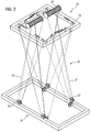
- FIG. 2 shows a part of the transport device 22 in a perspective view, wherein the transport device 22, the holding device 28 and the trolley 26 are shown.
- the trolley 26 comprises a cat frame 78 and two motor-driven cable drums 80, which are arranged on the cat frame 78. Furthermore, the holding device 28 has a A plurality of pulleys 82, which deflect the hoisting ropes 34.
- the hoisting ropes 34 are guided to form a sheave 36.
- the hoisting ropes 34 are each attached at one end to one of the two cable drums 80. With their other end, the hoisting ropes 34 are each attached to the cat frame 78.
- the hoisting ropes 34 each form a plurality of supporting cable strands, which are braced obliquely relative to the vertical.
- Each of the hoisting ropes 34 in this case has a plurality of cable strands, which are guided in a V-shape relative to one another.
- the cable strands are each led crosswise to one of the other cable strands.
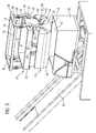
- FIG. 3 shows the intermediate container 38, the hopper 10 and a part of the transport device 22 in a perspective view, wherein the transport device 22, the holding device 28 is shown.
- the aforementioned deflection rollers 82 of the holding device 28 are not shown in this figure.
- FIG. 3 the closure device 16 is shown in the open state. That is, the outlet opening 14 of the charging container 10 is released. Furthermore, all four retaining hooks 30 of the holding device 28 are visible in the illustrated perspective.
- the holding device 28 has a Reckeckige shape.
- the holding device 28 comprises two narrow side bars 46 and two wide side bars 48, which are connected at their ends to the narrow side bars 46. At the narrow side bars 46 are each two of the four retaining hooks 30 of the holding device 28 is attached.
- the charging container 10 is formed angularly above its bottom flaps 18, whereas the bottom flaps 18 are designed as gripper-shaped half shells.
- the aforementioned actuating mechanism 20 comprises two pulley blocks 50. Each of the two pulley blocks 50 comprises two cables 52 (cf. 4 to FIG. 7 ). In addition, the two pulleys 50 are designed as inverted pulleys.
- each of the two pulleys 50 comprises a linearly displaceably mounted carriage 72 with a roller unit 54 which has two deflection rollers 56 rotatably mounted about the same axis of rotation for guiding the cables 52 of the respective pulley block 50 (cf. 4 to FIG. 7 ).
- One of the two slides 72 is mounted on the linear guide 74 of the first narrow side wall 60 of the charging container 10. Whereas the other of the two slides 72 is mounted on the second narrow side wall 62 of the charging container 10. In the closed state of the closure device 16, the carriages 72 are each behind a cover 64 of the charging container 10th
- each of the two pulleys 50 comprises a plurality of stationary arranged, d. H. non-displaceable, pulleys 58 for guiding the ropes 52 of the respective pulley 50th
- the holding device 28 has two integrated drive units 66, which are each set up to drive one of the two hoists 50.
- the two drive units 66 are each a working cylinder, such as a hydraulic, pneumatic or electric lifting cylinder, with a cylinder housing 68 and a push rod 70.
- the two drive units 66 are each attached to one of the narrow side bars 46 of the holding device 28 ,
- the drive units 66 are controlled by means of an electronic control device (not shown in the figure) which has a processor running control software.
- the control device can directly control the drive units 66, for example, in particular if the drive units 66 are designed as electric lift cylinders.
- the control device may indirectly control the drive units 66, in particular if the drive units 66 are used as hydraulic or pneumatic cylinder are executed. Indirect control can for example take place in that the control device controls a pump which influences the position of the respective drive unit 66.
- the charging container 10 has only one pulley 50. On one of the two pulleys 50 of the hopper 10 could therefore be dispensed with in principle.
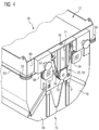
- FIG. 4 shows a perspective view of the hopper 10, in which one of the two pulleys 50 is visible.
- FIG. 4 the closure device 16 is shown in the closed state. Further, the aforementioned cover 64 is not shown, so that the carriage 72 of the pulley 50 is visible with its reel unit 54.
- the charging container 10 has on its upper side for the push rod 70 of the respective drive unit 66 in each case an opening 76.
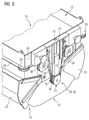
- FIG. 5 also shows a perspective view of the hopper 10, wherein the hopper 10 is shown in the same perspective as in FIG. 4 ,
- FIG. 5 the closure device 16 of the charging container 10 is opened. That is, the bottom flaps 18 are pivoted outwardly, so that the outlet opening 14 of the charging container 10 is released. In this state, the carriage 72 is in a lower position than in the closed state of the closure device 16.
- FIG. 6 shows a side view of the feed container 10.
- FIG. 6 the closure device 16 is shown in the closed state.
- the push rod 70 of the above the carriage 72 arranged drive unit 66 is spaced from the carriage 72.
- the two cables 52 of the pulley 50 are each attached at one of its two ends to a side wall of the charging container 10. With its other end, the two ropes 52 of the pulley 50 are each attached to one of the bottom flaps 18.
- Each of the two cables 52 of the pulley 50 is guided along one of the two deflection rollers 56 of the roller unit 54 of the carriage 72.
- the pulley 50 as mentioned above, equipped with a plurality of non-displaceable pulleys 58 for deflecting the ropes 52.
- the pulleys 56, 58 of the pulley 50 are positioned so or the ropes 52 of the pulley 50 are guided by means of the guide rollers 56, 58 such that a downward displacement of the roller unit 54 causes bottom flaps 18 of the closure device 16 apart or be swung apart.
- the push rod 70 of the drive unit 66 is extended out of its cylinder housing 68 (downwards). As soon as the push rod 70 contacts the carriage 72, the push rod 70 pushes the carriage 72 downwards. By depressing the carriage 72, the bottom flaps 18 of the closure device 16 are guided apart by means of the cables 52 of the pulley 50, so that the outlet opening 14 of the charging container 10 is released (cf. FIG. 7 ).
- the downward stroke which the drive unit 66 must provide (after the push rod 70 contacts the carriage 72) to raise the bottom flaps 18 by a predetermined distance corresponds to approximately half of this predetermined distance.
- the push rod 70 is retracted into the cylinder housing 68.
- the bottom flaps 18 are brought together under the influence of the weight acting on them.
- FIG. 7 also shows a side view of the hopper 10.
- the closure device 16 of the hopper 10 is shown open.
- the push rod 70 of the above the carriage 72 arranged drive unit 66 is extended and presses against the carriage 72 so that the bottom flaps 18 are kept apart by means of the pulley 50.
Landscapes
- Engineering & Computer Science (AREA)
- Mechanical Engineering (AREA)
- General Engineering & Computer Science (AREA)
- Chemical & Material Sciences (AREA)
- Manufacturing & Machinery (AREA)
- Materials Engineering (AREA)
- Metallurgy (AREA)
- Organic Chemistry (AREA)
- Filling Or Emptying Of Bunkers, Hoppers, And Tanks (AREA)
Priority Applications (1)
| Application Number | Priority Date | Filing Date | Title |
|---|---|---|---|
| EP16170534.8A EP3246284A1 (fr) | 2016-05-20 | 2016-05-20 | Dispositif de chargement pour une installation metallurgique |
Applications Claiming Priority (1)
| Application Number | Priority Date | Filing Date | Title |
|---|---|---|---|
| EP16170534.8A EP3246284A1 (fr) | 2016-05-20 | 2016-05-20 | Dispositif de chargement pour une installation metallurgique |
Publications (1)
| Publication Number | Publication Date |
|---|---|
| EP3246284A1 true EP3246284A1 (fr) | 2017-11-22 |
Family
ID=56068728
Family Applications (1)
| Application Number | Title | Priority Date | Filing Date |
|---|---|---|---|
| EP16170534.8A Withdrawn EP3246284A1 (fr) | 2016-05-20 | 2016-05-20 | Dispositif de chargement pour une installation metallurgique |
Country Status (1)
| Country | Link |
|---|---|
| EP (1) | EP3246284A1 (fr) |
Cited By (1)
| Publication number | Priority date | Publication date | Assignee | Title |
|---|---|---|---|---|
| CN114852853A (zh) * | 2022-04-25 | 2022-08-05 | 安徽送变电工程有限公司 | 一种简易行车及其稳定组件 |
Citations (5)
| Publication number | Priority date | Publication date | Assignee | Title |
|---|---|---|---|---|
| DE1265947B (de) * | 1964-07-23 | 1968-04-11 | Maschf Augsburg Nuernberg Ag | Muldenkippkran |
| DE2133536A1 (de) * | 1971-07-06 | 1973-01-25 | Titovi Zavodi Litostroj | Hebezeug mit starrer aufhaengung des lastaufnehmenden organs |
| US4214664A (en) * | 1978-08-24 | 1980-07-29 | The Alliance Machine Company | Crane safety reeving |
| EP2275764A1 (fr) * | 2009-07-06 | 2011-01-19 | Siemens AG | Dispositif destiné au positionnement d'un panier à matériel |
| EP2511221A1 (fr) * | 2011-04-15 | 2012-10-17 | Kranwerke AG Mannheim | Dispositif pour transférer de matière en vrac |
-
2016
- 2016-05-20 EP EP16170534.8A patent/EP3246284A1/fr not_active Withdrawn
Patent Citations (5)
| Publication number | Priority date | Publication date | Assignee | Title |
|---|---|---|---|---|
| DE1265947B (de) * | 1964-07-23 | 1968-04-11 | Maschf Augsburg Nuernberg Ag | Muldenkippkran |
| DE2133536A1 (de) * | 1971-07-06 | 1973-01-25 | Titovi Zavodi Litostroj | Hebezeug mit starrer aufhaengung des lastaufnehmenden organs |
| US4214664A (en) * | 1978-08-24 | 1980-07-29 | The Alliance Machine Company | Crane safety reeving |
| EP2275764A1 (fr) * | 2009-07-06 | 2011-01-19 | Siemens AG | Dispositif destiné au positionnement d'un panier à matériel |
| EP2511221A1 (fr) * | 2011-04-15 | 2012-10-17 | Kranwerke AG Mannheim | Dispositif pour transférer de matière en vrac |
Cited By (1)
| Publication number | Priority date | Publication date | Assignee | Title |
|---|---|---|---|---|
| CN114852853A (zh) * | 2022-04-25 | 2022-08-05 | 安徽送变电工程有限公司 | 一种简易行车及其稳定组件 |
Similar Documents
| Publication | Publication Date | Title |
|---|---|---|
| DE1931043C3 (de) | Palettenentladevorrichtung | |
| DE102014226384B4 (de) | Ladesystem und Ladeverfahren für Schmiedemaschinen | |
| DE1756572A1 (de) | Kran | |
| AT519139B1 (de) | Regalbediengerät und Regallagersystem mit verbesserter Zugänglichkeit und Gewichtsverteilung | |
| EP1106564B1 (fr) | Dispositif de levage pour augmenter la capacité d'un appareil de transbordement pour conteneurs ISO | |
| DE1001645B (de) | Foerdervorrichtung zum Wegfuehren eines bestimmten Lastenstueckes aus einem Stapel | |
| EP1365984B1 (fr) | Depot pour conteneurs vides servant au stockage intermediaire de conteneurs vides iso | |
| DE2044437A1 (de) | Teleskopartige Hebevorrichtung | |
| EP0123846A1 (fr) | Chariot avec dispositif de levage à câble avec amortissement des oscillations pendulaires | |
| DE1943631B2 (de) | Betätigungseinrichtung zum Öffnen und Schließen der Schalen oder Finger eines mit dem Hubseil eines Krans oder Baggers verbundenen Greifers | |
| DE3344261C2 (de) | Vorrichtung zum Auskleiden von metallurgischen Gefäßen | |
| EP0063724B1 (fr) | Dispositif pour attacher un grappin pour bâtiments agricoles à un support mobile au moyen d'un élément flexible | |
| DE19953715C2 (de) | Hallenanordnung | |
| DE4224829C2 (de) | Anordnung zum Entladen und gegebenenfalls Beladen von Güterwagen | |
| DE2103201C3 (de) | Vorrichtung zum Verhindern des Pendeins der Last beim Umschlagen von Frachtbehältern (Containern) | |
| DE2437089A1 (de) | Greiferanordnung fuer hebezeuge | |
| DE4323983C1 (de) | Transportvorrichtung für Geldkassetten | |
| DE1531208B1 (de) | Betaetigungseinrichtung fuer eine Greifzange eines Tiefofenkrans | |
| DE2635387C2 (de) | Kran | |
| DE2114386A1 (de) | Hubeinrichtung für Container | |
| DD141818A1 (de) | Zangenhubeinrichtung mit mehrstraengiger seilanordnung und pendelarmer lastfuehrung | |
| DE2936871C2 (de) | Fütterungsvorrichtung für Vieh | |
| DE2213287C3 (de) | Laufkatze mit Aufhängung des Lastaufnahmemittels zur Minderung des Lastpendeins | |
| DE2751492B2 (de) | Zangenkran mit mindestens einer selbstschließenden, schlitzlosen Last-Greifzange in Form einer sogenannten Bogenzange | |
| DE2232388C3 (de) | An einem Seil hängender Greifer mit angebauter Schalteinrichtung |
Legal Events
| Date | Code | Title | Description |
|---|---|---|---|
| PUAI | Public reference made under article 153(3) epc to a published international application that has entered the european phase |
Free format text: ORIGINAL CODE: 0009012 |
|
| AK | Designated contracting states |
Kind code of ref document: A1 Designated state(s): AL AT BE BG CH CY CZ DE DK EE ES FI FR GB GR HR HU IE IS IT LI LT LU LV MC MK MT NL NO PL PT RO RS SE SI SK SM TR |
|
| AX | Request for extension of the european patent |
Extension state: BA ME |
|
| 17P | Request for examination filed |
Effective date: 20180522 |
|
| RBV | Designated contracting states (corrected) |
Designated state(s): AL AT BE BG CH CY CZ DE DK EE ES FI FR GB GR HR HU IE IS IT LI LT LU LV MC MK MT NL NO PL PT RO RS SE SI SK SM TR |
|
| STAA | Information on the status of an ep patent application or granted ep patent |
Free format text: STATUS: THE APPLICATION IS DEEMED TO BE WITHDRAWN |
|
| 18D | Application deemed to be withdrawn |
Effective date: 20180523 |