EP3246385B1 - Bierzubereiter - Google Patents
Bierzubereiter Download PDFInfo
- Publication number
- EP3246385B1 EP3246385B1 EP17171727.5A EP17171727A EP3246385B1 EP 3246385 B1 EP3246385 B1 EP 3246385B1 EP 17171727 A EP17171727 A EP 17171727A EP 3246385 B1 EP3246385 B1 EP 3246385B1
- Authority
- EP
- European Patent Office
- Prior art keywords
- flow path
- beer
- fermentation tank
- water
- water supply
- Prior art date
- Legal status (The legal status is an assumption and is not a legal conclusion. Google has not performed a legal analysis and makes no representation as to the accuracy of the status listed.)
- Active
Links
Images







Classifications
-
- C—CHEMISTRY; METALLURGY
- C12—BIOCHEMISTRY; BEER; SPIRITS; WINE; VINEGAR; MICROBIOLOGY; ENZYMOLOGY; MUTATION OR GENETIC ENGINEERING
- C12C—BEER; PREPARATION OF BEER BY FERMENTATION; PREPARATION OF MALT FOR MAKING BEER; PREPARATION OF HOPS FOR MAKING BEER
- C12C13/00—Brewing devices, not covered by a single group of C12C1/00 - C12C12/04
- C12C13/10—Home brew equipment
-
- C—CHEMISTRY; METALLURGY
- C12—BIOCHEMISTRY; BEER; SPIRITS; WINE; VINEGAR; MICROBIOLOGY; ENZYMOLOGY; MUTATION OR GENETIC ENGINEERING
- C12C—BEER; PREPARATION OF BEER BY FERMENTATION; PREPARATION OF MALT FOR MAKING BEER; PREPARATION OF HOPS FOR MAKING BEER
- C12C11/00—Fermentation processes for beer
- C12C11/003—Fermentation of beerwort
- C12C11/006—Fermentation tanks therefor
-
- C—CHEMISTRY; METALLURGY
- C12—BIOCHEMISTRY; BEER; SPIRITS; WINE; VINEGAR; MICROBIOLOGY; ENZYMOLOGY; MUTATION OR GENETIC ENGINEERING
- C12C—BEER; PREPARATION OF BEER BY FERMENTATION; PREPARATION OF MALT FOR MAKING BEER; PREPARATION OF HOPS FOR MAKING BEER
- C12C13/00—Brewing devices, not covered by a single group of C12C1/00 - C12C12/04
- C12C13/02—Brew kettles
Definitions
- the present disclosure relates to a beer maker, and more particularly, to a beer maker for brewing beer by fermenting beer materials.
- Customers may purchase ready-made articles brewed and sold by beer brewers, or house beers (or handmade beers) may be brewed by directly fermenting materials of the beers in households or bars.
- house beers may be brewed as compared with ready-made articles.
- the house beers may be brewed suitable for customers' tastes.
- Materials for brewing beer may be water, malt, hops, yeast, fragrance additives, and the like.
- the yeast may be called as leaven, and may be added to malt to ferment the malt. Also, the yeast may assist alcohol and carbonic acid to be generated.
- house beer may include a total of three steps, i.e., a wort producing step, a fermenting step, and a ripening step, and two weeks to three weeks may be required from the wort producing step to the ripening step.
- a mini brewing system comprising a brewing container having a bottom portion, a preferably insulated housing shell, and a head portion.
- the head portion is spaced from the bottom part by the housing shell and arranged substantially parallel to the bottom part.
- the head part has at least one opening wire which temperature adjustment means, in particular cooling elements and heating elements, as well as sieve and filter elements can be arranged in the brewing container.
- the brewing container is configured to be rotatable along its longitudinal axis and independently thereof pivotable.
- WO 2009/017428 A1 relates to a combined brewing system for home or small scale brewing of fermented alcoholic beverages, particularly beer, and to a method of making fermented alcoholic beverages.
- the known brewing system comprises a single pressurizable vessel having means for naturally carbonating the beer to the desired level during fermentation, for collecting and substantially separating any sediment from within the vessel and removing it from the vessel while the vessel is under pressure, means for receiving compressed gas for dispense purposes and for maintaining natural carbonation levels, and a draft dispense draw off mechanism for drawing off the contents of the vessel at a desired pressure.
- the vessel has or is adapted to be coupled with a temperature control system to selectively control the temperature of the contents of the vessel during all stages of processing.
- the known vessel or system is capable of accommodating at least the brewing steps of fermentation, natural carbonation, maturation and draw off so that, in use, the processing is less time consuming and labour intensive compared to other small large scale brewing processes and the risk of contamination of the contents of the vessel by aid and/or undesirable microorganisms during the brewing process is minimized thereby producing an improved quality beverage.
- JP H07 327658 A teaches a further beer brewing machine suitable for small brewing such as brewing in a home.
- CN 2 510 497 Y relates to beer brewing equipment provided with a refrigeration device.
- the upper part of the inner container is provided with a material inlet with a hole lid; a connecting outer shell can be arranged on the bottom board; the wall of the inner container is provided with an electric heater and a temperature measuring tube; the upper supporting leg at the bottom of the inner container is arranged on the supporting board; the supporting board is arranged on the bottom board through lower supporting legs.
- Embodiments also provide a beer maker capable of being compact in size.
- a beer maker including: a fermentation tank; an evaporator disposed at the fermentation tank; and a heat insulating wall surrounding the fermentation tank and the evaporator together. Accordingly, beer can be brewed to an optimum temperature by the evaporator and the heat insulating wall. Further, since the heat insulating wall heat-insulates the fermentation tank and the evaporator together, the beer maker has a simple structure and can be compact in size. The beer maker may be a household appliance. It may have compact size and could be easily transported.
- the beer maker further includes a fermentation tank cover opening/closing an opening formed in the fermentation tank.
- the fermentation tank cover and the fermentation tank constitute a fermentation tank assembly.
- the beer maker may further include a beer brewing pack accommodating beer materials therein.
- the beer brewing pack may be inserted and accommodated in the fermentation tank through the opening.
- the beer maker may further include a heat insulating wall cover surrounding the circumferential surface and top surface of the heat insulating wall.
- An upper through-hole is formed at an upper portion of the heat insulating wall cover.
- a beer maker comprising: an opening/closing valve installed in the supplier entrance flow path to open/close the supplier entrance flow path, the opening/closing valve being located under the capsule accommodation body; and a center cover covering the front of the opening/closing valve.
- a beer maker further comprising: a gas extraction flow path connected to the fermentation tank cover; a pressure sensor installed in the gas extraction flow path; and a gas opening/closing valve opening/closing the gas extraction flow path.
- the fermentation tank cover 114 is used to seal the inside of the fermentation tank 112, and may be disposed at an upper portion of the fermentation tank 112 to cover the opening 111.
- a main flow path connecting part 115 connected to the main flow path 2 may be formed in the fermentation tank cover 114.
- the beer maker may include both of the supplier 3 and the beer brewing pack 12, and the materials for brewing the beer may be distributed and accommodated in the supplier 3 and the beer brewing pack 12. Some materials among the materials for brewing the beer may be accommodated in the beer brewing pack 12, and the other materials may be accommodated in the supplier 3. The other materials accommodated in the supplier 3 may be supplied to the beer brewing pack 12 together with water supplied from the water supply module 5, and be mixed with the some materials accommodated in the beer brewing pack 12.
- a main material essential to brew the beer may be accommodated in the beer brewing pack 12, and additives added to the main material may be accommodated in the supplier 3.
- the additives accommodated in the supplier 3 may be mixed with the water supplied from the water supply module 5 to be supplied to the beer brewing pack 12, and be mixed with the main material accommodated in the beer brewing pack 12.
- the main material accommodated in the beer brewing pack 12 is a material having a larger volume than the other materials, and may be the malt among the malt, the yeast, the hops, and the fragrance additives.
- the additives accommodated in the supplier 3 may be the other materials except the malt among the material for brewing the beer, and be the yeast, the hops, the fragrance additives, and the like.
- the beer maker does not include both of the beer brewing pack 12 and the supplier 3 as described above, but may include only the supplier 3 without any separate beer brewing pack 12.
- All of the materials for brewing the beer may be accommodated in the supplier 3.
- all of the materials accommodated in the supplier 3 may be supplied to the inside of the fermentation tank assembly 11 together with the water supplied from the water supply module 5.
- the main material and the additives may be accommodated together in the supplier 3.
- the main material and additives, which are accommodated in the supplier 3, may be simultaneously supplied to the inside of the fermentation tank assembly 11 or be sequentially supplied with a time difference.
- the beer maker does not include any separate beer brewing pack 12, but may directly inject some materials among the materials for brewing the beer into the fermentation tank assembly 11 and allow the other materials for brewing the beer to be accommodated in the supplier 3.
- a user may directly inject the main material into the fermentation tank assembly 11, and the additives may be accommodated in the supplier 3.
- the additives accommodated in the supplier 3 may be mixed with the water supplied from the water supply module 5, and be mixed with the main material previously injected into the fermentation tank assembly 11.
- the beer maker does not include the supplier 3, but may include the beer brewing pack 12.
- the main material may be accommodated in the beer brewing pack 12, and the user may directly inject the additives into the beer brewing pack 12.
- the beer maker does not include both of the supplier 3 and the beer brewing pack 12, but the user may directly inject the main material and the additives simultaneously or with a time difference into the fermentation tank assembly 11.
- the beer maker When the beer maker includes both of the supplier 3 and the beer brewing pack 12, the beer can be more conveniently brewed.
- the case where the beer maker includes both of the supplier 3 and the beer brewing pack 12 is described as an example. However, it will be apparent that the present disclosure is not limited to the case where the beer maker includes both of the supplier 3 and the beer brewing pack 12.
- the materials injected into the beer brewing pack 12 may be fermented as time elapses.
- the beer that has been completely brewed in the beer brewing pack 12 may flow in the main flow path 2 through the main flow path connecting part 115, and flow from the main flow path 2 to the beer extractor 6 to be extracted from the beer extractor 6.
- the fermentation module 1 may further include a temperature controller that changes a temperature of the fermentation tank assembly 11. As the temperature controller heats or cools the fermentation tank assembly 11, the temperature of the fermentation tank assembly 11 can be controlled to an optimum temperature for brewing the beer.
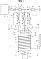
- the temperature controller may include a refrigeration cycle apparatus 13 including a compressor 131, a condenser 132, an expansion device 133, and an evaporator 134, and any one of the condenser 132 and the evaporator 134 may be disposed at the fermentation tank assembly 11.
- the refrigeration cycle apparatus 13 may control a temperature of the fermentation tank 112 by heating the fermentation tank 112.
- the condenser 132 may be disposed in contact with the outer surface of the fermentation tank 112.
- the condenser 132 may include a condensing tube wound around the outer surface of the fermentation tank 112.
- a plurality of different kinds of additives may be separated from one another to be accommodated in the supplier 3.
- the plurality of additives accommodated in the supplier 3 may be yeast, hops, and fragrance additives, and be separated from one another to be accommodated in the supplier 3.
- the supplier 3 may include a first capsule accommodation part 31 in which a first capsule C1 containing the first additive is accommodated, a second capsule accommodation part 32 in which a second capsule C2 containing the second additive is accommodated, and a third capsule accommodation part 33 in which a third capsule C3 containing the third additive is accommodated.
- a first supplier entrance flow path 311 that guides water or air to the first capsule accommodation part 31 may be connected to the first capsule accommodation part 31, and a first supplier exit flow path 312 through which water discharged from the first capsule accommodation part 31, a mixture of the water and the first additive, and air are guided may be connected to the first capsule accommodation part 31.
- a first opening/closing valve 313 that opens/closes the first supplier entrance flow path 311 may be installed in the first supplier entrance flow path 311.
- a first check valve 314 that blocks the fluid of the main flow path 2 from flowing backward to the first capsule accommodation part 31 while allowing a fluid of the first capsule accommodation part 31 to flow in the main flow path 2 may be installed in the first supplier exit flow path 312.
- the fluid may include the water discharged from the first capsule accommodation part 31, the mixture of the water and the first additive, and the air.
- a second supplier entrance flow path 321 that guides water or air to the second capsule accommodation part 32 may be connected to the second capsule accommodation part 32, and a second supplier exit flow path 322 through which water discharged from the second capsule accommodation part 32, a mixture of the water and the second additive, and air are guided may be connected to the second capsule accommodation part 32.
- a second opening/closing valve 323 that opens/closes the second supplier entrance flow path 321 may be installed in the second supplier entrance flow path 321.
- a second check valve 324 that blocks the fluid of the main flow path 2 from flowing backward to the second capsule accommodation part 32 while allowing a fluid of the second capsule accommodation part 32 to flow in the main flow path 2 may be installed in the second supplier exit flow path 322.
- the fluid may include the water discharged from the second capsule accommodation part 32, the mixture of the water and the second additive, and the air.
- a third supplier entrance flow path 331 that guides water or air to the third capsule accommodation part 33 may be connected to the third capsule accommodation part 33, and a third supplier exit flow path through which water discharged from the third capsule accommodation part 33, a mixture of the water and the third additive, and air are guided may be connected to the third capsule accommodation part 33.
- a third opening/closing valve 333 that opens/closes the third supplier entrance flow path 331 may be installed in the third supplier entrance flow path 331.
- a third check valve 334 that blocks the fluid of the main flow path 2 from flowing backward to the third capsule accommodation part 33 while allowing a fluid of the third capsule accommodation part 33 to flow in the main flow path 2 may be installed in the third supplier exit flow path 332.
- the fluid may include the water discharged from the third capsule accommodation part 33, the mixture of the water and the third additive, and the air.
- the beer maker may include a bypass flow path 34 that enables the water supplied from the water flow path 4 to be supplied to the main flow path 2 by bypassing the capsule accommodation parts 31, 32, and 33.
- the bypass flow path 34 may be connected to the water supply flow path 4 and the main flow path 2, and water or air of the water flow path 4 may be guided to the bypass flow path 34 to flow in the main flow path 2 by bypassing the capsule accommodation parts 31, 32, and 33.
- the bypass flow path 34 may be connected in parallel to flow paths of the first capsule accommodation part 31, the second capsule accommodation part 32, and the third capsule accommodation part 33.
- a bypass valve 35 that opens/closes the bypass flow path 34 may be installed in the bypass flow path 34.
- the beer maker may include a main supply flow path that guides the water, the materials of the beer, or the air to the fermentation tank assembly 11 therethrough.
- the main supply flow path may include all of the main flow path 2, the bypass flow path 34, and the water supply flow path 4.
- the main supply flow path may supply all of the water, the air, and the materials of the beer to the fermentation tank assembly 11.
- the beer maker may include the supplier 3, but not the water supply module 5.
- the main supply flow path may include all of the main flow path 2, the bypass flow path 34, and the water supply flow path 4.
- the water supply flow path 4 may be directly connected to a water faucet or include a water supply tube that is connected to the water faucet through a separate connection hose to be supplied with external water.
- the water supply tube may be supplied with external water to supply the external water to the bypass flow path 34 or the supplier 3. That is, the main supply flow path may supply all of the water, the air, and the materials of the beer to the fermentation tank assembly 11 therethrough.
- the beer maker includes the water supply module 5, but may not include the supplier 3.
- the main supply flow path may include the main flow path 2, and the main flow path 2 may be directly connected to the water supply module 5.
- an air injection flow path 81 of an air injector 8 may be connected to the main flow path 2.
- the main supply flow path does not require a separate water supply flow path 4 or bypass flow path 34 that connects the water supply module 5 and the supplier 3, and the main flow path 2 may be directly supplied from the water supply module 5.
- the air injection flow path 81 of the air injector 8 may be connected to a portion located between the water supply module 5 and a main valve 9 in the main flow path 2.
- water of the water supply module 5 may be supplied to the fermentation tank assembly 11 through the main flow path 2
- air of the air injector 8 may be supplied to the fermentation tank assembly 11 through the main flow path 2. That is, the main flow path may supply water and air to the fermentation tank assembly 11.
- the beer maker may not include both of the supplier 3 and the water supply module 5.
- the main supply flow path may include the main flow path 2, and the main flow path 2 may be directly connected to a water faucet or include a water supply tube that is connected to the water faucet through a separate connection hose to be supplied with external water.
- the water supply tube may be supplied with external water to supply the external water to the fermentation tank assembly 11.
- the main flow path 2 may be connected to the first supplier exit flow path 312, the second supplier exit flow path 322, the third supplier exit flow path 332, and the bypass flow path 34.
- the main flow path 2 may include a common tube connected to the fermentation tank assembly 11 and a combination tube connected to the first supplier exit flow path 312, the second supplier exit flow path 322, the third supplier exit flow path 332, the bypass flow path 34 and the common tube.
- the water supply module 5 includes a water tank 51 containing water, a water supply pump 52 that pumps the water of the water tank 51, and the water supply heater 53 that heats the water pumped by the water supply pump 52.
- a water tank outlet flow path 54 may be connected to the water tank 51, and the water supply pump 52 may be connected to the water tank outlet flow path 54.
- a water supply pump outlet flow path 55 may be connected to the water supply pump 52, and the water supply heater 53 may be connected to the water supply pump outlet flow path 55.
- a flow meter 56 that measures a flow rate of the water supply pump outlet flow path 55 may be installed in the water supply pump outlet flow path 55.
- the water supply heater 53 may be a mold heater, and include a heater case through which the water pumped by the water supply pump 52 passes, and a heater installed in the heater case to heat water introduced into the heater case.
- a thermistor 57 that measures a temperature of the water supply heater 53 may be installed in the water supply heater 53.
- a thermal fuse 58 that cuts off current applied to the water supply heater 53 as a circuit is interrupted when the temperature of the water supply heater 53 is high.
- An anti-foaming path 63 may be provided in the beer extraction flow path 61, and foam of the beer flowing from the main flow path 2 to the beer extraction flow path 61 may be minimized by passing through the anti-foaming path 63.
- a mesh, etc., through which foam is filtered, may be provided in the anti-foaming path 63.
- the beer extraction valve 62 may include a lever manipulated by the user and a tap valve having a micro switch that detects a manipulation of the user.
- the beer maker may further include a gas discharger 7 that discharges gas in the fermentation module 1 to the outside.
- the gas discharger 7 may include a gas extraction flow path 71 connected to the fermentation module 1 and a pressure sensor 72 installed in the gas extraction flow path 71.
- the gas discharger 7 may further include a gas opening/closing valve 73 that opens/closes the gas extraction flow path 71.
- the gas discharger 7 may further include an air filter 74 through which gas passing through the gas opening/closing valve 73 passes.
- the gas extraction flow path 71 may be connected to the fermentation tank assembly 11, particularly, the fermentation tank cover 114.
- the gas opening/closing valve 73 may be opened to detect a fermentation degree during a fermentation process.
- the gas in the beer brewing pack 12 may flow in the pressure sensor 72.
- the pressure sensor 72 may sense a pressure of the gas discharged from the beer brewing pack 12.
- the pressure sensor 72, the gas opening/closing valve 73, and the air filter 74 may be sequentially disposed in a gas discharge direction in the gas extraction flow path 71.
- the beer maker may further include the air injector 8 connected to at least one of the main flow path 2 and the water supply flow path 4 to inject air.
- air may be injected into the supplier 3 through the water supply flow path 4.
- the air injected into the water supply flow path 4 may sequentially pass through the supplier 3 and the main flow path 2 and then be injected into the beer brewing pack 12.
- air may be injected into the beer brewing pack 12 through the water supply flow path 4, the bypass flow path 34, and the main flow path 2.
- the air injector 8 may supply the air to materials in the beer brewing pack 12.
- the beer maker may further include the main valve 9 that opens/closes the main flow path 2.
- the main valve 9 may be installed, in the main flow path 2, between a connection part 91 of the main flow path 2 and the beer extraction flow path 61 and a connection part 92 of the main flow path 2 and the fermentation tank assembly 11.
- the main valve 9 may opened when hot water is injected into the beer brewing pack 12, to open the main flow path 2.
- the main valve 9 may be closed while the fermentation tank assembly 11 is cooled, to close the main flow path 2.
- the main valve 9 may be opened when air is injected into the beer brewing pack 12, to open the main flow path 2.
- the main valve 9 may be opened when an additive is supplied to the inside of the beer brewing pack 12, to open the main flow path 2.
- the main valve 9 may be closed while materials are being fermented, to close the inside of the beer brewing pack 12.
- the main valve 9 may be closed when the beer is ripened and kept, to close the inside of the beer brewing pack 12.
- the main valve 9 may be opened when the beer is extracted from the beer extractor 6, to open the main flow path 2.
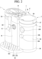
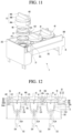
- FIG. 2 is a perspective view of the beer maker according to the embodiment.
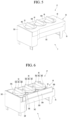
- FIG. 3 is a perspective view illustrating an inside of the beer maker according to the embodiment.
- FIG. 4 is a front view illustrating an inside of the beer maker according to the embodiment.
- the beer maker further includes a base 100.
- the base 100 may form a bottom appearance of the beer maker, and support the fermentation tank assembly 11, the compressor 131, the water supply heater 53, the water supply pump 52, the water tank 51, and the like, which are located at the top side thereof.
- the beer maker may further include a beer container 101 capable of receiving and keeping beer dropping from the beer extraction valve 62.
- the beer container 101 may be integrally formed with the base 100 or be coupled to the base 100.
- Holes 101C through which the beer drops into the container body 101A may be formed in the container top plate 101B.
- the heat insulating wall 102 may be formed of polystyrene foam or the like, which has high heat insulation performance and can absorb vibration.
- the heat insulating wall 102 may be configured as an assembly of a plurality of members.
- the heat insulating wall 102 may include a lower heat insulating wall 102A of which top surface is opened, the lower heat insulating wall 102A having a space formed therein, and an upper heat insulating wall 102B disposed at the top of the lower heat insulating wall 102A, the upper heat insulating wall 102B having the heat insulating wall opening 103 formed in the top surface thereof.
- the heat insulating wall 102 having the lower heat insulating wall 102A and the upper heat insulating wall 102B may surround the circumferential and bottom surfaces of the fermentation tank 112.
- the heat insulating wall opening 103 of the heat insulating wall 102 may surround an upper portion of the fermentation tank 112.
- the heat insulating wall opening 103 of the heat insulating wall 102 may surround the outer surface of a portion at which the heat insulating wall opening 103 is formed in the fermentation tank 112.
- An inner surface 102C of the heat insulating wall 102 may have a larger diameter than an outer surface 112C of the fermentation tank 112, and a gap may be formed between the inner surface 102C of the heat insulating wall 102 and the outer surface 112C of the fermentation tank 112. Air may be filled in the gap, and the air between the inner surface 102C of the heat insulating wall 102 and the outer surface 112C of the fermentation tank 112 may heat-insulate the fermentation tank 112.
- the gap between the inner surface 102C of the heat insulating wall 102 and the outer surface 112C of the fermentation tank 112 may be a space in which the evaporator 134 is accommodated, and simultaneously be a space that can minimize a change in temperature of the fermentation tank 112.
- the fermentation tank 112 may be mounted on a top surface 102E of a bottom plate part 102D of the heat insulating wall 102, and be supported by the top surface 102E of the bottom plate part 102D of the heat insulating wall 102.
- a bottom surface 102F of the bottom plate part 102D of the heat insulating wall 102 may be placed on a heat insulating wall supporter 100A formed on the top surface of the base 100.
- the evaporator 134 may be an evaporating tube wound around the outer surface of the fermentation tank 112 to be located in the gap.
- the evaporator 134 may be in contact with each of the outer surface 112C of the fermentation tank 112 and the inner surface 102C of the heat insulating wall 102.
- the evaporator 134 may be supported by the heat insulating wall 102.
- the beer maker may include a heat insulating wall cover 104 and 105 surrounding the circumferential and top surfaces of the heat insulating wall 102.
- a lower portion of the lower heat insulating wall cover 104 may be placed on the base 100.
- the heat insulating wall cover 104 and 105 may protect the heat insulating wall 102, and form a portion of the appearance of the beer maker.
- the heat insulating wall cover 104 and 105 may surround the entire circumferential surface of the heat insulating wall 102, and surround only a portion of the circumferential surface of the heat insulating wall 102.
- the water tank 51 may be spaced apart from the base 100 at the top side of the base 100.
- the water tank 51 may be spaced apart from the base 100 in the vertical direction.
- a space S3 in which at least one of the compressor 131, the water supply heater 53, and the water supply pump 52 is to be accommodated may be formed between the water tank 51 and the base 100.
- the water tank 51 may be spaced apart from the heat insulating wall 102 in the horizontal direction.
- the beer maker includes a water tank supporter 106 supporting the water tank 51 to be spaced apart from the base 100.
- the water tank supporter 106 is disposed at the base 100, and support the water tank 51 to be spaced apart from the base 100 at the top side of the base 100.
- the bottom end of water tank supporter 106 may be placed on the base 100, and the water tank 51 may be placed at an upper portion of the water tank supporter 106.
- the water tank supporter 106 may be configured such that a plurality of supporter members are entirely coupled in a hollow cylindrical shape. A side opening may be formed in a surface of the water tank supporter 106, which faces the heat insulating wall 102.
- the water tank 51 may include an outer water tank 58, and an inner water tank 59 accommodated in the outer water tank 58, the inner water tank 59 in which a space S4 having water accommodated therein is formed.
- the inner water tank 59 may be inserted into the outer water tank 58, and be supported by the outer water tank 58.
- the beer maker may further include a water tank lid 108 coupled to the water tank 51 or the water tank protector 107 to cover the top surface of the water tank 51.
- a water tank lid 108 coupled to the water tank 51 or the water tank protector 107 to cover the top surface of the water tank 51.
- One side of the water tank lid 108 may be rotatably connected to the water tank 51 or the water tank protector 107.
- the water tank lid 108 may be separably mounted on the top surface of the water tank 51 or the water tank protector 71.
- At least one of the compressor 131, the water supply heater 53, and the water supply pump 52 is disposed between the base 100 and the water tank 51.
- the supplier 3 may be disposed between the fermentation tank cover 114 and the water tank 51.
- the beer maker may be compactly manufactured as compared with when the supplier 3 is located at a position except the space between the fermentation tank cover 114 and the water tank 51, and the supplier 3 may be protected by the fermentation tank cover 114 and the water tank 51.
- one side of the supplier 3 may be mounted on the outer water tank 58, and the other side of the supplier 3 may be mounted on the heat insulating wall cover 104 and 105.
- the supplier 3 may be vertically spaced apart from the base 100 at the top side of the beer maker.
- the supplier 3 may include a capsule accommodation body 36 having the capsule accommodation part in which the capsules C1, C2, and C3 shown in FIG. 1 are attachably/detachably accommodated, and a lid module 37 covering the capsule accommodation part.
- One side plate facing the water tank 51 among left and right side plates of the capsule accommodation body 36 may be mounted on a mounting part formed in the outer water tank 58 to be supported by the outer water tank 58.
- the other side plate facing the fermentation tank cover 114 among the left and right side plates of the capsule accommodation body 36 may be mounted on the heat insulating wall cover 104 and 105, and be supported by the heat insulating wall cover 104 and 105.
- the lid module 37 may include a lid 38 covering the capsule accommodation body 36.
- the lid 38 may be slidingly disposed at the capsule accommodation body 36 or be rotatably connected to the capsule accommodation body 36.
- the lid 38 may be hinge-connected to the capsule accommodation body 36.
- a plurality of parts are preferably accommodated in the accommodation space S5.
- the beer maker may become compact.
- the plurality of parts accommodated in the accommodation space S5 may be protected by being surrounded by the heat insulating wall 102, the water tank 51, the base 100, the supplier 3, the condenser 132, and a center cover 66 which will be described later.
- the opening/closing valves 313, 323, and 333 may be installed in a bracket 64 (see FIG. 3 ) disposed at the base 100.
- the bracket 64 may be disposed to be located at a side of the heat insulating wall 102, and the opening/closing valves 313, 323, and 333 may be installed to be located between the heat insulating wall 102 and the water tank 51 by the bracket 64.
- the opening/closing valves 313, 323, and 333 may be located between the heat insulating wall 102 and the water tank 51 in the left-right direction, and be located between the base 100 and the supplier 3 in the top-bottom direction.
- the center cover 66 may be disposed to cover between the heat insulating wall cover 104 and the water tank supporter 106 in the left-right direction and cover between the supplier 3 and the base 100 in the top-bottom direction.
- the rear surface of the center cover 66 may face the condenser 132 in the front-rear direction, and protect a plurality of parts.
- a front portion of the supplier 3 may be placed on the top end of the center cover 66, and the supplier 3 may be supported by the center cover 66.
- the beer maker may include a controller 109 (see FIG. 3 ) that controls the beer maker.
- the controller 109 may include a wireless communication element that performs wireless communication with a wireless communication device such as a remote controller or a portable terminal.
- the wireless communication element such as a Wi-Fi module or a Bluetooth module, is not limited to its kind as long as it can perform wireless communication with a remote controller or a wireless communication device.
- the wireless communication element may be mounted on the main PCB 109C or a display PCB which will be described later.
- the display 109D may display various information related to brewing of beer while the beer is being brewed.
- the controller 109 may be connected to the temperature sensor 16.
- the controller 109 may transmit information on a temperature sensed by the temperature sensor 16 to the display 109D or the wireless communication device, and the display 109D or the communication device may display the temperature sensed by the temperature sensor 16 through a numerical value, a graph, or the like.
- a first lower through-hole 39A through which a lower portion of a first locker 48 passes may be formed in the lower lid 39
- a second lower through-hole 39B through which a lower portion of a second locker 49 passes may be formed in the lower lid 39
- a third lower through-hole 39C through which a lower portion of a third locker 50 passes may be formed in the lower lid 39.
- the inner water supply flow paths 44, 45, and 46 may communicate with the supplier entrance flow paths 311, 321, and 331, and water passing through the supplier entrance flow paths 311, 321, and 331 may be guided to the inner water supply flow paths 44, 45, and 46 to be introduced into the capsules C1, C2, and C3.
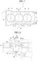
- Each of the water supply bodies 41, 42, and 43 may include a body 41A in which the inner water supply flow path is formed, and a connecting part 41B that guides water to each of the inner water supply flow paths 44, 45, and 46 (see FIG. 8 ).
- each of the water supply bodies 41, 42, and 43 may further include an upper guide part 41C punching the capsule, the upper guide part 41C guiding water of the inner water supply flow path to the inside of the capsule.
- At least one sealing member adhered closely to the top surface of the capsule accommodation body 36 and the bottom surfaces of the water supply bodies 41, 42, and 43 may be disposed between the capsule accommodation body 36 and the water supply bodies 41, 42, and 43.
- a first sealing member 47A disposed between the bottom surface of the first water supply body 41 and the top surface of the capsule accommodation body 36, a second sealing member 47B disposed between the bottom surface of the second water supply body 42 and the top surface of the capsule accommodation body 36, and a third sealing member 47C disposed between the bottom surface of the third water supply body 43 and the top surface of the capsule accommodation body 36 may be disposed between the capsule accommodation body 36 and the lid module 37.
- the first locker 48 may include a water supply body accommodation part that accommodates the first water supply body 41 therein, and the water supply body accommodation part may be disposed to surround the outer circumferential surface and top surface of the first water supply body 41.
- the locker holding part 364 may include a protruding part 364A protruding in the upper direction from the horizontal plate 361 of the capsule accommodation body 36, and a ring part 364B protruding in a ring shape at the upper outer circumference of the protruding part 364A.
- the projection entrance part 365 may be formed to penetrate in the top-bottom direction at a portion of the ring part 364B.
- the projection entrance part 365 may be formed at the ring part 364a to have the same number as the projections 48D.
- a plurality of projection entrance parts 365 may be formed at an equal distance at the ring part 364A.
- the projection 48D may pass through the projection entrance part 365 at the upper side of the projection entrance part 365.
- the projection 48D may be moved downward of the ring part 364B, and be held by the ring part 364B in the upper direction.
- An avoidance hole 482 that avoids the connecting part formed in the water supply body may be formed long in the hollow cylinder 48A.
- the avoidance hole 48E may be formed at a portion of the hollow cylinder 48A, and be formed long in the circumferential direction along the hollow cylinder 48A.
- top surface of the top plate part 48B and the handle part 48C may be exposed to the lid 38, and the user may lock or unlock each of the lockers 48, 49, and 50 to or from the capsule accommodation body 36 by rotating the handle part 48C clockwise or counterclockwise.
- each of lockers 48, 49, and 50 may further include a pressurizing part 48F protruding from the bottom surface of the top plate part 48B to press the water supply body in the direction of the capsule accommodation body.
- the pressurizing part 48F may protrude in the opposite direction of the handle part 48C.
- the pressurizing part 48F may include a convex part 48G convexly formed downward from the bottom surface of the top plate part 48B of each of the lockers 48, 49, and 50, and a pressurizing projection 48H protruding downward at the center of the convex part 48G to press the top surface of the water supply body.
- the pressurizing projection 48H of the pressurizing part 48F may be in contact with the top surface of the water supply body to press the water supply body in the lower direction.
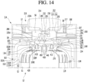
- FIG. 14 is a sectional view illustrating an inside of the fermentation tank assembly of the beer maker according to the embodiment.
- FIG. 15 is a sectional view when the opening shown in FIG. 14 is opened.
- the fermentation tank 112 may include the seat part 116 on which an upper portion of the beer brewing pack 12 is mounted.
- the seat part 116 may include a sealing member supporting bump 117 protruding from the fermentation tank 112 and a fermentation tank sealing member 118 placed on the sealing member supporting bump 117.
- the sealing member supporting bump 117 may protrude in a ring shape in the opening 111.
- the fermentation tank sealing member 118 may be placed on the top surface of the sealing member supporting bump 117.
- a circumferential portion of the beer brewing pack 12 may be placed on the top surface of the fermentation tank sealing member 118, and the inside of the fermentation tank 112 may be sealed by the beer brewing pack 12 and the fermentation sealing member 118.
- An inserting guide 119B into an inserting projection 119A formed at the fermentation tank cover 114 is rotatably inserted may be formed in the opening 111 of the fermentation tank 112.
- the inserting guide 119B may be formed at a portion of the opening 111 of the fermentation tank 112.
- the inserting guide 119B may include a vertical guide groove 119C through which the inserting projection 119A passes approximately in the top-bottom direction, and a horizontal guide groove 119D formed long in the circumferential direction along the opening 111 at a lower portion of the vertical guide groove 119C to guide movement of the inserting projection 119A.
- the inserting projection 119A may be protrude in the horizontal direction at a position capable of facing the opening 111 of the fermentation tank 112 when the fermentation tank cover 114 is closed.
- the inserting guide 119B may be formed in a recessed shape at a higher position than the sealing member supporting bump 117.
- a plurality of ribs 120 that allow a flexible container 420 of the beer brewing pack 12, which will be described later, to be spaced apart from the inner surface of the fermentation tank 112 may protrude from the inner wall of the fermentation tank 112.
- gas may be generated in the beer brewing pack 12, and the flexible container 420 may be expanded by the gas in the beer brewing pack 12.
- air supplied from the beer extraction pressurizing device 15 shown in FIG. 15 may be introduced between the flexible container 420 and the inner surface of the fermentation 112, and the plurality of ribs 120 formed on the inner wall of the fermentation tank 112 may assist smooth flow of the air supplied to the inside of the fermentation tank 112 from the beer extraction pressurizing device 15.
- the plurality of ribs 210 may be formed long in the top-bottom direction.
- the plurality of ribs 120 may be spaced apart from one another in the circumferential direction of the fermentation tank 112 along the inner surface of the fermentation tank 112.
- the plurality of ribs 120 may be formed at each of upper and lower portions of the inner wall of the fermentation tank 112.
- the fermentation cover 114 may include an outer body 200, an inner body 210 rotatably disposed in the outer body 200, and a lower body assembly 240 coupled to a lower portion of the inner body 210, the lower body assembly 240 including a main flow path part 230 to which the main tube 220 is connected.
- An inner space S6 may be formed in at least one of the inner body 210 and the lower body assembly 240.
- at least one portion of the main tube 220 may be accommodated in the inner space S6.
- the main tube 220 may be connected to the main flow path 230 in the inner space S6 of the main tube 220.
- the lower body assembly 240 may include a lower body 250 coupled to the inner body 210, and a flow path body 260 in which the main flow path part 230 is formed.
- the outer body 200 may form an appearance of the circumferential surface of the fermentation tank cover 114.
- the fermentation tank cover 114 may be hinge-connected to the fermentation tank 112 or the heat insulating wall cover 105.
- the outer body 200 may be hinge-connected to the fermentation tank 112 or the heat insulating wall cover 105.
- the outer body 200 may be mounted on the top surface of the heat insulating cover 105.
- the outer body 200 is preferably connected to the heat insulating wall cover 105 by a hinge.
- An inner body accommodation space S7 in which the inner body 210 can be rotatably accommodated may be formed in the outer body 200.
- the outer body 200 may surround the outer circumference of the inner body 210 accommodated in the inner body accommodation space S7, and protect the outer circumference of the inner body 210.
- the inner body 210 may be disposed in the inner body accommodation space S7 to rotate about a vertical center axis.
- the inner body 210 may include an inner frame 212 rotatably disposed in the outer body 200, the inner frame 212 having the inner space S6 formed at a lower portion thereof.
- the inner body 210 may include a handle 214 disposed at the top surface of the inner frame 212. The user may rotate the inner body 210 about the vertical center axis of the inner body 210 while grasping the handle 214. When the inner body 210 is rotated, the lower body assembly 240 may be rotated together with the inner body 210.
- the inner frame 212 may include an inner upper body part 215, an inner lower body part 216 protruding from the bottom surface of the inner upper body part 215, the inner lower body part 216 having the inner space S6 formed therein, and an outer hollow part 217 protruding at the outer circumference of the inner upper body part 216, the outer hollow part 217 being spaced apart from the inner lower body part 216.
- the main flow path part 230 may include an upper flow path part 232 protruding to the inner space S6 at an upper portion of the flow path body 260, and a lower flow path part 234 protruding toward the space S1 of the fermentation tank 112 at a lower portion of the flow path body 260.
- the lower body 250 may be coupled to a lower portion of the inner body 210, and at least one portion of the lower body 250 may be inserted into the opening 111.
- a communication path S9 that guides gas extracted from the beer brewing pack 12 to a sub-flow path part 280 which will be described later may be formed in the lower sealing member 270.
- the lower sealing ember 270 may be a hollow elastic member having the communication path S9 formed therein.
- a portion of the main flow path part 230 may protrude to the communication path S9, and the lower sealing member 270 may protect the main flow path part 230.
- a supply path along which the main tube 220, the main flow path part 230 of the flow path body 260 and the inner hollow part 430 of the beer brewing pack 12 are sequentially continued may be formed in the fermentation tank assembly 11.
- a beer extraction path along which the inner hollow part 430 of the beer brewing pack 12, the main flow path part 230 of the flow path body 260, and the main tube 220 are sequentially continued may be formed in the fermentation tank assembly 11.
- a gas discharge path along which the gas discharge flow path 450 of the beer brewing pack 12, the communication path S9 of the lower sealing member 270, the sub-flow path part 280 of the flow path body 260, and the sub-tube 290 are sequentially continued may be formed in the fermentation tank assembly 11.
- the supply of material, the extraction of beer, and the calculation of a fermentation degree of the beer can be performed in a state in which the fermentation tank cover 114 is not opened but closed.
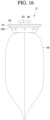
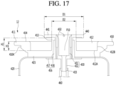
- the beer brewing pack 12 may include a pack body 410 including a mounting part 411 mounted in the fermentation tank assembly 11 shown in FIGS. 14 and 15 , the pack body 410 having an outer hollow part 413 protruding therefrom; the flexible container 420 coupled to the pack body 410; the main flow path body 440 including the inner hollow part 430 inserted and accommodated in the outer hollow part 413, and the main flow path body 440 having a handle part 441 located at the top of the outer hollow part 413; and a flexible tube 460 connected to the inner hollow part 430, the flexible tube 460 protruding to the inside of the flexible container 420.
- the mounting part 411 may be placed and mounted on the seat part 116 shown in FIG. 15 .
- the mounting part 411 may be a part protruding to have a thinner thickness than the other part along an outer circumference 410A of the pack body 410.
- the mounting part 411 may protrude in the radial direction from the pack body 410.
- the mounting part 411 may be formed in a ring shape along the outer circumference 410A of the pack body 410.
- the beer brewing pack 12, as shown in FIG. 14 may be easily mounted in the fermentation tank 112 through a simple operation of inserting the flexible container 420 into the space S1 of the fermentation tank 112 and placing the mounting part 411 on the seat part 116 shown in FIG. 14 .
- a recessed part may be formed at the top surface of the pack body 410.
- the recessed part formed at the top surface of the pack body 410 may be concavely recessed at the top surface of the pack body 410 such that a portion of a finger of the user is easily inserted thereinto.
- the recessed part formed at the top surface of the pack body 410 may be the sealing member mounting groove part 412 shown in FIG. 14 .
- the recessed part may assist the user to easily grasp the handle part 441 of the main flow path body 440 when the beer brewing pack 12 is carried.
- the recessed part When the beer brewing pack 12 is mounted in the fermentation tank 112 as shown in FIG. 14 , the recessed part may be in contact with the lower sealing member 270 of the fermentation tank cover 114.
- the recessed part will be described using the same reference numeral as the sealing member mounting groove part.
- the top surface of the joining part 417 may face the bottom surface of the main body 415.
- the joining part 417 may include a ring-shaped plate body in which the flexible container 420 is joined with the top surface thereof.
- the center hollow part 418 may be located between the inner circumferential surface of the outer hollow part 413 and the outer circumferential surface of the inner hollow part 430.
- the inner hollow part 430 may be separably inserted into the pack body 410.
- the inner hollow part 430 may be inserted into the pack body 410 to be in surface contact with the hollow part 413 and the center hollow part 418.
- the inner hollow part 430 may be inserted into the pack body 410 to be capable of being escaped from the pack body 410 when the user strongly pulls the handle part 441 in the upper direction.
- the main flow path body 440 may be separable from the pack body 410. When a pack main flow path P10 is blocked or when the flexible tube 460 is not normally spread or bent, the main flow path body 440 may be separated from the pack body 410. The user may take an action of replacing the main flow path body 440 or the flexible tube 460.
- At least one gas discharge flow path 450 may be formed in the vicinity of the pack main flow path P10 in the upper hollow part 431.
- a plurality of gas discharge flow paths 450 may be formed in parallel to the pack main flow path P10 between the pack main flow path P10 and the outer circumferential surface of the upper hollow part 431.
- the tube connecting part 432 may include a flexible tube attaching/detaching part 433 to/from which the flexible tube 460 is attached/detached.
- the handle part 441 of the main flow path body 440 may be formed to protrude at an upper portion of the inner hollow part 430.
- the handle part 441 may be formed in a hollow disk shape at the upper portion of the inner hollow part 430.
- the user may carry the beer brewing pack 12 while grasping the mounting part 411 or the handle part 441.
- An outer diameter D1 of the handle part 441 may be greater than that D2 of the outer hollow part 413.
- the bottom surface of the handle part 441 may be placed on the top end of the outer hollow part 413.
- the handle part 412 has a smaller size than the recessed part 412.
- the handle part 441 may be spaced apart from the top surface 414 of the pack body 410 and a circumferential surface 412B of the recessed part 412.
- the user may grasp the handle part 441 of the main flow path body 440 while putting a finger of the user in the recessed part 412, and carry the beer brewing pack 12 to the upper side of the fermentation tank 112 shown in FIG. 15 .
- the user may insert the flexible container 420 into the space S1 of the fermentation tank 112, and place the mounting part 411 on the seat part 116 as shown in FIG. 14 .
- beer brewing pack 12 can be simply mounted in the fermentation tank 112.
- the user may grasp the handle part 441 of the main flow path body 440 with a hand of the user by putting a hand of the user in the opening of the fermentation tank 112, and upwardly lift the beer brewing pack 12.
- the beer brewing pack 12 may be escaped to the upper side of the opening 111 of the fermentation tank 112.
- the beer brewing pack 12 can be easily extracted from the fermentation tank 112.
- the flexible tube 460 may guide water or air guided to the pack main flow path P10 to a deep position in the flexible container 420, and beer contained at a lower portion of the flexible container 420 may easily flow in the pack main flow path P10 through the flexible tube 460.
- the flexible tube 460 may be roundly curved or bent at least once in the flexible container 420.
- the flexible tube 460 may be curved or bent before the beer brewing pack 12 is inserted into the fermentation tank 112.
- the flexible tube 460 may be spread long in the length direction by the air or hot water.
- the flexible tube 460 When the flexible container 420 is maximally expanded, the flexible tube 460 may have a length where the bottom end of the flexible tube 460 is spaced apart from the inner bottom end of the flexible container 420.
- the bottom end of the flexible tube 460 may be sharply formed, and have a shape of which portion is opened in the circumferential direction thereof.
- the flexible tube 460 may have a lower hardness than the main flow path body 440.
- the flexible tube 460 is preferably connected to the tube connecting part 432 of the main flow path body 440 after the flexible tube 460 is manufactured separately from the main flow path body 440.
- the flexible tube 460 may be not connected to the main flow path body 440, but may be a hollow part through which a fluid can pass may integrally protrude long at a lower portion of the main flow path body 440.
- the compactness of the beer brewing pack 12 may not be easily achieved, or it may be inconvenience for the user to grasp the handle part 441 with a hand of the user, depending on the hardness of the main flow path body 440. More specifically, the hardness of the entire main flow path body 440 may be formed low such that the hollow part can be curved or bent. In this case, when the user grasps the handle part 441 of a hand of a user, the handle part 441 may also be curved or bent by the hand of the user. In addition, it may not be easy for the user to grasp the handle part 441 with the hand of the user.
- the hardness of the entire main flow path body 440 including the hollow part may be formed high such that the hardness of the handle part 441 increases.
- the main flow path body 440 may have a structure in which the hollow part is not curved or bent, and the compactness of the beer brewing pack 12 may not be easily performed.
- the flexible tube 460 is preferably connected to the main flow path body 440 after the main flow path body 440 and the flexible tube 460 are manufactured separately from each other.
- the user can easily grasp the handle part having a high hardness with a hand of the user, and the flexible tube 460 having a relatively low hardness can assist the compactness of the beer brewing pack 12 as the hollow part is curved or bent in the flexible tube 460.
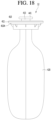
- FIG. 18 is a side view illustrating another example of the beer brewing pack of the beer maker according to the embodiment.
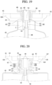
- FIG. 19 is a sectional view illustrating the another example of the beer brewing pack of the beer maker according to the embodiment.
- the connecting body 416" may include a lower hollow part 418" surrounding the outer circumference of the outer hollow part 413".
- the connecting body 416" may further include a joining part 417" protruding at a lower portion of the lower hollow part 418", the joining part 417" having the flexible container 420 joined with at least one of the top and bottom surfaces thereof.
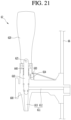
- FIG. 21 is a sectional view illustrating the beer extraction valve of the beer maker according to the embodiment.
- the valve body 600 may be mounted to the center cover 66.
- the valve flow path 611 may include a horizontal flow path 612 formed long in the front-rear direction along the valve body 600, and a vertical flow path 613 formed to be bent in the lower direction at the front end of the horizontal flow path 612. Beer guided to the beer extraction flow path 61 shown in FIG. 1 may sequentially pass through the horizontal flow path 612 and the vertical flow path 613 when the horizontal flow path 612 is opened, and then drop downward from the vertical flow path 613.
- the valve body 600 may include a horizontal part in which the horizontal flow path 612 is formed, and a vertical part formed perpendicular to the horizontal part, the vertical part having the vertical flow path 613 formed therein.
- the lifting valve body 610 may be disposed to move up/down in the valve flow path 611, particularly, the vertical flow path 613.
- the lifting valve body 610 may move down to a height at which the horizontal flow path 612 is blocked, and move up to a height at which the horizontal flow path 612 is opened.
- the lifting valve body 610 may be disposed such that an upper portion of the lifting valve body 610 protrudes upward of the valve body 600.
- a manipulating projection 614 that allows the micro switch 630 to be point-contacted when the lifting valve body 610 moves up may protrude at the lifting valve body 610.
- the rotating lever 620 may be connected to the upper portion of the lifting valve body 610 by a hinge 621.
- the rotating lever 620 may be erected in the vertical direction or laid in the horizontal direction in a state in which the rotating lever 620 is connected to the lifting valve body 610.
- the lifting valve body 610 When the rotating lever 620 is laid in the horizontal direction, the lifting valve body 610 may move up to open the horizontal flow path 612. When the rotating lever 620 is erected in the vertical direction, the lifting valve body 610 may move down to close the horizontal flow path 612.
- the micro switch 630 may be connected to the controller 109 shown in FIG. 3 , and the controller 109 may control the beer maker according to on/off of the micro switch 630.
- the valve spring 640 may be disposed at an upper portion of the vertical part of the valve body 600 to elastically press the lifting valve body 610 in the lower direction.
- FIG. 22 is a flowchart illustrating a control sequence of the beer maker according to the embodiment.
- the beer maker of this embodiment includes the controller 109.
- the user may input an operation command of the beer maker by manipulating a wireless communication device such as the rotary knob 109A, or a remote controller, or a portable terminal.
- the controller 109 may control the beer maker using a preset program according to a switching state of the rotary switch 109B or a signal applied to the wireless communication element.
- the preset program may control the beer maker according to a beer brewing process of the beer maker.
- the beer maker of this embodiment may include a cleansing and sterilizing course for cleansing and sterilizing flow paths in the beer maker.
- the cleansing and sterilizing course may be performed separately from a beer brewing course.
- the cleansing and sterilizing course is preferably performed before the beer brewing course is performed.
- the cleansing and sterilizing course may be performed by a user input during the beer brewing course.
- the cleansing and sterilizing course may be performed in a step in which the main valve 9 is closed and no additive is contained in the supplier 3, such as a primary fermentation step or secondary fermentation step which will be described later.
- the cleansing and sterilizing course may be performed in a state in which the capsules C1, C2, and C3 are not accommodated in the supplier 3, and the beer brewing course may be performed in a state in which the capsules C1, C2, and C3 are accommodated in the supplier 3 and the beer brewing pack 12 is accommodated in the fermentation tank 112.
- the user may input a cleansing and sterilizing command through the input unit, remote controller, or portable terminal provided in the controller 109.
- the controller 109 may control the beer maker in the cleansing and sterilizing course as the cleansing and sterilizing command is input.
- the user may manipulate the beer extraction valve 62 to be opened, and then input the cleansing and sterilizing command through the input unit, remote controller, or portable terminal.
- the controller 109 may turn on the water supply pump 52 and the water supply heater 53 so as to cleanse and sterilize the flow paths, and turn on the bypass valve 35 and the first, second, and third opening/closing valves 313, 323, and 333. In this case, the controller 109 may maintain the main valve 9 to be in a closed state. When the bypass valve 35 and the first, second, and third opening/closing valves 313, 323, and 333 are turned on, the bypass valve 35 and the first, second, and third opening/closing valves 313, 323, and 333 may all be opened.
- water of the water tank 51 may be discharged from the water tank 51 to pass through the water supply pump 52, and flow in the water supply heater 53 to be heated by the water supply heater 53.
- the water (i.e., hot water) heated by the water supply heater 53 may flow in the bypass flow path 34, the first capsule accommodation part 31, the second capsule accommodation part 32, and the third capsule accommodation part 33 through the water supply flow path 4.
- the water flowing in the bypass flow path 34, the first capsule accommodation part 31, the second capsule accommodation part 32, and the third capsule accommodation part 33 may flow in the main flow path 2.
- the water flowing in the main flow path 2 may pass through the beer extraction flow path 61 and then be discharged through the beer extraction valve 62.
- the water supply flow path 4, the bypass flow path 34, the bypass valve 35, the first capsule accommodation part 31, the second capsule accommodation part 32, the third capsule accommodation part 33, the main flow path 2, the beer extraction flow path 61, and the beer extraction valve 62 may be cleansed and sterilized by the hot water heated by the water supply heater 53.
- the above-described cleansing and sterilization may be performed for a cleansing setting time, and the cleansing and sterilizing step (S100) may be completed after the cleansing setting time.
- the controller 109 may turn off the water supply pump 52 and the water supply heater 53, and turn off all of the bypass valve 35 and the first, second, and third opening/closing valves 313, 323, and 333.
- the bypass valve 35 and the first, second, and third opening/closing valves 313, 323, and 333 are turned off, all of the bypass valve 35 and the first, second, and third opening/closing valves 313, 323, and 333 may be closed.
- the user may manipulate the beer extraction valve 62 to be closed such that contamination through the beer extraction valve 62 is blocked in the cleansing and sterilizing step (S100).
- the beer maker of this embodiment may include the beer brewing course for brewing beer.
- the user may mount the beer brewing pack 12 in the fermentation tank 112 by opening the fermentation tank cover 114 and inserting the beer brewing pack 12 into the fermentation tank 112. After that, the user may shut the fermentation tank cover 114, and the beer brewing pack 12 may be accommodated and kept in the fermentation tank 112 and the fermentation tank cover 114.
- the user may insert the plurality of capsules C1, C2, and C3 into the supplier 3 and then cover the plurality of capsule accommodation parts 31, 32, and 33 with the lid module 37 before or after the beer brewing pack 12 is mounted in the fermentation tank 112.
Landscapes
- Chemical & Material Sciences (AREA)
- Organic Chemistry (AREA)
- Engineering & Computer Science (AREA)
- Bioinformatics & Cheminformatics (AREA)
- Life Sciences & Earth Sciences (AREA)
- Biochemistry (AREA)
- Health & Medical Sciences (AREA)
- General Engineering & Computer Science (AREA)
- General Health & Medical Sciences (AREA)
- Genetics & Genomics (AREA)
- Food Science & Technology (AREA)
- Wood Science & Technology (AREA)
- Zoology (AREA)
- Devices For Dispensing Beverages (AREA)
Claims (12)
- Bierherstellungsvorrichtung, die Folgendes umfasst:- eine Fermentationstankanordnung (11), die einen Fermentationstank (112) aufweist, der eine darin ausgebildete Öffnung (111) und eine Fermentationstankabdeckung (114), die die Öffnung (111) öffnet bzw. schließt, aufweist;- eine Kühlkreislaufvorrichtung (13), die Folgendes umfasst:einen Kompressor (131),einen Kondensator (132),eine Expansionsvorrichtung (133) und einen Verdampfer (134), durch die ein Kühlmittel umgewälzt wird, wobei der Verdampfer (134) ein Verdampfungsrohr umfasst, das um eine äußere Oberfläche des Fermentationstanks (112) gewickelt ist,wobei die Kühlkreislaufvorrichtung (13) konfiguriert ist, eine Temperatur des Fermentationstanks (112) zu steuern, wenn der Verdampfer (134) am Fermentationstank (112) angeordnet ist; und- eine Wärmeisolationswand (102), die den Fermentationstank (112) und den Verdampfer (134) zusammen umgibt;dadurch gekennzeichnet, dass die Bierherstellungsvorrichtung ferner Folgendes umfasst:- einen Wassertank (51) zum Enthalten von Wasser;- eine Wasserzufuhrpumpe (52) zum Pumpen von Wasser des Wassertanks (51);- eine Wasserzufuhr-Heizvorrichtung (53) zum Erhitzen des Wassers, das durch die Wasserzufuhrpumpe (52) gepumpt wird; und- eine Zuführvorrichtung (3), die ausgelegt ist, Materialien aufzunehmen, die zum Brauen von Bier erforderlich sind, und die mit der Wasserzufuhr-Heizvorrichtung (53) durch einen Wasserzufuhrströmungspfad (4) verbunden ist, wobei die Zuführvorrichtung (3) durch einen Hauptströmungspfad (2) zum Leiten der Materialien zum Brauen von Bier in die Fermentationstankanordnung (11) mit der Fermentationstankanordnung (11) verbunden ist;- eine Basis (100); und- einen Wassertankträger (106), der an der Basis (100) angeordnet ist, wobei der Wassertankträger (106) den Wassertank (51) so trägt, dass er von der Basis (100) beabstandet ist,wobei der Kompressor (131), die Wasserzufuhr-Heizvorrichtung (53) und/oder die Wasserzufuhrpumpe (52) zwischen der Basis (100) und dem Wassertank (51) angeordnet sind.
- Bierherstellungsvorrichtung nach Anspruch 1, wobei ein Aufnahmeteil (116), an dem eine Bierbraupackung (12) montiert wird, im Fermentationstank (112) ausgebildet ist.
- Bierherstellungsvorrichtung nach Anspruch 1 oder 2, die Folgendes umfasst:eine Luftpumpe (152), die Luft pumpt;einen Luftzufuhrströmungspfad (154), der die Luftpumpe (152) und das Innere der Fermentationstankanordnung (11) verbindet; undein Luftsteuerungsventil, das im Luftzufuhrströmungspfad (154) eingebaut ist.
- Bierherstellungsvorrichtung nach einem der vorhergehenden Ansprüche, wobei der Kondensator (132) so angeordnet ist, dass er zu einem Zwischenraum zwischen der Wärmeisolationswand (102) und dem Wassertank (51) und/oder zur Wärmeisolationswand (102) zeigt.
- Bierherstellungsvorrichtung nach einem der vorhergehenden Ansprüche, wobei der Wassertank (51) von der Wärmeisolationswand (102) in horizontaler Richtung beabstandet ist.
- Bierherstellungsvorrichtung nach einem der vorhergehenden Ansprüche, wobei die Zuführvorrichtung (3) zwischen der Fermentationstankabdeckung und dem Wassertank (51) angeordnet ist.
- Bierherstellungsvorrichtung nach einem der vorhergehenden Ansprüche, die ferner Folgendes umfasst:einen Strömungspfad (81) zum Einblasen von Luft, der mit dem Wasserzufuhrströmungspfad (4) und/oder dem Hauptströmungspfad (2) verbunden ist; undeine Lufteinblaspumpe (82), die Luft in den einen Strömungspfad (81) zum Einblasen von Luft pumpt.
- Bierherstellungsvorrichtung nach einem der vorhergehenden Ansprüche, die ferner Folgendes umfasst:einen Bierextraktionsströmungspfad (61), der mit dem Hauptströmungspfad (2) verbunden ist; undein Bierextraktionsventil (62), das mit dem Bierextraktionsströmungspfad (61) verbunden ist.
- Bierherstellungsvorrichtung nach einem der vorhergehenden Ansprüche, die ferner ein Hauptventil (9) umfasst, das im Hauptströmungspfad (2) eingebaut ist,
wobei das Hauptventil (9) zwischen einem Verbindungsteil des Hauptströmungspfads (2) mit dem Bierextraktionsströmungspfad (61) und einem Verbindungsteil des Hauptströmungspfads (2) mit der Fermentationstankanordnung (11) eingebaut ist. - Bierherstellungsvorrichtung nach einem der Ansprüche 1 bis 9, die ferner Folgendes umfasst:einen Gasextraktionsströmungspfad (71), der mit der Fermentationstankabdeckung verbunden ist;einen Drucksensor, der im Gasextraktionsströmungspfad (71) eingebaut ist; undein Gasventil zum Öffnen bzw. Schließen, das den Gasextraktionsströmungspfad (71) öffnet bzw. schließt.
- Bierherstellungsvorrichtung nach einem der Ansprüche 1 bis 10, wobei die Wärmeisolationswand (102) Folgendes umfasst:eine untere Wärmeisolationswand (102A), die eine offene obere Oberfläche aufweist, wobei die untere Wärmeisolationswand (102A) einen darin ausgebildeten Raum aufweist; undeine obere Wärmeisolationswand (102B), die an der Oberseite der unteren Wärmeisolationswand (102A) angeordnet ist, wobei die obere Wärmeisolationswand (102B) eine offene Oberfläche aufweist, in der eine Öffnung der Wärmeisolationswand, die einen oberen Abschnitt des Fermentationstanks (112) umgibt, ausgebildet ist.
- Bierherstellungsvorrichtung nach einem der Ansprüche 1 bis 11, die ferner eine Wärmeisolationswand-Abdeckung (104, 105) umfasst, die die Umfangsfläche und die obere Oberfläche der Wärmeisolationswand (102) umgibt,
wobei ein oberes Durchgangsloch an einem oberen Abschnitt der Wärmeisolationswand-Abdeckung (104, 105) ausgebildet ist.
Applications Claiming Priority (10)
| Application Number | Priority Date | Filing Date | Title |
|---|---|---|---|
| US201662338498P | 2016-05-18 | 2016-05-18 | |
| KR1020160105790A KR102118683B1 (ko) | 2016-05-18 | 2016-08-19 | 발효장치 |
| KR1020160105788A KR102108424B1 (ko) | 2016-05-18 | 2016-08-19 | 발효장치 |
| KR1020160105791A KR102108427B1 (ko) | 2016-05-18 | 2016-08-19 | 맥주 제조장치 |
| KR1020160105794A KR102111150B1 (ko) | 2016-05-18 | 2016-08-19 | 발효장치 |
| KR1020160105789A KR102118082B1 (ko) | 2016-05-18 | 2016-08-19 | 발효 장치 |
| KR1020160105792A KR102048424B1 (ko) | 2016-05-18 | 2016-08-19 | 발효장치 |
| KR1020160105796A KR102092958B1 (ko) | 2016-05-18 | 2016-08-19 | 맥주 제조팩 및 그를 갖는 맥주 제조장치 |
| KR1020160105793A KR102118089B1 (ko) | 2016-05-18 | 2016-08-19 | 맥주 제조장치 |
| KR1020160166574A KR102124460B1 (ko) | 2016-12-08 | 2016-12-08 | 발효장치 및 그 운전 방법 |
Publications (2)
| Publication Number | Publication Date |
|---|---|
| EP3246385A1 EP3246385A1 (de) | 2017-11-22 |
| EP3246385B1 true EP3246385B1 (de) | 2025-07-02 |
Family
ID=60080555
Family Applications (8)
| Application Number | Title | Priority Date | Filing Date |
|---|---|---|---|
| EP17171788.7A Active EP3246386B1 (de) | 2016-05-18 | 2017-05-18 | Bierzubereiter |
| EP17171819.0A Active EP3246391B1 (de) | 2016-05-18 | 2017-05-18 | Bierzubereiter |
| EP17171825.7A Active EP3246392B1 (de) | 2016-05-18 | 2017-05-18 | Bierzubereiter |
| EP17171727.5A Active EP3246385B1 (de) | 2016-05-18 | 2017-05-18 | Bierzubereiter |
| EP17171816.6A Active EP3246390B1 (de) | 2016-05-18 | 2017-05-18 | Bierzubereiter |
| EP17171808.3A Active EP3246389B1 (de) | 2016-05-18 | 2017-05-18 | Bierzubereiter |
| EP17171797.8A Active EP3246388B1 (de) | 2016-05-18 | 2017-05-18 | Bierzubereiter |
| EP17171791.1A Active EP3246387B1 (de) | 2016-05-18 | 2017-05-18 | Bierzubereiter |
Family Applications Before (3)
| Application Number | Title | Priority Date | Filing Date |
|---|---|---|---|
| EP17171788.7A Active EP3246386B1 (de) | 2016-05-18 | 2017-05-18 | Bierzubereiter |
| EP17171819.0A Active EP3246391B1 (de) | 2016-05-18 | 2017-05-18 | Bierzubereiter |
| EP17171825.7A Active EP3246392B1 (de) | 2016-05-18 | 2017-05-18 | Bierzubereiter |
Family Applications After (4)
| Application Number | Title | Priority Date | Filing Date |
|---|---|---|---|
| EP17171816.6A Active EP3246390B1 (de) | 2016-05-18 | 2017-05-18 | Bierzubereiter |
| EP17171808.3A Active EP3246389B1 (de) | 2016-05-18 | 2017-05-18 | Bierzubereiter |
| EP17171797.8A Active EP3246388B1 (de) | 2016-05-18 | 2017-05-18 | Bierzubereiter |
| EP17171791.1A Active EP3246387B1 (de) | 2016-05-18 | 2017-05-18 | Bierzubereiter |
Country Status (1)
| Country | Link |
|---|---|
| EP (8) | EP3246386B1 (de) |
Families Citing this family (8)
| Publication number | Priority date | Publication date | Assignee | Title |
|---|---|---|---|---|
| KR102282446B1 (ko) | 2017-05-25 | 2021-07-28 | 엘지전자 주식회사 | 음료 제조기 |
| KR102548266B1 (ko) | 2017-11-15 | 2023-06-27 | 엘지전자 주식회사 | 발효조 |
| KR102708122B1 (ko) * | 2018-11-27 | 2024-09-24 | 엘지전자 주식회사 | 음료 제조기 및 그의 제어 방법 |
| KR102282483B1 (ko) * | 2019-05-13 | 2021-07-28 | 엘지전자 주식회사 | 발효 및 숙성 장치 |
| KR102274525B1 (ko) * | 2019-05-14 | 2021-07-08 | 엘지전자 주식회사 | 발효 및 숙성 장치 및 그의 제어 방법 |
| CN111762745A (zh) * | 2020-06-19 | 2020-10-13 | 武汉盛硕电子有限公司 | 一种饮品分离器和饮品控制的方法 |
| ES3009504T3 (en) | 2022-02-25 | 2025-03-27 | Carlsberg Breweries As | Cooling arrangement for a beverage dispensing system |
| CN118256334B (zh) * | 2024-05-30 | 2025-06-24 | 山东中创健康科技集团有限公司 | 微生物添加剂发酵空气多级过滤除菌装置 |
Citations (3)
| Publication number | Priority date | Publication date | Assignee | Title |
|---|---|---|---|---|
| GB2335902A (en) * | 1998-04-01 | 1999-10-06 | Miracle Beer Company Limited | Micro-brewing device |
| CN2510497Y (zh) * | 2001-11-04 | 2002-09-11 | 刘锦明 | 一种啤酒酿酒设备 |
| EP3406699A1 (de) * | 2016-01-19 | 2018-11-28 | LG Electronics Inc. -1- | Vorrichtung zur herstellung von bier |
Family Cites Families (22)
| Publication number | Priority date | Publication date | Assignee | Title |
|---|---|---|---|---|
| GB274225A (en) * | 1926-04-26 | 1927-07-21 | Hansena A G | An improved method of fermenting and maturing beer and apparatus therefor |
| GB2077759B (en) * | 1980-05-23 | 1984-02-01 | Ward John Robert Jnr | Brewing alcoholic beverages and apparatus therefor |
| US4754698A (en) * | 1986-12-01 | 1988-07-05 | Naish Ralph P | Home brewing apparatus |
| AU634245B2 (en) * | 1989-06-28 | 1993-02-18 | Monterrey Pty Ltd | Fermenting apparatus |
| JPH07327658A (ja) * | 1994-04-14 | 1995-12-19 | Nippon Kiden Kk | ビール醸造器 |
| US5718161A (en) * | 1996-05-20 | 1998-02-17 | Beadle; Leigh P. | Beer brewing system and method |
| WO1998050521A1 (en) * | 1997-05-06 | 1998-11-12 | Product Design Group, Inc. | Automated home beer brewing machine and method |
| KR200319526Y1 (ko) | 2003-04-02 | 2003-07-12 | 김은미 | 가정용 맥주 제조기구 |
| US20070266713A1 (en) * | 2005-01-19 | 2007-11-22 | Fifth Ocean Engineering Limited | Unit for After Fermentation and/or Storing, and/or Transportation, and/or Dispense of Beer |
| EP1961804A1 (de) * | 2006-12-15 | 2008-08-27 | 4384814 Canada Inc. | Weinvergärungsbehälter mit Behältervorrichtung für die Maische |
| ES2661176T3 (es) * | 2007-08-01 | 2018-03-27 | Williamswarn Holdings Limited | Sistema de elaboración combinada |
| US8141477B2 (en) * | 2008-05-13 | 2012-03-27 | William Broderick | Mash/lauter tun and method of use thereof |
| KR200457639Y1 (ko) | 2010-06-08 | 2011-12-28 | 김수갑 | 생맥주 냉각구조 |
| US20140017354A1 (en) * | 2012-07-05 | 2014-01-16 | James Joseph | Beer brewing system and method |
| US9546348B2 (en) * | 2012-11-28 | 2017-01-17 | Demon Brewing Company, Inc. | Conical brewing device with nesting supporting member |
| WO2014209138A1 (en) * | 2013-06-28 | 2014-12-31 | Watsonbrew Ip Limited | A beverage apparatus and method |
| EP2856917A1 (de) * | 2013-10-01 | 2015-04-08 | Luna Technology Systems LTS GmbH | Brühmodul |
| KR101668155B1 (ko) | 2014-08-08 | 2016-10-20 | 김선철 | 발효액 제조장치 및 발효액 제조방법 |
| EP3000777A1 (de) * | 2014-09-26 | 2016-03-30 | Anheuser-Busch InBev S.A. | Getränkeausgabevorrichtung mit Mischkammer und Kühlfunktionalität |
| EP3000778A1 (de) * | 2014-09-26 | 2016-03-30 | Anheuser-Busch InBev S.A. | Getränkespender mit Strahlmischeinrichtung |
| AT516563B1 (de) * | 2014-11-28 | 2016-11-15 | Moser Gilbert | Kleinbrauanlage |
| KR102582524B1 (ko) * | 2016-01-19 | 2023-09-26 | 엘지전자 주식회사 | 발효 및 디스펜스 장치 |
-
2017
- 2017-05-18 EP EP17171788.7A patent/EP3246386B1/de active Active
- 2017-05-18 EP EP17171819.0A patent/EP3246391B1/de active Active
- 2017-05-18 EP EP17171825.7A patent/EP3246392B1/de active Active
- 2017-05-18 EP EP17171727.5A patent/EP3246385B1/de active Active
- 2017-05-18 EP EP17171816.6A patent/EP3246390B1/de active Active
- 2017-05-18 EP EP17171808.3A patent/EP3246389B1/de active Active
- 2017-05-18 EP EP17171797.8A patent/EP3246388B1/de active Active
- 2017-05-18 EP EP17171791.1A patent/EP3246387B1/de active Active
Patent Citations (3)
| Publication number | Priority date | Publication date | Assignee | Title |
|---|---|---|---|---|
| GB2335902A (en) * | 1998-04-01 | 1999-10-06 | Miracle Beer Company Limited | Micro-brewing device |
| CN2510497Y (zh) * | 2001-11-04 | 2002-09-11 | 刘锦明 | 一种啤酒酿酒设备 |
| EP3406699A1 (de) * | 2016-01-19 | 2018-11-28 | LG Electronics Inc. -1- | Vorrichtung zur herstellung von bier |
Non-Patent Citations (1)
| Title |
|---|
| BREWING B D E: "Brewing: Science and practice", BREWING SCIENCE AND PRACTICE, WOODHEAD PUBLISHING, CAMBRIDGE, GB, 1 January 2004 (2004-01-01), pages 513 - 527, 655, XP003018692 * |
Also Published As
| Publication number | Publication date |
|---|---|
| EP3246385A1 (de) | 2017-11-22 |
| EP3246392B1 (de) | 2024-03-27 |
| EP3246391A1 (de) | 2017-11-22 |
| EP3246390A1 (de) | 2017-11-22 |
| EP3246390B1 (de) | 2024-03-20 |
| EP3246392A1 (de) | 2017-11-22 |
| EP3246386B1 (de) | 2024-03-20 |
| EP3246389A1 (de) | 2017-11-22 |
| EP3246386A1 (de) | 2017-11-22 |
| EP3246391B1 (de) | 2021-11-10 |
| EP3246388A1 (de) | 2017-11-22 |
| EP3246387B1 (de) | 2024-04-10 |
| EP3246387A1 (de) | 2017-11-22 |
| EP3246389B1 (de) | 2024-07-03 |
| EP3246388B1 (de) | 2024-09-04 |
Similar Documents
| Publication | Publication Date | Title |
|---|---|---|
| KR102431665B1 (ko) | 음료 제조장치 | |
| EP3246385B1 (de) | Bierzubereiter | |
| US11767210B2 (en) | Beverage making apparatus | |
| CN107400588B (zh) | 啤酒酿造装置 | |
| US11453547B2 (en) | Beverage ingredient pack and beverage making apparatus having the same | |
| CN107400582B (zh) | 啤酒酿造装置 | |
| US11168290B2 (en) | Beverage making apparatus | |
| CN107400584B (zh) | 啤酒酿造装置 | |
| US11268055B2 (en) | Beverage making apparatus | |
| US11154159B2 (en) | Beverage-making apparatus | |
| KR20190029300A (ko) | 음료 제조기 | |
| CN113549508A (zh) | 啤酒酿造装置 | |
| KR20190032117A (ko) | 음료 제조기 |
Legal Events
| Date | Code | Title | Description |
|---|---|---|---|
| PUAI | Public reference made under article 153(3) epc to a published international application that has entered the european phase |
Free format text: ORIGINAL CODE: 0009012 |
|
| STAA | Information on the status of an ep patent application or granted ep patent |
Free format text: STATUS: THE APPLICATION HAS BEEN PUBLISHED |
|
| AK | Designated contracting states |
Kind code of ref document: A1 Designated state(s): AL AT BE BG CH CY CZ DE DK EE ES FI FR GB GR HR HU IE IS IT LI LT LU LV MC MK MT NL NO PL PT RO RS SE SI SK SM TR |
|
| AX | Request for extension of the european patent |
Extension state: BA ME |
|
| STAA | Information on the status of an ep patent application or granted ep patent |
Free format text: STATUS: REQUEST FOR EXAMINATION WAS MADE |
|
| 17P | Request for examination filed |
Effective date: 20180418 |
|
| RBV | Designated contracting states (corrected) |
Designated state(s): AL AT BE BG CH CY CZ DE DK EE ES FI FR GB GR HR HU IE IS IT LI LT LU LV MC MK MT NL NO PL PT RO RS SE SI SK SM TR |
|
| STAA | Information on the status of an ep patent application or granted ep patent |
Free format text: STATUS: EXAMINATION IS IN PROGRESS |
|
| 17Q | First examination report despatched |
Effective date: 20210514 |
|
| REG | Reference to a national code |
Ref legal event code: R079 Ref country code: DE Ref document number: 602017090236 Country of ref document: DE Free format text: PREVIOUS MAIN CLASS: C12C0013100000 Ipc: C12C0011000000 |
|
| RIC1 | Information provided on ipc code assigned before grant |
Ipc: C12C 13/10 20060101ALI20241126BHEP Ipc: C12C 13/02 20060101ALI20241126BHEP Ipc: C12C 11/00 20060101AFI20241126BHEP |
|
| GRAP | Despatch of communication of intention to grant a patent |
Free format text: ORIGINAL CODE: EPIDOSNIGR1 |
|
| STAA | Information on the status of an ep patent application or granted ep patent |
Free format text: STATUS: GRANT OF PATENT IS INTENDED |
|
| INTG | Intention to grant announced |
Effective date: 20250116 |
|
| GRAS | Grant fee paid |
Free format text: ORIGINAL CODE: EPIDOSNIGR3 |
|
| GRAA | (expected) grant |
Free format text: ORIGINAL CODE: 0009210 |
|
| STAA | Information on the status of an ep patent application or granted ep patent |
Free format text: STATUS: THE PATENT HAS BEEN GRANTED |
|
| AK | Designated contracting states |
Kind code of ref document: B1 Designated state(s): AL AT BE BG CH CY CZ DE DK EE ES FI FR GB GR HR HU IE IS IT LI LT LU LV MC MK MT NL NO PL PT RO RS SE SI SK SM TR |
|
| REG | Reference to a national code |
Ref country code: GB Ref legal event code: FG4D |
|
| REG | Reference to a national code |
Ref country code: CH Ref legal event code: EP |
|
| REG | Reference to a national code |
Ref country code: DE Ref legal event code: R096 Ref document number: 602017090236 Country of ref document: DE |
|
| REG | Reference to a national code |
Ref country code: IE Ref legal event code: FG4D |
|
| REG | Reference to a national code |
Ref country code: NL Ref legal event code: MP Effective date: 20250702 |
|
| PG25 | Lapsed in a contracting state [announced via postgrant information from national office to epo] |
Ref country code: PT Free format text: LAPSE BECAUSE OF FAILURE TO SUBMIT A TRANSLATION OF THE DESCRIPTION OR TO PAY THE FEE WITHIN THE PRESCRIBED TIME-LIMIT Effective date: 20251103 |
|
| PG25 | Lapsed in a contracting state [announced via postgrant information from national office to epo] |
Ref country code: NL Free format text: LAPSE BECAUSE OF FAILURE TO SUBMIT A TRANSLATION OF THE DESCRIPTION OR TO PAY THE FEE WITHIN THE PRESCRIBED TIME-LIMIT Effective date: 20250702 |
|
| REG | Reference to a national code |
Ref country code: AT Ref legal event code: MK05 Ref document number: 1809290 Country of ref document: AT Kind code of ref document: T Effective date: 20250702 |
|
| PG25 | Lapsed in a contracting state [announced via postgrant information from national office to epo] |
Ref country code: IS Free format text: LAPSE BECAUSE OF FAILURE TO SUBMIT A TRANSLATION OF THE DESCRIPTION OR TO PAY THE FEE WITHIN THE PRESCRIBED TIME-LIMIT Effective date: 20251102 |
|
| PG25 | Lapsed in a contracting state [announced via postgrant information from national office to epo] |
Ref country code: NO Free format text: LAPSE BECAUSE OF FAILURE TO SUBMIT A TRANSLATION OF THE DESCRIPTION OR TO PAY THE FEE WITHIN THE PRESCRIBED TIME-LIMIT Effective date: 20251002 |
|
| REG | Reference to a national code |
Ref country code: LT Ref legal event code: MG9D |
|
| PG25 | Lapsed in a contracting state [announced via postgrant information from national office to epo] |
Ref country code: AT Free format text: LAPSE BECAUSE OF FAILURE TO SUBMIT A TRANSLATION OF THE DESCRIPTION OR TO PAY THE FEE WITHIN THE PRESCRIBED TIME-LIMIT Effective date: 20250702 |
|
| PG25 | Lapsed in a contracting state [announced via postgrant information from national office to epo] |
Ref country code: FI Free format text: LAPSE BECAUSE OF FAILURE TO SUBMIT A TRANSLATION OF THE DESCRIPTION OR TO PAY THE FEE WITHIN THE PRESCRIBED TIME-LIMIT Effective date: 20250702 |
|
| PG25 | Lapsed in a contracting state [announced via postgrant information from national office to epo] |
Ref country code: HR Free format text: LAPSE BECAUSE OF FAILURE TO SUBMIT A TRANSLATION OF THE DESCRIPTION OR TO PAY THE FEE WITHIN THE PRESCRIBED TIME-LIMIT Effective date: 20250702 |
|
| PG25 | Lapsed in a contracting state [announced via postgrant information from national office to epo] |
Ref country code: GR Free format text: LAPSE BECAUSE OF FAILURE TO SUBMIT A TRANSLATION OF THE DESCRIPTION OR TO PAY THE FEE WITHIN THE PRESCRIBED TIME-LIMIT Effective date: 20251003 |
|
| PG25 | Lapsed in a contracting state [announced via postgrant information from national office to epo] |
Ref country code: CZ Free format text: LAPSE BECAUSE OF FAILURE TO SUBMIT A TRANSLATION OF THE DESCRIPTION OR TO PAY THE FEE WITHIN THE PRESCRIBED TIME-LIMIT Effective date: 20250702 Ref country code: SE Free format text: LAPSE BECAUSE OF FAILURE TO SUBMIT A TRANSLATION OF THE DESCRIPTION OR TO PAY THE FEE WITHIN THE PRESCRIBED TIME-LIMIT Effective date: 20250702 |
|
| PG25 | Lapsed in a contracting state [announced via postgrant information from national office to epo] |
Ref country code: LV Free format text: LAPSE BECAUSE OF FAILURE TO SUBMIT A TRANSLATION OF THE DESCRIPTION OR TO PAY THE FEE WITHIN THE PRESCRIBED TIME-LIMIT Effective date: 20250702 |
|
| PG25 | Lapsed in a contracting state [announced via postgrant information from national office to epo] |
Ref country code: PL Free format text: LAPSE BECAUSE OF FAILURE TO SUBMIT A TRANSLATION OF THE DESCRIPTION OR TO PAY THE FEE WITHIN THE PRESCRIBED TIME-LIMIT Effective date: 20250702 Ref country code: BG Free format text: LAPSE BECAUSE OF FAILURE TO SUBMIT A TRANSLATION OF THE DESCRIPTION OR TO PAY THE FEE WITHIN THE PRESCRIBED TIME-LIMIT Effective date: 20250702 |
|
| PG25 | Lapsed in a contracting state [announced via postgrant information from national office to epo] |
Ref country code: RS Free format text: LAPSE BECAUSE OF FAILURE TO SUBMIT A TRANSLATION OF THE DESCRIPTION OR TO PAY THE FEE WITHIN THE PRESCRIBED TIME-LIMIT Effective date: 20251002 |
|
| PG25 | Lapsed in a contracting state [announced via postgrant information from national office to epo] |
Ref country code: ES Free format text: LAPSE BECAUSE OF FAILURE TO SUBMIT A TRANSLATION OF THE DESCRIPTION OR TO PAY THE FEE WITHIN THE PRESCRIBED TIME-LIMIT Effective date: 20250702 |
|
| PG25 | Lapsed in a contracting state [announced via postgrant information from national office to epo] |
Ref country code: SM Free format text: LAPSE BECAUSE OF FAILURE TO SUBMIT A TRANSLATION OF THE DESCRIPTION OR TO PAY THE FEE WITHIN THE PRESCRIBED TIME-LIMIT Effective date: 20250702 |
|
| PG25 | Lapsed in a contracting state [announced via postgrant information from national office to epo] |
Ref country code: DK Free format text: LAPSE BECAUSE OF FAILURE TO SUBMIT A TRANSLATION OF THE DESCRIPTION OR TO PAY THE FEE WITHIN THE PRESCRIBED TIME-LIMIT Effective date: 20250702 |
|
| PG25 | Lapsed in a contracting state [announced via postgrant information from national office to epo] |
Ref country code: IT Free format text: LAPSE BECAUSE OF FAILURE TO SUBMIT A TRANSLATION OF THE DESCRIPTION OR TO PAY THE FEE WITHIN THE PRESCRIBED TIME-LIMIT Effective date: 20250702 |
|
| PG25 | Lapsed in a contracting state [announced via postgrant information from national office to epo] |
Ref country code: SK Free format text: LAPSE BECAUSE OF FAILURE TO SUBMIT A TRANSLATION OF THE DESCRIPTION OR TO PAY THE FEE WITHIN THE PRESCRIBED TIME-LIMIT Effective date: 20250702 Ref country code: EE Free format text: LAPSE BECAUSE OF FAILURE TO SUBMIT A TRANSLATION OF THE DESCRIPTION OR TO PAY THE FEE WITHIN THE PRESCRIBED TIME-LIMIT Effective date: 20250702 |