EP3246471B1 - Dispositif et procédé de connexion d'une structure tubulaire creuse dans un état déployé à un travail d'un dispositif flottant - Google Patents
Dispositif et procédé de connexion d'une structure tubulaire creuse dans un état déployé à un travail d'un dispositif flottant Download PDFInfo
- Publication number
- EP3246471B1 EP3246471B1 EP17171379.5A EP17171379A EP3246471B1 EP 3246471 B1 EP3246471 B1 EP 3246471B1 EP 17171379 A EP17171379 A EP 17171379A EP 3246471 B1 EP3246471 B1 EP 3246471B1
- Authority
- EP
- European Patent Office
- Prior art keywords
- clamping
- tubular structure
- hollow tubular
- work deck
- clamping parts
- Prior art date
- Legal status (The legal status is an assumption and is not a legal conclusion. Google has not performed a legal analysis and makes no representation as to the accuracy of the status listed.)
- Active
Links
Images



Classifications
-
- E—FIXED CONSTRUCTIONS
- E02—HYDRAULIC ENGINEERING; FOUNDATIONS; SOIL SHIFTING
- E02D—FOUNDATIONS; EXCAVATIONS; EMBANKMENTS; UNDERGROUND OR UNDERWATER STRUCTURES
- E02D27/00—Foundations as substructures
- E02D27/32—Foundations for special purposes
- E02D27/42—Foundations for poles, masts or chimneys
- E02D27/425—Foundations for poles, masts or chimneys specially adapted for wind motors masts
-
- B—PERFORMING OPERATIONS; TRANSPORTING
- B63—SHIPS OR OTHER WATERBORNE VESSELS; RELATED EQUIPMENT
- B63B—SHIPS OR OTHER WATERBORNE VESSELS; EQUIPMENT FOR SHIPPING
- B63B21/00—Tying-up; Shifting, towing, or pushing equipment; Anchoring
- B63B21/24—Anchors
- B63B21/26—Anchors securing to bed
- B63B21/27—Anchors securing to bed by suction
-
- E—FIXED CONSTRUCTIONS
- E02—HYDRAULIC ENGINEERING; FOUNDATIONS; SOIL SHIFTING
- E02D—FOUNDATIONS; EXCAVATIONS; EMBANKMENTS; UNDERGROUND OR UNDERWATER STRUCTURES
- E02D25/00—Joining caissons, sinkers, or other units to each other under water
-
- E—FIXED CONSTRUCTIONS
- E02—HYDRAULIC ENGINEERING; FOUNDATIONS; SOIL SHIFTING
- E02B—HYDRAULIC ENGINEERING
- E02B17/00—Artificial islands mounted on piles or like supports, e.g. platforms on raisable legs or offshore constructions; Construction methods therefor
- E02B2017/0056—Platforms with supporting legs
- E02B2017/0073—Details of sea bottom engaging footing
- E02B2017/0078—Suction piles, suction cans
-
- E—FIXED CONSTRUCTIONS
- E02—HYDRAULIC ENGINEERING; FOUNDATIONS; SOIL SHIFTING
- E02B—HYDRAULIC ENGINEERING
- E02B17/00—Artificial islands mounted on piles or like supports, e.g. platforms on raisable legs or offshore constructions; Construction methods therefor
- E02B2017/0091—Offshore structures for wind turbines
-
- Y—GENERAL TAGGING OF NEW TECHNOLOGICAL DEVELOPMENTS; GENERAL TAGGING OF CROSS-SECTIONAL TECHNOLOGIES SPANNING OVER SEVERAL SECTIONS OF THE IPC; TECHNICAL SUBJECTS COVERED BY FORMER USPC CROSS-REFERENCE ART COLLECTIONS [XRACs] AND DIGESTS
- Y02—TECHNOLOGIES OR APPLICATIONS FOR MITIGATION OR ADAPTATION AGAINST CLIMATE CHANGE
- Y02E—REDUCTION OF GREENHOUSE GAS [GHG] EMISSIONS, RELATED TO ENERGY GENERATION, TRANSMISSION OR DISTRIBUTION
- Y02E10/00—Energy generation through renewable energy sources
- Y02E10/70—Wind energy
- Y02E10/727—Offshore wind turbines
Definitions
- the invention relates to an assembly and to method for connecting a hollow tubular structure in erected state to a work deck of a floating device.
- the invention will be elucidated hereinbelow in the light of the offshore placing of a wind turbine.
- the reference to a wind turbine does not imply that the invention is limited to the use in the context of such a wind turbine.
- the device and method can in principle be applied to any hollow tubular structure which has to be transported over sea in erected state.
- An offshore wind turbine is generally placed on a support structure which is anchored to the seabed in any way.
- the support structure is configured to bridge the distance from the seabed to a position above the water surface and can be embodied in different ways.
- the support structure can thus comprise a single pile (a monopile) or be embodied as a lattice structure, also referred to as jacket.
- the support structure has to be anchored to the bottom in any way, wherein a pile foundation is common.
- the foundation piles are connected to the support structure on an underside of the support structure, for instance by means of a grouted connection.
- suction buckets are arranged on an underside of the legs of a jacket, wherein the bucket openings are directed toward the seabed.
- Suction buckets are hollow tubular structures which can have sizable dimensions, with diameters of as much as 10 m and more.
- the wall thickness of the suction buckets is however limited in proportion to the diameter and height thereof, for instance in the range of only tens of mm.
- the limited wall thickness makes the suction buckets susceptible to buckling, particularly when the suction buckets are loaded out of the plane of their wall.
- Hollow tubular structures with a certain length are generally transported over sea in erected state.
- a jacket of a wind turbine provided with suction buckets is lifted onto the deck of a transport vessel and fixed onto the work deck of the vessel by welding lower peripheral edges of the suction buckets to the work deck. After arrival at the intended offshore location, the welds are broken and the jacket provided with suction buckets can be taken up and placed on the seabed.
- the known method has the drawback, among others, that the suction buckets are subject to loads out of the plane of the suction bucket walls during transport. This may result in local buckling and other damage, inter alia because a slightly deformed tubular structure is highly susceptible to buckling.
- US5653556A discloses a clamping device for vibrating of piles.
- the present invention has for its object to provide an assembly for connecting a hollow tubular structure in erected state to a work deck of a floating device, wherein the above stated drawbacks of the prior art are at least partially obviated.
- the clamping parts ensure that the hollow tubular structure is connected to the work deck, wherein axial forces directed as according to a longitudinal direction of the tubular structure are absorbed, while forces which at the same time run in radial direction (which thus run out of the plane of the wall of the tubular structure) remain substantially zero.
- the clamping parts can move freely over the guide in this radial direction.
- moving freely over the guide is understood to mean that the clamping parts can co-displace freely with movements of the tubular structure in the radial direction. In practice these will be relatively small movements which, if obstructed, as is the case in the prior art, can however cause high stresses in the tubular structure. It will be evident that the freedom of movement of the clamping parts in the radial direction is limited to some extent in practice, for instance by friction between the clamping parts and the guide.
- a clamping surface of at least one clamping part is curved such that in the clamping position it connects to the wall part. It is more preferable that a clamping surface of two clamping parts is curved such that in the clamping position it connects to the wall part.
- another embodiment of the invention is characterized in that at least one clamping part is provided on a clamping side with a wooden covering, a surface of which forms the clamping surface.
- Two clamping parts are more preferably provided on a clamping side with a wooden covering, a surface of which forms the clamping surface.
- Wood has a coefficient of static friction with steel which is well adapted to the intended object.
- the clamping parts comprise a recess which engages on the guide. Movements in directions varying from the direction in which the guide runs are in this way prevented or at least impeded.
- the guide of the device can be connected to the work deck of the floating device in any way.
- a practical embodiment is obtained by a device comprising a support frame for the clamping parts which can be connected to the work deck.
- the support frame can be connected to the work deck in any way, such as for instance by welding or bolts.
- the guide for the clamping parts is formed by at least one structural beam of the support frame.
- a structural beam provides support for the clamping parts and at the same time a freedom of movement provided in the radial direction.
- the structural beam in question generally has a longitudinal direction running parallel to the radial direction of a cross-section of a tubular structure clamped in the device.
- the clamping parts can move over slide surfaces of the guide, although according to an embodiment of the invention it is also possible to provide a device wherein the guide comprises a rail guide.
- the device further comprises clamping means for shifting the clamping parts toward each other over the guide in the radial direction from an open position into a clamping position, in which a wall part of the structure is clamped between the clamping parts.
- the clamping means can be embodied in any way known to the skilled person and can be of mechanical nature or comprise hydraulic components. According to an embodiment, the clamping means comprise jacks acting on end surfaces of the clamping parts and/or a nut and lead screw connection.
- the assembly according to the invention can be used per se for clamping a wall part of a tubular structure so as to connect this latter to the work deck of the floating device, device, for instance for the purpose of transport over sea.
- the devices are also able to absorb axial forces on the structure. These forces occurring in the longitudinal direction of the structure, for instance as a result of the force of gravity, are transmitted via the guide to the work deck.
- the inventive assembly further comprises support elements supported by the work deck for supporting a lower edge of the tubular structure. The support elements are situated at positions along the periphery of the tubular structure which are not taken up by the devices.
- An advantageous embodiment of the assembly is characterized in that the devices and/or the support elements are distributed regularly over the periphery of the cross-section of the tubular structure.
- the number of devices in an assembly can be chosen freely and amounts to more than two, preferably three, and most preferably four devices.
- a tubular structure in erected state can be connected to the work deck of a floating device, wherein the risk of damage to the structure is reduced relative to known methods.
- a combination of the inventive assembly and a hollow tubular structure connected to the work deck with the clamping parts is provided in another aspect of the invention.
- a particularly suitable embodiment comprises a combination wherein the tubular structure comprises the suction buckets of a suction bucket jacket for a wind turbine.
- the dimensions of the tubular structure are in principle of lesser importance, but the advantages of the invention also become particularly manifest for tubular structures with a relatively thin wall.
- the invention is thus particularly advantageous for clamping tubular structures with a wall thickness/diameter ratio which is smaller than 1/10, more preferably smaller than 5/100, still more preferably smaller than 1/100 and most preferably smaller than 5/1000.
- the invention is further advantageous for clamping tubular structures with a length/diameter ratio which is greater than 1/10, more preferably greater than 5/10, still more preferably greater than 1 and most preferably greater than 2.
- a plurality of devices and/or support elements according to the inventive assembly are positioned along the periphery of a cross-section of the tubular structure such that they can clamp wall parts of the same hollow tubular structure in erected state in the radial direction; a lower edge of the tubular structure is supported by a number of support elements which are supported by the work deck; the devices and/or the support elements are divided regularly over the periphery of the cross-section of the tubular structure; the method comprises of applying four devices; and the method is applied for connecting suction buckets of a suction bucket jacket for a wind turbine to the work deck.
- an offshore wind turbine 5 is shown which is placed on a support structure in the form of a lattice structure designated as jacket 6.
- the wind turbine comprises a mast 50 on which a hub 52 is arranged.
- Hub 52 carries a rotor provided with three wind turbine blades 51.
- Jacket 6 bridges the distance between seabed 8 and a position above the water surface where jacket 6 is connected to mast 50 of the wind turbine.
- Jacket 6 comprises three legs 61 which are provided on an underside with so-called suction buckets 7.
- Figure 2 shows a suction bucket 7 forming a tubular structure extending in a longitudinal or axial direction 76 and having a radial direction 77 running perpendicularly of a peripheral wall 70.
- Bucket openings 71 of suction buckets 7 are directed toward seabed 8 during use.
- Each suction bucket 7 is provided on an upper side facing away from the seabed of peripheral wall 70 with a closing plate (bucket bottom) 72.
- Closing plate72 is further provided with a connection 73 for a jacket leg 61.
- Connection 73 is placed eccentrically relative to the axis of suction bucket 7 in order to accommodate the obliquely running legs 61.
- Stiffening ribs 74 transmit the forces acting on jacket 6 via a peripheral wall 70 to seabed 8.
- Bucket opening 71 can optionally be strengthened with radially running stiffening ribs 75.
- the jacket 6 provided with a number of suction buckets 7 is lowered onto seabed 8 during use, after which an internal space of suction buckets 7 is placed under a vacuum. In this way suction buckets 7 are suctioned onto or into seabed 8, whereby jacket 6 is anchored to seabed 8.
- Each device 1 comprises two clamping parts (3, 4) which are connected to work deck 9 of a vessel (not shown) by means of I-profiles 21 running in a radial direction 77 of a clamped suction bucket 7 (shown transparently) and serving as guide for the clamping parts (3, 4).
- connection of the clamping parts (3, 4) to work deck 9 is realized by a support frame 2 which comprises the guide (I-profiles 21) and which is shown in more detail in figure 4 .
- Support frame 2 comprises a cross of two pairs of I-profiles (21, 22), wherein the I-profiles 21 which run in the radial direction 77 during use have a greater height 21a than the height 22a of the I-profiles 22 running in the peripheral direction 78 of suction bucket 7 during use.
- the I-profiles (21, 22) can for instance be mutually connected by a welded connection.
- Support frame 2 can for instance be anchored to work deck 9 with a bolt connection.
- the assembly of devices 1 indeed has to be positioned such that the devices can clamp wall parts of the same suction bucket 7 in erected state in radial direction 77. The placing depends, among other factors, on the dimensions of suction bucket 7.
- clamping parts 3 and 4 of each device 1 are arranged on support frame 2, wherein the two parts (3, 4) can slide in radial direction 77 over the I-profiles 21 functioning as guide.
- Lower surfaces of the clamping parts (3, 4) here slide over the upper side of the upper flange plates of I-profiles 21.
- the upper flange plates of the I-profiles can be provided over a determined length with slide surfaces 23 of a material with a relatively low coefficient of static friction. It is also possible to provide the upper side of the upper flange plates of the I-profiles with a rail guide (not shown).
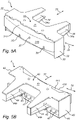
- FIG. 5A a set of co-acting clamping parts (3, 4) is shown.
- An inner clamping part 3 shown in figure 5A is situated on an inner side of suction bucket 7 during use, while an outer clamping parts 3 shown in figure 5B is situated on an outer side of suction bucket 7 during use.
- the two parts are embodied identically so that the rear side of inner clamping part 4, which is invisible in figure 5A , corresponds to the rear side of outer clamping part 4, which is visible in figure 5B .
- Each clamping part (3, 4) comprises substantially a transverse beam (33, 43) which is constructed from an upper plate (31, 41), a lower plate (36, 46) and side plates (32, 42) and which is provided with two I-profiles (34, 44) which have tapering flange plates and which are positioned perpendicularly of the beam and are directed to the rear.
- lower surfaces of the lower flange plates (34a, 44a) of the I-profiles (34, 44) here slide over upper surfaces of the upper flange plates 21a of I-profiles 21.
- the lower surfaces of the lower flange plates (34a, 44a) are provided with slide surfaces (not shown).
- a recess (35, 45) in which an upper flange plate 21a of support frame 2 can be received is arranged on an underside of each clamping part (3, 4).
- the clamping parts (3, 4) and support frame 2 can be coupled to each other in sliding manner, at least in the radial direction 77.
- a rigid coupling between the clamping parts (3, 4) and support frame 2 is obtained in the peripheral direction 78.
- Lower surfaces of the lower plates (36, 46) of the clamping parts (3, 4) support on upper surfaces of the upper flange plates 22a of the I-profiles 22 of support frame 2. This is achieved in that the lower surfaces of the lower flange plates 44a of I-profiles 44 run at a greater height than the lower surfaces of the lower plates (36, 46) of the clamping parts (3, 4). This height difference is substantially equal to the height difference between the upper surfaces of the I-profiles 21 and 22 of support frame 2.
- the clamping parts (3, 4) are configured to connect with a clamping surface (310, 410) against a wall part of suction bucket 7.
- Each clamping surface (310, 410) can for this purpose be curved such that in the clamping position it connects properly to the wall part.
- a simple manner of achieving this is to provide the clamping parts (3, 4) on their clamping side with a wooden covering (311, 411), a surface of which forms the clamping surface (310, 410).
- the coefficient of static friction of wood provides for a good clamping of the generally steel wall part of suction bucket 7.
- the clamping parts (3, 4) are provided with clamping means (37, 47, 38, 39).
- An embodiment comprises openings (37, 47) which are arranged in radial direction 77 through the clamping parts (3, 4) and in which lead screws 38 (see figure 3 ) are received.
- the clamping parts (3, 4) can be shifted along the lead screws (38, 48) by tightening or loosening of nuts 51.
- the clamping parts (3, 4) here shift toward each other from an open position, wherein a lower edge of a suction bucket 7 can be placed between the clamping parts, into a clamping position in which a wall part of suction bucket 7 is clamped between the clamping parts (3, 4). Because in the clamping position the clamping parts (3, 4) can collectively be moved freely over the guide in the radial direction 77, substantially no forces are exerted on suction bucket 7 in radial direction 77, with the exception of clamping forces.
- four devices 1 according to the invention are applied, wherein they are divided regularly over the periphery of the cross-section of suction bucket 7. It is also possible to apply only three devices 1, or conversely more than four.
- Support elements 90 supported by work deck 9 can if desired be applied between devices 1. Suitable support elements 90 comprise wooden blocks or pallets which have been slid under suction bucket 7 and which support a lower edge 79 of suction bucket 7. The generally considerable axial forces in the longitudinal direction 76 of suction bucket 7, generated by the force of gravity, can thus be absorbed. Support elements 90 are preferably also divided regularly over the periphery of the cross-section of suction bucket 7.
- a suction bucket 7 in erected state can be connected to work deck 9 of a transport vessel (not shown).
- the clamping parts (3, 4) are for this purpose placed in an open position by rotating nuts 39 of lead screws 38.
- Suction bucket 7 is then taken up with a suitable crane (not shown) and wall parts of suction bucket 7 are placed between the clamping parts (3, 4).
- the clamping parts (3, 4) are then shifted over the I-profiles in sliding manner in radial direction 77 into a clamping position, in which a wall part of suction bucket 7 is clamped between the covering (311, 411) of the clamping parts (3, 4).
- a lower edge 79 of suction bucket 7 is optionally further supported by arranging a number of support elements 90 on the work deck.
- a lateral load F exerted on a suction bucket 7 is shown in combination with a downward force G on the left-hand side, whereas a lateral load F exerted on a suction bucket 7 is shown in combination with an upward lifting force H on the right-hand side.
- the downward force G is substantially compensated by wood blocks 90, while the lateral load F is absorbed by the two clamping devices 1 which in top view are situated at 12 o'clock and 6 o'clock (each absorbing half of the load F/2).
- clamping devices 1 which in top view are situated at 3 o'clock and 9 o'clock will absorb substantially no load, but will slide freely along the guide (I-profiles 21) and have a freedom of movement in that direction.
Landscapes
- Engineering & Computer Science (AREA)
- Civil Engineering (AREA)
- Paleontology (AREA)
- Structural Engineering (AREA)
- General Engineering & Computer Science (AREA)
- Life Sciences & Earth Sciences (AREA)
- General Life Sciences & Earth Sciences (AREA)
- Mining & Mineral Resources (AREA)
- Combustion & Propulsion (AREA)
- Chemical & Material Sciences (AREA)
- Ocean & Marine Engineering (AREA)
- Mechanical Engineering (AREA)
- Revetment (AREA)
- Load-Engaging Elements For Cranes (AREA)
- Earth Drilling (AREA)
Claims (12)
- Ensemble comprenant au moins deux dispositifs (1) et un dispositif flottant ayant un pont de travail (9) pour la liaison d'une structure tubulaire creuse (7) dans un état érigé au pont de travail (9), laquelle structure tubulaire creuse s'étend dans une direction longitudinale et définit une direction radiale (77) passant perpendiculairement à une paroi périphérique de la structure tubulaire creuse (7), chaque dispositif (1) comprenant deux parties de serrage (3, 4), un guide (21) configuré pour passer, dans l'état installé, dans la direction radiale (77) de la structure tubulaire creuse (7) lorsque la structure tubulaire creuse (7) est reliée au pont de travail (9), et le guide (21) est en outre configuré pour relier les parties de serrage (3, 4) au pont de travail (9), et chaque dispositif comprenant en outre des moyens de serrage (37, 47, 38, 39) pour le décalage des parties de serrage (3, 4) l'une vers l'autre au-dessus du guide (21) dans la direction radiale (77) d'une position ouverte à une position de serrage, dans laquelle une partie de paroi de la structure (7) est serrée entre les parties de serrage (3, 4), dans lequel dans la position de serrage, les parties de serrage (3, 4) peuvent collectivement être déplacées librement au-dessus du guide (21) dans la direction radiale (77), dans lequel les au moins deux dispositifs (1) de l'ensemble sont reliés sur le pont de travail (9) du dispositif flottant le long de la périphérie d'une section transversale de la structure tubulaire creuse (7) lorsque la structure tubulaire creuse (7) est reliée au pont de travail (9), ce qui permet le serrage de parties de paroi de la même structure tubulaire creuse (7) dans l'état érigé dans la direction radiale (77), et l'ensemble comprend en outre des éléments de soutien (90) soutenus par le pont de travail pour le soutien d'un bord inférieur (79) de la structure tubulaire (7).
- Ensemble selon la revendication 1, dans lequel une surface de serrage d'au moins une partie de serrage (3, 4) est incurvée de sorte que, dans la position de serrage, elle se relie à la partie de paroi.
- Ensemble selon la revendication 2, dans lequel au moins une partie de serrage (3, 4) est munie, sur un côté de serrage, d'un revêtement en bois, dont une surface forme la surface de serrage.
- Ensemble selon l'une quelconque des revendications précédentes, dans lequel les parties de serrage (3, 4) comprennent un évidement qui vient en prise sur le guide (21).
- Ensemble selon l'une quelconque des revendications précédentes, comprenant en outre un cadre de soutien pour les parties de serrage (3, 4), lequel cadre de soutien est relié au pont de travail.
- Ensemble selon l'une quelconque des revendications précédentes, dans lequel le guide (21) comprend un rail de guidage.
- Ensemble selon l'une quelconque des revendications précédentes, dans lequel les dispositifs et/ou les éléments de soutien sont répartis uniformément sur la périphérie de la section transversale de la structure tubulaire creuse, lorsque, dans l'état monté, la structure tubulaire creuse est reliée au pont de travail (9).
- Combinaison d'un ensemble selon l'une quelconque des revendications 1 à 7 et d'une structure tubulaire creuse, dans lequel la structure tubulaire creuse est serrée sur le pont de travail (9) du dispositif flottant par les parties de serrage (3, 4).
- Combinaison selon la revendication 8, dans laquelle la structure tubulaire creuse comprend des compartiments d'aspiration d'une chemise de compartiment d'aspiration pour une éolienne.
- Procédé de liaison d'une structure tubulaire creuse (7) dans un état érigé à un pont de travail (9) d'un dispositif flottant, comprenant les étapes de :- la fourniture d'un ensemble selon l'une quelconque des revendications 1 à 7 précédentes ;- le placement des parties de serrage (3, 4) de chaque dispositif (1) dans la position ouverte ;- le soulèvement de la structure tubulaire creuse (7) dans l'état érigé et le placement de parties de paroi de la structure (7) entre les parties de serrage (3, 4) ;- l'utilisation des moyens de serrage (37, 47, 38, 39) pour décaler les parties de serrage (3, 4) l'une vers l'autre au-dessus du guide (21) dans la direction radiale (77) de la position ouverte à une position de serrage, dans laquelle une partie de paroi de la structure tubulaire creuse (7) est serrée entre les parties de serrage (3, 4), dans lequel, dans la position de serrage, les parties de serrage (3, 4) se déplacent collectivement librement au-dessus du guide (21) dans la direction radiale (77),- dans lequel un bord inférieur (79) de la structure tubulaire creuse (7) est soutenu par un certain nombre d'éléments de support (90) qui sont soutenus par le pont de travail (9).
- Procédé selon la revendication 10, dans lequel les dispositifs et/ou les éléments de soutien sont partagés uniformément sur la périphérie de la section transversale de la structure tubulaire creuse.
- Procédé l'une quelconque des revendications 10 à 11, dans lequel la structure tubulaire creuse comprend un compartiment d'aspiration d'une chemise de compartiment d'aspiration pour une éolienne.
Applications Claiming Priority (1)
| Application Number | Priority Date | Filing Date | Title |
|---|---|---|---|
| BE20165371A BE1023471B1 (nl) | 2016-05-20 | 2016-05-20 | Inrichting en werkwijze voor het met een werkdek van een drijvend tuig verbinden van een holle buisvormige structuur in opgerichte toestand |
Publications (2)
| Publication Number | Publication Date |
|---|---|
| EP3246471A1 EP3246471A1 (fr) | 2017-11-22 |
| EP3246471B1 true EP3246471B1 (fr) | 2022-12-07 |
Family
ID=56148036
Family Applications (1)
| Application Number | Title | Priority Date | Filing Date |
|---|---|---|---|
| EP17171379.5A Active EP3246471B1 (fr) | 2016-05-20 | 2017-05-16 | Dispositif et procédé de connexion d'une structure tubulaire creuse dans un état déployé à un travail d'un dispositif flottant |
Country Status (2)
| Country | Link |
|---|---|
| EP (1) | EP3246471B1 (fr) |
| BE (1) | BE1023471B1 (fr) |
Families Citing this family (2)
| Publication number | Priority date | Publication date | Assignee | Title |
|---|---|---|---|---|
| BE1025057B9 (nl) * | 2017-03-16 | 2019-01-08 | Geosea N V | Steunstructuur voor een offshore windturbine en ballasthouder daarvoor |
| CN109837901A (zh) * | 2019-01-22 | 2019-06-04 | 广东精铟海洋工程股份有限公司 | 一种海上风机单体桩基抱桩器 |
Citations (5)
| Publication number | Priority date | Publication date | Assignee | Title |
|---|---|---|---|---|
| US5653556A (en) * | 1995-10-10 | 1997-08-05 | American Piledriving Equipment, Inc. | Clamping apparatus and methods for driving caissons into the earth |
| US7824132B1 (en) * | 2000-08-01 | 2010-11-02 | American Piledriving Equipment, Inc. | Automatically adjustable caisson clamp |
| NL2005087C2 (en) * | 2010-07-15 | 2012-01-17 | Dieseko Group B V | System for driving a large diameter caisson into the ground. |
| WO2015190919A2 (fr) * | 2014-06-10 | 2015-12-17 | Cape Holland Holding B.V. | Dispositif vibrant et procédé pour insérer un élément de fondation dans le sol |
| EP3144213A1 (fr) * | 2015-09-17 | 2017-03-22 | Reel | Procédé pour la pose d'un élément allongé constitutif d'une éolienne, en particulier un mât d'éolienne |
Family Cites Families (1)
| Publication number | Priority date | Publication date | Assignee | Title |
|---|---|---|---|---|
| BE1021930B1 (nl) * | 2014-02-28 | 2016-01-27 | Geosea Nv | Inrichting en werkwijze voor het in een onderwaterbodem aanbrengen van funderingspalen |
-
2016
- 2016-05-20 BE BE20165371A patent/BE1023471B1/nl active
-
2017
- 2017-05-16 EP EP17171379.5A patent/EP3246471B1/fr active Active
Patent Citations (5)
| Publication number | Priority date | Publication date | Assignee | Title |
|---|---|---|---|---|
| US5653556A (en) * | 1995-10-10 | 1997-08-05 | American Piledriving Equipment, Inc. | Clamping apparatus and methods for driving caissons into the earth |
| US7824132B1 (en) * | 2000-08-01 | 2010-11-02 | American Piledriving Equipment, Inc. | Automatically adjustable caisson clamp |
| NL2005087C2 (en) * | 2010-07-15 | 2012-01-17 | Dieseko Group B V | System for driving a large diameter caisson into the ground. |
| WO2015190919A2 (fr) * | 2014-06-10 | 2015-12-17 | Cape Holland Holding B.V. | Dispositif vibrant et procédé pour insérer un élément de fondation dans le sol |
| EP3144213A1 (fr) * | 2015-09-17 | 2017-03-22 | Reel | Procédé pour la pose d'un élément allongé constitutif d'une éolienne, en particulier un mât d'éolienne |
Also Published As
| Publication number | Publication date |
|---|---|
| EP3246471A1 (fr) | 2017-11-22 |
| BE1023471B1 (nl) | 2017-03-29 |
Similar Documents
| Publication | Publication Date | Title |
|---|---|---|
| EP3623645B1 (fr) | Structure d'ancrage d'une tour d'une éolienne et procédé de réalisation d'une connexion à boulon entre des brides de connexion d'une tour d'une éolienne et d'une structure d'ancrage d'une tour d'une éolienne | |
| US11261575B2 (en) | Segmented suction bucket | |
| EP2185816B2 (fr) | Fondation monopieu pour une éolienne située en mer | |
| US10612523B1 (en) | Offshore monopile wind turbine with triangular support structure | |
| US20120107055A1 (en) | Base structure for off-shore wind turbines and method for building thereof | |
| KR101629481B1 (ko) | 해양구조물의 레벨링장치 | |
| KR101573064B1 (ko) | 해상 녹색에너지 발전을 포함하는 기초 파일 시공용 지그 및 이를 이용한 해상 기초구조물 시공 공법 | |
| JP2011157971A (ja) | 洋上風車を支持するための支持構造体 | |
| KR20220122760A (ko) | 풍력 터빈과 같은 하중 구조체를 예를 들어 해저에 지지하기 위한 지지체를 설치하는 방법 | |
| EP3246471B1 (fr) | Dispositif et procédé de connexion d'une structure tubulaire creuse dans un état déployé à un travail d'un dispositif flottant | |
| KR101696031B1 (ko) | 해상풍력발전 하부구조물 | |
| KR20140050186A (ko) | 해상 풍력 발전장치 및 이의 급속 설치방법 | |
| KR101724593B1 (ko) | 전용 바지선을 이용한 풍력발전기의 해상 구축 방법 | |
| NL2028088B1 (en) | Concrete connector body for an offshore wind turbine. | |
| TWI892725B (zh) | 具有豎直柱總成之海上平台 | |
| US11131073B2 (en) | Method for foundation of a transformer platform and transformer platform with at least three piles | |
| EP2472008A1 (fr) | Plate-forme en mer autoélévatrice et son utilisation pour le levage de charges volumineuses et lourdes | |
| CN215252747U (zh) | 一种大型水上施工平台结构 | |
| KR102374485B1 (ko) | 리프팅 잭과 그리퍼를 이용한 내부관입형 해상 지지구조물 연결구조 및 연결방법 | |
| NL2005370C2 (en) | Floating marine structure with suction piles and vessel. | |
| CN113864125A (zh) | 一种新型风机塔筒-导管架过渡段结构 | |
| KR102374486B1 (ko) | 리프팅 잭과 그리퍼를 이용한 외부관입형 해상 지지구조물 연결구조 및 연결방법 | |
| EP1129258A1 (fr) | Construction en mer | |
| KR20240121229A (ko) | 해상 풍력 터빈을 위한 지지 구조체 및 상기 지지 구조체를 설치하기 위한 공정 | |
| CN113202076A (zh) | 一种大型水上施工平台结构及其架设方法 |
Legal Events
| Date | Code | Title | Description |
|---|---|---|---|
| PUAI | Public reference made under article 153(3) epc to a published international application that has entered the european phase |
Free format text: ORIGINAL CODE: 0009012 |
|
| STAA | Information on the status of an ep patent application or granted ep patent |
Free format text: STATUS: THE APPLICATION HAS BEEN PUBLISHED |
|
| AK | Designated contracting states |
Kind code of ref document: A1 Designated state(s): AL AT BE BG CH CY CZ DE DK EE ES FI FR GB GR HR HU IE IS IT LI LT LU LV MC MK MT NL NO PL PT RO RS SE SI SK SM TR |
|
| AX | Request for extension of the european patent |
Extension state: BA ME |
|
| STAA | Information on the status of an ep patent application or granted ep patent |
Free format text: STATUS: REQUEST FOR EXAMINATION WAS MADE |
|
| 17P | Request for examination filed |
Effective date: 20180522 |
|
| RBV | Designated contracting states (corrected) |
Designated state(s): AL AT BE BG CH CY CZ DE DK EE ES FI FR GB GR HR HU IE IS IT LI LT LU LV MC MK MT NL NO PL PT RO RS SE SI SK SM TR |
|
| STAA | Information on the status of an ep patent application or granted ep patent |
Free format text: STATUS: EXAMINATION IS IN PROGRESS |
|
| 17Q | First examination report despatched |
Effective date: 20181025 |
|
| RAP1 | Party data changed (applicant data changed or rights of an application transferred) |
Owner name: DEME OFFSHORE BE N.V. |
|
| GRAP | Despatch of communication of intention to grant a patent |
Free format text: ORIGINAL CODE: EPIDOSNIGR1 |
|
| STAA | Information on the status of an ep patent application or granted ep patent |
Free format text: STATUS: GRANT OF PATENT IS INTENDED |
|
| INTG | Intention to grant announced |
Effective date: 20220719 |
|
| GRAS | Grant fee paid |
Free format text: ORIGINAL CODE: EPIDOSNIGR3 |
|
| GRAA | (expected) grant |
Free format text: ORIGINAL CODE: 0009210 |
|
| STAA | Information on the status of an ep patent application or granted ep patent |
Free format text: STATUS: THE PATENT HAS BEEN GRANTED |
|
| AK | Designated contracting states |
Kind code of ref document: B1 Designated state(s): AL AT BE BG CH CY CZ DE DK EE ES FI FR GB GR HR HU IE IS IT LI LT LU LV MC MK MT NL NO PL PT RO RS SE SI SK SM TR |
|
| REG | Reference to a national code |
Ref country code: GB Ref legal event code: FG4D |
|
| REG | Reference to a national code |
Ref country code: CH Ref legal event code: EP Ref country code: AT Ref legal event code: REF Ref document number: 1536366 Country of ref document: AT Kind code of ref document: T Effective date: 20221215 |
|
| REG | Reference to a national code |
Ref country code: DE Ref legal event code: R096 Ref document number: 602017064315 Country of ref document: DE |
|
| REG | Reference to a national code |
Ref country code: IE Ref legal event code: FG4D |
|
| REG | Reference to a national code |
Ref country code: NL Ref legal event code: FP |
|
| REG | Reference to a national code |
Ref country code: LT Ref legal event code: MG9D |
|
| PG25 | Lapsed in a contracting state [announced via postgrant information from national office to epo] |
Ref country code: SE Free format text: LAPSE BECAUSE OF FAILURE TO SUBMIT A TRANSLATION OF THE DESCRIPTION OR TO PAY THE FEE WITHIN THE PRESCRIBED TIME-LIMIT Effective date: 20221207 Ref country code: NO Free format text: LAPSE BECAUSE OF FAILURE TO SUBMIT A TRANSLATION OF THE DESCRIPTION OR TO PAY THE FEE WITHIN THE PRESCRIBED TIME-LIMIT Effective date: 20230307 Ref country code: LT Free format text: LAPSE BECAUSE OF FAILURE TO SUBMIT A TRANSLATION OF THE DESCRIPTION OR TO PAY THE FEE WITHIN THE PRESCRIBED TIME-LIMIT Effective date: 20221207 Ref country code: FI Free format text: LAPSE BECAUSE OF FAILURE TO SUBMIT A TRANSLATION OF THE DESCRIPTION OR TO PAY THE FEE WITHIN THE PRESCRIBED TIME-LIMIT Effective date: 20221207 Ref country code: ES Free format text: LAPSE BECAUSE OF FAILURE TO SUBMIT A TRANSLATION OF THE DESCRIPTION OR TO PAY THE FEE WITHIN THE PRESCRIBED TIME-LIMIT Effective date: 20221207 |
|
| REG | Reference to a national code |
Ref country code: AT Ref legal event code: MK05 Ref document number: 1536366 Country of ref document: AT Kind code of ref document: T Effective date: 20221207 |
|
| PG25 | Lapsed in a contracting state [announced via postgrant information from national office to epo] |
Ref country code: RS Free format text: LAPSE BECAUSE OF FAILURE TO SUBMIT A TRANSLATION OF THE DESCRIPTION OR TO PAY THE FEE WITHIN THE PRESCRIBED TIME-LIMIT Effective date: 20221207 Ref country code: PL Free format text: LAPSE BECAUSE OF FAILURE TO SUBMIT A TRANSLATION OF THE DESCRIPTION OR TO PAY THE FEE WITHIN THE PRESCRIBED TIME-LIMIT Effective date: 20221207 Ref country code: LV Free format text: LAPSE BECAUSE OF FAILURE TO SUBMIT A TRANSLATION OF THE DESCRIPTION OR TO PAY THE FEE WITHIN THE PRESCRIBED TIME-LIMIT Effective date: 20221207 Ref country code: HR Free format text: LAPSE BECAUSE OF FAILURE TO SUBMIT A TRANSLATION OF THE DESCRIPTION OR TO PAY THE FEE WITHIN THE PRESCRIBED TIME-LIMIT Effective date: 20221207 Ref country code: GR Free format text: LAPSE BECAUSE OF FAILURE TO SUBMIT A TRANSLATION OF THE DESCRIPTION OR TO PAY THE FEE WITHIN THE PRESCRIBED TIME-LIMIT Effective date: 20230308 |
|
| P01 | Opt-out of the competence of the unified patent court (upc) registered |
Effective date: 20230526 |
|
| PG25 | Lapsed in a contracting state [announced via postgrant information from national office to epo] |
Ref country code: SM Free format text: LAPSE BECAUSE OF FAILURE TO SUBMIT A TRANSLATION OF THE DESCRIPTION OR TO PAY THE FEE WITHIN THE PRESCRIBED TIME-LIMIT Effective date: 20221207 Ref country code: RO Free format text: LAPSE BECAUSE OF FAILURE TO SUBMIT A TRANSLATION OF THE DESCRIPTION OR TO PAY THE FEE WITHIN THE PRESCRIBED TIME-LIMIT Effective date: 20221207 Ref country code: PT Free format text: LAPSE BECAUSE OF FAILURE TO SUBMIT A TRANSLATION OF THE DESCRIPTION OR TO PAY THE FEE WITHIN THE PRESCRIBED TIME-LIMIT Effective date: 20230410 Ref country code: EE Free format text: LAPSE BECAUSE OF FAILURE TO SUBMIT A TRANSLATION OF THE DESCRIPTION OR TO PAY THE FEE WITHIN THE PRESCRIBED TIME-LIMIT Effective date: 20221207 Ref country code: CZ Free format text: LAPSE BECAUSE OF FAILURE TO SUBMIT A TRANSLATION OF THE DESCRIPTION OR TO PAY THE FEE WITHIN THE PRESCRIBED TIME-LIMIT Effective date: 20221207 Ref country code: AT Free format text: LAPSE BECAUSE OF FAILURE TO SUBMIT A TRANSLATION OF THE DESCRIPTION OR TO PAY THE FEE WITHIN THE PRESCRIBED TIME-LIMIT Effective date: 20221207 |
|
| PG25 | Lapsed in a contracting state [announced via postgrant information from national office to epo] |
Ref country code: SK Free format text: LAPSE BECAUSE OF FAILURE TO SUBMIT A TRANSLATION OF THE DESCRIPTION OR TO PAY THE FEE WITHIN THE PRESCRIBED TIME-LIMIT Effective date: 20221207 Ref country code: IS Free format text: LAPSE BECAUSE OF FAILURE TO SUBMIT A TRANSLATION OF THE DESCRIPTION OR TO PAY THE FEE WITHIN THE PRESCRIBED TIME-LIMIT Effective date: 20230407 Ref country code: AL Free format text: LAPSE BECAUSE OF FAILURE TO SUBMIT A TRANSLATION OF THE DESCRIPTION OR TO PAY THE FEE WITHIN THE PRESCRIBED TIME-LIMIT Effective date: 20221207 |
|
| REG | Reference to a national code |
Ref country code: DE Ref legal event code: R097 Ref document number: 602017064315 Country of ref document: DE |
|
| PLBE | No opposition filed within time limit |
Free format text: ORIGINAL CODE: 0009261 |
|
| STAA | Information on the status of an ep patent application or granted ep patent |
Free format text: STATUS: NO OPPOSITION FILED WITHIN TIME LIMIT |
|
| PG25 | Lapsed in a contracting state [announced via postgrant information from national office to epo] |
Ref country code: DK Free format text: LAPSE BECAUSE OF FAILURE TO SUBMIT A TRANSLATION OF THE DESCRIPTION OR TO PAY THE FEE WITHIN THE PRESCRIBED TIME-LIMIT Effective date: 20221207 |
|
| 26N | No opposition filed |
Effective date: 20230908 |
|
| PG25 | Lapsed in a contracting state [announced via postgrant information from national office to epo] |
Ref country code: SI Free format text: LAPSE BECAUSE OF FAILURE TO SUBMIT A TRANSLATION OF THE DESCRIPTION OR TO PAY THE FEE WITHIN THE PRESCRIBED TIME-LIMIT Effective date: 20221207 |
|
| REG | Reference to a national code |
Ref country code: CH Ref legal event code: PL |
|
| PG25 | Lapsed in a contracting state [announced via postgrant information from national office to epo] |
Ref country code: MC Free format text: LAPSE BECAUSE OF FAILURE TO SUBMIT A TRANSLATION OF THE DESCRIPTION OR TO PAY THE FEE WITHIN THE PRESCRIBED TIME-LIMIT Effective date: 20221207 |
|
| GBPC | Gb: european patent ceased through non-payment of renewal fee |
Effective date: 20230516 |
|
| PG25 | Lapsed in a contracting state [announced via postgrant information from national office to epo] |
Ref country code: MC Free format text: LAPSE BECAUSE OF FAILURE TO SUBMIT A TRANSLATION OF THE DESCRIPTION OR TO PAY THE FEE WITHIN THE PRESCRIBED TIME-LIMIT Effective date: 20221207 Ref country code: LU Free format text: LAPSE BECAUSE OF NON-PAYMENT OF DUE FEES Effective date: 20230516 Ref country code: LI Free format text: LAPSE BECAUSE OF NON-PAYMENT OF DUE FEES Effective date: 20230531 Ref country code: CH Free format text: LAPSE BECAUSE OF NON-PAYMENT OF DUE FEES Effective date: 20230531 |
|
| REG | Reference to a national code |
Ref country code: IE Ref legal event code: MM4A |
|
| PG25 | Lapsed in a contracting state [announced via postgrant information from national office to epo] |
Ref country code: IE Free format text: LAPSE BECAUSE OF NON-PAYMENT OF DUE FEES Effective date: 20230516 |
|
| PG25 | Lapsed in a contracting state [announced via postgrant information from national office to epo] |
Ref country code: IE Free format text: LAPSE BECAUSE OF NON-PAYMENT OF DUE FEES Effective date: 20230516 Ref country code: GB Free format text: LAPSE BECAUSE OF NON-PAYMENT OF DUE FEES Effective date: 20230516 |
|
| PG25 | Lapsed in a contracting state [announced via postgrant information from national office to epo] |
Ref country code: IT Free format text: LAPSE BECAUSE OF FAILURE TO SUBMIT A TRANSLATION OF THE DESCRIPTION OR TO PAY THE FEE WITHIN THE PRESCRIBED TIME-LIMIT Effective date: 20221207 |
|
| PG25 | Lapsed in a contracting state [announced via postgrant information from national office to epo] |
Ref country code: BG Free format text: LAPSE BECAUSE OF FAILURE TO SUBMIT A TRANSLATION OF THE DESCRIPTION OR TO PAY THE FEE WITHIN THE PRESCRIBED TIME-LIMIT Effective date: 20221207 |
|
| PG25 | Lapsed in a contracting state [announced via postgrant information from national office to epo] |
Ref country code: BG Free format text: LAPSE BECAUSE OF FAILURE TO SUBMIT A TRANSLATION OF THE DESCRIPTION OR TO PAY THE FEE WITHIN THE PRESCRIBED TIME-LIMIT Effective date: 20221207 |
|
| PGFP | Annual fee paid to national office [announced via postgrant information from national office to epo] |
Ref country code: NL Payment date: 20250507 Year of fee payment: 9 |
|
| PGFP | Annual fee paid to national office [announced via postgrant information from national office to epo] |
Ref country code: DE Payment date: 20250506 Year of fee payment: 9 |
|
| PGFP | Annual fee paid to national office [announced via postgrant information from national office to epo] |
Ref country code: BE Payment date: 20250507 Year of fee payment: 9 |
|
| PGFP | Annual fee paid to national office [announced via postgrant information from national office to epo] |
Ref country code: FR Payment date: 20250515 Year of fee payment: 9 |
|
| PG25 | Lapsed in a contracting state [announced via postgrant information from national office to epo] |
Ref country code: CY Free format text: LAPSE BECAUSE OF FAILURE TO SUBMIT A TRANSLATION OF THE DESCRIPTION OR TO PAY THE FEE WITHIN THE PRESCRIBED TIME-LIMIT; INVALID AB INITIO Effective date: 20170516 |
|
| PG25 | Lapsed in a contracting state [announced via postgrant information from national office to epo] |
Ref country code: HU Free format text: LAPSE BECAUSE OF FAILURE TO SUBMIT A TRANSLATION OF THE DESCRIPTION OR TO PAY THE FEE WITHIN THE PRESCRIBED TIME-LIMIT; INVALID AB INITIO Effective date: 20170516 |
|
| PG25 | Lapsed in a contracting state [announced via postgrant information from national office to epo] |
Ref country code: TR Free format text: LAPSE BECAUSE OF FAILURE TO SUBMIT A TRANSLATION OF THE DESCRIPTION OR TO PAY THE FEE WITHIN THE PRESCRIBED TIME-LIMIT Effective date: 20221207 |