EP3246475B1 - Dispositif de sortie d'eau pour l'éau filtrée et l'éau potable - Google Patents
Dispositif de sortie d'eau pour l'éau filtrée et l'éau potable Download PDFInfo
- Publication number
- EP3246475B1 EP3246475B1 EP16002645.6A EP16002645A EP3246475B1 EP 3246475 B1 EP3246475 B1 EP 3246475B1 EP 16002645 A EP16002645 A EP 16002645A EP 3246475 B1 EP3246475 B1 EP 3246475B1
- Authority
- EP
- European Patent Office
- Prior art keywords
- outlet
- disposed
- tap water
- switch valve
- filtered water
- Prior art date
- Legal status (The legal status is an assumption and is not a legal conclusion. Google has not performed a legal analysis and makes no representation as to the accuracy of the status listed.)
- Active
Links
Images


Classifications
-
- E—FIXED CONSTRUCTIONS
- E03—WATER SUPPLY; SEWERAGE
- E03C—DOMESTIC PLUMBING INSTALLATIONS FOR FRESH WATER OR WASTE WATER; SINKS
- E03C1/00—Domestic plumbing installations for fresh water or waste water; Sinks
- E03C1/02—Plumbing installations for fresh water
- E03C1/04—Water-basin installations specially adapted to wash-basins or baths
- E03C1/0404—Constructional or functional features of the spout
-
- F—MECHANICAL ENGINEERING; LIGHTING; HEATING; WEAPONS; BLASTING
- F16—ENGINEERING ELEMENTS AND UNITS; GENERAL MEASURES FOR PRODUCING AND MAINTAINING EFFECTIVE FUNCTIONING OF MACHINES OR INSTALLATIONS; THERMAL INSULATION IN GENERAL
- F16K—VALVES; TAPS; COCKS; ACTUATING-FLOATS; DEVICES FOR VENTING OR AERATING
- F16K11/00—Multiple-way valves, e.g. mixing valves; Pipe fittings incorporating such valves
- F16K11/10—Multiple-way valves, e.g. mixing valves; Pipe fittings incorporating such valves with two or more closure members not moving as a unit
- F16K11/20—Multiple-way valves, e.g. mixing valves; Pipe fittings incorporating such valves with two or more closure members not moving as a unit operated by separate actuating members
- F16K11/22—Multiple-way valves, e.g. mixing valves; Pipe fittings incorporating such valves with two or more closure members not moving as a unit operated by separate actuating members with an actuating member for each valve, e.g. interconnected to form multiple-way valves
-
- B—PERFORMING OPERATIONS; TRANSPORTING
- B01—PHYSICAL OR CHEMICAL PROCESSES OR APPARATUS IN GENERAL
- B01D—SEPARATION
- B01D35/00—Filtering devices having features not specifically covered by groups B01D24/00 - B01D33/00, or for applications not specifically covered by groups B01D24/00 - B01D33/00; Auxiliary devices for filtration; Filter housing constructions
- B01D35/02—Filters adapted for location in special places, e.g. pipe-lines, pumps, stop-cocks
- B01D35/04—Plug, tap, or cock filters filtering elements mounted in or on a faucet
-
- F—MECHANICAL ENGINEERING; LIGHTING; HEATING; WEAPONS; BLASTING
- F16—ENGINEERING ELEMENTS AND UNITS; GENERAL MEASURES FOR PRODUCING AND MAINTAINING EFFECTIVE FUNCTIONING OF MACHINES OR INSTALLATIONS; THERMAL INSULATION IN GENERAL
- F16K—VALVES; TAPS; COCKS; ACTUATING-FLOATS; DEVICES FOR VENTING OR AERATING
- F16K27/00—Construction of housing; Use of materials therefor
-
- B—PERFORMING OPERATIONS; TRANSPORTING
- B01—PHYSICAL OR CHEMICAL PROCESSES OR APPARATUS IN GENERAL
- B01D—SEPARATION
- B01D2201/00—Details relating to filtering apparatus
- B01D2201/16—Valves
-
- E—FIXED CONSTRUCTIONS
- E03—WATER SUPPLY; SEWERAGE
- E03C—DOMESTIC PLUMBING INSTALLATIONS FOR FRESH WATER OR WASTE WATER; SINKS
- E03C2201/00—Details, devices or methods not otherwise provided for
- E03C2201/40—Arrangement of water treatment devices in domestic plumbing installations
-
- E—FIXED CONSTRUCTIONS
- E03—WATER SUPPLY; SEWERAGE
- E03C—DOMESTIC PLUMBING INSTALLATIONS FOR FRESH WATER OR WASTE WATER; SINKS
- E03C2201/00—Details, devices or methods not otherwise provided for
- E03C2201/40—Arrangement of water treatment devices in domestic plumbing installations
- E03C2201/45—Arrangement of water treatment devices in domestic plumbing installations for carbonated water
Definitions
- the present invention relates to an outlet mechanism, particularly to an outlet mechanism with filtered water and tap water outlet modes.
- Taps are widely used in washrooms of families, hotels, restaurants, or in basins and water tanks of kitchens. People cares more and more about the health, water for cooking, washing fruits and vegetables and drinking needs to be filtered to use.
- taps with filtering function in the market There are taps with filtering function in the market. However, these taps only outlet filtered water. Water for washing products, hands or clothes needn't to be filtered. This kind of filtering tap with single function in long and high frequency usage would shorten the filtering element's service life, resulting in a waste of resource.
- DE 20 2006 004 399 U relates to a fluid armature for providing one or more fluids, wherein the fluid armature comprises a colour device for colouring of one or more fluids.
- the colouring of the fluid may be provided by illumination of the fluid and may indicate a temperature such as hot or cold of the fluid.
- Each fluid is guided through a conduit inside an armature tube and is illuminated shortly before leaving an outlet body of the tube.
- the document EP 0 896 176 A2 describes a faucet spout assembly for selectively dispensing treated or filtered water and untreated or unfiltered water.
- the faucet includes a valve assembly which is connectable to a handle 50 to facilitate control a volume and temperature of water to be dispensed by the faucet.
- the faucet spout assembly comprises a selector knob 62, which is formed with a cup-shaped body 308.
- the position of the selector knob 62 which is rotatable,determines the selection of unfiltered or filtered water.
- the document US 2005/0189023 A1 relates to a dual stand type faucet used in kitchen.
- a control valve 21 serves for controlling the mixing of cold and hot water.
- a handle 46 is installed in front of a water control stud 4, which can control a supply of clean water directly.
- the document US 6 220 298 B1 describes a faucet comprising a tubular body 11 and a head member 4.
- the head member 4 has a first section 41 and a second section 42, which is connected to the first section 42 with an included angle defined there between.
- Valve means are pivotably received in the second section 42 and has a rotor 54 pivotably received in the second section 42 of the head member 4.
- the present invention is provided with an outlet mechanism with filtered water and tap water outlet modes, which applies two independent outlet switches to respectively control two outlet modes to reduce the occurring of misoperation.
- An outlet mechanism with filtered water and tap water outlet modes comprising: an inlet body and an outlet body; the inlet body is connected to the outlet body, which is disposed independently with a tap water outlet passage and a filtered water outlet passage inside; a first outlet control switch an a second outlet controls switch be i ng respectively used to control the open and close of the tap water outlet passage and the filtered water outlet passage; the first outlet control switch is disposed on the inlet body, the second outlet control switch is disposed on the outlet body; and an outlet device being disposed at the end of the outlet body; the outlet device is disposed independently with a first outlet and a second outlet; the first outlet and the second outlet are respectively connected to the tap water outlet passage and the filtered water outlet passage, wherein the second outlet control switch comprises a switch valve button, the switch valve button is pressed to open or close the filtered water outlet passage.
- the outlet body comprises a support pipe and an outlet joint component; the support pipe is connected between the outlet joint component and the inlet body; the front end of the outlet joint component is disposed with a tap water flowing hole and a filtered water flowing hole, which form the tap water outlet passage and the filtered outlet passage; the end of the outlet joint component is disposed with a first opening; the side wall of the outlet joint component is further disposed with a second outlet vertical to the side wall.
- the switch valve component is disposed in the outlet joint component, the switch valve button is connected to one end of the switch valve component in transmitting way and is exposed out of the first open i ng.
- the switch valve component is further disposed with a sealing element; when the switch valve button is pressed, the sealing element moves in the switch valve component, such that the filtered water flowing hole is connected to the second opening or is closed by the sealing element.
- it comprises one or more tap water flowing hole.
- the switch valve component further comprises a push bar, one end of the push bar is connected to the switch valve button in transmitting way, the side wall of the other end is arranged with protruding blocks with interval, the end of the protruding block is configured to be an incline surface.
- the sealing element is coaxial to the push bar, the sealing element is disposed with a sealing ring vertical to the axial direction; the side of the sealing ring faced to the push bar is disposed with a plural ity of bosses; the side of the boss faced to the protruding block is disposed with a guiding surface coupled to the incline surface.
- the outlet device is disposed in the second opening; the first outlet and the second outlet are arranged in surrounding way, the first outlet surrounds the external periphery of the second outlet.
- the inlet body comprises a body base and an independent valve spool base disposed in the body base; the independent valve spool base is disposed independently with a filtered water inlet and a tap water inlet, the filtered water inlet is connected to the filtered water outlet passage; the side wall of the independent valve spool base is disposed with a tap water outlet; the first outlet control switch is disposed between the tap water outlet and the tap water flowing hole; when the first outlet control switch is switched on or off, the tap water outlet is connected or disconnected to the tap water flowing hole.
- it comprises two tap water inlets: a cool water inlet and a hot water inlet.
- an outlet mechanism with filtered water and tap water outlet modes comprises:
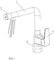
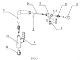
- An inlet body 2 an outlet body 1, an outlet device 3, a first outlet control switch 4 and a second outlet control switch 5; the inlet body 2 is connected to the outlet body 1, which is disposed independently with a tap water outlet passage 13 and a filtered water outlet passage 14 inside;
- the outlet body 1 comprises a support pipe 11 and an outlet joint component 12; the support pipe 11 is connected between the outlet joint component 12 and the inlet body 2; the front end of the outlet joint component 12 is disposed with a tap water flowing hole 122 and a filtered water flowing hole 121, which form the tap water outlet passage 13 and the filtered outlet passage 14; the end of the outlet joint component 12 is disposed with a first opening 123; the side wall of the outlet joint component 12 is further disposed with a second outlet 124 vertical to the side wall.
- the outlet device 3 is disposed in the second opening 124, the outlet device 3 is disposed independently with a first outlet 31 and a second outlet 32; the first outlet 31 and the second outlet 32 are respectively connected to the tap water outlet passage 13 and the filtered water outlet passage 14.
- the first outlet 31 and the second outlet 32 are arranged in surrounding way, the first outlet 31 surrounds the external periphery of the second outlet 32.
- the first outlet control switch 4 is disposed on the inlet body 2
- the second outlet control switch 5 is disposed on the outlet body 1; the switches are respectively used to control the open and close of the tap water outlet passage 13 and the filtered water outlet passage 14.
- the second outlet control switch 5 comprises a switch valve component 51 and a switch valve button 52; the switch valve component 51 is disposed in the outlet joint component 12, the switch valve button 52 is connected to one end of the switch valve component 51 in transmitting way and is exposed out of the first opening 123.
- the switch valve component 51 is further disposed with a push bar 53 and a sealing element 54, one end of the push bar 53 is connected to the switch valve button 52 in transmitting way, the side wall of the other end is arranged with protruding blocks 531 with interval, the end of the protruding block 531 is configured to be an incline surface.
- the sealing element 54 is coaxial to the push bar 53, the sealing element 54 is disposed with a sealing ring 541 vertical to the axial direction; the side of the sealing ring 541 faced to the push bar is disposed with a plurality of bosses 542; the side of the boss 542 faced to the protruding block 531 is disposed with a guiding surface 543 coupled to the incline surface.
- the inlet body 2 comprises a body base 21 and an independent valve spool base 22 disposed in the body base 21;
- the independent valve spool base 22 is disposed independently with a filtered water inlet 221 and a tap water inlet 222, the filtered water inlet 221 is connected to the filtered water outlet passage 14; the side wall of the independent valve spool base is disposed with a tap water outlet 223; the first outlet control switch 4 is disposed between the tap water outlet 223 and the tap water flowing hole 122; when the first outlet control switch 4 is switched on or off, the tap water outlet 223 is connected or disconnected to the tap water flowing hole122. Therefore, the tap water outlet passage 13 is controlled by the first outlet control switch 4.
- the tap water outlet passage 13 is adjustable, which satisfies the requirement and using habit.
- the tap water outlet passage 13 is one or more than one as well, two preferred, such to guarantee the outlet volume of the tap water.
- the outlet mechanism with filtered water and tap water outlet modes comprises independent first outlet contro I switch and second outlet control switch to respectively control the tap water outlet and filtered water outlet; in addition, the first outlet control switch is disposed on the inlet body, the second outlet control switch is disposed on the outlet body, such that the user can separate the two switches clearly, thus efficiently avoiding misoperation.
- outlet mechanism with filtered water and tap water outlet modes is provided that the filtered water ad the tap water share one outlet device, the outlet device is disposed with independent filtered water outlet and tap water outlet, such to guarantee an clean and attractive appearance of the outlet mechanism and to ensure the outlet waterways of the filtered water and the tap water not influencing each other, thus ensuring the outlet consistency of each outlet mode.
- the present invention is provided with an outlet mechanism with filtered water and tap water outlet modes, comprising: an inlet body and an outlet body; the inlet body is connected to the outlet body, which is disposed independently with a tap water outlet passage and a filtered water outlet passage inside; a first outlet control switch an a second outlet controls switch being respectively used to control the open and close of the tap water outlet passage and the filtered water outlet passage; the first outlet control switch is disposed on the inlet body, the second outlet control switch is disposed on the outlet body; and an outlet dev i ce be i ng d i sposed at the end of the outlet body; the outlet device is disposed independently with a first outlet and a second outlet; the first outlet and the second outlet are respectively connected to the tap water out let passage and the filtered water outlet passage.
- the present invention is provided with an outlet mechanism with filtered water and tap water outlet modes, which applies two independent outlet switches to respectively control two outlet modes to reduce the occurring of misoperation.
Landscapes
- Engineering & Computer Science (AREA)
- General Engineering & Computer Science (AREA)
- Water Supply & Treatment (AREA)
- Health & Medical Sciences (AREA)
- Life Sciences & Earth Sciences (AREA)
- Hydrology & Water Resources (AREA)
- Public Health (AREA)
- Mechanical Engineering (AREA)
- Chemical & Material Sciences (AREA)
- Chemical Kinetics & Catalysis (AREA)
- Domestic Plumbing Installations (AREA)
- Water Treatment By Sorption (AREA)
Claims (11)
- Mécanisme de sortie avec des modes de sortie eau filtrée et eau du robinet, ledit mécanisme comprenant ;
un corps d'entrée (2) et un corps de sortie (1) ; le corps d'entrée (2) étant relié au corps de sortie (1),
le corps de sortie étant pourvu à l'intérieur, indépendamment, d'un passage de sortie d'eau du robinet (13) et d'un passage de sortie d'eau filtrée (14) ;
un premier commutateur de commande de sortie (4) et un deuxième commutateur de commande de sortie (5) étant utilisés respectivement pour commander l'ouverture et la fermeture du passage de sortie d'eau du robinet (13) et du passage de sortie d'eau filtrée (14) ; le premier commutateur de commande de sortie (4) étant disposé sur le corps d'entrée (2), le deuxième commutateur de commande de sortie (5) étant disposé sur le corps de sortie (1) ; et
un dispositif de sortie (3) étant disposé à l'extrémité du corps de sortie (1) ; caractérisé en ce que le dispositif de sortie (3) est disposé indépendamment avec une première sortie (31) et une deuxième sortie (32) ; la première sortie (31) et la deuxième sortie (32) sont reliées respectivement au passage de sortie d'eau du robinet (13) et au passage de sortie d'eau filtrée (14),
dans lequel le deuxième commutateur de commande de sortie (5) comprend un bouton de vanne de commutateur (52), le bouton de vanne de commutateur (52) étant pressé pour ouvrir ou fermer le passage de sortie d'eau filtrée (14). - Mécanisme de sortie selon la revendication 1,
dans lequel le corps de sortie (1) comprend un tuyau de support (11) et un composant de joint de sortie (12) ; le tuyau de support (11) est relié entre le composant de joint de sortie (12) et le corps d'entrée (2) ; une extrémité avant du composant de joint de sortie (12) est disposée avec un trou d'écoulement d'eau du robinet (122) et un trou d'écoulement d'eau filtrée (121) qui forment le passage de sortie d'eau du robinet (13) et le passage de sortie d'eau filtrée (14) ; l'autre extrémité du composant de joint de sortie (12) est disposée avec une première ouverture (123) ; une paroi latérale du composant de joint de sortie (12) est en outre disposée avec une deuxième ouverture (124) verticale par rapport à la paroi latérale. - Mécanisme de sortie selon la revendication 2,
dans lequel le deuxième commutateur de commande de sortie (5) comprend un composant de vanne de commutateur (51) et le bouton de vanne de commutateur (52) ; le composant de vanne de commutateur (51) est disposé dans le composant de joint de sortie (12), le bouton de vanne de commutateur (52) est relié à une extrémité du composant de vanne de commutateur (51) en permettant une transmission et est exposé hors de la première ouverture (123). - Mécanisme de sortie selon la revendication 3,
dans lequel le composant de vanne de commutateur (51) est en outre disposé avec un élément d'étanchéité (54) ; quand le bouton de vanne de commutateur (52) est pressé, l'élément d'étanchéité (54) se déplace dans le composant de vanne de commutateur (51), de sorte que le trou d'écoulement d'eau filtrée (121) soit relié à une deuxième ouverture (124) ou soit fermé par l'élément d'étanchéité (54). - Mécanisme de sortie selon la revendication 2, comprenant une pluralité de trous d'écoulement d'eau du robinet (122).
- Mécanisme de sortie selon l'une ou plusieurs des revendications 3 à 5, dans lequel le composant de vanne de commutateur (51) comprend en outre une barre de poussée (53), une extrémité de la barre de poussée (53) est reliée au bouton de vanne de commutateur (52) en permettant une transmission, la paroi latérale de l'autre extrémité de la barre de poussée (53) est arrangée avec des blocs saillants (531) avec intervalle, l'extrémité des blocs saillants (531) étant configurée pour être une surface inclinée.
- Mécanisme de sortie selon la revendication 6,
dans lequel l'élément d'étanchéité (54) est coaxial par rapport à la barre de poussée (53), l'élément d'étanchéité (54) est disposé avec une bague d'étanchéité (541) verticale par rapport à la direction axiale; le côté de la bague d'étanchéité (541) dirigé vers la barre de poussée (53) est disposé avec une pluralité de bosses (542) ; le côté des bosses (542) dirigé vers les blocs saillants (531) est disposé avec une surface de guidage (543) couplée à la surface inclinée. - Mécanisme de sortie selon la revendication 2 ou toute revendication dépendante de celle-ci,
dans lequel le dispositif de sortie (3) est disposé dans la deuxième ouverture (124) ; la première sortie (31) et la deuxième sortie (32) sont arrangées de manière entourante, la première sortie (31) entoure la périphérie externe de la deuxième sortie (32). - Mécanisme de sortie selon la revendication 2 ou toute revendication dépendante de celle-ci,
dans lequel le corps d'entrée (2) comprend une base de corps (21) et une base de bobine de vanne indépendante (22) disposée dans la base de corps (21) ;
la base de bobine de vanne indépendante (22) est disposée indépendamment avec une entrée d'eau filtrée (221) et une entrée d'eau du robinet (222), l'entrée d'eau filtrée (221) est reliée au passage de sortie d'eau filtrée (14) ; la paroi latérale de la base de bobine de vanne indépendante (22) est disposée avec une sortie d'eau du robinet (223) ; le premier commutateur de commande de sortie (4) est disposé entre la sortie d'eau du robinet (223) et le trou d'écoulement d'eau du robinet (122) ; quand le premier commutateur de commande de sortie (4) est mis sur marche ou arrêt, la sortie d'eau du robinet (223) est reliée au trou d'écoulement d'eau du robinet (122) ou déconnectée de celui-ci. - Mécanisme de sortie selon la revendication 9,
comprenant deux entrées d'eau du robinet (222) ; une entrée d'eau froide et une entrée d'eau chaude. - Mécanisme de sortie selon l'une ou plusieurs des revendications 4 à 10, caractérisé en ce que lorsque le bouton de vanne de commutateur (52) est pressé le trou d'écoulement d'eau filtrée (121) du composant de joint de sortie (12) est relié à la deuxième ouverture (124) et lorsque le bouton de vanne de commutateur (52) est pressé à nouveau, l'élément d'étanchéité (54) se repositionne, et le trou d'écoulement d'eau filtrée (121) est déconnecté de la deuxième ouverture (124).
Applications Claiming Priority (1)
| Application Number | Priority Date | Filing Date | Title |
|---|---|---|---|
| CN201610324319.9A CN107387816A (zh) | 2016-05-16 | 2016-05-16 | 一种具备过滤水和普通水两种出水模式的出水机构 |
Publications (2)
| Publication Number | Publication Date |
|---|---|
| EP3246475A1 EP3246475A1 (fr) | 2017-11-22 |
| EP3246475B1 true EP3246475B1 (fr) | 2021-08-04 |
Family
ID=57758377
Family Applications (1)
| Application Number | Title | Priority Date | Filing Date |
|---|---|---|---|
| EP16002645.6A Active EP3246475B1 (fr) | 2016-05-16 | 2016-12-13 | Dispositif de sortie d'eau pour l'éau filtrée et l'éau potable |
Country Status (3)
| Country | Link |
|---|---|
| US (1) | US10400428B2 (fr) |
| EP (1) | EP3246475B1 (fr) |
| CN (1) | CN107387816A (fr) |
Families Citing this family (20)
| Publication number | Priority date | Publication date | Assignee | Title |
|---|---|---|---|---|
| USD829305S1 (en) * | 2016-07-01 | 2018-09-25 | Xiamen Solex High-Tech Industries Co., Ltd. | Water purifying tap |
| CN108223878A (zh) * | 2018-01-25 | 2018-06-29 | 珠海普乐美厨卫有限公司 | 一种按键式多功能净水龙头 |
| CN109058551A (zh) * | 2018-11-02 | 2018-12-21 | 江门市依洛娜卫浴有限公司 | 一种多功能水龙头 |
| CN109723862A (zh) * | 2019-01-11 | 2019-05-07 | 玉环达丰环保设备有限公司 | 具有双入水功能的紫外线杀菌龙头 |
| USD913434S1 (en) * | 2019-02-05 | 2021-03-16 | Grohe Ag | Faucet |
| USD913435S1 (en) * | 2019-02-05 | 2021-03-16 | Grohe Ag | Faucet |
| USD915563S1 (en) * | 2019-02-05 | 2021-04-06 | Grohe Ag | Faucet handspray |
| USD914164S1 (en) * | 2019-03-04 | 2021-03-23 | Grohe Ag | Faucet |
| USD926941S1 (en) * | 2019-03-05 | 2021-08-03 | Amfag S.R.L. | Faucet |
| CN113833877B (zh) * | 2021-10-21 | 2025-11-21 | 九牧厨卫股份有限公司 | 一种水龙头 |
| USD1066602S1 (en) * | 2022-06-16 | 2025-03-11 | Vizio Gmbh | Water tap |
| USD1043918S1 (en) * | 2022-10-12 | 2024-09-24 | Assa Abloy Americas Residential Inc. | Faucet |
| USD1049316S1 (en) * | 2022-10-21 | 2024-10-29 | Globe Union Industrial Corp. | Faucet |
| DE102022130727A1 (de) * | 2022-11-21 | 2024-05-23 | Franz Joseph Schütte GmbH | Sanitärarmatur |
| CN120548395A (zh) * | 2023-01-30 | 2025-08-26 | 富俊水创新有限责任公司 | 具有拉出式喷头的水龙头系统 |
| USD1105358S1 (en) * | 2024-07-16 | 2025-12-09 | Shenzhen Aquavil Technology Co., Ltd. | Multi-function tap |
| USD1121111S1 (en) * | 2024-12-18 | 2026-03-31 | Xiamen Lota International Co., Ltd. | Faucet |
| USD1117641S1 (en) * | 2024-12-19 | 2026-03-10 | Xiamen Lota International Co., Ltd. | Faucet |
| USD1121780S1 (en) * | 2024-12-19 | 2026-04-07 | Xiamen Lota International Co., Ltd. | Faucet |
| USD1117640S1 (en) * | 2024-12-31 | 2026-03-10 | Zhongyi Mo | Faucet |
Family Cites Families (15)
| Publication number | Priority date | Publication date | Assignee | Title |
|---|---|---|---|---|
| CH421640A (de) * | 1963-04-11 | 1966-09-30 | Kadron Gmbh | Gehäuse für Blockwegeventile |
| US6179130B1 (en) * | 1997-08-08 | 2001-01-30 | Emhart Inc. | Faucet spout assembly |
| US6220298B1 (en) * | 1999-03-23 | 2001-04-24 | Mu Lin Wu | Faucet having a filter member received therein |
| EP1557501A1 (fr) * | 2004-01-26 | 2005-07-27 | Fabrizio Nobili | Assemblage de distribution de l'eau traitée, robinet et tuyau d'alimentation associé |
| US6941971B1 (en) * | 2004-02-27 | 2005-09-13 | Yu-You Hsien | Dual use stand type faucet used in kitchen |
| GB0509348D0 (en) * | 2005-05-09 | 2005-06-15 | Astracast Plc | A water tap |
| JP4710472B2 (ja) * | 2005-07-29 | 2011-06-29 | トヨタ自動車株式会社 | 車両情報処理装置、車両情報処理装置の検査方法、および車両情報処理装置のid登録方法 |
| DE202006004399U1 (de) * | 2006-03-17 | 2007-07-26 | Bolderheij, Fok Cornelis | Fluidarmatur mit Farbgebungseinrichtung |
| US20070235091A1 (en) * | 2006-04-06 | 2007-10-11 | Yoav Granot | Water tap assembly having a pull-out water-discharge head |
| CN101749457A (zh) * | 2008-12-02 | 2010-06-23 | 张庆柳 | 自动节水龙头 |
| CN101526154A (zh) * | 2009-03-31 | 2009-09-09 | 温州帝威斯感应洁具有限公司 | 感应式与机械式竖向按钮两用节水龙头 |
| CN204573203U (zh) * | 2015-01-27 | 2015-08-19 | 厦门天楚工贸有限公司 | 一种多功能水龙头 |
| CN204664495U (zh) * | 2015-03-27 | 2015-09-23 | 珠海威锦卫浴设备有限公司 | 一种净化水龙头 |
| CN204852459U (zh) * | 2015-06-02 | 2015-12-09 | 厦门建霖工业有限公司 | 厨房混合水、净水二合一龙头 |
| CN205781085U (zh) * | 2016-05-16 | 2016-12-07 | 厦门松霖科技有限公司 | 具备过滤水和普通水两种出水模式的出水机构 |
-
2016
- 2016-05-16 CN CN201610324319.9A patent/CN107387816A/zh active Pending
- 2016-12-13 EP EP16002645.6A patent/EP3246475B1/fr active Active
- 2016-12-13 US US15/377,544 patent/US10400428B2/en active Active
Non-Patent Citations (1)
| Title |
|---|
| None * |
Also Published As
| Publication number | Publication date |
|---|---|
| US20170328044A1 (en) | 2017-11-16 |
| US10400428B2 (en) | 2019-09-03 |
| EP3246475A1 (fr) | 2017-11-22 |
| CN107387816A (zh) | 2017-11-24 |
Similar Documents
| Publication | Publication Date | Title |
|---|---|---|
| EP3246475B1 (fr) | Dispositif de sortie d'eau pour l'éau filtrée et l'éau potable | |
| CN1787856B (zh) | 多出水形态的可拉出的喷头 | |
| AU2022246419B2 (en) | Mixing tap for dispensing water | |
| CN108368696B (zh) | 集成的龙头过滤系统 | |
| EP2841656B1 (fr) | Robinet et ensemble comprenant un dispositif d'eau en ébullition et un tel robinet | |
| US8985147B2 (en) | Fine ceramic control valve | |
| EP3649298B1 (fr) | Ensemble robinet intégré d'eau de robinet et d'eau conditionnée avec mitigeur pulvérisateur rabattable | |
| CN205331501U (zh) | 触控式水龙头 | |
| CN113662465A (zh) | 水龙头集成的无接触式皂液分配系统 | |
| US20120067437A1 (en) | Tap arrangement | |
| EP3736386A1 (fr) | Soupape pour robinet double et robinet avec ce soupape | |
| CN108488442B (zh) | 一种多功能水龙头 | |
| US20050276035A1 (en) | Fluid illumination devices | |
| US11313110B1 (en) | Water output device | |
| CN210290834U (zh) | 横梁式两用龙头 | |
| WO2011032507A1 (fr) | Arrangement de robinet multiple | |
| US4448351A (en) | Water faucet modifying apparatus | |
| KR101656624B1 (ko) | 정수기용 수도꼭지 | |
| CN210069025U (zh) | 一种感应给皂水龙头 | |
| RU115853U1 (ru) | Водосберегающий разборный кран | |
| CN205781085U (zh) | 具备过滤水和普通水两种出水模式的出水机构 | |
| CN212868640U (zh) | 一种集成龙头 | |
| EP4717836A1 (fr) | Robinet de pulvérisation sélectionnable | |
| NL2008933C2 (nl) | Tapkraan voor het tappen van heet, koud en op een andere wijze bereid water. | |
| WO2017098527A1 (fr) | Mélangeur à jet de liquide pour toilettes |
Legal Events
| Date | Code | Title | Description |
|---|---|---|---|
| PUAI | Public reference made under article 153(3) epc to a published international application that has entered the european phase |
Free format text: ORIGINAL CODE: 0009012 |
|
| STAA | Information on the status of an ep patent application or granted ep patent |
Free format text: STATUS: THE APPLICATION HAS BEEN PUBLISHED |
|
| AK | Designated contracting states |
Kind code of ref document: A1 Designated state(s): AL AT BE BG CH CY CZ DE DK EE ES FI FR GB GR HR HU IE IS IT LI LT LU LV MC MK MT NL NO PL PT RO RS SE SI SK SM TR |
|
| AX | Request for extension of the european patent |
Extension state: BA ME |
|
| RAP1 | Party data changed (applicant data changed or rights of an application transferred) |
Owner name: XIAMEN SOLEX HIGH-TECH INDUSTRIES CO., LTD. |
|
| RAP1 | Party data changed (applicant data changed or rights of an application transferred) |
Owner name: XIAMEN SOLEX HIGH-TECH INDUSTRIES CO., LTD. |
|
| STAA | Information on the status of an ep patent application or granted ep patent |
Free format text: STATUS: REQUEST FOR EXAMINATION WAS MADE |
|
| 17P | Request for examination filed |
Effective date: 20180515 |
|
| RBV | Designated contracting states (corrected) |
Designated state(s): AL AT BE BG CH CY CZ DE DK EE ES FI FR GB GR HR HU IE IS IT LI LT LU LV MC MK MT NL NO PL PT RO RS SE SI SK SM TR |
|
| STAA | Information on the status of an ep patent application or granted ep patent |
Free format text: STATUS: EXAMINATION IS IN PROGRESS |
|
| 17Q | First examination report despatched |
Effective date: 20191021 |
|
| GRAP | Despatch of communication of intention to grant a patent |
Free format text: ORIGINAL CODE: EPIDOSNIGR1 |
|
| STAA | Information on the status of an ep patent application or granted ep patent |
Free format text: STATUS: GRANT OF PATENT IS INTENDED |
|
| INTG | Intention to grant announced |
Effective date: 20210212 |
|
| RIN1 | Information on inventor provided before grant (corrected) |
Inventor name: WANG, MINGNAN Inventor name: CHEN, WENXING Inventor name: HONG, CHUNJIE |
|
| GRAS | Grant fee paid |
Free format text: ORIGINAL CODE: EPIDOSNIGR3 |
|
| GRAA | (expected) grant |
Free format text: ORIGINAL CODE: 0009210 |
|
| STAA | Information on the status of an ep patent application or granted ep patent |
Free format text: STATUS: THE PATENT HAS BEEN GRANTED |
|
| AK | Designated contracting states |
Kind code of ref document: B1 Designated state(s): AL AT BE BG CH CY CZ DE DK EE ES FI FR GB GR HR HU IE IS IT LI LT LU LV MC MK MT NL NO PL PT RO RS SE SI SK SM TR |
|
| REG | Reference to a national code |
Ref country code: GB Ref legal event code: FG4D |
|
| REG | Reference to a national code |
Ref country code: AT Ref legal event code: REF Ref document number: 1417125 Country of ref document: AT Kind code of ref document: T Effective date: 20210815 |
|
| REG | Reference to a national code |
Ref country code: CH Ref legal event code: EP |
|
| REG | Reference to a national code |
Ref country code: DE Ref legal event code: R096 Ref document number: 602016061464 Country of ref document: DE |
|
| REG | Reference to a national code |
Ref country code: IE Ref legal event code: FG4D |
|
| REG | Reference to a national code |
Ref country code: LT Ref legal event code: MG9D |
|
| REG | Reference to a national code |
Ref country code: NL Ref legal event code: MP Effective date: 20210804 |
|
| REG | Reference to a national code |
Ref country code: AT Ref legal event code: MK05 Ref document number: 1417125 Country of ref document: AT Kind code of ref document: T Effective date: 20210804 |
|
| PG25 | Lapsed in a contracting state [announced via postgrant information from national office to epo] |
Ref country code: LT Free format text: LAPSE BECAUSE OF FAILURE TO SUBMIT A TRANSLATION OF THE DESCRIPTION OR TO PAY THE FEE WITHIN THE PRESCRIBED TIME-LIMIT Effective date: 20210804 Ref country code: BG Free format text: LAPSE BECAUSE OF FAILURE TO SUBMIT A TRANSLATION OF THE DESCRIPTION OR TO PAY THE FEE WITHIN THE PRESCRIBED TIME-LIMIT Effective date: 20211104 Ref country code: AT Free format text: LAPSE BECAUSE OF FAILURE TO SUBMIT A TRANSLATION OF THE DESCRIPTION OR TO PAY THE FEE WITHIN THE PRESCRIBED TIME-LIMIT Effective date: 20210804 Ref country code: PT Free format text: LAPSE BECAUSE OF FAILURE TO SUBMIT A TRANSLATION OF THE DESCRIPTION OR TO PAY THE FEE WITHIN THE PRESCRIBED TIME-LIMIT Effective date: 20211206 Ref country code: NO Free format text: LAPSE BECAUSE OF FAILURE TO SUBMIT A TRANSLATION OF THE DESCRIPTION OR TO PAY THE FEE WITHIN THE PRESCRIBED TIME-LIMIT Effective date: 20211104 Ref country code: FI Free format text: LAPSE BECAUSE OF FAILURE TO SUBMIT A TRANSLATION OF THE DESCRIPTION OR TO PAY THE FEE WITHIN THE PRESCRIBED TIME-LIMIT Effective date: 20210804 Ref country code: ES Free format text: LAPSE BECAUSE OF FAILURE TO SUBMIT A TRANSLATION OF THE DESCRIPTION OR TO PAY THE FEE WITHIN THE PRESCRIBED TIME-LIMIT Effective date: 20210804 Ref country code: SE Free format text: LAPSE BECAUSE OF FAILURE TO SUBMIT A TRANSLATION OF THE DESCRIPTION OR TO PAY THE FEE WITHIN THE PRESCRIBED TIME-LIMIT Effective date: 20210804 Ref country code: RS Free format text: LAPSE BECAUSE OF FAILURE TO SUBMIT A TRANSLATION OF THE DESCRIPTION OR TO PAY THE FEE WITHIN THE PRESCRIBED TIME-LIMIT Effective date: 20210804 Ref country code: HR Free format text: LAPSE BECAUSE OF FAILURE TO SUBMIT A TRANSLATION OF THE DESCRIPTION OR TO PAY THE FEE WITHIN THE PRESCRIBED TIME-LIMIT Effective date: 20210804 |
|
| PG25 | Lapsed in a contracting state [announced via postgrant information from national office to epo] |
Ref country code: PL Free format text: LAPSE BECAUSE OF FAILURE TO SUBMIT A TRANSLATION OF THE DESCRIPTION OR TO PAY THE FEE WITHIN THE PRESCRIBED TIME-LIMIT Effective date: 20210804 Ref country code: LV Free format text: LAPSE BECAUSE OF FAILURE TO SUBMIT A TRANSLATION OF THE DESCRIPTION OR TO PAY THE FEE WITHIN THE PRESCRIBED TIME-LIMIT Effective date: 20210804 Ref country code: GR Free format text: LAPSE BECAUSE OF FAILURE TO SUBMIT A TRANSLATION OF THE DESCRIPTION OR TO PAY THE FEE WITHIN THE PRESCRIBED TIME-LIMIT Effective date: 20211105 |
|
| PG25 | Lapsed in a contracting state [announced via postgrant information from national office to epo] |
Ref country code: NL Free format text: LAPSE BECAUSE OF FAILURE TO SUBMIT A TRANSLATION OF THE DESCRIPTION OR TO PAY THE FEE WITHIN THE PRESCRIBED TIME-LIMIT Effective date: 20210804 |
|
| PG25 | Lapsed in a contracting state [announced via postgrant information from national office to epo] |
Ref country code: DK Free format text: LAPSE BECAUSE OF FAILURE TO SUBMIT A TRANSLATION OF THE DESCRIPTION OR TO PAY THE FEE WITHIN THE PRESCRIBED TIME-LIMIT Effective date: 20210804 |
|
| REG | Reference to a national code |
Ref country code: DE Ref legal event code: R097 Ref document number: 602016061464 Country of ref document: DE |
|
| PG25 | Lapsed in a contracting state [announced via postgrant information from national office to epo] |
Ref country code: SM Free format text: LAPSE BECAUSE OF FAILURE TO SUBMIT A TRANSLATION OF THE DESCRIPTION OR TO PAY THE FEE WITHIN THE PRESCRIBED TIME-LIMIT Effective date: 20210804 Ref country code: SK Free format text: LAPSE BECAUSE OF FAILURE TO SUBMIT A TRANSLATION OF THE DESCRIPTION OR TO PAY THE FEE WITHIN THE PRESCRIBED TIME-LIMIT Effective date: 20210804 Ref country code: RO Free format text: LAPSE BECAUSE OF FAILURE TO SUBMIT A TRANSLATION OF THE DESCRIPTION OR TO PAY THE FEE WITHIN THE PRESCRIBED TIME-LIMIT Effective date: 20210804 Ref country code: EE Free format text: LAPSE BECAUSE OF FAILURE TO SUBMIT A TRANSLATION OF THE DESCRIPTION OR TO PAY THE FEE WITHIN THE PRESCRIBED TIME-LIMIT Effective date: 20210804 Ref country code: CZ Free format text: LAPSE BECAUSE OF FAILURE TO SUBMIT A TRANSLATION OF THE DESCRIPTION OR TO PAY THE FEE WITHIN THE PRESCRIBED TIME-LIMIT Effective date: 20210804 Ref country code: AL Free format text: LAPSE BECAUSE OF FAILURE TO SUBMIT A TRANSLATION OF THE DESCRIPTION OR TO PAY THE FEE WITHIN THE PRESCRIBED TIME-LIMIT Effective date: 20210804 |
|
| PLBE | No opposition filed within time limit |
Free format text: ORIGINAL CODE: 0009261 |
|
| STAA | Information on the status of an ep patent application or granted ep patent |
Free format text: STATUS: NO OPPOSITION FILED WITHIN TIME LIMIT |
|
| 26N | No opposition filed |
Effective date: 20220506 |
|
| PG25 | Lapsed in a contracting state [announced via postgrant information from national office to epo] |
Ref country code: MC Free format text: LAPSE BECAUSE OF FAILURE TO SUBMIT A TRANSLATION OF THE DESCRIPTION OR TO PAY THE FEE WITHIN THE PRESCRIBED TIME-LIMIT Effective date: 20210804 Ref country code: IT Free format text: LAPSE BECAUSE OF FAILURE TO SUBMIT A TRANSLATION OF THE DESCRIPTION OR TO PAY THE FEE WITHIN THE PRESCRIBED TIME-LIMIT Effective date: 20210804 |
|
| REG | Reference to a national code |
Ref country code: CH Ref legal event code: PL |
|
| PG25 | Lapsed in a contracting state [announced via postgrant information from national office to epo] |
Ref country code: SI Free format text: LAPSE BECAUSE OF FAILURE TO SUBMIT A TRANSLATION OF THE DESCRIPTION OR TO PAY THE FEE WITHIN THE PRESCRIBED TIME-LIMIT Effective date: 20210804 |
|
| REG | Reference to a national code |
Ref country code: BE Ref legal event code: MM Effective date: 20211231 |
|
| PG25 | Lapsed in a contracting state [announced via postgrant information from national office to epo] |
Ref country code: LU Free format text: LAPSE BECAUSE OF NON-PAYMENT OF DUE FEES Effective date: 20211213 Ref country code: IE Free format text: LAPSE BECAUSE OF NON-PAYMENT OF DUE FEES Effective date: 20211213 |
|
| PG25 | Lapsed in a contracting state [announced via postgrant information from national office to epo] |
Ref country code: FR Free format text: LAPSE BECAUSE OF NON-PAYMENT OF DUE FEES Effective date: 20211231 Ref country code: BE Free format text: LAPSE BECAUSE OF NON-PAYMENT OF DUE FEES Effective date: 20211231 |
|
| PG25 | Lapsed in a contracting state [announced via postgrant information from national office to epo] |
Ref country code: LI Free format text: LAPSE BECAUSE OF NON-PAYMENT OF DUE FEES Effective date: 20211231 Ref country code: CH Free format text: LAPSE BECAUSE OF NON-PAYMENT OF DUE FEES Effective date: 20211231 |
|
| PG25 | Lapsed in a contracting state [announced via postgrant information from national office to epo] |
Ref country code: HU Free format text: LAPSE BECAUSE OF FAILURE TO SUBMIT A TRANSLATION OF THE DESCRIPTION OR TO PAY THE FEE WITHIN THE PRESCRIBED TIME-LIMIT; INVALID AB INITIO Effective date: 20161213 |
|
| PG25 | Lapsed in a contracting state [announced via postgrant information from national office to epo] |
Ref country code: CY Free format text: LAPSE BECAUSE OF FAILURE TO SUBMIT A TRANSLATION OF THE DESCRIPTION OR TO PAY THE FEE WITHIN THE PRESCRIBED TIME-LIMIT Effective date: 20210804 |
|
| PG25 | Lapsed in a contracting state [announced via postgrant information from national office to epo] |
Ref country code: MK Free format text: LAPSE BECAUSE OF FAILURE TO SUBMIT A TRANSLATION OF THE DESCRIPTION OR TO PAY THE FEE WITHIN THE PRESCRIBED TIME-LIMIT Effective date: 20210804 |
|
| PG25 | Lapsed in a contracting state [announced via postgrant information from national office to epo] |
Ref country code: TR Free format text: LAPSE BECAUSE OF FAILURE TO SUBMIT A TRANSLATION OF THE DESCRIPTION OR TO PAY THE FEE WITHIN THE PRESCRIBED TIME-LIMIT Effective date: 20210804 |
|
| PG25 | Lapsed in a contracting state [announced via postgrant information from national office to epo] |
Ref country code: MT Free format text: LAPSE BECAUSE OF FAILURE TO SUBMIT A TRANSLATION OF THE DESCRIPTION OR TO PAY THE FEE WITHIN THE PRESCRIBED TIME-LIMIT Effective date: 20210804 |
|
| PGFP | Annual fee paid to national office [announced via postgrant information from national office to epo] |
Ref country code: DE Payment date: 20251211 Year of fee payment: 10 |
|
| PGFP | Annual fee paid to national office [announced via postgrant information from national office to epo] |
Ref country code: GB Payment date: 20251219 Year of fee payment: 10 |