EP3246500A1 - Schiebetürsystem mit dämpferanordnung - Google Patents
Schiebetürsystem mit dämpferanordnung Download PDFInfo
- Publication number
- EP3246500A1 EP3246500A1 EP17000580.5A EP17000580A EP3246500A1 EP 3246500 A1 EP3246500 A1 EP 3246500A1 EP 17000580 A EP17000580 A EP 17000580A EP 3246500 A1 EP3246500 A1 EP 3246500A1
- Authority
- EP
- European Patent Office
- Prior art keywords
- sliding door
- frame
- damper assembly
- door system
- elements
- Prior art date
- Legal status (The legal status is an assumption and is not a legal conclusion. Google has not performed a legal analysis and makes no representation as to the accuracy of the status listed.)
- Granted
Links
Images




Classifications
-
- E—FIXED CONSTRUCTIONS
- E05—LOCKS; KEYS; WINDOW OR DOOR FITTINGS; SAFES
- E05F—DEVICES FOR MOVING WINGS INTO OPEN OR CLOSED POSITION; CHECKS FOR WINGS; WING FITTINGS NOT OTHERWISE PROVIDED FOR, CONCERNED WITH THE FUNCTIONING OF THE WING
- E05F5/00—Braking devices, e.g. checks; Stops; Buffers
- E05F5/003—Braking devices, e.g. checks; Stops; Buffers for sliding wings
-
- E—FIXED CONSTRUCTIONS
- E05—LOCKS; KEYS; WINDOW OR DOOR FITTINGS; SAFES
- E05D—HINGES OR SUSPENSION DEVICES FOR DOORS, WINDOWS OR WINGS
- E05D15/00—Suspension arrangements for wings
- E05D15/06—Suspension arrangements for wings for wings sliding horizontally more or less in their own plane
- E05D15/0621—Details, e.g. suspension or supporting guides
- E05D15/0626—Details, e.g. suspension or supporting guides for wings suspended at the top
- E05D15/0652—Tracks
-
- E—FIXED CONSTRUCTIONS
- E05—LOCKS; KEYS; WINDOW OR DOOR FITTINGS; SAFES
- E05D—HINGES OR SUSPENSION DEVICES FOR DOORS, WINDOWS OR WINGS
- E05D15/00—Suspension arrangements for wings
- E05D15/06—Suspension arrangements for wings for wings sliding horizontally more or less in their own plane
- E05D15/0621—Details, e.g. suspension or supporting guides
- E05D15/066—Details, e.g. suspension or supporting guides for wings supported at the bottom
- E05D15/0691—Top guides
-
- E—FIXED CONSTRUCTIONS
- E05—LOCKS; KEYS; WINDOW OR DOOR FITTINGS; SAFES
- E05D—HINGES OR SUSPENSION DEVICES FOR DOORS, WINDOWS OR WINGS
- E05D15/00—Suspension arrangements for wings
- E05D15/06—Suspension arrangements for wings for wings sliding horizontally more or less in their own plane
- E05D15/08—Suspension arrangements for wings for wings sliding horizontally more or less in their own plane consisting of two or more independent parts movable each in its own guides
-
- E—FIXED CONSTRUCTIONS
- E05—LOCKS; KEYS; WINDOW OR DOOR FITTINGS; SAFES
- E05Y—INDEXING SCHEME ASSOCIATED WITH SUBCLASSES E05D AND E05F, RELATING TO CONSTRUCTION ELEMENTS, ELECTRIC CONTROL, POWER SUPPLY, POWER SIGNAL OR TRANSMISSION, USER INTERFACES, MOUNTING OR COUPLING, DETAILS, ACCESSORIES, AUXILIARY OPERATIONS NOT OTHERWISE PROVIDED FOR, APPLICATION THEREOF
- E05Y2201/00—Constructional elements; Accessories therefor
- E05Y2201/40—Motors; Magnets; Springs; Weights; Accessories therefor
- E05Y2201/47—Springs
- E05Y2201/474—Compression springs
-
- E—FIXED CONSTRUCTIONS
- E05—LOCKS; KEYS; WINDOW OR DOOR FITTINGS; SAFES
- E05Y—INDEXING SCHEME ASSOCIATED WITH SUBCLASSES E05D AND E05F, RELATING TO CONSTRUCTION ELEMENTS, ELECTRIC CONTROL, POWER SUPPLY, POWER SIGNAL OR TRANSMISSION, USER INTERFACES, MOUNTING OR COUPLING, DETAILS, ACCESSORIES, AUXILIARY OPERATIONS NOT OTHERWISE PROVIDED FOR, APPLICATION THEREOF
- E05Y2600/00—Mounting or coupling arrangements for elements provided for in this subclass
- E05Y2600/10—Adjustable
- E05Y2600/11—Adjustable by automatically acting means
-
- E—FIXED CONSTRUCTIONS
- E05—LOCKS; KEYS; WINDOW OR DOOR FITTINGS; SAFES
- E05Y—INDEXING SCHEME ASSOCIATED WITH SUBCLASSES E05D AND E05F, RELATING TO CONSTRUCTION ELEMENTS, ELECTRIC CONTROL, POWER SUPPLY, POWER SIGNAL OR TRANSMISSION, USER INTERFACES, MOUNTING OR COUPLING, DETAILS, ACCESSORIES, AUXILIARY OPERATIONS NOT OTHERWISE PROVIDED FOR, APPLICATION THEREOF
- E05Y2600/00—Mounting or coupling arrangements for elements provided for in this subclass
- E05Y2600/60—Mounting or coupling members; Accessories therefor
- E05Y2600/626—Plates or brackets
-
- E—FIXED CONSTRUCTIONS
- E05—LOCKS; KEYS; WINDOW OR DOOR FITTINGS; SAFES
- E05Y—INDEXING SCHEME ASSOCIATED WITH SUBCLASSES E05D AND E05F, RELATING TO CONSTRUCTION ELEMENTS, ELECTRIC CONTROL, POWER SUPPLY, POWER SIGNAL OR TRANSMISSION, USER INTERFACES, MOUNTING OR COUPLING, DETAILS, ACCESSORIES, AUXILIARY OPERATIONS NOT OTHERWISE PROVIDED FOR, APPLICATION THEREOF
- E05Y2800/00—Details, accessories and auxiliary operations not otherwise provided for
- E05Y2800/40—Physical or chemical protection
- E05Y2800/404—Physical or chemical protection against component faults or failure
-
- E—FIXED CONSTRUCTIONS
- E05—LOCKS; KEYS; WINDOW OR DOOR FITTINGS; SAFES
- E05Y—INDEXING SCHEME ASSOCIATED WITH SUBCLASSES E05D AND E05F, RELATING TO CONSTRUCTION ELEMENTS, ELECTRIC CONTROL, POWER SUPPLY, POWER SIGNAL OR TRANSMISSION, USER INTERFACES, MOUNTING OR COUPLING, DETAILS, ACCESSORIES, AUXILIARY OPERATIONS NOT OTHERWISE PROVIDED FOR, APPLICATION THEREOF
- E05Y2800/00—Details, accessories and auxiliary operations not otherwise provided for
- E05Y2800/40—Physical or chemical protection
- E05Y2800/406—Physical or chemical protection against deformation
- E05Y2800/407—Physical or chemical protection against deformation plastic deformation
Definitions
- the invention relates to a sliding door system with a frame which receives a plurality of sliding door elements which are movable horizontally along the frame, wherein the frame has at least one damper assembly which dampens and limits the movement of a sliding door element towards an end position of the sliding door element.
- a disadvantage of the known sliding door systems is that when a deformation of the frame, for example, under a snow load, the damper assembly disposed thereon is also displaced from the rest position, whereby it is no longer guaranteed that the damper assembly is effective in moving a sliding door element.
- the object of the invention is to overcome these disadvantages and to provide a sliding door system with a reliably operating damper assembly.
- the sliding door system with a frame which accommodates a plurality of sliding door elements which are movable horizontally along the frame, wherein the frame has at least one damper arrangement which damps and limits the movement of a sliding door element in the direction of an end position of the sliding door element the damper assembly on the frame is elastic, in particular resiliently mounted.
- the damper assembly relative to the frame is relatively movable and in particular perpendicular to the direction of movement of the sliding door element relatively movable. Due to the elastic mounting of the damper arrangement on the frame, a relative movement of the damper arrangement relative to the frame and in particular perpendicular to the direction of movement of the sliding door element along the frame is thus made possible in particular. This allows a compensation of deflections of the frame, for example under snow load or its own weight, so that an interaction of traversing sliding door element and the movement of the sliding door element damping damper assembly is reliably ensured.
- the damper is arranged on a rail, wherein a first end of the rail indirectly or directly hinged and / or oscillating and / or resiliently fixed to the frame and a second end of the rail is indirectly or directly resiliently coupled to the frame.
- the coupling with the frame can thus take place indirectly or directly both by means of one or more joints and / or by means of one or more spring elements and / or in the form of a swinging suspension.
- the damper arrangement can thus be coupled with the frame indirectly or directly, in particular, by means of two or more spring elements spaced apart from one another.
- an indirect coupling intermediate elements such as connection and / or compensation and / or mounting elements may be arranged.
- the damper arrangement has an end stop for limiting the movement path of the sliding door element.
- the damper assembly may include a driver which projects into the travel path of the Schiebefolementes and is positioned so as to engage with the sliding door member. By such a driver, it is ensured that the damper element comes into engagement with the sliding door element running along the frame and unfolds the damping effect with respect to the movement of the sliding door element.
- the damper assembly is disposed on an upper horizontal frame member and / or that the damper assembly is disposed on a lower horizontal frame member.
- the frame has a plurality of grooves lying parallel next to one another in the direction of travel of the sliding door elements, wherein a sliding door element is guided in each groove.
- a corresponding damper arrangement on the frame elastic in particular resiliently arranged.
- the sliding door elements can be suspended and / or upright stored in or on the frame. This means that the storage of the sliding door elements can take place both on an upper frame element and cumulatively or alternatively on a lower frame element.
- the sliding door elements may have bearings at the top and / or bottom, in particular rollers and / or sliders, by means of which they are movably mounted in an upper guide rail and / or in a lower guide rail of the frame.
- an upper guide rail may be arranged on an upper, in particular horizontal, frame element or may be formed by an upper, in particular, horizontal frame element itself.
- a lower guide rail can be arranged on a lower, in particular horizontal, frame element or can be formed by a lower, in particular, horizontal frame element itself.
- the sliding door elements on a backup and / or locking in particular a pin and / or a snap against unwanted opening.
- the sliding door elements can be designed as glass doors, in particular as frameless glass doors. Alternatively, it is also possible that other materials, such as aluminum elements or the like are used. However, a visually appealing overall solution results, however, if all the sliding door elements are designed as glass doors, since then forms a glass wall extending over the entire frame in the closed state.
- the sliding door elements are designed as glass doors, these are preferably made of safety glass and / or insulating glass.
- the sliding door systems according to the invention can also be used in the warm area, ie, for example, in heated conservatories or as a living room to the terrace.
- the use of the sliding door systems according to the invention is not limited thereto, as well the use in the cold area, ie in unheated conservatories and the like, is possible.
- the sliding door elements can be designed in any height / width ratio. Preferably, however, the maximum aspect ratio for a single sliding door element is 5 to 1 from height to width.
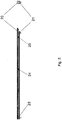
- FIGS. 1 and 2 Two different embodiments of the elastic suspension of the damper assembly 3 on the frame 1 of a sliding door system are shown schematically. Identical modules are provided with identical reference numerals. The representation according to the FIGS. 1 and 2 is purely schematic.
- Fig. 1 shows the suspension of a damper assembly 3 on the upper frame 1 of a sliding door assembly.
- the damper assembly 3 is mounted on a mounting system 2.
- the mounting system 2 is suspended by means of two springs 4, 5 resiliently on the frame 1.
- the damper assembly 3 is displaceable in total in a vertical upward direction on the frame by compression of the two springs 4, 5.
- damper assembly 3 by the spring suspension by means of the two springs 4, 5 perform any relative movements relative to the frame 1, ie that the damper assembly 3 is pivotable about arbitrary axes of rotation relative to the frame 1 by the two springs 4, 5 compressed to different degrees become.
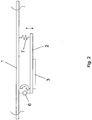
- Fig. 2 shows a second embodiment of the elastic suspension of the damper assembly 3 on the frame 1.
- the damper assembly 3 is fixedly mounted on the mounting system 2.
- the mounting system 2 is hinged at its left end to the frame 1.
- the joint 6 is provided.
- the right end of the mounting system 2 is shown in the illustration Fig. 2 spring elastically coupled to the frame 1 via the spring 7.
- the mounting system 2 with the damper assembly 3 mounted thereon can perform a relative movement with respect to the profile 1 by pivoting about the axis of rotation of the joint 6 around.
- FIG. 2 The representation according to Fig. 2 is in particular only insofar schematically as that an articulated suspension can also be provided at the right end of the mounting system 2 and a spring-elastic coupling via a spring on the left end of the mounting system 2.
- FIGS. 3 to 7 Another embodiment of the invention is in the FIGS. 3 to 7 shown, which will be explained below.
- identical components are each provided with identical reference numerals.
- Fig. 3 shows a perspective view of a sliding door system with the in the illustration according to Fig. 3 upwardly pulled out upper frame 10 and a lower frame 11.
- the lower frame 11 of the sliding door system has three parallel grooves, in each of which a sliding door member 12, 13, 14 in the image plane according to Fig. 3 is slidably disposed to the right and left along the lower frame 11 of the sliding door system.
- the sliding door elements 12, 13, 14 can thus be moved both completely to the right in the sliding door system as well as completely to the left in the sliding door system, so that the sliding door elements 12, 13, 14 form three successive sliding door elements in the form of a package, so that the rest Area of the sliding door system is fully open.
- the sliding door elements 12, 13, 14 are formed by glass elements.
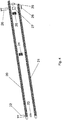
- the assembly of the damper assembly 30 to the upper frame 10 by means of in Fig. 4 in the form of an exploded view mounting system.
- the mounting system is formed by a mounting profile 20 which is fixed to the upper frame 10.
- the mounting profile 20 is inserted into a corresponding C-groove in the upper frame 10 of the Schleubtsystems and fixed at the desired position by means of a clamping screw. This allows a displacement of the mounting profile 20 in the C-groove along the upper frame 10 to take place to the desired position. Further, mounting of the mounting system to the upper frame 10 at any position is possible.
- the rail 21 On the mounting profile 20, the rail 21 is fixed.
- the rail 21 serves to receive the damper assembly 30. This will be discussed below with reference to FIG Fig. 7 explained.
- the rail 21 is fixedly connected at its left end by means of a blind rivet 22 with the mounting profile 20.
- the spacing between the rail 21 and the mounting profile 20 is ensured at the left end by the spacer sleeve 23, which defines the distance between the mounting rail 20 and rail 21 at the same time.
- the sliding bearing 27 is provided at its right end. This is penetrated by the blind rivet 26.
- the blind rivet 26 is mounted on the underside of the rail 21 with the disc 28 and fixed by this.
- two compression springs 24, 25 are provided. Due to the sliding bearing 27, a relative movement of the right end of the rail 21 relative to the mounting profile 20 is possible, which allows a pivoting movement about the defined by the spacer sleeve 23 left end of the mounting system.
- the compression springs 24, 25 are dimensioned such that their axial dimension corresponds to the height of the spacer sleeve 23 when the compression springs 24, 25 are pressed together in a block.
- FIG. 5 and 6 show the mounting system Fig. 4 in the assembled state, wherein in the illustration according to the Figures 5 and 6 the compression springs 24, 25 are completely compressed and the rail 21 thereby the minimally possible distance to the mounting profile 20 has taken.
- Fig. 5 shows the side view and the front view of the mounting system during Fig. 6 shows a perspective view of the mounting system for mounting the damper assembly to the frame of the sliding door system.
- Fig. 7 shows an exploded perspective view of the mounting system and the damper assembly 30.
- the damper assembly 30 is screwed by means of the fastening screws 33, 34 to the rail 21.
- the damper assembly 30 includes the damper 31 and the cam 32.
- the driver 32 protrudes into the travel path of that sliding door element 12, whose movement is intended to damp the damper arrangement 30 in the direction of the left end in the illustrated embodiment.
- the damper assembly 30 can perform a relative movement relative to the upper frame 10 of the sliding door system, so that any positional deviations can be compensated and it is always ensured that the driver 32 protrudes into the travel of that sliding door element 12 whose movement is to be damped in the direction of the end position of the sliding door element 12.
Landscapes
- Engineering & Computer Science (AREA)
- Mechanical Engineering (AREA)
- Wing Frames And Configurations (AREA)
Abstract
Description
- Die Erfindung betrifft ein Schiebetürsystem mit einem Rahmen, der mehrere Schiebetürelemente aufnimmt, welche horizontal entlang des Rahmens verfahrbar sind, wobei der Rahmen zumindest eine Dämpferanordnung aufweist, welche die Bewegung eines Schiebtürelementes in Richtung auf eine Endposition des Schiebetürelementes dämpft und begrenzt.
- Derartige Schiebetürsysteme sind bekannt.
- Nachteilig bei den bekannten Schiebetürsystemen ist es, dass bei einer Verformung des Rahmens beispielsweise unter einer Schneelast die daran angeordnete Dämpferanordnung ebenfalls aus der Ruheposition verlagert wird, wodurch es nicht mehr gewährleistet ist, dass die Dämpferanordnung bei Verfahren eines Schiebetürelementes wirksam wird.
- Die Aufgabe der Erfindung ist es, diese Nachteile zu überwinden und ein Schiebtürsystem mit einer zuverlässig arbeitenden Dämpferanordnung anzugeben.
- Diese Aufgabe wird erfindungsgemäß durch ein Schiebetürsystem gemäß Anspruch 1 gelöst. Vorteilhafte Weiterbildungen der Erfindung sind in den Unteransprüchen angegeben.
- Besonders vorteilhaft bei dem Schiebetürsystem mit einem Rahmen, der mehrere Schiebetürelemente aufnimmt, welche horizontal entlang des Rahmens verfahrbar sind, wobei der Rahmen zumindest eine Dämpferanordnung aufweist, welche die Bewegung eines Schiebtürelementes in Richtung auf eine Endposition des Schiebetürelementes dämpft und begrenzt, ist es, dass die Dämpferanordnung an dem Rahmen elastisch, insbesondere federelastisch gelagert ist.
- Dementsprechend ist die Dämpferanordnung gegenüber dem Rahmen relativ beweglich und insbesondere senkrecht zur Bewegungsrichtung des Schiebtürelementes relativ beweglich. Durch die elastische Lagerung der Dämpferanordnung an dem Rahmen wird somit Insbesondere eine Relativbewegung der Dämpferanordnung gegenüber dem Rahmen und insbesondere senkrecht zur Bewegungsrichtung des Schiebtürelementes entlang des Rahmens ermöglicht. Hierdurch kann ein Ausgleich von Durchbiegungen des Rahmens beispielsweise unter Schneelast oder dem Eigengewicht erfolgen, sodass ein Zusammenwirken von verfahrendem Schiebtürelement und der die Bewegung des Schiebtürelementes dämpfenden Dämpferanordnung zuverlässig gewährleistet ist.
- Vorzugsweise ist der Dämpfer an einer Schiene angeordnet, wobei ein erstes Ende der Schiene mittelbar oder unmittelbar gelenkig und/oder pendelnd und/oder federelastisch an dem Rahmen festgelegt und ein zweites Ende der Schiene mittelbar oder unmittelbar federelastisch mit dem Rahmen gekoppelt ist. Die Kopplung mit dem Rahmen kann somit mittelbar oder unmittelbar sowohl mittels eines oder mehrerer Gelenke und/oder mittels eines oder mehrerer Federelemente und/oder in Form einer pendelnden Aufgehängung erfolgen.
- Die Dämpferanordnung kann somit insbesondere mittels zweier oder mehrerer voneinander beabstandeter Federelemente mittelbar oder unmittelbar federelastisch mit dem Rahmen gekoppelt sein. Bei einer mittelbaren Kopplung können Zwischenelemente wie beispielsweise Verbindungs- und/oder Ausgleichs- und/oder Montageelemente angeordnet sein.
- Hierdurch ist eine Relativbewegung der Dämpferanordnung gegenüber dem Rahmen möglich. Ferner ist ein Drehen der Dämpferanordnung um eine beliebige Drehachse möglich, um Lageabweichungen auszugleichen und die Dämpferanordnung in eine Position zu verlagern, in welcher sie die Bewegung des Schiebtürelementes in Richtung auf dessen Endposition wirksam dämpft und begrenzt.
- Besonders bevorzugt weist die Dämpferanordnung einen Endanschlag zur Begrenzung des Bewegungsweges des Schiebtürelementes auf.
- Ferner kann die die Dämpferanordnung einen Mitnehmer aufweisen, der in den Fahrweg des Schiebetürolementes hineinragt und derart positioniert ist, um in Eingriff mit dem Schiebetürelement zu gelangen. Durch einen solchen Mitnehmer ist es gewährleistet, dass das Dämpferelement mit dem entlang des Rahmens verfahrenden Schiebtürelement in Eingriff kommt und die Dämpfungswirkung im Hinblick auf die Bewegung des Schiebtürelementes entfaltet.
- Vorzugsweise ist die Dämpferanordnung an einem oberen horizontalen Rahmenelement und/oder dass die Dämpferanordnung an einem unteren horizontalen Rahmenelement angeordnet.
- In einer bevorzugten Ausführungsform weist der Rahmen mehrere in Verfahrrichtung der Schiebtürelemente verlaufende parallel nebeneinander liegende Nuten auf, wobei in jeder Nut ein Schiebtürelement geführt ist. Durch die Anordnung mehrerer parallel verlaufender Nuten können mehrere Schiebtürelemente in dem Rahmen verfahrbar geführt werden.
- Vorzugsweise ist zu jedem der Schiebtürelemente eine korrespondierende Dämpferanordnung an dem Rahmen elastisch, insbesondere federelastisch angeordnet.
- Die Schiebetürelemente können hängend und/oder stehend in oder an dem Rahmen gelagert sein. Das bedeutet, dass die Lagerung der Schiebetürelemente sowohl an einem oberen Rahmenelement als auch kumulativ oder alternativ an einem unteren Rahmenelement erfolgen kann. Die Schiebetürelemente können oben und/oder unten Lager aufweisen, insbesondere Laufrollen und/oder Gleiter aufweisen, mittels derer sie in einer oberen Führungsschiene und/oder in einer unteren Führungsschiene des Rahmens verfahrbar gelagert sind. Dabei kann eine obere Führungsschiene an einem oberen insbesondere horizontalen Rahmenelement angeordnet oder durch ein oberes insbesondere horizontales Rahmenelement selbst gebildet sein. Eine untere Führungsschiene kann an einem unteren insbesondere horizontalen Rahmenelement angeordnet oder durch ein unteres Insbesondere horizontales Rahmenelement selbst gebildet sein.
- In einer bevorzugten Ausführungsform weisen die Schiebetürelemente eine Sicherung und/oder Verriegelung, insbesondere eine Stiftsicherung und/oder einen Schnapper gegen ungewolltes Öffnen auf. Hierdurch kann insbesondere ein unbefugtes Öffnen von Außen verhindert werden.
- Die Schiebetürelemente können als Glastüren, insbesondere als rahmenlose Glastüren, ausgebildet sein. Alternativ ist es auch möglich, dass andere Materialien, wie Aluminiumelemente oder dergleichen zum Einsatz kommen. Eine optisch besonders ansprechende Gesamtlösung ergibt sich Jedoch, wenn sämtliche Schiebetürelemente als Glastüren ausgebildet sind, da sich dann im geschlossenen Zustand eine über den gesamten Rahmen erstreckende Glaswand bildet.
- Sofern die Schiebetürelemente als Glastüren ausgebildet sind, sind diese vorzugsweise aus Sicherheitsglas und/oder Isolierglas gebildet. Bei einem Einsatz von Isolierglas können die erfindungsgemäßen Schiebetürsysteme auch im Warmbereich, d.h. beispielsweise bei beheizten Wintergärten oder als Wohnzimmerabschluss zur Terrasse hin eingesetzt werden. Der Einsatz der erfindungsgemäßen Schiebetürsysteme ist hierauf nicht beschränkt, da auch der Einsatz im Kaltbereich, also bei unbeheizten Wintergärten und dergleichen, möglich ist.
- Die Schiebetürelemente können in beliebigem Höhen-/Breitenverhältnis ausgebildet sein. Vorzugsweise ist jedoch das maximale Seitenverhältnis bei einem einzelnen Schiebetürelement von Höhe zu Breite gleich 5 zu 1.
- Verschiedene Ausführungsbeispiele des Schiebetürsystems sind in den Figuren dargestellt und werden nachfolgend näher erläutert. Es zeigen:
- Fig. 1
- Eine schematische Darstellung einer ersten Ausführungsform der Aufhängung einer Dämpferanordnung am Rahmen eines Schiebetürsystems;
- Fig. 2
- eine schematische Darstellung einer zweiten Ausführungsform der Aufhängung einer Dämpferanordnung am Rahmen eines Schiebetürsystems;
- Fig. 3
- eine perspektivische Ansicht eines Schiebetürsystems;
- Fig. 4
- eine Explosionsdarstellung des Montagesystems für die Montage der Dämpferanordnung am Rahmen des Schlebetürsystems nach
Fig. 3 ; - Fig. 5
- die Seitenansicht sowie die Vorderansicht des Montagesystems für die Montage der Dämpferanordnung am Rahmen des Schiebetürsystems nach
Fig. 4 ; - Fig. 6
- eine perspektivische Ansicht des Montagesystems für die Montage der Dämpferanordnung am Rahmen des Schiebetürsystems nach
Fig. 4 ; - Fig. 7
- eine perspektivische Explosionsdarstellung des Montagesystems sowie der Dämpferanordnung.
- In den
Figuren 1 und2 sind zwei verschiedene Ausführungsformen der elastischen Aufhängung der Dämpferanordnung 3 am Rahmen 1 eines Schiebetürsystems schematisch dargestellt. Identische Baugruppen sind dabei mit identischen Bezugszeichen versehen. Die Darstellung gemäß denFiguren 1 und2 ist rein schematisch. -
Fig. 1 zeigt die Aufhängung einer Dämpferanordnung 3 an dem oberen Rahmen 1 einer Schiebetüranordnung. Die Dämpferanordnung 3 ist montiert an einem Montagesystem 2. Das Montagesystem 2 ist mittels zweier Federn 4, 5 federelastisch an dem Rahmen 1 aufgehängt. Wie durch die beiden Doppelpfeile angedeutet kann durch die Aufhängung über die beiden Federn 4, 5 des Montagesystems 2 an dem Rahmen 1 die an dem Montagesystem 2 angeordnete Dämpferanordnung 3 beliebige Relativbewegungen gegenüber dem Rahmen 1 ausführen. Das bedeutet, dass die Dämpferanordnung 3 insgesamt in senkrechter Richtung nach oben auf dem Rahmen durch Kompression der beiden Federn 4, 5 verlagerbar ist. Ferner kann die Dämpferanordnung 3 durch die federnde Aufhängung mittels der beiden Federn 4, 5 beliebige Relativbewegungen gegenüber dem Rahmen 1 ausführen, d. h. dass die Dämpferanordnung 3 um beliebige Drehachsen herum gegenüber dem Rahmen 1 verschwenkbar ist, indem die beiden Federn 4, 5 unterschiedlich stark komprimiert werden. -
Fig. 2 zeigt ein zweites Ausführungsbeispiel der elastischen Aufhängung der Dämpferanordnung 3 an dem Rahmen 1. Wiederum ist die Dämpferanordnung 3 an dem Montagesystem 2 fest montiert. Das Montagesystem 2 ist an seinem linken Ende an dem Rahmen 1 gelenkig aufgehängt. Hierzu ist das Gelenk 6 vorgesehen. Das rechte Ende des Montagesystems 2 ist in der Darstellung gemäßFig. 2 über die Feder 7 federelastisch mit dem Rahmen 1 gekoppelt. Hierdurch vermag das Montagesystem 2 mit der daran montierten Dämpferanordnung 3 eine Relativbewegung gegenüber dem Profil 1 durch ein Verschwenken um die Drehachse des Gelenkes 6 herum auszuführen. - Die Darstellung gemäß
Fig. 2 ist insbesondere insofern nur schematisch, als dass eine gelenkige Aufhängung auch am rechten Ende des Montagesystems 2 und eine federelastische Kopplung über eine Feder auch am linken Ende des Montagesystems 2 vorgesehen sein kann. - Ein weiteres Ausführungsbeispiel der Erfindung ist in den
Figuren 3 bis 7 dargestellt, weiches nachfolgend erläutert wird. Dabei sind identische Bauteile jeweils mit identischen Bezugszeichen versehen. -
Fig. 3 zeigt eine perspektivische Ansicht eines Schiebetürsystems mit dem in der Darstellung gemäßFig. 3 nach oben herausgezogenen oberen Rahmen 10 und einem unteren Rahmen 11. Der untere Rahmen 11 des Schiebetürsystems weist drei parallel angeordnete Nuten auf, in denen jeweils ein Schiebetürelement 12, 13, 14 in der Bildebene gemäßFig. 3 nach rechts und links entlang des unteren Rahmens 11 des Schiebetürsystems verschiebbar angeordnet ist. Die Schiebetürelemente 12, 13, 14 können somit sowohl vollständig nach rechts in dem Schiebetürsystem als auch vollständig nach links in dem Schiebetürsystem verschoben werden, so dass die Schiebetürelemente 12, 13, 14 drei hintereinander liegende Schiebetürelemente in Form eines Paketes bilden, so dass der übrige Bereich des Schiebetürsystems vollständig geöffnet ist. In dem dargestellten Ausführungsbeispiel sind die Schiebetürelemente 12, 13, 14 durch Glaselemente gebildet. - Am oberen Rahmen 10 ist die Positionierung der Dämpferanordnung 30 angedeutet. Die Montage der Dämpferanordnung 30 an dem oberen Rahmen 10 erfolgt mittels des in
Fig. 4 in Form einer Explosionsdarstellung dargestellten Montagesystems. Das Montagesystem ist gebildet durch ein Montageprofil 20, welches am dem oberen Rahmen 10 festgelegt wird. Hierzu wird das Montageprofil 20 in eine entsprechende C-Nut in dem oberen Rahmen 10 des Schlebetürsystems eingeschoben und an der gewünschten Position mittels einer Klemmschraube festgelegt. Hierdurch kann ein Verschieben des Montageprofils 20 in der C-Nut entlang des oberen Rahmens 10 bis an die gewünschte Position erfolgen. Ferner ist eine Montage des Montagesystems an dem oberen Rahmen 10 an einer beliebigen Position möglich. - An dem Montageprofil 20 ist die Schiene 21 festgelegt. Die Schiene 21 dient der Aufnahme der Dämpferanordnung 30. Dies wird weiter unten in Bezug auf
Fig. 7 erläutert. - Die Schiene 21 ist an ihrem linken Ende mittels einer Blindniete 22 mit dem Montageprofil 20 fest verbunden. Die Beabstandung zwischen der Schiene 21 und dem Montageprofil 20 wird am linken Ende durch die Distanzhülse 23 gewährleistet, die gleichzeitig den Abstand zwischen Montageprofil 20 und Schiene 21 definiert. An ihrem rechten Ende ist das Gleitlager 27 vorgesehen. Dieses wird durchgriffen von der Blindniete 26. Die Blindniete 26 wird an der Unterseite der Schiene 21 mit der Scheibe 28 montiert und von dieser fixiert.
- Ferner sind zwei Druckfedern 24, 25 vorgesehen. Aufgrund des Gleitlagers 27 ist eine Relativbewegung des rechten Endes der Schiene 21 gegenüber dem Montageprofil 20 möglich, was einer Schwenkbewegung um das durch die Distanzhülse 23 definierte linke Ende des Montagesystems ermöglicht. Die Druckfedern 24, 25 sind derart dimensioniert, dass ihr Axialmaß der Höhe der Distanzhülse 23 entspricht, wenn die Druckfedern 24, 25 auf Block zusammengepresst werden.
- Auf Grund der Anordnung des Gleitlagers 27 und der Druckfedern 24, 25 ist es somit möglich, dass die Schiene 21 elastisch eine Relativbewegung gegenüber dem Montageprofil 20 ausführt.
- Die Festlegung des Montagesystems an der gewünschten Position an dem oberen Rahmen 10 des Schlebetürsystems erfolgt mittels des Gewindestiftes 29, der eine Gewindebohrung in dem Montageprofil 20 durchgreift und mittels dessen das Montagesystem an der gewünschten Stelle in der C-Nut an dem oberen Rahmen 10 durch Klemmung festgelegt wird.
- Die
Figuren 5 und6 zeigen das Montagesystem nachFig. 4 in montiertem Zustand, wobei in der Darstellung gemäß denFiguren 5 und6 die Druckfedern 24, 25 vollständig zusammengepresst sind und die Schiene 21 hierdurch den minimal möglichen Abstand zum Montageprofil 20 eingenommen hat.Fig. 5 zeigt die Seitenansicht sowie die Vorderansicht des Montagesystems währendFig. 6 eine perspektivische Ansicht des Montagesystems für die Montage der Dämpferanordnung an dem Rahmen des Schiebetürsystems zeigt. -
Fig. 7 zeigt eine perspektivische Explosionsdarstellung des Montagesystems sowie der Dämpferanordnung 30. Die Dämpferanordnung 30 wird mittels der Befestigungsschrauben 33, 34 an der Schiene 21 angeschraubt. Die Dämpferanordnung 30 weist den Dämpfer 31 und den Mitnehmer 32 auf. Der Mitnehmer 32 ragt in den Verfahrweg desjenigen Schiebetürelementes 12 ein, dessen Bewegung die Dämpferanordnung 30 in Richtung auf das linke Ende in dem dargestellten Ausführungsbeispiel dämpfen soll. Durch die elastische Anordnung der Schiene 21 gegenüber dem Montageprofil 20 vermag die Dämpferanordnung 30 eine Relativbewegung gegenüber dem oberen Rahmen 10 des Schiebetürsystems auszuführen, so dass etwaige Lageabweichungen ausgeglichen werden können und es stets gewährleistet ist, dass der Mitnehmer 32 in den Verfahrweg desjenigen Schiebetürelementes 12 hineinragt, dessen Bewegung in Richtung auf die Endposition des Schiebetürelementes 12 gedämpft werden soll.
Claims (11)
- Schiebetürsystem mit einem Rahmen (10, 11), der mehrere Schiebetürelemente (12, 13, 14) aufnimmt, welche horizontal entlang des Rahmens (10, 11) verfahrbar sind, wobei der Rahmen (10, 11) zumindest eine Dämpferanordnung (30) aufweist, welche die Bewegung eines Schiebtürelementes (12, 13, 14) in Richtung auf eine Endposition des Schiebetürelementes (12, 13, 14) dämpft und begrenzt, dadurch gekennzeichnet, dass die Dämpferanordnung (30) an dem Rahmen (10, 11) elastisch, insbesondere federelastisch gelagert ist.
- Schiebetürsystem nach Anspruch 1, dadurch gekennzeichnet, dass die Dämpferanordnung (30) an einer Schiene (21) angeordnet ist, wobei ein erstes Ende der Schiene (21) mittelbar oder unmittelbar gelenkig und/oder pendelnd und/oder federelastisch an dem Rahmen (10, 11) festgelegt und ein zweites Ende der Schiene (21) mittelbar oder unmittelbar federelastisch mit dem Rahmen (10) gekoppelt ist.
- Schiebetürsystem nach Anspruch 1 oder 2, dadurch gekennzeichnet, dass die Dämpferanordnung (30) einen Endanschlag zur Begrenzung des Bewegungsweges des Schiebtürelementes (12, 13, 14) aufweist.
- Schiebetürsystem nach einem der vorherigen Ansprüche, dadurch gekennzeichnet, dass die Dämpferanordnung (30) einen Mitnehmer (32) aufweist, der in den Fahrweg des Schiebetürelementes (12, 13, 14) hineinragt und derart positioniert ist, um in Eingriff mit dem Schiebetürelement (12, 13, 14) zu gelangen.
- Schiebetürsystem nach einem der vorherigen Ansprüche, dadurch gekennzeichnet, dass die Dämpferanordnung (30) an einem oberen horizontalen Rahmenelement (10) und/oder dass die Dämpferanordnung (30) an einem unteren horizontalen Rahmenelement (11) angeordnet ist.
- Schiebetürsystem nach einem der vorherigen Ansprüche, dadurch gekennzeichnet, dass der Rahmen (10, 11) mehrere in Verfahrrichtung der Schiebtürelemente (12, 13, 14) verlaufende parallel nebeneinander liegende Nuten aufweist, wobei in jeder Nut ein Schiebtürelement (12, 13, 14) geführt ist.
- Schiebetürsystem nach einem der vorherigen Ansprüche, dadurch gekennzeichnet, dass zu jedem der Schiebtürelemente (12, 13, 14) eine korrespondierende Dämpferanordnung (30) an dem Rahmen (10, 11) elastisch, insbesondere federelastisch angeordnet ist.
- Schiebetürsystem nach einem der vorherigen Ansprüche, dadurch gekennzeichnet, dass die Schiebetürelemente (12, 13, 14) hängend und/oder stehend in oder an dem Rahmen (10, 11) gelagert sind.
- Schiebetürsystem nach einem der vorherigen Ansprüche, dadurch gekennzeichnet, dass die Schiebetürelemente (12, 13, 14) oben und/oder unten Lager aufweisen, insbesondere Laufrollen und/oder Gleiter aufweisen, mittels derer sie in einer oberen Führungsschiene und/oder in einer unteren Führungsschiene des Rahmens (10, 11) verfahrbar gelagert sind.
- Schiebetürsystem nach einem der vorherigen Ansprüche, dadurch gekennzeichnet, dass die Schiebetürelemente (12, 13, 14) eine Sicherung und/oder Verriegelung, insbesondere eine Stiftsicherung und/oder einen Schnapper gegen ungewolltes Öffnen aufweisen.
- Schiebetürsystem nach einem der vorherigen Ansprüche, dadurch gekennzeichnet, dass die Schiebetürelemente (12, 13, 14) als Glastüren, insbesondere als rahmenlose Glastüren, ausgebildet sind.
Applications Claiming Priority (1)
| Application Number | Priority Date | Filing Date | Title |
|---|---|---|---|
| DE102016006101.4A DE102016006101A1 (de) | 2016-05-20 | 2016-05-20 | Schiebetürsystem mit Dämpferanordnung |
Publications (2)
| Publication Number | Publication Date |
|---|---|
| EP3246500A1 true EP3246500A1 (de) | 2017-11-22 |
| EP3246500B1 EP3246500B1 (de) | 2021-03-17 |
Family
ID=58544681
Family Applications (1)
| Application Number | Title | Priority Date | Filing Date |
|---|---|---|---|
| EP17000580.5A Active EP3246500B1 (de) | 2016-05-20 | 2017-04-06 | Schiebetürsystem mit dämpferanordnung |
Country Status (2)
| Country | Link |
|---|---|
| EP (1) | EP3246500B1 (de) |
| DE (1) | DE102016006101A1 (de) |
Families Citing this family (1)
| Publication number | Priority date | Publication date | Assignee | Title |
|---|---|---|---|---|
| KR102592617B1 (ko) * | 2018-02-13 | 2023-10-23 | 테르노 스코레볼리 에스.피.에이. 유니페르소날레 | 문과 옷장 문을 슬라이딩으로 움직이기 위한 장치 |
Citations (5)
| Publication number | Priority date | Publication date | Assignee | Title |
|---|---|---|---|---|
| US3152354A (en) * | 1960-11-21 | 1964-10-13 | Arthur G Diack | Adjustable framing assembly |
| WO2008028945A2 (en) * | 2006-09-06 | 2008-03-13 | Liexco S.A. | Modular rail system for suspending sliding doors and sliding door system with user accessible braking / stopping element |
| DE202010001367U1 (de) * | 2010-01-25 | 2010-04-15 | FOUNDER ALUMINIUM CO., LTD., Lugang | Selbstrückstellende Schienenanordnung für einen Schrank |
| DE202009000616U1 (de) * | 2009-01-15 | 2010-05-27 | Hettich-Heinze Gmbh & Co. Kg | Schiebetürbeschlag für zweiflügelige Schiebetür |
| EP2899350A1 (de) * | 2014-01-23 | 2015-07-29 | Koblenz S.P.A. | Anhalte- und Dämpfungsvorrichtung für Transporteinheiten von Schiebetüren von Gebäuden oder Möbeln und dergleichen |
Family Cites Families (4)
| Publication number | Priority date | Publication date | Assignee | Title |
|---|---|---|---|---|
| DE20018838U1 (de) * | 2000-11-04 | 2001-02-08 | Hettich-Heinze GmbH & Co. KG, 32139 Spenge | Verstellbare Stopp- und Dämpfungsvorrichtung für Schiebe- und/oder Faltschiebetürelemente |
| ATE393282T1 (de) * | 2005-02-25 | 2008-05-15 | Calvo Miguel Angel Rioja | Lagervorrichtung und verriegelungseinrichtung für schiebetüre eines kleiderschrankes |
| DE202008012990U1 (de) * | 2008-09-30 | 2008-12-04 | Bortoluzzi Mobili S.R.L. | Vorrichtung zum Dämpfen einer Öffnungs- und Schließbewegung von Rollläden, insbesondere für Möbel |
| KR20130114504A (ko) * | 2012-04-09 | 2013-10-17 | 안중식 | 슬라이드 도어 완충장치 |
-
2016
- 2016-05-20 DE DE102016006101.4A patent/DE102016006101A1/de not_active Withdrawn
-
2017
- 2017-04-06 EP EP17000580.5A patent/EP3246500B1/de active Active
Patent Citations (5)
| Publication number | Priority date | Publication date | Assignee | Title |
|---|---|---|---|---|
| US3152354A (en) * | 1960-11-21 | 1964-10-13 | Arthur G Diack | Adjustable framing assembly |
| WO2008028945A2 (en) * | 2006-09-06 | 2008-03-13 | Liexco S.A. | Modular rail system for suspending sliding doors and sliding door system with user accessible braking / stopping element |
| DE202009000616U1 (de) * | 2009-01-15 | 2010-05-27 | Hettich-Heinze Gmbh & Co. Kg | Schiebetürbeschlag für zweiflügelige Schiebetür |
| DE202010001367U1 (de) * | 2010-01-25 | 2010-04-15 | FOUNDER ALUMINIUM CO., LTD., Lugang | Selbstrückstellende Schienenanordnung für einen Schrank |
| EP2899350A1 (de) * | 2014-01-23 | 2015-07-29 | Koblenz S.P.A. | Anhalte- und Dämpfungsvorrichtung für Transporteinheiten von Schiebetüren von Gebäuden oder Möbeln und dergleichen |
Also Published As
| Publication number | Publication date |
|---|---|
| EP3246500B1 (de) | 2021-03-17 |
| DE102016006101A1 (de) | 2017-11-23 |
Similar Documents
| Publication | Publication Date | Title |
|---|---|---|
| EP3880922B1 (de) | Führungssystem zur führung eines bewegbar gelagerten türflügels | |
| EP3943700A1 (de) | Führungssystem zur führung eines türflügels | |
| DE102020108110B3 (de) | Türband und Verfahren zu dessen Montage | |
| DE2648344A1 (de) | Beschlag fuer schiebefenster, schiebetueren u.dgl. | |
| EP3034734B1 (de) | Band für eine tür oder ein fenster | |
| EP3168398B1 (de) | Verstecktes scharnier für türen, fenster oder ähnliche bauteile | |
| EP4077850B1 (de) | Führungssystem zur führung eines bewegbar gelagerten türflügels | |
| AT524557B1 (de) | Führungssystem zur Führung wenigstens eines Türflügels relativ zu einem Möbelkorpus | |
| AT523303B1 (de) | Führungsvorrichtung zur Führung eines Möbelteils | |
| EP3045634B1 (de) | Ausstellvorrichtung für ein fenster oder eine tür mit einer energiespeichereinrichtung | |
| EP3880916B1 (de) | Führungssystem zur führung zumindest eines bewegbar gelagerten möbelteiles | |
| EP2503084B1 (de) | Verstellbares Scharnierband | |
| EP3246500B1 (de) | Schiebetürsystem mit dämpferanordnung | |
| DE102019211796B4 (de) | Führungsbeschlag für eine Schiebeflügelanordnung und Schiebeflügelanordnung | |
| EP3922798A1 (de) | Tür mit einem scharnier mit integrierter anschlagdämpfung | |
| DE19650085C2 (de) | Unteres Ecklager für ein Kipp-Schwenkfenster, eine Kipp-Schwenktür oder dergleichen | |
| EP3786405B1 (de) | Möbelantrieb zum bewegen eines bewegbar gelagerten möbelteiles | |
| EP3029227B2 (de) | Beschlag mit einstellbarem Einspannbereich | |
| EP1614844A2 (de) | Drehlagervorrichtung | |
| DE102018100550A1 (de) | Führungsgleiter für ein schiebetür- und/oder schiebefenstersystem, beweglicher schieberahmen mit einem führungsgleiter sowie schiebetür- und/oder schiebefenstersystem mit führungsleiter | |
| DE102014202797B3 (de) | Distanzhalter | |
| EP3736390B1 (de) | Lamellendach mit reibelement | |
| WO2021119690A1 (de) | Verbindungsvorrichtung, insbesondere scharnier | |
| EP1067264A1 (de) | Treibstangenbeschlag-System und Stulpeneinsatzkörper hierfür | |
| DE202022103033U1 (de) | Schiebetür Dämpferanbindung |
Legal Events
| Date | Code | Title | Description |
|---|---|---|---|
| PUAI | Public reference made under article 153(3) epc to a published international application that has entered the european phase |
Free format text: ORIGINAL CODE: 0009012 |
|
| STAA | Information on the status of an ep patent application or granted ep patent |
Free format text: STATUS: THE APPLICATION HAS BEEN PUBLISHED |
|
| AK | Designated contracting states |
Kind code of ref document: A1 Designated state(s): AL AT BE BG CH CY CZ DE DK EE ES FI FR GB GR HR HU IE IS IT LI LT LU LV MC MK MT NL NO PL PT RO RS SE SI SK SM TR |
|
| AX | Request for extension of the european patent |
Extension state: BA ME |
|
| STAA | Information on the status of an ep patent application or granted ep patent |
Free format text: STATUS: REQUEST FOR EXAMINATION WAS MADE |
|
| 17P | Request for examination filed |
Effective date: 20180517 |
|
| RBV | Designated contracting states (corrected) |
Designated state(s): AL AT BE BG CH CY CZ DE DK EE ES FI FR GB GR HR HU IE IS IT LI LT LU LV MC MK MT NL NO PL PT RO RS SE SI SK SM TR |
|
| STAA | Information on the status of an ep patent application or granted ep patent |
Free format text: STATUS: EXAMINATION IS IN PROGRESS |
|
| 17Q | First examination report despatched |
Effective date: 20180928 |
|
| GRAP | Despatch of communication of intention to grant a patent |
Free format text: ORIGINAL CODE: EPIDOSNIGR1 |
|
| STAA | Information on the status of an ep patent application or granted ep patent |
Free format text: STATUS: GRANT OF PATENT IS INTENDED |
|
| RIC1 | Information provided on ipc code assigned before grant |
Ipc: E05F 5/00 20170101ALI20201020BHEP Ipc: E05D 15/08 20060101ALN20201020BHEP Ipc: E05D 15/06 20060101AFI20201020BHEP |
|
| INTG | Intention to grant announced |
Effective date: 20201113 |
|
| GRAS | Grant fee paid |
Free format text: ORIGINAL CODE: EPIDOSNIGR3 |
|
| GRAA | (expected) grant |
Free format text: ORIGINAL CODE: 0009210 |
|
| STAA | Information on the status of an ep patent application or granted ep patent |
Free format text: STATUS: THE PATENT HAS BEEN GRANTED |
|
| AK | Designated contracting states |
Kind code of ref document: B1 Designated state(s): AL AT BE BG CH CY CZ DE DK EE ES FI FR GB GR HR HU IE IS IT LI LT LU LV MC MK MT NL NO PL PT RO RS SE SI SK SM TR |
|
| REG | Reference to a national code |
Ref country code: GB Ref legal event code: FG4D Free format text: NOT ENGLISH |
|
| REG | Reference to a national code |
Ref country code: CH Ref legal event code: EP |
|
| REG | Reference to a national code |
Ref country code: DE Ref legal event code: R096 Ref document number: 502017009708 Country of ref document: DE |
|
| REG | Reference to a national code |
Ref country code: IE Ref legal event code: FG4D Free format text: LANGUAGE OF EP DOCUMENT: GERMAN |
|
| REG | Reference to a national code |
Ref country code: AT Ref legal event code: REF Ref document number: 1372389 Country of ref document: AT Kind code of ref document: T Effective date: 20210415 |
|
| REG | Reference to a national code |
Ref country code: NL Ref legal event code: FP |
|
| REG | Reference to a national code |
Ref country code: LT Ref legal event code: MG9D |
|
| PG25 | Lapsed in a contracting state [announced via postgrant information from national office to epo] |
Ref country code: NO Free format text: LAPSE BECAUSE OF FAILURE TO SUBMIT A TRANSLATION OF THE DESCRIPTION OR TO PAY THE FEE WITHIN THE PRESCRIBED TIME-LIMIT Effective date: 20210617 Ref country code: HR Free format text: LAPSE BECAUSE OF FAILURE TO SUBMIT A TRANSLATION OF THE DESCRIPTION OR TO PAY THE FEE WITHIN THE PRESCRIBED TIME-LIMIT Effective date: 20210317 Ref country code: GR Free format text: LAPSE BECAUSE OF FAILURE TO SUBMIT A TRANSLATION OF THE DESCRIPTION OR TO PAY THE FEE WITHIN THE PRESCRIBED TIME-LIMIT Effective date: 20210618 Ref country code: FI Free format text: LAPSE BECAUSE OF FAILURE TO SUBMIT A TRANSLATION OF THE DESCRIPTION OR TO PAY THE FEE WITHIN THE PRESCRIBED TIME-LIMIT Effective date: 20210317 Ref country code: BG Free format text: LAPSE BECAUSE OF FAILURE TO SUBMIT A TRANSLATION OF THE DESCRIPTION OR TO PAY THE FEE WITHIN THE PRESCRIBED TIME-LIMIT Effective date: 20210617 |
|
| PG25 | Lapsed in a contracting state [announced via postgrant information from national office to epo] |
Ref country code: LV Free format text: LAPSE BECAUSE OF FAILURE TO SUBMIT A TRANSLATION OF THE DESCRIPTION OR TO PAY THE FEE WITHIN THE PRESCRIBED TIME-LIMIT Effective date: 20210317 Ref country code: RS Free format text: LAPSE BECAUSE OF FAILURE TO SUBMIT A TRANSLATION OF THE DESCRIPTION OR TO PAY THE FEE WITHIN THE PRESCRIBED TIME-LIMIT Effective date: 20210317 Ref country code: SE Free format text: LAPSE BECAUSE OF FAILURE TO SUBMIT A TRANSLATION OF THE DESCRIPTION OR TO PAY THE FEE WITHIN THE PRESCRIBED TIME-LIMIT Effective date: 20210317 |
|
| PG25 | Lapsed in a contracting state [announced via postgrant information from national office to epo] |
Ref country code: SM Free format text: LAPSE BECAUSE OF FAILURE TO SUBMIT A TRANSLATION OF THE DESCRIPTION OR TO PAY THE FEE WITHIN THE PRESCRIBED TIME-LIMIT Effective date: 20210317 Ref country code: CZ Free format text: LAPSE BECAUSE OF FAILURE TO SUBMIT A TRANSLATION OF THE DESCRIPTION OR TO PAY THE FEE WITHIN THE PRESCRIBED TIME-LIMIT Effective date: 20210317 Ref country code: EE Free format text: LAPSE BECAUSE OF FAILURE TO SUBMIT A TRANSLATION OF THE DESCRIPTION OR TO PAY THE FEE WITHIN THE PRESCRIBED TIME-LIMIT Effective date: 20210317 Ref country code: LT Free format text: LAPSE BECAUSE OF FAILURE TO SUBMIT A TRANSLATION OF THE DESCRIPTION OR TO PAY THE FEE WITHIN THE PRESCRIBED TIME-LIMIT Effective date: 20210317 |
|
| PG25 | Lapsed in a contracting state [announced via postgrant information from national office to epo] |
Ref country code: IS Free format text: LAPSE BECAUSE OF FAILURE TO SUBMIT A TRANSLATION OF THE DESCRIPTION OR TO PAY THE FEE WITHIN THE PRESCRIBED TIME-LIMIT Effective date: 20210717 Ref country code: RO Free format text: LAPSE BECAUSE OF FAILURE TO SUBMIT A TRANSLATION OF THE DESCRIPTION OR TO PAY THE FEE WITHIN THE PRESCRIBED TIME-LIMIT Effective date: 20210317 Ref country code: SK Free format text: LAPSE BECAUSE OF FAILURE TO SUBMIT A TRANSLATION OF THE DESCRIPTION OR TO PAY THE FEE WITHIN THE PRESCRIBED TIME-LIMIT Effective date: 20210317 Ref country code: PL Free format text: LAPSE BECAUSE OF FAILURE TO SUBMIT A TRANSLATION OF THE DESCRIPTION OR TO PAY THE FEE WITHIN THE PRESCRIBED TIME-LIMIT Effective date: 20210317 Ref country code: PT Free format text: LAPSE BECAUSE OF FAILURE TO SUBMIT A TRANSLATION OF THE DESCRIPTION OR TO PAY THE FEE WITHIN THE PRESCRIBED TIME-LIMIT Effective date: 20210719 |
|
| REG | Reference to a national code |
Ref country code: DE Ref legal event code: R097 Ref document number: 502017009708 Country of ref document: DE |
|
| PG25 | Lapsed in a contracting state [announced via postgrant information from national office to epo] |
Ref country code: LU Free format text: LAPSE BECAUSE OF NON-PAYMENT OF DUE FEES Effective date: 20210406 |
|
| PLBE | No opposition filed within time limit |
Free format text: ORIGINAL CODE: 0009261 |
|
| STAA | Information on the status of an ep patent application or granted ep patent |
Free format text: STATUS: NO OPPOSITION FILED WITHIN TIME LIMIT |
|
| PG25 | Lapsed in a contracting state [announced via postgrant information from national office to epo] |
Ref country code: ES Free format text: LAPSE BECAUSE OF FAILURE TO SUBMIT A TRANSLATION OF THE DESCRIPTION OR TO PAY THE FEE WITHIN THE PRESCRIBED TIME-LIMIT Effective date: 20210317 Ref country code: MC Free format text: LAPSE BECAUSE OF FAILURE TO SUBMIT A TRANSLATION OF THE DESCRIPTION OR TO PAY THE FEE WITHIN THE PRESCRIBED TIME-LIMIT Effective date: 20210317 Ref country code: DK Free format text: LAPSE BECAUSE OF FAILURE TO SUBMIT A TRANSLATION OF THE DESCRIPTION OR TO PAY THE FEE WITHIN THE PRESCRIBED TIME-LIMIT Effective date: 20210317 Ref country code: AL Free format text: LAPSE BECAUSE OF FAILURE TO SUBMIT A TRANSLATION OF THE DESCRIPTION OR TO PAY THE FEE WITHIN THE PRESCRIBED TIME-LIMIT Effective date: 20210317 |
|
| 26N | No opposition filed |
Effective date: 20211220 |
|
| PG25 | Lapsed in a contracting state [announced via postgrant information from national office to epo] |
Ref country code: SI Free format text: LAPSE BECAUSE OF FAILURE TO SUBMIT A TRANSLATION OF THE DESCRIPTION OR TO PAY THE FEE WITHIN THE PRESCRIBED TIME-LIMIT Effective date: 20210317 |
|
| PG25 | Lapsed in a contracting state [announced via postgrant information from national office to epo] |
Ref country code: IE Free format text: LAPSE BECAUSE OF NON-PAYMENT OF DUE FEES Effective date: 20210406 |
|
| PG25 | Lapsed in a contracting state [announced via postgrant information from national office to epo] |
Ref country code: IS Free format text: LAPSE BECAUSE OF FAILURE TO SUBMIT A TRANSLATION OF THE DESCRIPTION OR TO PAY THE FEE WITHIN THE PRESCRIBED TIME-LIMIT Effective date: 20210717 |
|
| PG25 | Lapsed in a contracting state [announced via postgrant information from national office to epo] |
Ref country code: HU Free format text: LAPSE BECAUSE OF FAILURE TO SUBMIT A TRANSLATION OF THE DESCRIPTION OR TO PAY THE FEE WITHIN THE PRESCRIBED TIME-LIMIT; INVALID AB INITIO Effective date: 20170406 |
|
| REG | Reference to a national code |
Ref country code: DE Ref legal event code: R082 Ref document number: 502017009708 Country of ref document: DE Representative=s name: KUTZENBERGER WOLFF & PARTNER PATENTANWALTSPART, DE Ref country code: DE Ref legal event code: R082 Ref document number: 502017009708 Country of ref document: DE Representative=s name: METHLING, FRANK-OLIVER, DIPL.-ING. DR.-ING., DE Ref country code: DE Ref legal event code: R082 Ref document number: 502017009708 Country of ref document: DE Representative=s name: PATENTANWALTSKANZLEI METHLING DR. FRANK-OLIVER, DE |
|
| PG25 | Lapsed in a contracting state [announced via postgrant information from national office to epo] |
Ref country code: CY Free format text: LAPSE BECAUSE OF FAILURE TO SUBMIT A TRANSLATION OF THE DESCRIPTION OR TO PAY THE FEE WITHIN THE PRESCRIBED TIME-LIMIT Effective date: 20210317 |
|
| PGFP | Annual fee paid to national office [announced via postgrant information from national office to epo] |
Ref country code: NL Payment date: 20230417 Year of fee payment: 7 |
|
| PGFP | Annual fee paid to national office [announced via postgrant information from national office to epo] |
Ref country code: IT Payment date: 20230428 Year of fee payment: 7 Ref country code: FR Payment date: 20230417 Year of fee payment: 7 Ref country code: CH Payment date: 20230502 Year of fee payment: 7 |
|
| PGFP | Annual fee paid to national office [announced via postgrant information from national office to epo] |
Ref country code: AT Payment date: 20230414 Year of fee payment: 7 |
|
| PGFP | Annual fee paid to national office [announced via postgrant information from national office to epo] |
Ref country code: BE Payment date: 20230417 Year of fee payment: 7 |
|
| PGFP | Annual fee paid to national office [announced via postgrant information from national office to epo] |
Ref country code: GB Payment date: 20230420 Year of fee payment: 7 |
|
| PG25 | Lapsed in a contracting state [announced via postgrant information from national office to epo] |
Ref country code: MK Free format text: LAPSE BECAUSE OF FAILURE TO SUBMIT A TRANSLATION OF THE DESCRIPTION OR TO PAY THE FEE WITHIN THE PRESCRIBED TIME-LIMIT Effective date: 20210317 |
|
| PG25 | Lapsed in a contracting state [announced via postgrant information from national office to epo] |
Ref country code: TR Free format text: LAPSE BECAUSE OF FAILURE TO SUBMIT A TRANSLATION OF THE DESCRIPTION OR TO PAY THE FEE WITHIN THE PRESCRIBED TIME-LIMIT Effective date: 20210317 |
|
| PG25 | Lapsed in a contracting state [announced via postgrant information from national office to epo] |
Ref country code: MT Free format text: LAPSE BECAUSE OF FAILURE TO SUBMIT A TRANSLATION OF THE DESCRIPTION OR TO PAY THE FEE WITHIN THE PRESCRIBED TIME-LIMIT Effective date: 20210317 |
|
| REG | Reference to a national code |
Ref country code: CH Ref legal event code: PL |
|
| REG | Reference to a national code |
Ref country code: NL Ref legal event code: MM Effective date: 20240501 |
|
| REG | Reference to a national code |
Ref country code: AT Ref legal event code: MM01 Ref document number: 1372389 Country of ref document: AT Kind code of ref document: T Effective date: 20240406 |
|
| GBPC | Gb: european patent ceased through non-payment of renewal fee |
Effective date: 20240406 |
|
| REG | Reference to a national code |
Ref country code: BE Ref legal event code: MM Effective date: 20240430 |
|
| PG25 | Lapsed in a contracting state [announced via postgrant information from national office to epo] |
Ref country code: BE Free format text: LAPSE BECAUSE OF NON-PAYMENT OF DUE FEES Effective date: 20240430 Ref country code: NL Free format text: LAPSE BECAUSE OF NON-PAYMENT OF DUE FEES Effective date: 20240501 |
|
| PG25 | Lapsed in a contracting state [announced via postgrant information from national office to epo] |
Ref country code: GB Free format text: LAPSE BECAUSE OF NON-PAYMENT OF DUE FEES Effective date: 20240406 |
|
| PG25 | Lapsed in a contracting state [announced via postgrant information from national office to epo] |
Ref country code: FR Free format text: LAPSE BECAUSE OF NON-PAYMENT OF DUE FEES Effective date: 20240430 |
|
| PG25 | Lapsed in a contracting state [announced via postgrant information from national office to epo] |
Ref country code: AT Free format text: LAPSE BECAUSE OF NON-PAYMENT OF DUE FEES Effective date: 20240406 |
|
| PG25 | Lapsed in a contracting state [announced via postgrant information from national office to epo] |
Ref country code: NL Free format text: LAPSE BECAUSE OF NON-PAYMENT OF DUE FEES Effective date: 20240501 Ref country code: GB Free format text: LAPSE BECAUSE OF NON-PAYMENT OF DUE FEES Effective date: 20240406 Ref country code: FR Free format text: LAPSE BECAUSE OF NON-PAYMENT OF DUE FEES Effective date: 20240430 Ref country code: BE Free format text: LAPSE BECAUSE OF NON-PAYMENT OF DUE FEES Effective date: 20240430 Ref country code: AT Free format text: LAPSE BECAUSE OF NON-PAYMENT OF DUE FEES Effective date: 20240406 Ref country code: CH Free format text: LAPSE BECAUSE OF NON-PAYMENT OF DUE FEES Effective date: 20240430 |
|
| REG | Reference to a national code |
Ref country code: DE Ref legal event code: R082 Ref document number: 502017009708 Country of ref document: DE Representative=s name: KUTZENBERGER WOLFF & PARTNER PATENTANWALTSPART, DE Ref country code: DE Ref legal event code: R082 Ref document number: 502017009708 Country of ref document: DE Representative=s name: METHLING, FRANK-OLIVER, DIPL.-ING. DR.-ING., DE Ref legal event code: R082 |
|
| PG25 | Lapsed in a contracting state [announced via postgrant information from national office to epo] |
Ref country code: IT Free format text: LAPSE BECAUSE OF NON-PAYMENT OF DUE FEES Effective date: 20240406 |
|
| REG | Reference to a national code |
Ref country code: DE Ref legal event code: R082 Ref document number: 502017009708 Country of ref document: DE Representative=s name: KUTZENBERGER WOLFF & PARTNER PATENTANWALTSPART, DE Ref country code: DE Ref legal event code: R082 Ref document number: 502017009708 Country of ref document: DE |
|
| REG | Reference to a national code |
Ref country code: DE Ref legal event code: R082 Ref document number: 502017009708 Country of ref document: DE Representative=s name: KUTZENBERGER WOLFF & PARTNER PATENTANWALTSPART, DE |
|
| PGFP | Annual fee paid to national office [announced via postgrant information from national office to epo] |
Ref country code: DE Payment date: 20250430 Year of fee payment: 9 |