EP3246504A2 - System zur überwachung einer rauch- und/oder wärmeabzugsanlage - Google Patents
System zur überwachung einer rauch- und/oder wärmeabzugsanlage Download PDFInfo
- Publication number
- EP3246504A2 EP3246504A2 EP17165344.7A EP17165344A EP3246504A2 EP 3246504 A2 EP3246504 A2 EP 3246504A2 EP 17165344 A EP17165344 A EP 17165344A EP 3246504 A2 EP3246504 A2 EP 3246504A2
- Authority
- EP
- European Patent Office
- Prior art keywords
- closure element
- drive
- control unit
- motor drive
- relevant
- Prior art date
- Legal status (The legal status is an assumption and is not a legal conclusion. Google has not performed a legal analysis and makes no representation as to the accuracy of the status listed.)
- Granted
Links
Images
Classifications
-
- E—FIXED CONSTRUCTIONS
- E05—LOCKS; KEYS; WINDOW OR DOOR FITTINGS; SAFES
- E05F—DEVICES FOR MOVING WINGS INTO OPEN OR CLOSED POSITION; CHECKS FOR WINGS; WING FITTINGS NOT OTHERWISE PROVIDED FOR, CONCERNED WITH THE FUNCTIONING OF THE WING
- E05F15/00—Power-operated mechanisms for wings
- E05F15/70—Power-operated mechanisms for wings with automatic actuation
- E05F15/79—Power-operated mechanisms for wings with automatic actuation using time control
-
- A—HUMAN NECESSITIES
- A62—LIFE-SAVING; FIRE-FIGHTING
- A62C—FIRE-FIGHTING
- A62C2/00—Fire prevention or containment
- A62C2/06—Physical fire-barriers
- A62C2/24—Operating or controlling mechanisms
-
- E—FIXED CONSTRUCTIONS
- E05—LOCKS; KEYS; WINDOW OR DOOR FITTINGS; SAFES
- E05F—DEVICES FOR MOVING WINGS INTO OPEN OR CLOSED POSITION; CHECKS FOR WINGS; WING FITTINGS NOT OTHERWISE PROVIDED FOR, CONCERNED WITH THE FUNCTIONING OF THE WING
- E05F15/00—Power-operated mechanisms for wings
- E05F15/60—Power-operated mechanisms for wings using electrical actuators
- E05F15/603—Power-operated mechanisms for wings using electrical actuators using rotary electromotors
-
- E—FIXED CONSTRUCTIONS
- E05—LOCKS; KEYS; WINDOW OR DOOR FITTINGS; SAFES
- E05F—DEVICES FOR MOVING WINGS INTO OPEN OR CLOSED POSITION; CHECKS FOR WINGS; WING FITTINGS NOT OTHERWISE PROVIDED FOR, CONCERNED WITH THE FUNCTIONING OF THE WING
- E05F15/00—Power-operated mechanisms for wings
- E05F15/70—Power-operated mechanisms for wings with automatic actuation
- E05F15/72—Power-operated mechanisms for wings with automatic actuation responsive to emergency conditions, e.g. fire
-
- E—FIXED CONSTRUCTIONS
- E06—DOORS, WINDOWS, SHUTTERS, OR ROLLER BLINDS IN GENERAL; LADDERS
- E06B—FIXED OR MOVABLE CLOSURES FOR OPENINGS IN BUILDINGS, VEHICLES, FENCES OR LIKE ENCLOSURES IN GENERAL, e.g. DOORS, WINDOWS, BLINDS, GATES
- E06B9/00—Screening or protective devices for wall or similar openings, with or without operating or securing mechanisms; Closures of similar construction
- E06B9/24—Screens or other constructions affording protection against light, especially against sunshine; Similar screens for privacy or appearance; Slat blinds
- E06B9/26—Lamellar or like blinds, e.g. venetian blinds
- E06B9/28—Lamellar or like blinds, e.g. venetian blinds with horizontal lamellae, e.g. non-liftable
- E06B9/30—Lamellar or like blinds, e.g. venetian blinds with horizontal lamellae, e.g. non-liftable liftable
- E06B9/32—Operating, guiding, or securing devices therefor
-
- E—FIXED CONSTRUCTIONS
- E06—DOORS, WINDOWS, SHUTTERS, OR ROLLER BLINDS IN GENERAL; LADDERS
- E06B—FIXED OR MOVABLE CLOSURES FOR OPENINGS IN BUILDINGS, VEHICLES, FENCES OR LIKE ENCLOSURES IN GENERAL, e.g. DOORS, WINDOWS, BLINDS, GATES
- E06B9/00—Screening or protective devices for wall or similar openings, with or without operating or securing mechanisms; Closures of similar construction
- E06B9/56—Operating, guiding or securing devices or arrangements for roll-type closures; Spring drums; Tape drums; Counterweighting arrangements therefor
- E06B9/68—Operating devices or mechanisms, e.g. with electric drive
-
- F—MECHANICAL ENGINEERING; LIGHTING; HEATING; WEAPONS; BLASTING
- F24—HEATING; RANGES; VENTILATING
- F24F—AIR-CONDITIONING; AIR-HUMIDIFICATION; VENTILATION; USE OF AIR CURRENTS FOR SCREENING
- F24F11/00—Control or safety arrangements
- F24F11/30—Control or safety arrangements for purposes related to the operation of the system, e.g. for safety or monitoring
- F24F11/32—Responding to malfunctions or emergencies
- F24F11/33—Responding to malfunctions or emergencies to fire, excessive heat or smoke
-
- E—FIXED CONSTRUCTIONS
- E05—LOCKS; KEYS; WINDOW OR DOOR FITTINGS; SAFES
- E05F—DEVICES FOR MOVING WINGS INTO OPEN OR CLOSED POSITION; CHECKS FOR WINGS; WING FITTINGS NOT OTHERWISE PROVIDED FOR, CONCERNED WITH THE FUNCTIONING OF THE WING
- E05F1/00—Closers or openers for wings, not otherwise provided for in this subclass
- E05F1/002—Closers or openers for wings, not otherwise provided for in this subclass controlled by automatically acting means
- E05F1/006—Closers or openers for wings, not otherwise provided for in this subclass controlled by automatically acting means by emergency conditions, e.g. fire
-
- E—FIXED CONSTRUCTIONS
- E05—LOCKS; KEYS; WINDOW OR DOOR FITTINGS; SAFES
- E05Y—INDEXING SCHEME ASSOCIATED WITH SUBCLASSES E05D AND E05F, RELATING TO CONSTRUCTION ELEMENTS, ELECTRIC CONTROL, POWER SUPPLY, POWER SIGNAL OR TRANSMISSION, USER INTERFACES, MOUNTING OR COUPLING, DETAILS, ACCESSORIES, AUXILIARY OPERATIONS NOT OTHERWISE PROVIDED FOR, APPLICATION THEREOF
- E05Y2201/00—Constructional elements; Accessories therefor
- E05Y2201/20—Brakes; Disengaging means; Holders; Stops; Valves; Accessories therefor
- E05Y2201/218—Holders
- E05Y2201/22—Locks
-
- E—FIXED CONSTRUCTIONS
- E05—LOCKS; KEYS; WINDOW OR DOOR FITTINGS; SAFES
- E05Y—INDEXING SCHEME ASSOCIATED WITH SUBCLASSES E05D AND E05F, RELATING TO CONSTRUCTION ELEMENTS, ELECTRIC CONTROL, POWER SUPPLY, POWER SIGNAL OR TRANSMISSION, USER INTERFACES, MOUNTING OR COUPLING, DETAILS, ACCESSORIES, AUXILIARY OPERATIONS NOT OTHERWISE PROVIDED FOR, APPLICATION THEREOF
- E05Y2400/00—Electronic control; Electrical power; Power supply; Power or signal transmission; User interfaces
- E05Y2400/10—Electronic control
- E05Y2400/30—Electronic control of motors
-
- E—FIXED CONSTRUCTIONS
- E05—LOCKS; KEYS; WINDOW OR DOOR FITTINGS; SAFES
- E05Y—INDEXING SCHEME ASSOCIATED WITH SUBCLASSES E05D AND E05F, RELATING TO CONSTRUCTION ELEMENTS, ELECTRIC CONTROL, POWER SUPPLY, POWER SIGNAL OR TRANSMISSION, USER INTERFACES, MOUNTING OR COUPLING, DETAILS, ACCESSORIES, AUXILIARY OPERATIONS NOT OTHERWISE PROVIDED FOR, APPLICATION THEREOF
- E05Y2400/00—Electronic control; Electrical power; Power supply; Power or signal transmission; User interfaces
- E05Y2400/10—Electronic control
- E05Y2400/45—Control modes
-
- E—FIXED CONSTRUCTIONS
- E05—LOCKS; KEYS; WINDOW OR DOOR FITTINGS; SAFES
- E05Y—INDEXING SCHEME ASSOCIATED WITH SUBCLASSES E05D AND E05F, RELATING TO CONSTRUCTION ELEMENTS, ELECTRIC CONTROL, POWER SUPPLY, POWER SIGNAL OR TRANSMISSION, USER INTERFACES, MOUNTING OR COUPLING, DETAILS, ACCESSORIES, AUXILIARY OPERATIONS NOT OTHERWISE PROVIDED FOR, APPLICATION THEREOF
- E05Y2400/00—Electronic control; Electrical power; Power supply; Power or signal transmission; User interfaces
- E05Y2400/10—Electronic control
- E05Y2400/45—Control modes
- E05Y2400/458—Control modes for generating service signals
-
- E—FIXED CONSTRUCTIONS
- E05—LOCKS; KEYS; WINDOW OR DOOR FITTINGS; SAFES
- E05Y—INDEXING SCHEME ASSOCIATED WITH SUBCLASSES E05D AND E05F, RELATING TO CONSTRUCTION ELEMENTS, ELECTRIC CONTROL, POWER SUPPLY, POWER SIGNAL OR TRANSMISSION, USER INTERFACES, MOUNTING OR COUPLING, DETAILS, ACCESSORIES, AUXILIARY OPERATIONS NOT OTHERWISE PROVIDED FOR, APPLICATION THEREOF
- E05Y2400/00—Electronic control; Electrical power; Power supply; Power or signal transmission; User interfaces
- E05Y2400/10—Electronic control
- E05Y2400/50—Fault detection
- E05Y2400/502—Fault detection of components
-
- E—FIXED CONSTRUCTIONS
- E05—LOCKS; KEYS; WINDOW OR DOOR FITTINGS; SAFES
- E05Y—INDEXING SCHEME ASSOCIATED WITH SUBCLASSES E05D AND E05F, RELATING TO CONSTRUCTION ELEMENTS, ELECTRIC CONTROL, POWER SUPPLY, POWER SIGNAL OR TRANSMISSION, USER INTERFACES, MOUNTING OR COUPLING, DETAILS, ACCESSORIES, AUXILIARY OPERATIONS NOT OTHERWISE PROVIDED FOR, APPLICATION THEREOF
- E05Y2900/00—Application of doors, windows, wings or fittings thereof
- E05Y2900/10—Application of doors, windows, wings or fittings thereof for buildings or parts thereof
- E05Y2900/13—Type of wing
- E05Y2900/132—Doors
-
- E—FIXED CONSTRUCTIONS
- E05—LOCKS; KEYS; WINDOW OR DOOR FITTINGS; SAFES
- E05Y—INDEXING SCHEME ASSOCIATED WITH SUBCLASSES E05D AND E05F, RELATING TO CONSTRUCTION ELEMENTS, ELECTRIC CONTROL, POWER SUPPLY, POWER SIGNAL OR TRANSMISSION, USER INTERFACES, MOUNTING OR COUPLING, DETAILS, ACCESSORIES, AUXILIARY OPERATIONS NOT OTHERWISE PROVIDED FOR, APPLICATION THEREOF
- E05Y2900/00—Application of doors, windows, wings or fittings thereof
- E05Y2900/10—Application of doors, windows, wings or fittings thereof for buildings or parts thereof
- E05Y2900/13—Type of wing
- E05Y2900/148—Windows
-
- E—FIXED CONSTRUCTIONS
- E06—DOORS, WINDOWS, SHUTTERS, OR ROLLER BLINDS IN GENERAL; LADDERS
- E06B—FIXED OR MOVABLE CLOSURES FOR OPENINGS IN BUILDINGS, VEHICLES, FENCES OR LIKE ENCLOSURES IN GENERAL, e.g. DOORS, WINDOWS, BLINDS, GATES
- E06B9/00—Screening or protective devices for wall or similar openings, with or without operating or securing mechanisms; Closures of similar construction
- E06B9/56—Operating, guiding or securing devices or arrangements for roll-type closures; Spring drums; Tape drums; Counterweighting arrangements therefor
- E06B9/68—Operating devices or mechanisms, e.g. with electric drive
- E06B2009/6809—Control
-
- F—MECHANICAL ENGINEERING; LIGHTING; HEATING; WEAPONS; BLASTING
- F24—HEATING; RANGES; VENTILATING
- F24F—AIR-CONDITIONING; AIR-HUMIDIFICATION; VENTILATION; USE OF AIR CURRENTS FOR SCREENING
- F24F11/00—Control or safety arrangements
- F24F11/30—Control or safety arrangements for purposes related to the operation of the system, e.g. for safety or monitoring
- F24F11/49—Control or safety arrangements for purposes related to the operation of the system, e.g. for safety or monitoring ensuring correct operation, e.g. by trial operation or configuration checks
Definitions
- the invention relates to a system for monitoring a smoke and / or heat exhaust system with at least one closable by a respective closure element smoke and / or heat exhaust opening, at least one respective closure element associated drive and a communicating with the drive or drives central control unit.
- RWA smoke and / or heat exhaust
- monitoring of the motorized drives assigned to the various wings is generally carried out by a central control unit.
- a third line is integrated as a monitoring line in the relevant connection cable between the central control unit and the drives usually in addition to the power supply of the motor drives serving lines.
- the drive motor line has hitherto been closed with a terminating element, usually a diode or a resistor. If the monitoring line is interrupted, then this can be detected in the central control unit by means of a corresponding change in a signal transmitted via the monitoring line, which is tapped off at a measuring resistor.
- intelligent window drives which are for detecting the respective position of the window or drive motor and for detecting the current consumption of the drive motor are provided with a microcontroller.
- the previously known monitoring systems have, inter alia, the disadvantage that they require an additional monitoring line and do not ensure comprehensive monitoring of the function of the drives and the wings to be operated. For example, spur lines to the motor drives can not be monitored. In addition, it can not be recognized by the central control unit, whether all motor drives work in the desired manner and can also open all the wings or pinch certain wings.
- the invention has for its object to provide a monitoring system of the type mentioned, in which the aforementioned disadvantages are eliminated. In this case, not only a more comprehensive function monitoring of a respective motor drive unit, but also to ensure the most reliable monitoring of a particular drive to ensure whether a respective closure element also open and / or close or jammed.
- the system according to the invention for monitoring a smoke and / or heat exhaust system comprises at least one smoke and / or heat exhaust opening closable by a respective closure element, at least one drive associated with each closure element and a central control unit in communication with the drive (s).
- a respective drive each comprises a motor drive unit and a separate control device, wherein a respective control device is designed to monitor the function of the motor drive unit of the relevant drive and / or the relevant drive including the associated closure element at certain intervals, whether the relevant closure element by the motor Drive unit can be opened and / or closed.
- a closure element u.a For example, include a pivotable and / or sliding wing such as in particular a door, a window sash or a flap, or a roller shutter, a blind or the like.
- the system according to the invention can be provided for monitoring a smoke and / or heat exhaust system with only one or in particular also for monitoring a smoke and / or heat exhaust system with several closable by at least one such closure element smoke and / or heat exhaust.
- the control device of a respective drive preferably comprises a microcontroller.
- the microcontroller takes over the relevant monitoring.
- the control device of a respective drive is designed to check whether the closure element in question has been opened within a respective predeterminable time interval.
- the respective control device can be designed, in particular, to check whether the relevant closure element was open during the entire predeterminable time interval.
- the respective control device can determine that both the respective motor drive unit and the respective closure element are functional.
- control device of a respective drive is designed to carry out a test in the event that the closure element in question was not opened within the predeterminable time interval or was not open during the entire predeterminable time interval. If the control unit of a respective drive comprises a microcontroller, the respective microcontroller may start such a test, if appropriate.
- control unit of a respective drive for carrying out a respective test can be designed, in particular, to control the motor drive unit in the closing direction and to determine the connection resistance of the motor drive unit from the motor voltage and the motor current.
- a respective control device or its microcontroller can thus power the motor drive unit, if necessary in the closing direction. If the closure element is closed, then the motor of the motor drive unit, which is preferably an electric motor drive unit, can do not turn. In the case of a DC motor, the control unit or its microcontroller can calculate the connection resistance from the motor voltage and the motor current. If this corresponds to the value specified in the data sheet for the engine, then the engine is functional. This comparison can also be carried out in particular again by the respective control device or its microcontroller.
- control unit of a respective drive for carrying out a respective test can also be designed, in particular, to actuate the motor drive unit in the opening direction and to monitor whether a predeterminable lift or opening angle of the relevant closure element is achieved.
- a respective control unit or its microcontroller can thus energize the respective motor drive unit in the opening direction until a defined stroke or opening angle of the relevant closure element is reached. This can be determined by the control unit that the motor drive unit is functional and can be at least partially open the associated closure element. The closure element can then be closed by a corresponding control of the motor drive by the control unit again.
- control unit of a respective drive for performing a respective test is designed to control the motor drive unit in the opening direction until the relevant closure element is fully opened.
- the motor drive unit and the closure element from the relevant control unit or its microcontroller is then recognized as functional when the closure element has been fully opened.
- the closure element can be closed again by a corresponding control of the motor drive by the control unit.
- control unit of a respective drive for detecting the open position of the closure element may advantageously be connected to a closure element contact associated with the closure element, which is actuated or opened or closed when the open position is reached.
- control device of a respective drive is provided with an output signaling the respective operating state of the relevant motor drive unit and / or the respective closure element output, which is queried by the central control unit, in particular selectively for each drive or different groups of drives ,
- the relevant output may be a potential-free output which opens in the event of a fault.
- the output can be polled by the central control unit for each drive or different groups of drives.
- a fault can be signaled by the central control unit with respect to the respective motor drive unit or the relevant closure element and displayed, for example.
- respective disturbances can also be signaled accordingly by the control units assigned to the motor drive units.
- a closure element contact for detecting the open position of the at least one closure element, it is also possible, for example, for a closure element contact to be looped into a monitoring line connected to the central control unit.
- a further advantageous embodiment of the system according to the invention is characterized in that a respective drive comprises a particularly intelligent bus interface and is connected to the central control unit via a particularly serial bus connection.
- a respective drive can thus be connected to the central control unit via an additional single or multi-wire, in particular serial, connection.
- a respective drive can each be assigned its own address, or different addresses can be assigned to different groups of drives.
- a respective drive or a respective group of drives can in particular report cyclically via the bus to the central control unit. If a respective drive or group of drives does not respond within a certain period of time, this is assessed as a fault by the central control unit. This again monitors all lines to a respective drive including the power supply lines and the bus lines. Also in this case, the operating state of the respective motor drive unit and the respective closure element is monitored by the control unit of each drive. In the simplest case, the control unit no longer sends a sign of life if it has detected an error of the relevant motor drive unit and / or the relevant closure element. The However, a control unit assigned to a respective drive can in particular also send a specific error signal to the central control unit.
- a respective drive or its control unit can therefore advantageously also be designed, in particular, to report to the central control unit at specific time intervals in the event of a fault-free operating state of the respective motor drive and / or shutter element and / or in the event of a detected malfunction of the respective motor Drive and / or closure element to provide an error signal to the central control unit.
- a respective drive provided with a particularly intelligent bus interface can be actuated by the central control unit to execute a respective test.
- a respective test initiated by the central control unit can be carried out, for example, if the opening of the closure element is not critical with regard to the respective weather or does not disturb the operation in the relevant room.
- a test can be triggered by the central control unit, for example, when it is not raining and / or no wind prevails and / or there is a suitable outside temperature.
- a respective test can be initiated during working hours or outside working hours. It can also be carried out, for example, in sections and / or as part of a window maintenance or the like.
- the central control unit can be provided with the required sensors and have the corresponding communication connections.
- the electrical power supply of the drives can be done via the central control unit.
- the central control unit and / or the drives can in particular also be provided with batteries for emergency power supply be.
- the central control unit can be provided with control and / or display elements for visual and / or acoustic signaling of a respective operating state of the drives or their motor drive units with associated closure elements.
- display elements can be provided in particular in the field of drives.
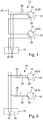
- Fig. 1 and 2 show exemplary embodiments of a system 10 according to the invention for monitoring an RWA (smoke and / or heat exhaust) system.
- RWA smoke and / or heat exhaust
- such a monitoring system 10 comprises in each case by a respective closure element 12 closable smoke and / or heat vent openings, the shutters 12 associated drives 14 and a related to the drives 14 central control unit 16th
- a closure element 12 may i.a.
- a closure element 12 may include a pivotable and / or sliding wing such as in particular a door, a window sash or a flap, or a roller shutter, a blind or the like.
- a system 10 for monitoring a smoke and / or heat exhaust system with several vesch spabaren each by a closure element 12 smoke and / or heat exhaust openings is described based on the present embodiments, such a monitoring system in principle also for monitoring a smoke and / or heat exhaust system be provided only a closure element 12. In principle, such embodiments are also conceivable in which a respective smoke and / or heat exhaust opening can be closed by a plurality of closure elements.
- the drives 14 each include a motor drive unit 18 and a separate control unit 20, which is designed to monitor the function of the motor drive unit 18 and / or the respective drive 14 including the associated closure element 12 at certain time intervals thereon, whether the relevant closure element 12 can be opened and / or closed by the motor drive unit 18.
- the control unit 20 of a respective drive 14 may in particular comprise a microcontroller.
- the control unit 20 of a respective drive 14 may be designed to check whether the relevant closure element 12 has been opened within a respective predeterminable time interval. In this case, the control unit 20 in particular be executed to check whether the closure element 12 in question was open during the entire predetermined time interval.
- the control device 20 or its microcontroller assigned to a respective drive 14 can thus check the function of the respective motor drive unit 18 and / or the possibility of opening the associated closure element at regular time intervals. If the closure element 12 was opened within a respective time interval, for example for ventilation, or if the relevant closure element 12 was open during the entire predeterminable time interval, it can be determined by the respective control device 20 that the motor drive unit 18 and the closure element 12 are functional.
- control device 20 of a respective drive may be designed to carry out a test in the event that the relevant closure element 12 has not been opened within the predefinable time interval or has not been opened during the entire predeterminable time interval.
- control unit 20 of a respective drive 14 for performing a respective test may be designed to control the motor drive unit 18 in the closing direction and to determine the connection resistance of the electric motor drive unit 18 from the motor voltage and the motor current.
- a respective control unit 20 or its microcontroller can thus drive or energize the relevant motor drive unit 18 in the closing direction. If the closure element 12 is closed, then the motor drive unit 18 can not rotate.
- the control unit 20 or its microcontroller from the motor voltage and the motor current calculate the terminal resistance and this example, the value of the data sheet of the engine. If the measured terminal resistance corresponds to the value in the data sheet, the control unit 20 or its microprocessor determines that the motor drive unit 18 is functional.
- control unit 20 of a respective drive can also be designed, in particular, to actuate the motor drive unit 18 in the opening direction and to monitor whether a predeterminable lift or opening angle of the relevant closure element is achieved.
- a respective control unit 20 or its microcontroller can control or energize the respective motor drive unit 18 in the opening direction until a defined stroke or opening angle of the relevant closure element 12 has been reached. If this is the case, this can be assessed by the relevant control unit 20 to the effect that the motor drive unit 18 is functional and the associated closure element 12 can be opened at least up to the predefinable opening angle. Subsequently, the closure element 12 can be closed by a corresponding control of the motor drive unit 18 by the control unit 20 again.
- control unit 20 of a respective drive 14 can also be designed, in particular, to actuate the motor drive unit 18 in the opening direction until the relevant closure element 12 is completely opened.
- the respective control unit 20 or its microcontroller can thus drive or energize the relevant motor drive unit 18 in the opening direction until the relevant closure element 12 is completely open. If the respective open position of the closure element 12 is reached, this can be evaluated by the control unit 20 or its microcontroller to the effect that the motor drive unit 18 and the associated closure element 12 are functional. Subsequently, by a corresponding control of the motor drive unit 18 via the control unit 20, the closure element 12 can be closed again.
- the control device 20 of a respective drive 14 may be connected to detect the open position of the closure element 12 with a closure element contact.
- the control unit 20 of a respective drive 14 for example, be provided with a respective operating state of the relevant motor drive unit 18 and / or the respective closure element 12 signaling output 22, which is in particular the control unit 16 selectively queried for each drive 14 ,
- the respective output 22 may be a potential-free output which opens in the event of a fault.
- This output 22 can be interrogated by the central control unit 16 of the RWA monitoring system 10 for each motor drive unit 18 in order, if appropriate, to display a respective fault.
- closure element contacts in order to detect the open position of the closure elements 12, closure element contacts can be inserted into a monitoring line 24 connected to the central control unit 16 (cf. Fig. 1 ) be looped.
- a monitoring line 24 may be provided in addition to the two of the power supply of the electric motor drive unit 18 serving supply lines 26.
- a respective drive 14 may also include a particular intelligent bus interface 28 and communicate with the central control unit 16 via a particular serial bus connection 30.
- the drives 14 at least partially each have their own address assigned.
- the drives 14 or their control devices 20 can each be designed to report in the case of a trouble-free operating state of the respective motor drive 18 and / or closure element 12 at certain time intervals at the central control unit 16 and / or in the case of a detected fault of respective motor drive 18 and / or closure element 12 to provide an error signal to the central control unit 16.
- each drive 14 on the bus or the bus connection 30 can have a unique address and can be cyclically reported to the central control unit 16. If a respective drive 14 does not respond within a specific time, this can be detected by the central control unit 16 as a fault and signaled, for example, displayed. Thus, each line to a respective drive 14 including the supply lines 26 and the lines of the bus 30 is monitored with. In the present case, the control unit 20 of each drive 14 monitors the respective operating state of the respective motor drive unit 18 and the respective closure element 12. In the simplest case, a respective control unit 20 no longer sends a sign of life, if it has detected a motor or wing error. However, as already mentioned, the respective control unit 20 can also send a specific error signal.
- the drives 14, which are each provided with a particularly intelligent bus interface 28, can be actuated by the central control unit 16, for example also for executing a respective test.
- the testing of a respective motor drive unit 18 and of a respective closure element 12 can thus be initiated by the central control unit 16.
- a respective test can be initiated, for example, when the opening of the closure elements does not lead to any disturbances.
- a particular test may be performed when it is not raining, no wind is blowing, and / or a suitable outside temperature prevails.
- a respective Test either during working hours or outside working hours. It can also be carried out in sections.
- a respective test can be initiated via the central control unit 16 as part of a window maintenance.
- Fig. 1 shows an exemplary embodiment of the monitoring system 10 according to the invention, in which the drives 14 are each provided with an output 22 for signaling the respective operating state of the respective motor drive unit 18 and / or the relevant closure element 12.
- Fig. 2 shows an exemplary embodiment of the monitoring system 10 according to the invention, in which the drives each comprise a particular intelligent bus interface 28.
Landscapes
- Engineering & Computer Science (AREA)
- Structural Engineering (AREA)
- Business, Economics & Management (AREA)
- Emergency Management (AREA)
- Architecture (AREA)
- Health & Medical Sciences (AREA)
- Public Health (AREA)
- Civil Engineering (AREA)
- Chemical & Material Sciences (AREA)
- Combustion & Propulsion (AREA)
- Mechanical Engineering (AREA)
- General Engineering & Computer Science (AREA)
- Power-Operated Mechanisms For Wings (AREA)
- Sampling And Sample Adjustment (AREA)
- Control Of Electric Motors In General (AREA)
Abstract
Description
- Die Erfindung betrifft ein System zur Überwachung einer Rauch- und/oder Wärmeabzugsanlage mit wenigstens einer durch ein jeweiliges Verschlusselement verschließbaren Rauch- und/oder Wärmeabzugsöffnung, wenigstens einem jeweils einem Verschlusselement zugeordneten Antrieb und einer mit dem bzw. den Antrieben in Verbindung stehenden zentralen Steuerungseinheit.
- Derartige System zur Überwachung sogenannter RWA (Rauch- und/oder Wärmeabzugs)-Anlagen sind allgemein bekannt. Sie stellen sicher, dass die durch einen jeweiligen Fensterflügel, Türflügel oder dergleichen verschließbaren Rauch- und/oder Wärmeabzugsöffnungen im Notfall, insbesondere im Brandfall, automatisch öffnen. Im Normalbetrieb dienen solche RWA-Anlagen der Lüftung.
- Bei den bisher üblichen Systemen zur Überwachung einer RWA-Anlage erfolgt in der Regel eine Überwachung der den verschiedenen Flügeln zugeordneten motorischen Antriebe durch eine zentrale Steuerungseinheit. Dazu wird meistens zusätzlich zu den der Spannungsversorgung der motorischen Antriebe dienenden Leitungen eine dritte Leitung als Überwachungsleitung in das betreffende Verbindungskabel zwischen der zentralen Steuerungseinheit und den Antrieben integriert. Dabei wird die Antriebsmotorlinie bisher mit einem Abschlusselement, meistens einer Diode oder einem Widerstand, abgeschlossen. Wird die Überwachungsleitung unterbrochen, so kann dies in der zentralen Steuerungseinheit anhand einer entsprechenden Änderung eines über die Überwachungsleitung übertragenen Signals erfasst werden, das an einem Messwiderstand abgegriffen wird.
- Es sind auch bereits sogenannte intelligente Fensterantriebe bekannt, die zur Erfassung der jeweiligen Position des Fensters bzw. Antriebsmotors und zur Erfassung der Stromaufnahme des Antriebsmotors mit einem Mikrocontroller versehen sind.
- Die bisher bekannten Überwachungssysteme weisen unter anderem den Nachteil auf, dass sie eine zusätzliche Überwachungsleitung benötigen und keine umfassende Überwachung der Funktion der Antriebe und der zu betätigenden Flügel gewährleisten. So können unter anderem Stichleitungen zu den motorischen Antrieben nicht überwacht werden. Zudem kann von der zentralen Steuerungseinheit auch nicht erkannt werden, ob alle motorischen Antriebe in der gewünschten Weise funktionieren und sich auch alle Flügel öffnen lassen oder bestimmte Flügel klemmen.
- Der Erfindung liegt die Aufgabe zugrunde, ein Überwachungssystem der eingangs genannten Art anzugeben, bei dem die zuvor erwähnten Nachteile beseitigt sind. Dabei soll nicht nur eine umfassendere Funktionsüberwachung einer jeweiligen motorischen Antriebseinheit, sondern darüber hinaus auch eine möglichst zuverlässige Überwachung eines jeweiligen Antriebs dahingehend gewährleistet sein, ob sich ein jeweiliges Verschlusselement auch öffnen und/oder schließen lässt oder klemmt.
- Die Aufgabe wird erfindungsgemäß durch ein System mit den Merkmalen des Anspruchs 1 gelöst. Bevorzugte Ausführungsformen des erfindungsgemäßen Systems ergeben sich aus den Unteransprüchen, der vorliegenden Beschreibung sowie der Zeichnung.
- Das erfindungsgemäße System zur Überwachung einer Rauch- und/oder Wärmeabzugsanlage umfasst wenigstens eine durch ein jeweiliges Verschlusselement verschließbare Rauch- und/oder Wärmeabzugsöffnung, wenigstens einen jeweils einem Verschlusselement zugeordneten Antrieb und eine mit dem bzw. den Antrieben in Verbindung stehende zentrale Steuerungseinheit. Ein jeweiliger Antrieb umfasst jeweils eine motorische Antriebseinheit und ein eigenes Steuergerät, wobei ein jeweiliges Steuergerät dazu ausgeführt ist, die Funktion der motorischen Antriebseinheit des betreffenden Antriebs und/oder den betreffenden Antrieb einschließlich des zugeordneten Verschlusselements in bestimmten Zeitabständen daraufhin zu überwachen, ob das betreffende Verschlusselement durch die motorische Antriebseinheit geöffnet und/oder geschlossen werden kann.
- Dabei kann ein Verschlusselement u.a. beispielsweise einen verschwenk- und/oder verschiebbaren Flügel wie insbesondere einen Türflügel, einen Fensterflügel oder eine Klappe, oder einen Rollladen, eine Jalousie oder dergleichen umfassen. Das erfindungsgemäße System kann zur Überwachung einer Rauch- und/oder Wärmeabzugsanlage mit nur einer oder insbesondere auch zur Überwachung einer Rauch- und/oder Wärmeabzugsanlage mit mehreren jeweils durch wenigstens ein solches Verschlusselement verschließbaren Rauch- und/oder Wärmeabzugsöffnungen vorgesehen sein.
- Aufgrund dieser Ausbildung wird nicht nur eine umfassendere Funktionsüberwachung der motorischen Antriebseinheiten, sondern darüber hinaus auch eine zuverlässige Überwachung der Antriebe dahingehend gewährleistet, ob sich alle Verschlusselemente öffnen und/oder schließen lassen oder einzelne Verschlusselemente klemmen oder ein zugeordneter Beschlag gebrochen ist. Damit wird unter anderem auch die Funktionsfähigkeit der zu den einzelnen Antrieben geführten Leitungen überwacht. Ist nämlich nur eine dieser Leitungen defekt, so können mit mehr sämtliche Verschlusselemente geöffnet oder geschlossen werden, was durch das erfindungsgemäße System erkannt wird.
- Bevorzugt umfasst das Steuergerät eines jeweiligen Antriebs einen Mikrocontroller. In diesem Fall übernimmt der Mikrocontroller die betreffende Überwachung.
- Gemäß einer bevorzugten praktischen Ausführungsform des erfindungsgemäßen Systems ist das Steuergerät eines jeweiligen Antriebs dazu ausgeführt, zu überprüfen, ob der betreffende Verschlusselement innerhalb eines jeweiligen vorgebbaren Zeitintervalls geöffnet wurde. Dabei kann das jeweilige Steuergerät insbesondere dazu ausgeführt sein, zu überprüfen, ob das betreffende Verschlusselement während des gesamten vorgebbaren Zeitintervalls geöffnet war.
- Wurde das Verschlusselement innerhalb des betreffenden Zeitintervalls beispielsweise zum Lüften geöffnet bzw. war der betreffende Flügel während des gesamten Zeitintervalls geöffnet, so kann das jeweilige Steuergerät feststellen, dass sowohl die jeweilige motorische Antriebseinheit als auch das jeweilige Verschlusselement funktionsfähig sind.
- Gemäß einer weiteren bevorzugten praktischen Ausführungsform des erfindungsgemäßen Systems ist das Steuergerät eines jeweiligen Antriebs dazu ausgeführt, in dem Fall, dass das betreffende Verschlusselement innerhalb des vorgebbaren Zeitintervalls nicht geöffnet wurde bzw. nicht während des gesamten vorgebbaren Zeitintervalls geöffnet war, einen Test durchzuführen. Umfasst das Steuergerät eines jeweiligen Antriebs einen Mikrocontroller, so startet gegebenenfalls der jeweilige Mikrocontroller einen solchen Test.
- Dabei kann das Steuergerät eines jeweiligen Antriebs zur Durchführung eines jeweiligen Tests insbesondere dazu ausgeführt sein, die motorische Antriebseinheit in Schließrichtung anzusteuern und aus der Motorspannung und dem Motorstrom den Anschlusswiderstand der motorischen Antriebseinheit zu bestimmen.
- Ein jeweiliges Steuergerät bzw. dessen Mikrocontroller kann somit die motorische Antriebseinheit gegebenenfalls in Schließrichtung bestromen. Ist das Verschlusselement geschlossen, so kann sich der Motor der motorischen Antriebseinheit, bei der es sich bevorzugt um eine elektrische motorische Antriebseinheit handelt, nicht drehen. Bei einem Gleichstrom-Motor kann das Steuergerät bzw. dessen Mikrocontroller aus der Motorspannung und dem Motorstrom den Anschlusswiderstand berechnen. Entspricht dieser dem im Datenblatt zum Motor angegebenen Wert, so ist der Motor funktionsfähig. Auch dieser Vergleich kann insbesondere wieder von dem jeweiligen Steuergerät bzw. dessen Mikrocontroller durchgeführt werden.
- Alternativ oder zusätzlich kann das Steuergerät eines jeweiligen Antriebs zur Durchführung eines jeweiligen Tests insbesondere auch dazu ausgeführt sein, die motorische Antriebseinheit in Öffnungsrichtung anzusteuern und zu überwachen, ob ein vorgebbarer Hub oder Öffnungswinkel des betreffenden Verschlusselements erreicht wird.
- Ein jeweiliges Steuergerät bzw. dessen Mikrocontroller kann die jeweilige motorische Antriebseinheit somit in Öffnungsrichtung bestromen, bis ein definierter Hub oder Öffnungswinkel des betreffenden Verschlusselements erreicht ist. Damit kann durch das Steuergerät festgestellt werden, dass die motorische Antriebseinheit funktionsfähig ist und sich das zugeordnete Verschlusselement zumindest teilweise öffnen lässt. Das Verschlusselement kann dann anschließend durch eine entsprechende Ansteuerung des motorischen Antriebs durch das Steuergerät wieder geschlossen werden.
- Gemäß einer weiteren zweckmäßigen praktischen Ausführungsform des erfindungsgemäßen Systems ist das Steuergerät eines jeweiligen Antriebs zur Durchführung eines jeweiligen Tests dazu ausgeführt, die motorische Antriebseinheit in Öffnungsrichtung anzusteuern, bis das betreffende Verschlusselement vollständig geöffnet ist. In diesem Fall wird die motorische Antriebseinheit und das Verschlusselement vom betreffenden Steuergerät bzw. dessen Mikrocontroller dann als funktionsfähig erkannt, wenn das Verschlusselement vollständig geöffnet wurde.
- Anschließend kann durch eine entsprechende Ansteuerung des motorischen Antriebs durch das Steuergerät das Verschlusselement wieder geschlossen werden.
- Dabei kann das Steuergerät eines jeweiligen Antriebs zur Erfassung der Offenlage des Verschlusselements vorteilhafterweise mit einem dem Verschlusselement zugeordneten Verschlusselementkontakt verbunden sein, der bei Erreichen der Offenlage betätigt bzw. geöffnet oder geschlossen wird. So kann ein jeweiliger Antrieb bzw. dessen Steuergerät oder Mikrocontroller mit einem zusätzlichen Verschlusselementkontakt zur Erfassung der Offenlage und beispielsweise einem Binäreingang überwachen, ob das Verschlusselement tatsächlich vollständig offen ist oder geöffnet wurde. Er kann somit beispielsweise auch erfassen, ob Beschlagelemente wie zum Beispiel Ketten, Spindeln, Montagekonsolen und/oder dergleichen voll funktionsfähig sind.
- Gemäß einer bevorzugten praktischen Ausführungsform des erfindungsgemäßen Systems ist das Steuergerät eines jeweiligen Antriebs mit einem den jeweiligen Betriebszustand der betreffenden motorischen Antriebseinheit und/oder des betreffenden Verschlusselements signalisierenden Ausgang versehen, der von der zentralen Steuerungseinheit insbesondere selektiv für jeden Antrieb oder verschiedene Gruppen von Antrieben abfragbar ist.
- Dabei kann es sich bei dem betreffenden Ausgang beispielsweise in einen potentialfreien Ausgang handeln, der im Fehlerfall öffnet. Der Ausgang kann von der zentralen Steuerungseinheit für jeden Antrieb oder verschiedene Gruppen von Antrieben abgefragt werden. Gegebenenfalls kann durch die zentrale Steuerungseinheit in Bezug auf die betreffende motorische Antriebseinheit bzw. das betreffende Verschlusselement eine Störung signalisiert und beispielsweise angezeigt werden. Alternativ oder zusätzlich können jeweilige Störungen auch durch die den motorischen Antriebseinheiten zugeordneten Steuergeräte entsprechend signalisiert werden.
- Im einfachsten Fall kann zur Erfassung der Offenlage des wenigstens einen Verschlusselements beispielsweise auch ein Verschlusselementkontakt in eine mit der zentralen Steuerungseinheit verbundene Überwachungsleitung eingeschleift sein.
- Eine weitere vorteilhafte Ausführungsform des erfindungsgemäßen Systems zeichnet sich dadurch aus, dass ein jeweiliger Antrieb eine insbesondere intelligente Busschnittstelle umfasst und über eine insbesondere serielle Busverbindung mit der zentralen Steuerungseinheit in Verbindung steht.
- Neben der Energieversorgung kann ein jeweiliger Antrieb somit über eine zusätzliche ein- oder mehradrige insbesondere serielle Verbindung mit der zentralen Steuerungseinheit verbunden sein.
- Dabei kann einem jeweiligen Antrieb jeweils eine eigene Adresse zugeordnet sein, oder es können verschiedenen Gruppen von Antrieben unterschiedliche Adressen zugeordnet sein.
- Ein jeweiliger Antrieb bzw. eine jeweilige Gruppe von Antrieben kann sich insbesondere zyklisch über den Bus bei der zentralen Steuerungseinheit melden. Meldet sich ein jeweiliger Antrieb bzw. Gruppe von Antrieben innerhalb eines bestimmten Zeitraums nicht, so wird dies von der zentralen Steuerungseinheit als Störung bewertet. Damit werden wieder sämtliche Leitungen zu einem jeweiligen Antrieb einschließlich der Spannungsversorgungsleitungen und der Busleitungen mit überwacht. Auch in diesem Fall wird durch das Steuergerät eines jeden Antriebs der Betriebszustand der jeweiligen motorischen Antriebseinheit und des jeweiligen Verschlusselements überwacht. Im einfachsten Fall sendet das Steuergerät kein Lebenszeichen mehr, falls es einen Fehler der betreffenden motorischen Antriebseinheit und/oder des betreffenden Verschlusselements erkannt hat. Das einem jeweiligen Antrieb zugeordnete Steuergerät kann jedoch insbesondere auch ein konkretes Fehlersignal an die zentrale Steuerungseinheit senden.
- Ein jeweiliger Antrieb bzw. dessen Steuergerät kann also vorteilhafterweise insbesondere auch dazu ausgeführt sein, sich im Fall eines störungsfreien Betriebszustands des jeweiligen motorischen Antriebs und/oder Verschlusselements in bestimmten Zeitabständen bei der zentralen Steuerungseinheit zu melden und/oder im Fall einer erfassten Störung des jeweiligen motorischen Antriebs und/oder Verschlusselements ein Fehlersignal an die zentrale Steuerungseinheit zu liefern.
- Gemäß einer weiteren bevorzugten praktischen Ausführungsform des erfindungsgemäßen Systems ist ein jeweiliger mit einer insbesondere intelligenten Busschnittstelle versehener Antrieb durch die zentrale Steuereinheit zur Ausführung eines jeweiligen Tests ansteuerbar.
- Dabei kann ein jeweiliger durch die zentrale Steuerungseinheit initiierter Test beispielsweise dann durchgeführt werden, wenn das Öffnen des Verschlusselements hinsichtlich der jeweiligen Witterung unkritisch ist oder den Betrieb im betreffenden Raum nicht stört. So kann ein solcher Test durch die zentrale Steuerungseinheit beispielsweise dann ausgelöst werden, wenn es nicht regnet und/oder kein Wind vorherrscht und/oder eine passende Außentemperatur vorliegt. Ein jeweiliger Test kann gezielt während der Arbeitszeit oder auch außerhalb der Arbeitszeit initiiert werden. Er kann beispielsweise auch abschnittsweise und/oder im Rahmen einer Fensterwartung oder dergleichen durchgeführt werden. Dazu kann die zentrale Steuerungseinheit mit den erforderlichen Sensoren versehen sein und die entsprechenden Kommunikationsverbindungen aufweisen.
- Die elektrische Energieversorgung der Antriebe kann über die zentrale Steuerungseinheit erfolgen. Zudem können die zentrale Steuerungseinheit und/oder die Antriebe insbesondere auch mit Akkumulatoren zur Notstromversorgung versehen sein. Wie bereits erwähnt, ist außer einer Überwachung der einzelnen Antriebe grundsätzlich auch eine gruppenweise Überwachung dieser Antriebe denkbar. Die zentrale Steuerungseinheit kann mit Bedien- und/oder Anzeigeelementen zur visuellen und/oder akustischen Signalisierung eines jeweiligen Betriebszustands der Antriebe bzw. deren motorischen Antriebseinheiten mit zugeordneten Verschlusselementen versehen sein. Zusätzlich können solche Anzeigeelemente insbesondere auch im Bereich der Antriebe vorgesehen sein. Schließlich kann durch das erfindungsgemäße System auch überwacht werden, ob alle Verschlusselemente korrekt geschlossen werden können.
- Die Erfindung wird im Folgenden anhand von Ausführungsbeispielen unter Bezugnahme auf die Zeichnung näher erläutert. In dieser zeigen:
- Fig. 1
- eine schematische Darstellung einer beispielhaften Ausführungsform eines erfindungsgemäßen Systems zur Überwachung einer RWA-Anlage, wobei die Steuergeräte der Antriebe jeweils mit einem Ausgang zur Signalisierung des jeweiligen Betriebszustands der betreffenden motorischen Antriebseinheit und/oder des betreffenden Verschlusselements versehen sind, und
- Fig. 2
- eine schematische Darstellung einer weiteren beispielhaften Ausführungsform des erfindungsgemäßen Überwachungssystems, wobei die Antriebe jeweils eine insbesondere intelligente Busschnittstelle umfassen.
- Die
Fig. 1 und 2 zeigen beispielhafte Ausführungsformen eines erfindungsgemäßen Systems 10 zur Überwachung einer RWA (Rauch- und/oder Wärmeabzugs)-Anlage. - Dabei umfasst ein solches Überwachungssystem 10 jeweils durch ein jeweiliges Verschlusselement 12 verschließbare Rauch- und/oder Wärmeabzugsöffnungen, den Verschlusselementen 12 zugeordnete Antriebe 14 sowie eine mit den Antrieben 14 in Verbindung stehende zentrale Steuerungseinheit 16.
- Ein Verschlusselement 12 kann u.a. beispielsweise einen verschwenk- und/oder verschiebbaren Flügel wie insbesondere einen Türflügel, einen Fensterflügel oder eine Klappe, oder einen Rollladen, eine Jalousie oder dergleichen umfassen. Während anhand der vorliegenden Ausführungsbeispiele ein System 10 zur Überwachung einer Rauch- und/oder Wärmeabzugsanlage mit mehreren jeweils durch ein Verschlusselement 12 veschließbaren Rauch- und/oder Wärmeabzugsöffnungen beschrieben wird, kann ein solches Überwachungssystem grundsätzlich auch zur Überwachung einer Rauch- und/oder Wärmeabzugsanlage mit nur einem Verschlusselement 12 vorgesehen sein. Grundsätzlich sind auch solche Ausführungen denkbar, bei denen eine jeweilige Rauch- und/oder Wärmeabzugsöffnung durch mehrere Verschlusselemente versschließbar ist.
- Die Antriebe 14 umfassen jeweils eine motorische Antriebseinheit 18 und ein eigenes Steuergerät 20, das dazu ausgeführt ist, die Funktion der motorischen Antriebseinheit 18 und/oder den betreffenden Antrieb 14 einschließlich des zugeordneten Verschlusselements 12 in bestimmten Zeitabständen daraufhin zu überwachen, ob das betreffende Verschlusselement 12 durch die motorische Antriebseinheit 18 geöffnet und/oder geschlossen werden kann.
- Das Steuergerät 20 eines jeweiligen Antriebs 14 kann insbesondere einen Mikrocontroller umfassen.
- Das Steuergerät 20 eines jeweiligen Antriebs 14 kann dazu ausgeführt sein, zu überprüfen, ob das betreffende Verschlusselement 12 innerhalb eines jeweiligen vorgebbaren Zeitintervalls geöffnet wurde. Dabei kann das Steuergerät 20 insbesondere auch dazu ausgeführt sein, zu überprüfen, ob das betreffende Verschlusselement 12 während des gesamten vorgebbaren Zeitintervalls geöffnet war.
- Das einem jeweiligen Antrieb 14 zugeordnete Steuergerät 20 bzw. dessen Mikrocontroller kann somit die Funktion der jeweiligen motorischen Antriebseinheit 18 und/oder die Möglichkeit, das zugeordnete Verschlusselement zu öffnen, in regelmäßigen Zeitabständen überprüfen. Wurde das Verschlusselement 12 innerhalb eines jeweiligen Zeitintervalls beispielsweise zum Lüften geöffnet bzw. war das betreffende Verschlusselement 12 während des gesamten vorgebbaren Zeitintervalls offen, so kann seitens des betreffenden Steuergeräts 20 festgestellt werden, dass die motorische Antriebseinheit 18 und das Verschlusselement 12 funktionsfähig sind.
- Zudem kann das Steuergerät 20 eines jeweiligen Antriebs dazu ausgeführt sein, in dem Fall, dass das betreffende Verschlusselement 12 innerhalb des vorgebbaren Zeitintervalls nicht geöffnet wurde bzw. nicht während des gesamten vorgebbaren Zeitintervalls geöffnet war, einen Test durchzuführen.
- In diesem Fall kann das Steuergerät 20 eines jeweiligen Antriebs 14 zur Durchführung eines jeweiligen Tests dazu ausgeführt sein, die motorische Antriebseinheit 18 in Schließrichtung anzusteuern und aus der Motorspannung und dem Motorstrom den Anschlusswiderstand der elektrischen motorischen Antriebseinheit 18 zu bestimmen.
- Ein jeweiliges Steuergerät 20 bzw. dessen Mikrocontroller kann somit die betreffende motorische Antriebseinheit 18 in Schließrichtung ansteuern oder bestromen. Ist das Verschlusselement 12 geschlossen, so kann sich die motorische Antriebseinheit 18 nicht drehen. Bei einem Gleichstrommotor kann das Steuergerät 20 bzw. dessen Mikrocontroller aus der Motorspannung und dem Motorstrom den Anschlusswiderstand berechnen und diesen beispielsweise mit dem Wert des Datenblatts des Motors vergleichen. Entspricht der gemessene Anschlusswiderstand dem Wert im Datenblatt, so stellt das Steuergerät 20 bzw. dessen Mikroprozessor fest, dass die motorische Antriebseinheit 18 funktionsfähig ist.
- Das Steuergerät 20 eines jeweiligen Antriebs kann zur Durchführung eines jeweiligen Tests insbesondere auch dazu ausgeführt sein, die motorische Antriebseinheit 18 in Öffnungsrichtung anzusteuern und zu überwachen, ob ein vorgebbarer Hub oder Öffnungswinkel des betreffenden Verschlusselements erreicht wird.
- In diesem Fall kann ein jeweiliges Steuergerät 20 bzw. dessen Mikrocontroller die betreffende motorische Antriebseinheit 18 in Öffnungsrichtung ansteuern oder bestromen, bis ein definierter Hub oder Öffnungswinkel des betreffenden Verschlusselements 12 erreicht ist. Ist dies der Fall, so kann dies vom betreffenden Steuergerät 20 dahingehend gewertet werden, dass die motorische Antriebseinheit 18 funktionsfähig ist und sich das zugeordnete Verschlusselement 12 zumindest bis zum vorgebbaren Öffnungswinkel öffnen lässt. Anschließend kann das Verschlusselement 12 durch eine entsprechende Ansteuerung der motorischen Antriebseinheit 18 durch das Steuergerät 20 wieder geschlossen werden.
- Das Steuergerät 20 eines jeweiligen Antriebs 14 kann zur Durchführung eines jeweiligen Tests insbesondere auch dazu ausgeführt sein, die motorische Antriebseinheit 18 in Öffnungsrichtung anzusteuern, bis das betreffende Verschlusselement 12 vollständig geöffnet ist.
- In diesem Fall kann das jeweilige Steuergerät 20 bzw. dessen Mikrocontroller die betreffende motorische Antriebseinheit 18 also in Öffnungsrichtung solange ansteuern oder bestromen, bis das betreffende Verschlusselement 12 ganz offen ist. Wird die betreffende Offenstellung des Verschlusselements 12 erreicht, kann dies durch das Steuergerät 20 bzw. dessen Mikrocontroller dahingehend gewertet werden, dass die motorische Antriebseinheit 18 und das zugeordnete Verschlusselement 12 funktionsfähig sind. Anschließend kann durch eine entsprechende Ansteuerung der motorischen Antriebseinheit 18 über das Steuergerät 20 das Verschlusselement 12 wieder geschlossen werden.
- Das Steuergerät 20 eines jeweiligen Antriebs 14 kann zur Erfassung der Offenlage des Verschlusselements 12 mit einem Verschlusselementkontakt verbunden sein.
- Wie insbesondere anhand der
Fig. 1 zu erkennen ist, kann das Steuergerät 20 eines jeweiligen Antriebs 14 beispielsweise mit einem den jeweiligen Betriebszustand der betreffenden motorischen Antriebseinheit 18 und/oder des betreffenden Verschlusselements 12 signalisierenden Ausgang 22 versehen sein, der von der zentralen Steuerungseinheit 16 insbesondere selektiv für jeden Antrieb 14 abfragbar ist. Dabei kann es sich bei dem jeweiligen Ausgang 22 um einen potentialfreien Ausgang handeln, der im Fehlerfall öffnet. Dieser Ausgang 22 kann von der zentralen Steuerungseinheit 16 des RWA-Überwachungssystems 10 für jede motorische Antriebseinheit 18 abgefragt werden, um gegebenenfalls eine jeweilige Störung anzuzeigen werden. Im einfachsten Fall können zur Erfassung der Offenlage der Verschlusselemente 12 Verschlusselementkontakte in eine mit der zentralen Steuerungseinheit 16 verbundene Überwachungsleitung 24 (vgl. insbesondere nochmals dieFig. 1 ) eingeschleift sein. Eine solche Überwachungsleitung 24 kann zusätzlich zu den beiden der Stromversorgung der elektrischen motorischen Antriebseinheit 18 dienenden Versorgungsleitungen 26 vorgesehen sein. - Wie insbesondere anhand der
Fig. 2 zu erkennen ist, kann ein jeweiliger Antrieb 14 auch eine insbesondere intelligente Busschnittstelle 28 umfassen und über eine insbesondere serielle Busverbindung 30 mit der zentralen Steuerungseinheit 16 in Verbindung stehen. Dabei kann den Antrieben 14 zumindest teilweise jeweils eine eigene Adresse zugeordnet sein. - Zudem können die Antriebe 14 bzw. deren Steuergeräte 20 jeweils dazu ausgeführt sein, sich im Fall eines störungsfreien Betriebszustands des jeweiligen motorischen Antriebs 18 und/oder Verschlusselements 12 in bestimmten Zeitabständen bei der zentralen Steuerungseinheit 16 zu melden und/oder im Fall einer erfassten Störung des jeweiligen motorischen Antriebs 18 und/oder Verschlusselements 12 ein Fehlersignal an die zentrale Steuerungseinheit 16 zu liefern.
- Es kann also beispielsweise jeder Antrieb 14 am Bus bzw. der Busverbindung 30 eine eindeutige Adresse besitzen und sich zyklisch bei der zentralen Steuerungseinheit 16 melden. Meldet sich ein jeweiliger Antrieb 14 nicht innerhalb einer bestimmten Zeit, so kann dies von der zentralen Steuerungseinheit 16 als Störung erkannt und signalisiert, beispielsweise angezeigt werden. Damit wird auch jede Leitung zu einem jeweiligen Antrieb 14 einschließlich der Versorgungsleitungen 26 und der Leitungen der Busverbindung 30 mit überwacht. Auch im vorliegenden Fall überwacht das Steuergerät 20 eines jeden Antriebs 14 den jeweiligen Betriebszustand der betreffenden motorischen Antriebseinheit 18 und des betreffenden Verschlusselements 12. Im einfachsten Fall sendet ein jeweiliges Steuergerät 20 kein Lebenszeichen mehr, falls es einen Motor- oder Flügelfehler erkannt hat. Wie bereits erwähnt, kann das jeweilige Steuergerät 20 jedoch auch ein konkretes Fehlersignal senden.
- Die jeweils mit einer insbesondere intelligenten Busschnittstelle 28 versehenen Antriebe 14 können durch die zentrale Steuerungseinheit 16 beispielsweise auch zur Ausführung eines jeweiligen Tests ansteuerbar sein. Das Testen einer jeweiligen motorischen Antriebseinheit 18 und eines jeweiligen Verschlusselements 12 kann also durch die zentrale Steuerungseinheit 16 veranlasst werden. Dabei kann ein jeweiliger Test beispielsweise dann eingeleitet werden, wenn das Öffnen der Verschlusselemente zu keinen Störungen führt. Ein jeweiliger Test kann beispielsweise dann durchgeführt werden, wenn es nicht regnet, kein Wind weht und/oder eine passende Außentemperatur vorherrscht. Zudem kann ein jeweiliger Test wahlweise während der Arbeitszeit oder auch außerhalb der Arbeitszeit erfolgen. Er kann auch abschnittsweise durchgeführt werden. Zudem kann ein jeweiliger Test über die zentrale Steuerungseinheit 16 im Rahmen einer Fensterwartung initiiert werden. Indem die zentrale Steuerungseinheit 16 mit den erforderlichen Sensoren und Kommunikationsverbindungen versehen ist, ist auch eine solche selektive Veranlassung der Tests möglich.
- Wie bereits erwähnt, ist anstelle einer Überwachung der einzelnen Antriebe 14 auch eine gruppenweise Überwachung solcher Antriebe 14 denkbar.
-
Fig. 1 zeigt eine beispielhafte Ausführungsform des erfindungsgemäßen Überwachungssystems 10, bei der die Antriebe 14 jeweils mit einem Ausgang 22 zur Signalisierung des jeweiligen Betriebszustandes der betreffenden motorischen Antriebseinheit 18 und/oder des betreffenden Verschlusselements 12 versehen sind. -
Fig. 2 zeigt eine beispielhafte Ausführungsform des erfindungsgemäßen Überwachungssystems 10, bei der die Antriebe jeweils eine insbesondere intelligente Busschnittstelle 28 umfassen. -
- 10
- System
- 12
- Verschlusselement
- 14
- Antrieb
- 16
- zentrale Steuerungseinheit
- 18
- motorische Antriebseinheit
- 20
- Steuergerät
- 22
- Ausgang
- 24
- Überwachungsleitung
- 26
- Versorgungsleitung
- 28
- Busschnittstelle
- 30
- Busverbindung
Claims (15)
- System (10) zur Überwachung einer Rauch- und/oder Wärmeabzugsanlage, mit wenigstens einer durch ein jeweiliges Verschlusselement (12) verschließbaren Rauch- und/oder Wärmeabzugsöffnung, wenigstens einem jeweils einem Verschlusselement (12) zugeordneten Antrieb (14) und einer mit dem bzw. den Antrieben (14) in Verbindung stehenden zentralen Steuerungseinheit (16), wobei ein jeweiliger Antrieb (14) jeweils eine motorische Antriebseinheit (18) und ein eigenes Steuergerät (20) umfasst und ein jeweiliges Steuergerät (20) dazu ausgeführt ist, die Funktion der motorischen Antriebseinheit des betreffenden Antriebs und/oder den betreffenden Antrieb (14) einschließlich des zugeordneten Verschlusselements (12) in bestimmten Zeitabständen daraufhin zu überwachen, ob das betreffende Verschlusselement (12) durch die motorische Antriebseinheit (18) geöffnet und/oder geschlossen werden kann.
- System nach Anspruch 1,
dadurch gekennzeichnet, dass das Steuergerät (20) eines jeweiligen Antriebs (14) einen Mikrocontroller umfasst. - System nach Anspruch 1 oder 2,
dadurch gekennzeichnet, dass das Steuergerät (20) eines jeweiligen Antriebs (14) dazu ausgeführt ist, zu überprüfen, ob das betreffende Verschlusselement (12) innerhalb eines jeweiligen vorgebbaren Zeitintervalls geöffnet wurde. - System nach Anspruch 3,
dadurch gekennzeichnet, dass das Steuergerät (20) eines jeweiligen Antriebs (14) dazu ausgeführt ist, zu überprüfen, ob das betreffende Verschlusselement (12) während des gesamten vorgebbaren Zeitintervalls geöffnet war. - System nach Anspruch 3 oder 4,
dadurch gekennzeichnet, dass das Steuergerät (20) eines jeweiligen Antriebs (14) dazu ausgeführt ist, in dem Fall, dass das betreffende Verschlusselement (12) innerhalb des vorgebbaren Zeitintervalls nicht geöffnet wurde bzw. nicht während des gesamten vorgebbaren Zeitintervalls geöffnet war, einen Test durchzuführen. - System nach Anspruch 5,
dadurch gekennzeichnet, dass das Steuergerät (20) eines jeweiligen Antriebs (14) zur Durchführung eines jeweiligen Tests dazu ausgeführt ist, die motorische Antriebseinheit (18) in Schließrichtung anzusteuern und aus der Motorspannung und dem Motorstrom den Anschlusswiederstand der motorischen Antriebseinheit (18) zu bestimmen. - System nach Anspruch 5 oder 6,
dadurch gekennzeichnet, dass das Steuergerät (20) eines jeweiligen Antriebs zur Durchführung eines jeweiligen Tests dazu ausgeführt ist, die motorische Antriebseinheit (18) in Öffnungsrichtung anzusteuern und zu überwachen, ob ein vorgebbarer Hub oder Öffnungswinkel des betreffenden Verschlusselements (12) erreicht wird. - System nach zumindest einem der vorstehenden Ansprüche,
dadurch gekennzeichnet, dass das Steuergerät (20) eines jeweiligen Antriebs (14) zur Durchführung eines jeweiligen Tests dazu ausgeführt ist, die motorische Antriebseinheit (18) in Öffnungsrichtung anzusteuern, bis das betreffende Verschlusselement (12) vollständig geöffnet ist. - System nach Anspruch 8,
dadurch gekennzeichnet, dass das Steuergerät (20) eines jeweiligen Antriebs (14) zur Erfassung der Offenlage des Verschlusselements(12) mit einem Verschlusselementkontakt verbunden ist. - System nach Anspruch 8,
dadurch gekennzeichnet, dass zur Erfassung der Offenlage eines jeweiligen Verschlusselements (12) ein diesem zugeordneter Verschlusselementkontakt in eine mit der zentralen Steuerungseinheit verbundene Überwachungsleitung eingeschleift ist. - System nach zumindest einem der vorstehenden Ansprüche,
dadurch gekennzeichnet, dass das Steuergerät (20) eines jeweiligen Antriebs (14) mit einem den jeweiligen Betriebszustand der betreffenden motorischen Antriebseinheit (18) und/oder des betreffenden Verschlusselements (12) signalisierenden Ausgang (22) versehen ist, der von der zentralen Steuerungseinheit (16) insbesondere selektiv für jeden Antrieb (14) oder verschiedene Gruppen von Antrieben abfragbar ist. - System nach zumindest einem der vorstehenden Ansprüche,
dadurch gekennzeichnet, dass ein jeweiliger Antrieb (14) eine insbesondere intelligente Busschnittstelle (28) umfasst und über eine insbesondere serielle Busverbindung (20) mit der zentralen Steuerungseinheit (16) in Verbindung steht. - System nach Anspruch 12,
dadurch gekennzeichnet, dass wenigstens einem Antrieb eine eigene Adresse zugeordnet ist. - System nach Anspruch 12 oder 13,
dadurch gekennzeichnet, dass ein jeweiliger Antrieb (14) bzw. dessen Steuergerät (20) jeweils dazu ausgeführt ist, sich im Fall eines störungsfreien Betriebszustands des jeweiligen motorischen Antriebs (18) und/oder Verschlusselements (12) in bestimmten Zeitabständen bei der zentralen Steuerungseinheit (16) zu melden und/oder im Fall einer erfassten Störung des jeweiligen motorischen Antriebs (18) und/oder Verschlusselements (12) ein Fehlersignal an die zentrale Steuerungseinheit (16) zu liefern. - System nach zumindest einem der vorstehenden Ansprüche,
dadurch gekennzeichnet, dass ein jeweiliger mit einer insbesondere intelligenten Busschnittstelle (28) versehener Antrieb (14) durch die zentrale Steuerungseinheit (16) zur Ausführung eines jeweiligen Tests ansteuerbar ist.
Priority Applications (1)
| Application Number | Priority Date | Filing Date | Title |
|---|---|---|---|
| PL17165344T PL3246504T3 (pl) | 2016-05-03 | 2017-04-06 | Układ do monitorowania instalacji odprowadzania dymu i/lub ciepła |
Applications Claiming Priority (1)
| Application Number | Priority Date | Filing Date | Title |
|---|---|---|---|
| DE102016207559.4A DE102016207559B4 (de) | 2016-05-03 | 2016-05-03 | System zur Überwachung einer Rauch- und/oder Wärmeabzugsanlage |
Publications (3)
| Publication Number | Publication Date |
|---|---|
| EP3246504A2 true EP3246504A2 (de) | 2017-11-22 |
| EP3246504A3 EP3246504A3 (de) | 2017-11-29 |
| EP3246504B1 EP3246504B1 (de) | 2020-02-26 |
Family
ID=58664450
Family Applications (1)
| Application Number | Title | Priority Date | Filing Date |
|---|---|---|---|
| EP17165344.7A Active EP3246504B1 (de) | 2016-05-03 | 2017-04-06 | System zur überwachung einer rauch- und/oder wärmeabzugsanlage |
Country Status (5)
| Country | Link |
|---|---|
| EP (1) | EP3246504B1 (de) |
| CN (1) | CN107339048B (de) |
| DE (1) | DE102016207559B4 (de) |
| DK (1) | DK3246504T3 (de) |
| PL (1) | PL3246504T3 (de) |
Cited By (1)
| Publication number | Priority date | Publication date | Assignee | Title |
|---|---|---|---|---|
| EP4006438A1 (de) * | 2020-11-26 | 2022-06-01 | Belimo Holding AG | Ein hvac-system und zugehörige verfahren |
Families Citing this family (1)
| Publication number | Priority date | Publication date | Assignee | Title |
|---|---|---|---|---|
| FR3159748A1 (fr) * | 2024-03-01 | 2025-09-05 | Zol | Boîtier de surveillance et dispositif d’évacuation de fumée et de chaleur équipé d’un tel boîtier |
Family Cites Families (11)
| Publication number | Priority date | Publication date | Assignee | Title |
|---|---|---|---|---|
| DE19507407B4 (de) * | 1994-03-04 | 2006-03-02 | Geze Gmbh | Einrichtung zur Betätigung und Überwachung von Rauch- und Wärmeabzugsöffnungen |
| GB9415837D0 (en) * | 1994-08-05 | 1994-09-28 | Colt Int Ltd | Safety apparatus |
| CN2268116Y (zh) * | 1996-06-20 | 1997-11-19 | 辛连起 | 防火卷帘门的智能控制箱 |
| DE19647823B4 (de) * | 1996-11-19 | 2005-11-03 | Geze Gmbh | Steuerungs- und Überwachungsvorrichtung für eine Rauch- und Wärmeabzugsanlage |
| CN100394337C (zh) * | 2004-07-09 | 2008-06-11 | 长春现代门窗科技有限公司 | 智能天窗网络监控系统 |
| US7689293B2 (en) * | 2004-10-25 | 2010-03-30 | Smart Door Systems, Inc. | Active oxygen management, fire encirclement, and operational verification system |
| EP1734214A3 (de) * | 2005-06-17 | 2010-02-24 | Actulux A/S | Vorrichtung und Verfahren zum elektrischen Öffnen und Schliessen von Rauchabzügen, Wärmeabzügen und Oberlichtern |
| DE202010008987U1 (de) * | 2010-11-10 | 2011-11-23 | Jet Tageslicht & Rwa Gmbh | Rauchabzugseinrichtung für eine an einem Rahmen anscharnierte Klappe oder Lichtkuppel |
| CN103061640A (zh) * | 2012-12-24 | 2013-04-24 | 青岛尼克利华智能门业有限公司 | 电动门自动关门系统 |
| CN203684998U (zh) * | 2013-10-28 | 2014-07-02 | 福建安麟智能科技股份有限公司 | 防火卷帘控制器用无线按钮盒 |
| EP3087556B1 (de) * | 2013-12-23 | 2021-01-27 | Finsécur | Vorrichtung zur belüftung eines raums, vorrichtung zum schutz eines ortes und verfahren zur belüftung eines ortes |
-
2016
- 2016-05-03 DE DE102016207559.4A patent/DE102016207559B4/de active Active
-
2017
- 2017-04-06 DK DK17165344.7T patent/DK3246504T3/da active
- 2017-04-06 EP EP17165344.7A patent/EP3246504B1/de active Active
- 2017-04-06 PL PL17165344T patent/PL3246504T3/pl unknown
- 2017-05-03 CN CN201710302457.1A patent/CN107339048B/zh active Active
Non-Patent Citations (1)
| Title |
|---|
| None |
Cited By (4)
| Publication number | Priority date | Publication date | Assignee | Title |
|---|---|---|---|---|
| EP4006438A1 (de) * | 2020-11-26 | 2022-06-01 | Belimo Holding AG | Ein hvac-system und zugehörige verfahren |
| WO2022112415A1 (en) * | 2020-11-26 | 2022-06-02 | Belimo Holding Ag | An hvac system and related methods |
| EP4549834A3 (de) * | 2020-11-26 | 2025-10-01 | Belimo Holding AG | Hlk-system und zugehörige verfahren |
| US12595930B2 (en) | 2020-11-26 | 2026-04-07 | Belimo Holding Ag | HVAC system and related methods |
Also Published As
| Publication number | Publication date |
|---|---|
| DE102016207559B4 (de) | 2017-12-14 |
| DK3246504T3 (da) | 2020-06-02 |
| CN107339048B (zh) | 2019-06-25 |
| CN107339048A (zh) | 2017-11-10 |
| EP3246504B1 (de) | 2020-02-26 |
| EP3246504A3 (de) | 2017-11-29 |
| PL3246504T3 (pl) | 2020-09-21 |
| DE102016207559A1 (de) | 2017-11-09 |
Similar Documents
| Publication | Publication Date | Title |
|---|---|---|
| DE102018211829A1 (de) | System zum Aufwecken einer elektronischen Steuereinheit bei Bewegung eines gesteuerten Elements und Schutz gegen eine gegenelektromotorische Kraft | |
| DE60302068T3 (de) | Elektrisches system zur steuerung mindestens eines tors oder einer tür oder eines ähnlichen elements des elektrisch bewegten typs | |
| EP3507165A1 (de) | Verfahren und vorrichtung zur weichendiagnose | |
| DE102015118151A1 (de) | Sicherheitssensor zur Überwachung der Betriebssicherheit einer Anlage | |
| DE102016207559B4 (de) | System zur Überwachung einer Rauch- und/oder Wärmeabzugsanlage | |
| DE102010014806A1 (de) | Torantriebsvorrichtung, damit versehener Gebäudeabschluss, Torsystem und Herstell- und Antriebsverfahren | |
| WO2022167043A1 (de) | Verfahren zur motorischen bewegungsunterstützung einer fahrzeugtür | |
| DE102010000060B4 (de) | Torsteuerungssystem für ein Tor | |
| DE102011017372B4 (de) | Verfahren zum Betätigen einer durch eine Stellvorrichtung verfahrbaren Fahrzeugtür eines Fahrzeugs | |
| EP2762667B1 (de) | Antriebssystem und Verfahren zum Betrieb eines Antriebssystems | |
| DE19607918A1 (de) | Steuerungseinrichtung für einen motorischen Antrieb einer Tür- oder Fensteranlage | |
| EP3299909A1 (de) | Sicherheitsschaltung zum fehlersicheren abschalten einer gefahrbringenden technischen anlage | |
| DE102011078827B4 (de) | Schließeinrichtung einer Gebäudeöffnung | |
| WO2021018943A1 (de) | VERFAHREN ZUM DURCHFÜHREN EINES SCHLIEßVORGANGS, SCHLIEßVORRICHTUNG, SERVEREINRICHTUNG UND KOMMUNIKATIONSENDGERÄT ZUM DURCHFÜHREN EINES DERARTIGEN VERFAHRENS | |
| DE102008003580A1 (de) | Verfahren und Vorrichtung zum Ermitteln einer Referenzposition eines von einem Elektromotor bewegten Schließteils | |
| EP3064692A1 (de) | Feststellanordnung für eine tür | |
| EP3575531B1 (de) | Anlage zur feststellung eines tür- oder fensterflügels | |
| DE102017201942A1 (de) | Feststell- und/oder Notöffnungsanlage | |
| EP3404183B1 (de) | Automatische tür- oder fensteranlage | |
| DE102021111638B4 (de) | Anordnung aus Zwischenstecker und einem damit elektrisch verbundenem Antrieb | |
| DE102019008889A1 (de) | Verfahren zum Validieren der Funktion eines Türkontakt-Sensors einer Fahrzeugtür eines Kraftfahrzeugs | |
| CH708464B1 (de) | Storenantrieb. | |
| DE102015013309B4 (de) | Ausgleichseinheit | |
| EP1932994A1 (de) | Antrieb für einen Flügel einer Tür oder eines Fensters | |
| DE102011107587A1 (de) | Parametriergerät für einen Rohrmotor |
Legal Events
| Date | Code | Title | Description |
|---|---|---|---|
| PUAI | Public reference made under article 153(3) epc to a published international application that has entered the european phase |
Free format text: ORIGINAL CODE: 0009012 |
|
| STAA | Information on the status of an ep patent application or granted ep patent |
Free format text: STATUS: THE APPLICATION HAS BEEN PUBLISHED |
|
| PUAL | Search report despatched |
Free format text: ORIGINAL CODE: 0009013 |
|
| AK | Designated contracting states |
Kind code of ref document: A2 Designated state(s): AL AT BE BG CH CY CZ DE DK EE ES FI FR GB GR HR HU IE IS IT LI LT LU LV MC MK MT NL NO PL PT RO RS SE SI SK SM TR |
|
| AX | Request for extension of the european patent |
Extension state: BA ME |
|
| AK | Designated contracting states |
Kind code of ref document: A3 Designated state(s): AL AT BE BG CH CY CZ DE DK EE ES FI FR GB GR HR HU IE IS IT LI LT LU LV MC MK MT NL NO PL PT RO RS SE SI SK SM TR |
|
| AX | Request for extension of the european patent |
Extension state: BA ME |
|
| RIC1 | Information provided on ipc code assigned before grant |
Ipc: E05F 15/72 20150101AFI20171025BHEP Ipc: A62C 2/24 20060101ALI20171025BHEP Ipc: E05F 1/00 20060101ALI20171025BHEP |
|
| STAA | Information on the status of an ep patent application or granted ep patent |
Free format text: STATUS: REQUEST FOR EXAMINATION WAS MADE |
|
| 17P | Request for examination filed |
Effective date: 20180305 |
|
| RBV | Designated contracting states (corrected) |
Designated state(s): AL AT BE BG CH CY CZ DE DK EE ES FI FR GB GR HR HU IE IS IT LI LT LU LV MC MK MT NL NO PL PT RO RS SE SI SK SM TR |
|
| RIC1 | Information provided on ipc code assigned before grant |
Ipc: E05F 1/00 20060101ALI20190822BHEP Ipc: E05F 15/72 20150101AFI20190822BHEP Ipc: A62C 2/24 20060101ALI20190822BHEP |
|
| GRAP | Despatch of communication of intention to grant a patent |
Free format text: ORIGINAL CODE: EPIDOSNIGR1 |
|
| STAA | Information on the status of an ep patent application or granted ep patent |
Free format text: STATUS: GRANT OF PATENT IS INTENDED |
|
| INTG | Intention to grant announced |
Effective date: 20191014 |
|
| GRAS | Grant fee paid |
Free format text: ORIGINAL CODE: EPIDOSNIGR3 |
|
| GRAA | (expected) grant |
Free format text: ORIGINAL CODE: 0009210 |
|
| STAA | Information on the status of an ep patent application or granted ep patent |
Free format text: STATUS: THE PATENT HAS BEEN GRANTED |
|
| RBV | Designated contracting states (corrected) |
Designated state(s): AL AT BE BG CH CY CZ DK EE ES FI FR GB GR HR HU IE IS IT LI LT LU LV MC MK MT NL NO PL PT RO RS SE SI SK SM TR |
|
| REG | Reference to a national code |
Ref country code: DE Ref legal event code: R108 |
|
| AK | Designated contracting states |
Kind code of ref document: B1 Designated state(s): AL AT BE BG CH CY CZ DK EE ES FI FR GB GR HR HU IE IS IT LI LT LU LV MC MK MT NL NO PL PT RO RS SE SI SK SM TR |
|
| REG | Reference to a national code |
Ref country code: GB Ref legal event code: FG4D Free format text: NOT ENGLISH |
|
| REG | Reference to a national code |
Ref country code: CH Ref legal event code: EP |
|
| REG | Reference to a national code |
Ref country code: AT Ref legal event code: REF Ref document number: 1237819 Country of ref document: AT Kind code of ref document: T Effective date: 20200315 |
|
| REG | Reference to a national code |
Ref country code: IE Ref legal event code: FG4D Free format text: LANGUAGE OF EP DOCUMENT: GERMAN |
|
| REG | Reference to a national code |
Ref country code: DK Ref legal event code: T3 Effective date: 20200526 |
|
| REG | Reference to a national code |
Ref country code: NL Ref legal event code: FP |
|
| REG | Reference to a national code |
Ref country code: SE Ref legal event code: TRGR |
|
| PG25 | Lapsed in a contracting state [announced via postgrant information from national office to epo] |
Ref country code: NO Free format text: LAPSE BECAUSE OF FAILURE TO SUBMIT A TRANSLATION OF THE DESCRIPTION OR TO PAY THE FEE WITHIN THE PRESCRIBED TIME-LIMIT Effective date: 20200526 Ref country code: FI Free format text: LAPSE BECAUSE OF FAILURE TO SUBMIT A TRANSLATION OF THE DESCRIPTION OR TO PAY THE FEE WITHIN THE PRESCRIBED TIME-LIMIT Effective date: 20200226 Ref country code: RS Free format text: LAPSE BECAUSE OF FAILURE TO SUBMIT A TRANSLATION OF THE DESCRIPTION OR TO PAY THE FEE WITHIN THE PRESCRIBED TIME-LIMIT Effective date: 20200226 |
|
| REG | Reference to a national code |
Ref country code: LT Ref legal event code: MG4D |
|
| PG25 | Lapsed in a contracting state [announced via postgrant information from national office to epo] |
Ref country code: BG Free format text: LAPSE BECAUSE OF FAILURE TO SUBMIT A TRANSLATION OF THE DESCRIPTION OR TO PAY THE FEE WITHIN THE PRESCRIBED TIME-LIMIT Effective date: 20200526 Ref country code: IS Free format text: LAPSE BECAUSE OF FAILURE TO SUBMIT A TRANSLATION OF THE DESCRIPTION OR TO PAY THE FEE WITHIN THE PRESCRIBED TIME-LIMIT Effective date: 20200626 Ref country code: GR Free format text: LAPSE BECAUSE OF FAILURE TO SUBMIT A TRANSLATION OF THE DESCRIPTION OR TO PAY THE FEE WITHIN THE PRESCRIBED TIME-LIMIT Effective date: 20200527 Ref country code: LV Free format text: LAPSE BECAUSE OF FAILURE TO SUBMIT A TRANSLATION OF THE DESCRIPTION OR TO PAY THE FEE WITHIN THE PRESCRIBED TIME-LIMIT Effective date: 20200226 Ref country code: HR Free format text: LAPSE BECAUSE OF FAILURE TO SUBMIT A TRANSLATION OF THE DESCRIPTION OR TO PAY THE FEE WITHIN THE PRESCRIBED TIME-LIMIT Effective date: 20200226 |
|
| PG25 | Lapsed in a contracting state [announced via postgrant information from national office to epo] |
Ref country code: PT Free format text: LAPSE BECAUSE OF FAILURE TO SUBMIT A TRANSLATION OF THE DESCRIPTION OR TO PAY THE FEE WITHIN THE PRESCRIBED TIME-LIMIT Effective date: 20200719 Ref country code: ES Free format text: LAPSE BECAUSE OF FAILURE TO SUBMIT A TRANSLATION OF THE DESCRIPTION OR TO PAY THE FEE WITHIN THE PRESCRIBED TIME-LIMIT Effective date: 20200226 Ref country code: LT Free format text: LAPSE BECAUSE OF FAILURE TO SUBMIT A TRANSLATION OF THE DESCRIPTION OR TO PAY THE FEE WITHIN THE PRESCRIBED TIME-LIMIT Effective date: 20200226 Ref country code: SK Free format text: LAPSE BECAUSE OF FAILURE TO SUBMIT A TRANSLATION OF THE DESCRIPTION OR TO PAY THE FEE WITHIN THE PRESCRIBED TIME-LIMIT Effective date: 20200226 Ref country code: RO Free format text: LAPSE BECAUSE OF FAILURE TO SUBMIT A TRANSLATION OF THE DESCRIPTION OR TO PAY THE FEE WITHIN THE PRESCRIBED TIME-LIMIT Effective date: 20200226 Ref country code: CZ Free format text: LAPSE BECAUSE OF FAILURE TO SUBMIT A TRANSLATION OF THE DESCRIPTION OR TO PAY THE FEE WITHIN THE PRESCRIBED TIME-LIMIT Effective date: 20200226 Ref country code: SM Free format text: LAPSE BECAUSE OF FAILURE TO SUBMIT A TRANSLATION OF THE DESCRIPTION OR TO PAY THE FEE WITHIN THE PRESCRIBED TIME-LIMIT Effective date: 20200226 Ref country code: EE Free format text: LAPSE BECAUSE OF FAILURE TO SUBMIT A TRANSLATION OF THE DESCRIPTION OR TO PAY THE FEE WITHIN THE PRESCRIBED TIME-LIMIT Effective date: 20200226 |
|
| PG25 | Lapsed in a contracting state [announced via postgrant information from national office to epo] |
Ref country code: MC Free format text: LAPSE BECAUSE OF FAILURE TO SUBMIT A TRANSLATION OF THE DESCRIPTION OR TO PAY THE FEE WITHIN THE PRESCRIBED TIME-LIMIT Effective date: 20200226 |
|
| PLBE | No opposition filed within time limit |
Free format text: ORIGINAL CODE: 0009261 |
|
| STAA | Information on the status of an ep patent application or granted ep patent |
Free format text: STATUS: NO OPPOSITION FILED WITHIN TIME LIMIT |
|
| PG25 | Lapsed in a contracting state [announced via postgrant information from national office to epo] |
Ref country code: FR Free format text: LAPSE BECAUSE OF NON-PAYMENT OF DUE FEES Effective date: 20200426 Ref country code: LU Free format text: LAPSE BECAUSE OF NON-PAYMENT OF DUE FEES Effective date: 20200406 |
|
| 26N | No opposition filed |
Effective date: 20201127 |
|
| REG | Reference to a national code |
Ref country code: BE Ref legal event code: MM Effective date: 20200430 |
|
| PG25 | Lapsed in a contracting state [announced via postgrant information from national office to epo] |
Ref country code: BE Free format text: LAPSE BECAUSE OF NON-PAYMENT OF DUE FEES Effective date: 20200430 Ref country code: SI Free format text: LAPSE BECAUSE OF FAILURE TO SUBMIT A TRANSLATION OF THE DESCRIPTION OR TO PAY THE FEE WITHIN THE PRESCRIBED TIME-LIMIT Effective date: 20200226 |
|
| PG25 | Lapsed in a contracting state [announced via postgrant information from national office to epo] |
Ref country code: IE Free format text: LAPSE BECAUSE OF NON-PAYMENT OF DUE FEES Effective date: 20200406 |
|
| PG25 | Lapsed in a contracting state [announced via postgrant information from national office to epo] |
Ref country code: TR Free format text: LAPSE BECAUSE OF FAILURE TO SUBMIT A TRANSLATION OF THE DESCRIPTION OR TO PAY THE FEE WITHIN THE PRESCRIBED TIME-LIMIT Effective date: 20200226 Ref country code: MT Free format text: LAPSE BECAUSE OF FAILURE TO SUBMIT A TRANSLATION OF THE DESCRIPTION OR TO PAY THE FEE WITHIN THE PRESCRIBED TIME-LIMIT Effective date: 20200226 Ref country code: CY Free format text: LAPSE BECAUSE OF FAILURE TO SUBMIT A TRANSLATION OF THE DESCRIPTION OR TO PAY THE FEE WITHIN THE PRESCRIBED TIME-LIMIT Effective date: 20200226 |
|
| PG25 | Lapsed in a contracting state [announced via postgrant information from national office to epo] |
Ref country code: MK Free format text: LAPSE BECAUSE OF FAILURE TO SUBMIT A TRANSLATION OF THE DESCRIPTION OR TO PAY THE FEE WITHIN THE PRESCRIBED TIME-LIMIT Effective date: 20200226 Ref country code: AL Free format text: LAPSE BECAUSE OF FAILURE TO SUBMIT A TRANSLATION OF THE DESCRIPTION OR TO PAY THE FEE WITHIN THE PRESCRIBED TIME-LIMIT Effective date: 20200226 |
|
| P01 | Opt-out of the competence of the unified patent court (upc) registered |
Effective date: 20230510 |
|
| PGFP | Annual fee paid to national office [announced via postgrant information from national office to epo] |
Ref country code: NL Payment date: 20230419 Year of fee payment: 7 |
|
| PGFP | Annual fee paid to national office [announced via postgrant information from national office to epo] |
Ref country code: DK Payment date: 20230421 Year of fee payment: 7 Ref country code: CH Payment date: 20230502 Year of fee payment: 7 |
|
| PGFP | Annual fee paid to national office [announced via postgrant information from national office to epo] |
Ref country code: SE Payment date: 20230420 Year of fee payment: 7 |
|
| PGFP | Annual fee paid to national office [announced via postgrant information from national office to epo] |
Ref country code: GB Payment date: 20230419 Year of fee payment: 7 |
|
| REG | Reference to a national code |
Ref country code: DK Ref legal event code: EBP Effective date: 20240430 |
|
| REG | Reference to a national code |
Ref country code: CH Ref legal event code: PL |
|
| REG | Reference to a national code |
Ref country code: SE Ref legal event code: EUG |
|
| REG | Reference to a national code |
Ref country code: NL Ref legal event code: MM Effective date: 20240501 |
|
| GBPC | Gb: european patent ceased through non-payment of renewal fee |
Effective date: 20240406 |
|
| PG25 | Lapsed in a contracting state [announced via postgrant information from national office to epo] |
Ref country code: NL Free format text: LAPSE BECAUSE OF NON-PAYMENT OF DUE FEES Effective date: 20240501 |
|
| PG25 | Lapsed in a contracting state [announced via postgrant information from national office to epo] |
Ref country code: GB Free format text: LAPSE BECAUSE OF NON-PAYMENT OF DUE FEES Effective date: 20240406 |
|
| PG25 | Lapsed in a contracting state [announced via postgrant information from national office to epo] |
Ref country code: NL Free format text: LAPSE BECAUSE OF NON-PAYMENT OF DUE FEES Effective date: 20240501 Ref country code: GB Free format text: LAPSE BECAUSE OF NON-PAYMENT OF DUE FEES Effective date: 20240406 Ref country code: CH Free format text: LAPSE BECAUSE OF NON-PAYMENT OF DUE FEES Effective date: 20240430 |
|
| PG25 | Lapsed in a contracting state [announced via postgrant information from national office to epo] |
Ref country code: DK Free format text: LAPSE BECAUSE OF NON-PAYMENT OF DUE FEES Effective date: 20240430 |
|
| PGFP | Annual fee paid to national office [announced via postgrant information from national office to epo] |
Ref country code: IT Payment date: 20250424 Year of fee payment: 9 |
|
| PGFP | Annual fee paid to national office [announced via postgrant information from national office to epo] |
Ref country code: AT Payment date: 20250423 Year of fee payment: 9 |
|
| PG25 | Lapsed in a contracting state [announced via postgrant information from national office to epo] |
Ref country code: SE Free format text: LAPSE BECAUSE OF NON-PAYMENT OF DUE FEES Effective date: 20240407 |
|
| PGFP | Annual fee paid to national office [announced via postgrant information from national office to epo] |
Ref country code: PL Payment date: 20260326 Year of fee payment: 10 |