EP3246523B1 - Joint refroidi d'air externe d'aube - Google Patents
Joint refroidi d'air externe d'aube Download PDFInfo
- Publication number
- EP3246523B1 EP3246523B1 EP17171798.6A EP17171798A EP3246523B1 EP 3246523 B1 EP3246523 B1 EP 3246523B1 EP 17171798 A EP17171798 A EP 17171798A EP 3246523 B1 EP3246523 B1 EP 3246523B1
- Authority
- EP
- European Patent Office
- Prior art keywords
- raised
- holes
- raised material
- air seal
- blade
- Prior art date
- Legal status (The legal status is an assumption and is not a legal conclusion. Google has not performed a legal analysis and makes no representation as to the accuracy of the status listed.)
- Active
Links
Images


Classifications
-
- F—MECHANICAL ENGINEERING; LIGHTING; HEATING; WEAPONS; BLASTING
- F01—MACHINES OR ENGINES IN GENERAL; ENGINE PLANTS IN GENERAL; STEAM ENGINES
- F01D—NON-POSITIVE DISPLACEMENT MACHINES OR ENGINES, e.g. STEAM TURBINES
- F01D11/00—Preventing or minimising internal leakage of working-fluid, e.g. between stages
- F01D11/08—Preventing or minimising internal leakage of working-fluid, e.g. between stages for sealing space between rotor blade tips and stator
-
- F—MECHANICAL ENGINEERING; LIGHTING; HEATING; WEAPONS; BLASTING
- F01—MACHINES OR ENGINES IN GENERAL; ENGINE PLANTS IN GENERAL; STEAM ENGINES
- F01D—NON-POSITIVE DISPLACEMENT MACHINES OR ENGINES, e.g. STEAM TURBINES
- F01D25/00—Component parts, details, or accessories, not provided for in, or of interest apart from, other groups
- F01D25/24—Casings; Casing parts, e.g. diaphragms, casing fastenings
- F01D25/246—Fastening of diaphragms or stator-rings
-
- F—MECHANICAL ENGINEERING; LIGHTING; HEATING; WEAPONS; BLASTING
- F02—COMBUSTION ENGINES; HOT-GAS OR COMBUSTION-PRODUCT ENGINE PLANTS
- F02C—GAS-TURBINE PLANTS; AIR INTAKES FOR JET-PROPULSION PLANTS; CONTROLLING FUEL SUPPLY IN AIR-BREATHING JET-PROPULSION PLANTS
- F02C3/00—Gas-turbine plants characterised by the use of combustion products as the working fluid
- F02C3/04—Gas-turbine plants characterised by the use of combustion products as the working fluid having a turbine driving a compressor
-
- F—MECHANICAL ENGINEERING; LIGHTING; HEATING; WEAPONS; BLASTING
- F05—INDEXING SCHEMES RELATING TO ENGINES OR PUMPS IN VARIOUS SUBCLASSES OF CLASSES F01-F04
- F05D—INDEXING SCHEME FOR ASPECTS RELATING TO NON-POSITIVE-DISPLACEMENT MACHINES OR ENGINES, GAS-TURBINES OR JET-PROPULSION PLANTS
- F05D2220/00—Application
- F05D2220/30—Application in turbines
- F05D2220/32—Application in turbines in gas turbines
-
- F—MECHANICAL ENGINEERING; LIGHTING; HEATING; WEAPONS; BLASTING
- F05—INDEXING SCHEMES RELATING TO ENGINES OR PUMPS IN VARIOUS SUBCLASSES OF CLASSES F01-F04
- F05D—INDEXING SCHEME FOR ASPECTS RELATING TO NON-POSITIVE-DISPLACEMENT MACHINES OR ENGINES, GAS-TURBINES OR JET-PROPULSION PLANTS
- F05D2230/00—Manufacture
- F05D2230/10—Manufacture by removing material
- F05D2230/11—Manufacture by removing material by electrochemical methods
-
- F—MECHANICAL ENGINEERING; LIGHTING; HEATING; WEAPONS; BLASTING
- F05—INDEXING SCHEMES RELATING TO ENGINES OR PUMPS IN VARIOUS SUBCLASSES OF CLASSES F01-F04
- F05D—INDEXING SCHEME FOR ASPECTS RELATING TO NON-POSITIVE-DISPLACEMENT MACHINES OR ENGINES, GAS-TURBINES OR JET-PROPULSION PLANTS
- F05D2230/00—Manufacture
- F05D2230/20—Manufacture essentially without removing material
- F05D2230/21—Manufacture essentially without removing material by casting
-
- F—MECHANICAL ENGINEERING; LIGHTING; HEATING; WEAPONS; BLASTING
- F05—INDEXING SCHEMES RELATING TO ENGINES OR PUMPS IN VARIOUS SUBCLASSES OF CLASSES F01-F04
- F05D—INDEXING SCHEME FOR ASPECTS RELATING TO NON-POSITIVE-DISPLACEMENT MACHINES OR ENGINES, GAS-TURBINES OR JET-PROPULSION PLANTS
- F05D2240/00—Components
- F05D2240/10—Stators
- F05D2240/11—Shroud seal segments
-
- F—MECHANICAL ENGINEERING; LIGHTING; HEATING; WEAPONS; BLASTING
- F05—INDEXING SCHEMES RELATING TO ENGINES OR PUMPS IN VARIOUS SUBCLASSES OF CLASSES F01-F04
- F05D—INDEXING SCHEME FOR ASPECTS RELATING TO NON-POSITIVE-DISPLACEMENT MACHINES OR ENGINES, GAS-TURBINES OR JET-PROPULSION PLANTS
- F05D2250/00—Geometry
- F05D2250/20—Three-dimensional
- F05D2250/21—Three-dimensional pyramidal
-
- F—MECHANICAL ENGINEERING; LIGHTING; HEATING; WEAPONS; BLASTING
- F05—INDEXING SCHEMES RELATING TO ENGINES OR PUMPS IN VARIOUS SUBCLASSES OF CLASSES F01-F04
- F05D—INDEXING SCHEME FOR ASPECTS RELATING TO NON-POSITIVE-DISPLACEMENT MACHINES OR ENGINES, GAS-TURBINES OR JET-PROPULSION PLANTS
- F05D2250/00—Geometry
- F05D2250/20—Three-dimensional
- F05D2250/23—Three-dimensional prismatic
- F05D2250/231—Three-dimensional prismatic cylindrical
-
- F—MECHANICAL ENGINEERING; LIGHTING; HEATING; WEAPONS; BLASTING
- F05—INDEXING SCHEMES RELATING TO ENGINES OR PUMPS IN VARIOUS SUBCLASSES OF CLASSES F01-F04
- F05D—INDEXING SCHEME FOR ASPECTS RELATING TO NON-POSITIVE-DISPLACEMENT MACHINES OR ENGINES, GAS-TURBINES OR JET-PROPULSION PLANTS
- F05D2250/00—Geometry
- F05D2250/20—Three-dimensional
- F05D2250/23—Three-dimensional prismatic
- F05D2250/232—Three-dimensional prismatic conical
-
- F—MECHANICAL ENGINEERING; LIGHTING; HEATING; WEAPONS; BLASTING
- F05—INDEXING SCHEMES RELATING TO ENGINES OR PUMPS IN VARIOUS SUBCLASSES OF CLASSES F01-F04
- F05D—INDEXING SCHEME FOR ASPECTS RELATING TO NON-POSITIVE-DISPLACEMENT MACHINES OR ENGINES, GAS-TURBINES OR JET-PROPULSION PLANTS
- F05D2260/00—Function
- F05D2260/60—Fluid transfer
- F05D2260/607—Preventing clogging or obstruction of flow paths by dirt, dust, or foreign particles
-
- Y—GENERAL TAGGING OF NEW TECHNOLOGICAL DEVELOPMENTS; GENERAL TAGGING OF CROSS-SECTIONAL TECHNOLOGIES SPANNING OVER SEVERAL SECTIONS OF THE IPC; TECHNICAL SUBJECTS COVERED BY FORMER USPC CROSS-REFERENCE ART COLLECTIONS [XRACs] AND DIGESTS
- Y02—TECHNOLOGIES OR APPLICATIONS FOR MITIGATION OR ADAPTATION AGAINST CLIMATE CHANGE
- Y02T—CLIMATE CHANGE MITIGATION TECHNOLOGIES RELATED TO TRANSPORTATION
- Y02T50/00—Aeronautics or air transport
- Y02T50/60—Efficient propulsion technologies, e.g. for aircraft
Definitions
- the present invention relates to blade outer air seals (BOAS) and to a method to prevent obstruction of BOAS inlet holes via particles.
- BOAS blade outer air seals
- Blade outer air seals can be disposed in turbine sections of turbomachines with inlet holes for cooling these hot section components.
- inlet holes of these hot section components can be exposed to particles and other debris.
- EP 1990507 A1 discloses an impingement cooled structure that cools hot walls of a turbine shroud and a turbine end wall.
- US 2007/048122 A1 discloses a filtering technique for air cooling passages in a blade outer air seal. Cooling inlet passages in the blade outer air seal are provided with a filtering technique to filter impurities before they can reach a metering location. A plurality of openings are provided which each have a small cross-sectional area when compared to the cross-sectional area of the metering location. These small openings will filter out impurities before they reach the metering location.
- the metering location has a cross-sectional area that is greater than the cross-sectional area of any one of the openings, however, the total cross-sectional area of the plurality of openings exceeds the cross-sectional area of the metering location such that adequate air is supplied even if several of the openings are clogged.
- EP 2666972 A2 discloses a turbine shroud cooling assembly for cooling turbine shrouds of gas turbine systems.
- US 2015/240721 A1 discloses a component including a porous portion which may be permeable or impermeable to air.
- EP 3054113 A1 discloses an impingement cooled component including a first wall having a plurality of impingement holes and a second wall spaced apart from the first wall (Art. 54(3) EPC).
- EP 3095962 A1 discloses a heat exchanger for a gas turbine engine (Art. 54(3) EPC).
- US 3918835 A discloses a centrifugal filter for coolant passages for turbine blades of a gas turbine.
- a blade outer air seal for a gas turbine engine comprising: a body including lateral edges, radial edges, and an outer surface, wherein the lateral edges and the radial edges provide sealing and containment for a rotating turbomachine blade, the outer surface of the body including a plurality of raised material surfaces that are spaced about the outer surface, the plurality of raised material surfaces extending beyond the outer surface of the body, the plurality of raised material surfaces comprising chamfered edges and being substantially smaller than the outer surface, a plurality of holes distributed among the plurality of raised material surfaces, wherein the plurality of holes are a plurality of raised inlet holes formed through the plurality of raised material surfaces and formed perpendicular to the body so that each of the plurality of holes is raised above the body, and wherein the plurality of raised surfaces create convoluted air flow paths to be received by the plurality of holes, and wherein the radial edges include exit holes in fluid communication with the plurality of raised inlet holes.
- a gas turbine engine includes a turbine section including a plurality of the previously described blade outer air seals disposed therein.
- a method to prevent obstruction of inlet holes via particles comprising: providing an airflow to a blade outer air seal; and directing the airflow in a convoluted airflow path to divert the particles via the blade outer air seal, the blade outer air seal including: a body including lateral edges, radial edges, and an outer surface, wherein the lateral edges and the radial edges provide sealing and containment for a rotating turbomachine blade, the outer surface of the body including a plurality of raised material surfaces that are spaced about the outer surface, the plurality of raised material surfaces extending beyond the outer surface of the body, the plurality of raised material surfaces comprising chamfered edges and being substantially smaller than the outer surface, a plurality of holes distributed among the plurality of raised material surfaces, wherein the plurality of holes are a plurality of raised inlet holes formed through the plurality of raised material surfaces and formed perpendicular to the body so that each of the plurality of holes is raised above the body, and wherein the plurality of raised surfaces create
- FIG. 3 an illustrative view of an embodiment of a blade outer air seal (BOAS) in accordance with the disclosure is shown in Fig. 3 and is designated generally by reference character 300.
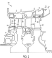
- Other embodiments and/or aspects of this disclosure are shown in Figs. 1 and 2 .
- the systems and methods described herein can be used to provide enhanced particle avoidance for inlet holes of a BOAS.
- Fig. 1 schematically illustrates a gas turbine engine 20.
- the gas turbine engine 20 is disclosed herein as a two-spool turbofan that generally incorporates a fan section 22, a compressor section 24, a combustor section 26 and a turbine section 28.
- Alternative engines might include an augmentor section (not shown) among other systems or features.
- the fan section 22 drives air along a bypass flow path B in a bypass duct defined within a nacelle 15, while the compressor section 24 drives air along a core flow path C for compression and communication into the combustor section 26 then expansion through the turbine section 28.
- the illustrated engine 20 generally includes a low speed spool 30 and a high speed spool 32 mounted for rotation about an engine central longitudinal axis A relative to an engine static structure 36 via several bearing systems 38. It should be understood that various bearing systems 38 at various locations may alternatively or additionally be provided and the location of bearing systems 38 may be varied as appropriate to the application.
- the low speed spool 30 generally includes an inner shaft 40 that interconnects a fan 42, a first (or low) pressure compressor 44 and a first (or low) pressure turbine 46.
- the inner shaft 40 is connected to the fan 42 through a speed change mechanism, which in illustrated gas turbine engine 20 is illustrated as a gear system 48 to drive the fan 42 at a lower speed than the low speed spool 30.
- the high speed spool 32 includes an outer shaft 50 that interconnects a second (or high) pressure compressor 52 and a second (or high) pressure turbine 54.
- a combustor 56 is arranged in exemplary gas turbine 20 between the high pressure compressor 52 and the high pressure turbine 54.
- a mid-turbine frame 57 of the engine static structure 36 is arranged generally between the high pressure turbine 54 and the low pressure turbine 46.
- the mid-turbine frame 57 further supports bearing systems 38 in the turbine section 28.
- the inner shaft 40 and the outer shaft 50 are concentric and rotate via bearing systems 38 about the engine central longitudinal axis A which is colline
- the core airflow is compressed by the low pressure compressor 44 then the high pressure compressor 52, mixed and burned with fuel in the combustor 56, then expanded over the high pressure turbine 54 and low pressure turbine 46.
- the mid-turbine frame 57 includes airfoils 59 which are in the core airflow path C.
- the turbines 46, 54 rotationally drive the respective low speed spool 30 and high speed spool 32 in response to the expansion.
- gear system 48 may be located aft of combustor section 26 or even aft of turbine section 28, and fan section 22 may be positioned forward or aft of the location of gear system 48.
- the engine 20 in one example is a high-bypass geared aircraft engine.
- the engine 20 bypass ratio is greater than about six (6), with an example embodiment being greater than about ten (10)
- the geared architecture is an epicyclic gear train, such as a planetary gear system or other gear system, with a gear reduction ratio of greater than about 2.3 and the low pressure turbine 46 has a pressure ratio that is greater than about five.
- the engine 20 bypass ratio is greater than about ten (10:1)
- the fan diameter is significantly larger than that of the low pressure compressor 44
- the low pressure turbine 46 has a pressure ratio that is greater than about five (5:1).
- Low pressure turbine 46 pressure ratio is pressure measured prior to inlet of low pressure turbine 46 as related to the pressure at the outlet of the low pressure turbine 46 prior to an exhaust nozzle.
- the geared architecture may be an epicycle gear train, such as a planetary gear system or other gear system, with a gear reduction ratio of greater than about 2.3:1. It should be understood, however, that the above parameters are only exemplary of one embodiment of a geared architecture engine and that the present invention is applicable to other gas turbine engines including direct drive turbofans.
- the fan section 22 of the engine 20 is designed for a particular flight condition - typically cruise at about 0.8 Mach and about 35,000 feet (10,668 metres).
- the flight condition of 0.8 Mach and 35,000 ft (10,668 meters), with the engine at its best fuel consumption- also known as "bucket cruise Thrust Specific Fuel Consumption ('TSFC')"- is the industry standard parameter of lbm of fuel being burned divided by lbf of thrust the engine produces at that minimum point.
- “Low fan pressure ratio” is the pressure ratio across the fan blade alone, without a Fan Exit Guide Vane 79 (“FEGV”) system.
- the low fan pressure ratio as disclosed herein according to one non-limiting embodiment is less than about 1.45.
- Low corrected fan tip speed is the actual fan tip speed in ft/sec divided by an industry standard temperature correction of [(Tram °R) / (518.7 °R)] ⁇ 0.5.
- the "Low corrected fan tip speed” as disclosed herein according to one non-limiting embodiment is less than about 1150 ft / second (350.5 meters/second).
- a turbine section 200 is shown including a plurality of blade outer air seals (BOAS) 300, blades 301 and vanes 302.
- the turbine section 200 can include at least one BOAS 300, blade 301, or vane 302 having inlet holes formed in raised material as described herein.
- the at least one BOAS 300 can be disposed in a first stage 201 of the turbine section 200.
- Another BOAS 300 can be disposed in a second stage 203 of the turbine section 200 which is aft of the first stage 201.
- a BOAS 300 is shown. Leakage of flow-path air may occur in turbomachinery between the tips of a rotating blade structure and the outer static structure.
- the cooled BOAS 300 can be used to provide a sealing relationship between a rotating turbomachine blade (e.g., a turbine blade) and a stationary component of a turbomachine to prevent flow from leaking around a tip of the turbomachine blade.
- the cooled BOAS 300 includes a body 305 with inlet holes 310 and surface 311. During operation, debris and particles present in the airflow may block or otherwise obstruct inlet holes 310, preventing cooling of the cooled BOAS 300, especially in desert environments. By raising the inlet holes 310 above the cooled BOAS body 305, performance, safety, and durability can be maintained, preventing repairs and replacements of the cooled BOAS 300 and other components.
- the BOAS body 305 includes lateral edges 303 and 304, radial edges 308 and 306, and a cooled BOAS outer surface 324.
- the lateral edges 303, 304 and the radial edges 308, 306 provide sealing and containment for a rotating turbomachine blade.
- the cooled BOAS outer surface 324 can receive cooling airflow that may be directed to the inlet holes 310.
- the cooling airflow may include particles and other debris that can obstruct the inlet holes 310.
- a of inlet holes are formed in the cooled BOAS body 305.
- the inlet holes 310 can be cast, drilled, electrical discharge machined, etc. into the cooled BOAS body 305.
- the inlet holes 310 are formed perpendicularly relative to the cooled BOAS 305.
- the inlet holes 310 are in fluid communication with exit holes 321 to allow for a desired airflow path.
- the inlet holes 310 can allow for a cooling airflow to cool the cooled BOAS 300.
- the inlet holes 310 are formed through surface 311.
- the surface 311 is raised relative to the cooled BOAS outer surface 324 to prevent debris and particles present in the airflow from entering the inlet holes 310.
- the inlet holes 310 are formed on the raised surface 311.
- the raised surface 311 can have a generally prismatoidal, conical, hemispherical or round shape.
- the raised surface 311 can be cast as part of the cooled BOAS body 305.
- the raised surface transitions to the cooled hot section component outer surface 324 via an edge 322. According to the invention, the edge 322 is chamfered to improve flow characteristics or reduce stress concentrations.
- the raised surface 311 is substantially smaller than the cooled BOAS outer surface 324.
- raised surface 311 creates convoluted air flow paths to be received by the inlet holes 310.
- the convoluted paths can divert dirt and particles from the inlet holes 310 by moving the inlet holes 310 away from flush surfaces such as the cooled BOAS outer surface 324.
- the raised surface 311 can reduce the amount of particles in the airflow through inlet holes 310 while having a minimal effect on weight, cost and performance of the cooled BOAS 300.
- the raised surface 311 can be retrofit or otherwise can be added to existing cooled hot section components.
Landscapes
- Engineering & Computer Science (AREA)
- Mechanical Engineering (AREA)
- General Engineering & Computer Science (AREA)
- Chemical & Material Sciences (AREA)
- Combustion & Propulsion (AREA)
- Turbine Rotor Nozzle Sealing (AREA)
Claims (7)
- Joint d'air externe d'aube (300) pour un moteur à turbine à gaz (20), comprenant :un corps (305) comportant des bords latéraux (302), (304), des bords radiaux (308), (306) et une surface extérieure (324), dans lequel les bords latéraux (302), (304) et les bords radiaux (308), (306) assurent l'étanchéité et le confinement d'une aube rotative de turbomachine, la surface extérieure (324) du corps (305) comportant une pluralité de surfaces de matériau surélevées (311) qui sont espacées autour de la surface extérieure (324), la pluralité de surfaces de matériau surélevées s'étendant au-delà de la surface extérieure (324) du corps (305), la pluralité de surfaces de matériau surélevées comprenant des bords chanfreinés (322) et étant sensiblement plus petites que la surface extérieure (324),une pluralité de trous (310) répartis parmi la pluralité de surfaces de matériau surélevées (311), dans lequel la pluralité de trous (310) sont une pluralité de trous d'entrée surélevés (310) formés à travers la pluralité de surfaces de matériau surélevées (311) et formées perpendiculairement au corps (305) de sorte que chacun de la pluralité de trous (310) est surélevé au-dessus du corps (305), et dans lequella pluralité de surfaces surélevées (311) crée des chemins d'écoulement d'air sinueux devant être reçus par la pluralité de trous (310), etdans lequel les bords radiaux (308, 306) comportent des trous de sortie (321) en communication fluidique avec la pluralité de trous d'entrée surélevés (310).
- Joint d'air externe d'aube selon la revendication 1, dans lequel le matériau surélevé est prismatoïde.
- Joint d'air externe d'aube selon la revendication 1, dans lequel le matériau surélevé est cylindrique.
- Joint d'air externe d'aube selon la revendication 1, dans lequel le matériau surélevé est conique.
- Joint d'air externe d'aube selon la revendication 1, dans lequel le matériau surélevé est hémisphérique.
- Moteur à turbine à gaz (20), comprenant :
une section de turbine (28 ; 200) comportant une pluralité de joints d'air externe d'aube (300) selon une quelconque revendication précédente. - Procédé pour empêcher l'obstruction des trous d'entrée (310) par des particules, le procédé comprenant :la fourniture d'un flux d'air à un joint d'air externe d'aube (300) ; etla direction du flux d'air dans un chemin d'écoulement d'air sinueux pour dévier les particules par l'intermédiaire du joint d'air externe d'aube, le joint d'air externe d'aube comportant :un corps (305) comportant des bords latéraux (302), (304), des bords radiaux (308), (306) et une surface extérieure (324), dans lequel les bords latéraux (302), (304) et les bords radiaux (308), (306) assurent l'étanchéité et le confinement d'une aube rotative de turbomachine, la surface extérieure (324) du corps (305) comportant une pluralité de surfaces de matériau surélevées (311) qui sont espacées autour de la surface extérieure (324), la pluralité de surfaces de matériau surélevées s'étendant au-delà de la surface extérieure (324) du corps (305), la pluralité de surfaces de matériau surélevées comprenant des bords chanfreinés (322) et étant sensiblement plus petites que la surface extérieure (324),une pluralité de trous (310) répartis parmi la pluralité de surfaces de matériau surélevées (311), dans lequel la pluralité de trous (310) sont une pluralité de trous d'entrée surélevés (310) formés à travers la pluralité de surfaces de matériau surélevées (311) et formées perpendiculairement au corps (305) de sorte que chacun de la pluralité de trous (310) est surélevé au-dessus du corps (305), et dans lequella pluralité de surfaces surélevées (311) crée des chemins d'écoulement d'air sinueux devant être reçus par la pluralité de trous (310), etdans lequel les bords radiaux (308, 306) comportent des trous de sortie (321) en communication fluidique avec la pluralité de trous d'entrée surélevés (310).
Applications Claiming Priority (1)
| Application Number | Priority Date | Filing Date | Title |
|---|---|---|---|
| US15/158,782 US10344611B2 (en) | 2016-05-19 | 2016-05-19 | Cooled hot section components for a gas turbine engine |
Publications (2)
| Publication Number | Publication Date |
|---|---|
| EP3246523A1 EP3246523A1 (fr) | 2017-11-22 |
| EP3246523B1 true EP3246523B1 (fr) | 2022-01-26 |
Family
ID=58715133
Family Applications (1)
| Application Number | Title | Priority Date | Filing Date |
|---|---|---|---|
| EP17171798.6A Active EP3246523B1 (fr) | 2016-05-19 | 2017-05-18 | Joint refroidi d'air externe d'aube |
Country Status (2)
| Country | Link |
|---|---|
| US (1) | US10344611B2 (fr) |
| EP (1) | EP3246523B1 (fr) |
Families Citing this family (7)
| Publication number | Priority date | Publication date | Assignee | Title |
|---|---|---|---|---|
| US11008872B2 (en) * | 2018-12-14 | 2021-05-18 | Raytheon Technologies Corporation | Extension air feed hole blockage preventer for a gas turbine engine |
| US11073024B2 (en) | 2018-12-14 | 2021-07-27 | Raytheon Technologies Corporation | Shape recessed surface cooling air feed hole blockage preventer for a gas turbine engine |
| US11078796B2 (en) | 2018-12-14 | 2021-08-03 | Raytheon Technologies Corporation | Redundant entry cooling air feed hole blockage preventer for a gas turbine engine |
| US11073036B2 (en) * | 2019-06-03 | 2021-07-27 | Raytheon Technologies Corporation | Boas flow directing arrangement |
| US11619136B2 (en) | 2019-06-07 | 2023-04-04 | Raytheon Technologies Corporation | Fatigue resistant blade outer air seal |
| US10961862B2 (en) | 2019-06-07 | 2021-03-30 | Raytheon Technologies Corporation | Fatigue resistant blade outer air seal |
| US11401830B2 (en) | 2019-09-06 | 2022-08-02 | Raytheon Technologies Corporation | Geometry for a turbine engine blade outer air seal |
Family Cites Families (14)
| Publication number | Priority date | Publication date | Assignee | Title |
|---|---|---|---|---|
| US3054113A (en) * | 1960-05-19 | 1962-09-18 | Hat Corp America | Double brim hat |
| US3095962A (en) * | 1961-01-11 | 1963-07-02 | Sperry Rand Corp | Conveying apparatus |
| US3918835A (en) | 1974-12-19 | 1975-11-11 | United Technologies Corp | Centrifugal cooling air filter |
| DE59806535D1 (de) | 1997-02-20 | 2003-01-16 | Siemens Ag | Turbinenschaufel sowie deren verwendung in einer gasturbinenanlage |
| US7306424B2 (en) * | 2004-12-29 | 2007-12-11 | United Technologies Corporation | Blade outer seal with micro axial flow cooling system |
| US20070048122A1 (en) * | 2005-08-30 | 2007-03-01 | United Technologies Corporation | Debris-filtering technique for gas turbine engine component air cooling system |
| EP1990507B1 (fr) | 2006-03-02 | 2015-04-15 | IHI Corporation | Structure de refroidissement par contact |
| EP2844839A1 (fr) | 2012-04-23 | 2015-03-11 | General Electric Company | Profil aérodynamique de turbine à commande d'épaisseur de paroi locale |
| US20130315719A1 (en) | 2012-05-25 | 2013-11-28 | General Electric Company | Turbine Shroud Cooling Assembly for a Gas Turbine System |
| US20130340966A1 (en) * | 2012-06-21 | 2013-12-26 | United Technologies Corporation | Blade outer air seal hybrid casting core |
| US9903275B2 (en) | 2014-02-27 | 2018-02-27 | Pratt & Whitney Canada Corp. | Aircraft components with porous portion and methods of making |
| US9970319B2 (en) | 2014-05-05 | 2018-05-15 | United Technologies Corporation | Reducing variation in cooling hole meter length |
| US10641099B1 (en) | 2015-02-09 | 2020-05-05 | United Technologies Corporation | Impingement cooling for a gas turbine engine component |
| GB201508551D0 (en) | 2015-05-19 | 2015-07-01 | Rolls Royce Plc | A heat exchanger for a gas turbine engine |
-
2016
- 2016-05-19 US US15/158,782 patent/US10344611B2/en active Active
-
2017
- 2017-05-18 EP EP17171798.6A patent/EP3246523B1/fr active Active
Also Published As
| Publication number | Publication date |
|---|---|
| US20170335707A1 (en) | 2017-11-23 |
| US10344611B2 (en) | 2019-07-09 |
| EP3246523A1 (fr) | 2017-11-22 |
Similar Documents
| Publication | Publication Date | Title |
|---|---|---|
| EP3246523B1 (fr) | Joint refroidi d'air externe d'aube | |
| US20160201474A1 (en) | Gas turbine engine component with film cooling hole feature | |
| WO2014138320A1 (fr) | Composant de moteur à turbine à gaz ayant une fente de joint à couvre-joint à largeur variable | |
| EP3239472B1 (fr) | Segment d'arc d'étanchéité avec les côtés circonférentiels inclinés | |
| EP3091186B1 (fr) | Composant de moteur à turbine comprenant un passage central de l'enveloppe aligné axialement interrompu par un socle | |
| EP3091184B1 (fr) | Refroidissement du bord d'attaque d'une aube de turbine | |
| EP2944761B1 (fr) | Composant de moteur à turbine à gaz avec circuit de refroidissement de plate-forme | |
| EP2977555B1 (fr) | Plateforme d'aube avec canaux de refroidissement | |
| EP2993304B1 (fr) | Composant de moteur à turbine à gaz avec trou formant un film de refroidissement | |
| EP3056680B1 (fr) | Systèmes d'air de fuite pour turbomachines | |
| EP3036405A1 (fr) | Composant de moteur à turbine à gaz produisant un refroidissement prioritaire | |
| EP3296519B1 (fr) | Composant de chemin d'écoulement pour un moteur à turbine à gaz comprenant un joint de corde | |
| EP3190266B1 (fr) | Turbine à gaz avec joint de moyeu de rotor | |
| EP3428411B1 (fr) | Moteur à turbine à gaz et procédé de refroidissement associé | |
| EP3354853B1 (fr) | Aube de turbine avec fente à refroidissement pelliculaire et procédé de fabrication | |
| US9957814B2 (en) | Gas turbine engine component with film cooling hole with accumulator | |
| EP3068997B1 (fr) | Joint d'étanchéité segmenté pour moteur à turbine à gaz | |
| EP3000968A2 (fr) | Ensemble de disque de rotor pour moteur à turbine à gaz | |
| US20170002662A1 (en) | Gas turbine engine airfoil with bi-axial skin core | |
| US11098612B2 (en) | Blade outer air seal including cooling trench | |
| EP3045666B1 (fr) | Plateforme de surface portante avec orifices d'alimentation de refroidissement | |
| EP2937512B1 (fr) | Agencement pour un moteur à turbine à gaz | |
| EP2927429B1 (fr) | Composant de moteur à turbine à gaz avec nervure de séparation de flux | |
| EP3667026B1 (fr) | Anneau d'aubes statoriques avec dispositif de prévention de blocages de trou d'alimentation et méthode associée | |
| US9810087B2 (en) | Reversible blade rotor seal with protrusions |
Legal Events
| Date | Code | Title | Description |
|---|---|---|---|
| PUAI | Public reference made under article 153(3) epc to a published international application that has entered the european phase |
Free format text: ORIGINAL CODE: 0009012 |
|
| STAA | Information on the status of an ep patent application or granted ep patent |
Free format text: STATUS: THE APPLICATION HAS BEEN PUBLISHED |
|
| AK | Designated contracting states |
Kind code of ref document: A1 Designated state(s): AL AT BE BG CH CY CZ DE DK EE ES FI FR GB GR HR HU IE IS IT LI LT LU LV MC MK MT NL NO PL PT RO RS SE SI SK SM TR |
|
| AX | Request for extension of the european patent |
Extension state: BA ME |
|
| STAA | Information on the status of an ep patent application or granted ep patent |
Free format text: STATUS: REQUEST FOR EXAMINATION WAS MADE |
|
| 17P | Request for examination filed |
Effective date: 20180522 |
|
| RBV | Designated contracting states (corrected) |
Designated state(s): AL AT BE BG CH CY CZ DE DK EE ES FI FR GB GR HR HU IE IS IT LI LT LU LV MC MK MT NL NO PL PT RO RS SE SI SK SM TR |
|
| STAA | Information on the status of an ep patent application or granted ep patent |
Free format text: STATUS: EXAMINATION IS IN PROGRESS |
|
| 17Q | First examination report despatched |
Effective date: 20180705 |
|
| RAP1 | Party data changed (applicant data changed or rights of an application transferred) |
Owner name: RAYTHEON TECHNOLOGIES CORPORATION |
|
| GRAP | Despatch of communication of intention to grant a patent |
Free format text: ORIGINAL CODE: EPIDOSNIGR1 |
|
| STAA | Information on the status of an ep patent application or granted ep patent |
Free format text: STATUS: GRANT OF PATENT IS INTENDED |
|
| INTG | Intention to grant announced |
Effective date: 20210811 |
|
| GRAS | Grant fee paid |
Free format text: ORIGINAL CODE: EPIDOSNIGR3 |
|
| GRAA | (expected) grant |
Free format text: ORIGINAL CODE: 0009210 |
|
| STAA | Information on the status of an ep patent application or granted ep patent |
Free format text: STATUS: THE PATENT HAS BEEN GRANTED |
|
| AK | Designated contracting states |
Kind code of ref document: B1 Designated state(s): AL AT BE BG CH CY CZ DE DK EE ES FI FR GB GR HR HU IE IS IT LI LT LU LV MC MK MT NL NO PL PT RO RS SE SI SK SM TR |
|
| REG | Reference to a national code |
Ref country code: GB Ref legal event code: FG4D |
|
| REG | Reference to a national code |
Ref country code: CH Ref legal event code: EP |
|
| REG | Reference to a national code |
Ref country code: AT Ref legal event code: REF Ref document number: 1465446 Country of ref document: AT Kind code of ref document: T Effective date: 20220215 |
|
| REG | Reference to a national code |
Ref country code: IE Ref legal event code: FG4D |
|
| REG | Reference to a national code |
Ref country code: DE Ref legal event code: R096 Ref document number: 602017052675 Country of ref document: DE |
|
| REG | Reference to a national code |
Ref country code: LT Ref legal event code: MG9D |
|
| REG | Reference to a national code |
Ref country code: NL Ref legal event code: MP Effective date: 20220126 |
|
| REG | Reference to a national code |
Ref country code: AT Ref legal event code: MK05 Ref document number: 1465446 Country of ref document: AT Kind code of ref document: T Effective date: 20220126 |
|
| PG25 | Lapsed in a contracting state [announced via postgrant information from national office to epo] |
Ref country code: NL Free format text: LAPSE BECAUSE OF FAILURE TO SUBMIT A TRANSLATION OF THE DESCRIPTION OR TO PAY THE FEE WITHIN THE PRESCRIBED TIME-LIMIT Effective date: 20220126 |
|
| PG25 | Lapsed in a contracting state [announced via postgrant information from national office to epo] |
Ref country code: SE Free format text: LAPSE BECAUSE OF FAILURE TO SUBMIT A TRANSLATION OF THE DESCRIPTION OR TO PAY THE FEE WITHIN THE PRESCRIBED TIME-LIMIT Effective date: 20220126 Ref country code: RS Free format text: LAPSE BECAUSE OF FAILURE TO SUBMIT A TRANSLATION OF THE DESCRIPTION OR TO PAY THE FEE WITHIN THE PRESCRIBED TIME-LIMIT Effective date: 20220126 Ref country code: PT Free format text: LAPSE BECAUSE OF FAILURE TO SUBMIT A TRANSLATION OF THE DESCRIPTION OR TO PAY THE FEE WITHIN THE PRESCRIBED TIME-LIMIT Effective date: 20220526 Ref country code: NO Free format text: LAPSE BECAUSE OF FAILURE TO SUBMIT A TRANSLATION OF THE DESCRIPTION OR TO PAY THE FEE WITHIN THE PRESCRIBED TIME-LIMIT Effective date: 20220426 Ref country code: LT Free format text: LAPSE BECAUSE OF FAILURE TO SUBMIT A TRANSLATION OF THE DESCRIPTION OR TO PAY THE FEE WITHIN THE PRESCRIBED TIME-LIMIT Effective date: 20220126 Ref country code: HR Free format text: LAPSE BECAUSE OF FAILURE TO SUBMIT A TRANSLATION OF THE DESCRIPTION OR TO PAY THE FEE WITHIN THE PRESCRIBED TIME-LIMIT Effective date: 20220126 Ref country code: ES Free format text: LAPSE BECAUSE OF FAILURE TO SUBMIT A TRANSLATION OF THE DESCRIPTION OR TO PAY THE FEE WITHIN THE PRESCRIBED TIME-LIMIT Effective date: 20220126 Ref country code: BG Free format text: LAPSE BECAUSE OF FAILURE TO SUBMIT A TRANSLATION OF THE DESCRIPTION OR TO PAY THE FEE WITHIN THE PRESCRIBED TIME-LIMIT Effective date: 20220426 |
|
| PG25 | Lapsed in a contracting state [announced via postgrant information from national office to epo] |
Ref country code: PL Free format text: LAPSE BECAUSE OF FAILURE TO SUBMIT A TRANSLATION OF THE DESCRIPTION OR TO PAY THE FEE WITHIN THE PRESCRIBED TIME-LIMIT Effective date: 20220126 Ref country code: LV Free format text: LAPSE BECAUSE OF FAILURE TO SUBMIT A TRANSLATION OF THE DESCRIPTION OR TO PAY THE FEE WITHIN THE PRESCRIBED TIME-LIMIT Effective date: 20220126 Ref country code: GR Free format text: LAPSE BECAUSE OF FAILURE TO SUBMIT A TRANSLATION OF THE DESCRIPTION OR TO PAY THE FEE WITHIN THE PRESCRIBED TIME-LIMIT Effective date: 20220427 Ref country code: FI Free format text: LAPSE BECAUSE OF FAILURE TO SUBMIT A TRANSLATION OF THE DESCRIPTION OR TO PAY THE FEE WITHIN THE PRESCRIBED TIME-LIMIT Effective date: 20220126 Ref country code: AT Free format text: LAPSE BECAUSE OF FAILURE TO SUBMIT A TRANSLATION OF THE DESCRIPTION OR TO PAY THE FEE WITHIN THE PRESCRIBED TIME-LIMIT Effective date: 20220126 |
|
| PG25 | Lapsed in a contracting state [announced via postgrant information from national office to epo] |
Ref country code: IS Free format text: LAPSE BECAUSE OF FAILURE TO SUBMIT A TRANSLATION OF THE DESCRIPTION OR TO PAY THE FEE WITHIN THE PRESCRIBED TIME-LIMIT Effective date: 20220526 |
|
| REG | Reference to a national code |
Ref country code: DE Ref legal event code: R097 Ref document number: 602017052675 Country of ref document: DE |
|
| PG25 | Lapsed in a contracting state [announced via postgrant information from national office to epo] |
Ref country code: SM Free format text: LAPSE BECAUSE OF FAILURE TO SUBMIT A TRANSLATION OF THE DESCRIPTION OR TO PAY THE FEE WITHIN THE PRESCRIBED TIME-LIMIT Effective date: 20220126 Ref country code: SK Free format text: LAPSE BECAUSE OF FAILURE TO SUBMIT A TRANSLATION OF THE DESCRIPTION OR TO PAY THE FEE WITHIN THE PRESCRIBED TIME-LIMIT Effective date: 20220126 Ref country code: RO Free format text: LAPSE BECAUSE OF FAILURE TO SUBMIT A TRANSLATION OF THE DESCRIPTION OR TO PAY THE FEE WITHIN THE PRESCRIBED TIME-LIMIT Effective date: 20220126 Ref country code: EE Free format text: LAPSE BECAUSE OF FAILURE TO SUBMIT A TRANSLATION OF THE DESCRIPTION OR TO PAY THE FEE WITHIN THE PRESCRIBED TIME-LIMIT Effective date: 20220126 Ref country code: DK Free format text: LAPSE BECAUSE OF FAILURE TO SUBMIT A TRANSLATION OF THE DESCRIPTION OR TO PAY THE FEE WITHIN THE PRESCRIBED TIME-LIMIT Effective date: 20220126 Ref country code: CZ Free format text: LAPSE BECAUSE OF FAILURE TO SUBMIT A TRANSLATION OF THE DESCRIPTION OR TO PAY THE FEE WITHIN THE PRESCRIBED TIME-LIMIT Effective date: 20220126 |
|
| PG25 | Lapsed in a contracting state [announced via postgrant information from national office to epo] |
Ref country code: AL Free format text: LAPSE BECAUSE OF FAILURE TO SUBMIT A TRANSLATION OF THE DESCRIPTION OR TO PAY THE FEE WITHIN THE PRESCRIBED TIME-LIMIT Effective date: 20220126 |
|
| PLBE | No opposition filed within time limit |
Free format text: ORIGINAL CODE: 0009261 |
|
| STAA | Information on the status of an ep patent application or granted ep patent |
Free format text: STATUS: NO OPPOSITION FILED WITHIN TIME LIMIT |
|
| REG | Reference to a national code |
Ref country code: CH Ref legal event code: PL |
|
| 26N | No opposition filed |
Effective date: 20221027 |
|
| REG | Reference to a national code |
Ref country code: BE Ref legal event code: MM Effective date: 20220531 |
|
| PG25 | Lapsed in a contracting state [announced via postgrant information from national office to epo] |
Ref country code: MC Free format text: LAPSE BECAUSE OF FAILURE TO SUBMIT A TRANSLATION OF THE DESCRIPTION OR TO PAY THE FEE WITHIN THE PRESCRIBED TIME-LIMIT Effective date: 20220126 Ref country code: LU Free format text: LAPSE BECAUSE OF NON-PAYMENT OF DUE FEES Effective date: 20220518 Ref country code: LI Free format text: LAPSE BECAUSE OF NON-PAYMENT OF DUE FEES Effective date: 20220531 Ref country code: CH Free format text: LAPSE BECAUSE OF NON-PAYMENT OF DUE FEES Effective date: 20220531 |
|
| PG25 | Lapsed in a contracting state [announced via postgrant information from national office to epo] |
Ref country code: SI Free format text: LAPSE BECAUSE OF FAILURE TO SUBMIT A TRANSLATION OF THE DESCRIPTION OR TO PAY THE FEE WITHIN THE PRESCRIBED TIME-LIMIT Effective date: 20220126 |
|
| PG25 | Lapsed in a contracting state [announced via postgrant information from national office to epo] |
Ref country code: IE Free format text: LAPSE BECAUSE OF NON-PAYMENT OF DUE FEES Effective date: 20220518 |
|
| PG25 | Lapsed in a contracting state [announced via postgrant information from national office to epo] |
Ref country code: BE Free format text: LAPSE BECAUSE OF NON-PAYMENT OF DUE FEES Effective date: 20220531 |
|
| P01 | Opt-out of the competence of the unified patent court (upc) registered |
Effective date: 20230520 |
|
| PG25 | Lapsed in a contracting state [announced via postgrant information from national office to epo] |
Ref country code: IT Free format text: LAPSE BECAUSE OF FAILURE TO SUBMIT A TRANSLATION OF THE DESCRIPTION OR TO PAY THE FEE WITHIN THE PRESCRIBED TIME-LIMIT Effective date: 20220126 |
|
| PG25 | Lapsed in a contracting state [announced via postgrant information from national office to epo] |
Ref country code: HU Free format text: LAPSE BECAUSE OF FAILURE TO SUBMIT A TRANSLATION OF THE DESCRIPTION OR TO PAY THE FEE WITHIN THE PRESCRIBED TIME-LIMIT; INVALID AB INITIO Effective date: 20170518 |
|
| PG25 | Lapsed in a contracting state [announced via postgrant information from national office to epo] |
Ref country code: MK Free format text: LAPSE BECAUSE OF FAILURE TO SUBMIT A TRANSLATION OF THE DESCRIPTION OR TO PAY THE FEE WITHIN THE PRESCRIBED TIME-LIMIT Effective date: 20220126 Ref country code: CY Free format text: LAPSE BECAUSE OF FAILURE TO SUBMIT A TRANSLATION OF THE DESCRIPTION OR TO PAY THE FEE WITHIN THE PRESCRIBED TIME-LIMIT Effective date: 20220126 |
|
| PG25 | Lapsed in a contracting state [announced via postgrant information from national office to epo] |
Ref country code: MT Free format text: LAPSE BECAUSE OF FAILURE TO SUBMIT A TRANSLATION OF THE DESCRIPTION OR TO PAY THE FEE WITHIN THE PRESCRIBED TIME-LIMIT Effective date: 20220126 |
|
| PGFP | Annual fee paid to national office [announced via postgrant information from national office to epo] |
Ref country code: DE Payment date: 20250423 Year of fee payment: 9 |
|
| PGFP | Annual fee paid to national office [announced via postgrant information from national office to epo] |
Ref country code: GB Payment date: 20250423 Year of fee payment: 9 |
|
| PGFP | Annual fee paid to national office [announced via postgrant information from national office to epo] |
Ref country code: FR Payment date: 20250423 Year of fee payment: 9 |
|
| REG | Reference to a national code |
Ref country code: DE Ref legal event code: R081 Ref document number: 602017052675 Country of ref document: DE Owner name: RTX CORPORATION (N.D.GES.D. STAATES DELAWARE),, US Free format text: FORMER OWNER: RAYTHEON TECHNOLOGIES CORPORATION, FARMINGTON, CT, US |
|
| PG25 | Lapsed in a contracting state [announced via postgrant information from national office to epo] |
Ref country code: TR Free format text: LAPSE BECAUSE OF FAILURE TO SUBMIT A TRANSLATION OF THE DESCRIPTION OR TO PAY THE FEE WITHIN THE PRESCRIBED TIME-LIMIT Effective date: 20220126 |