EP3246541B1 - Système de refroidissement pour un moteur à combustion interne d'un véhicule automobile - Google Patents
Système de refroidissement pour un moteur à combustion interne d'un véhicule automobile Download PDFInfo
- Publication number
- EP3246541B1 EP3246541B1 EP16169784.2A EP16169784A EP3246541B1 EP 3246541 B1 EP3246541 B1 EP 3246541B1 EP 16169784 A EP16169784 A EP 16169784A EP 3246541 B1 EP3246541 B1 EP 3246541B1
- Authority
- EP
- European Patent Office
- Prior art keywords
- engine
- coolant
- inlet
- conduit
- electronically controlled
- Prior art date
- Legal status (The legal status is an assumption and is not a legal conclusion. Google has not performed a legal analysis and makes no representation as to the accuracy of the status listed.)
- Active
Links
Images

Classifications
-
- F—MECHANICAL ENGINEERING; LIGHTING; HEATING; WEAPONS; BLASTING
- F01—MACHINES OR ENGINES IN GENERAL; ENGINE PLANTS IN GENERAL; STEAM ENGINES
- F01P—COOLING OF MACHINES OR ENGINES IN GENERAL; COOLING OF INTERNAL-COMBUSTION ENGINES
- F01P7/00—Controlling of coolant flow
- F01P7/14—Controlling of coolant flow the coolant being liquid
- F01P7/16—Controlling of coolant flow the coolant being liquid by thermostatic control
- F01P7/167—Controlling of coolant flow the coolant being liquid by thermostatic control by adjusting the pre-set temperature according to engine parameters, e.g. engine load, engine speed
-
- F—MECHANICAL ENGINEERING; LIGHTING; HEATING; WEAPONS; BLASTING
- F01—MACHINES OR ENGINES IN GENERAL; ENGINE PLANTS IN GENERAL; STEAM ENGINES
- F01M—LUBRICATING OF MACHINES OR ENGINES IN GENERAL; LUBRICATING INTERNAL COMBUSTION ENGINES; CRANKCASE VENTILATING
- F01M5/00—Heating, cooling, or controlling temperature of lubricant; Lubrication means facilitating engine starting
- F01M5/02—Conditioning lubricant for aiding engine starting, e.g. heating
- F01M5/021—Conditioning lubricant for aiding engine starting, e.g. heating by heating
-
- F—MECHANICAL ENGINEERING; LIGHTING; HEATING; WEAPONS; BLASTING
- F01—MACHINES OR ENGINES IN GENERAL; ENGINE PLANTS IN GENERAL; STEAM ENGINES
- F01M—LUBRICATING OF MACHINES OR ENGINES IN GENERAL; LUBRICATING INTERNAL COMBUSTION ENGINES; CRANKCASE VENTILATING
- F01M5/00—Heating, cooling, or controlling temperature of lubricant; Lubrication means facilitating engine starting
- F01M5/002—Cooling
-
- F—MECHANICAL ENGINEERING; LIGHTING; HEATING; WEAPONS; BLASTING
- F01—MACHINES OR ENGINES IN GENERAL; ENGINE PLANTS IN GENERAL; STEAM ENGINES
- F01P—COOLING OF MACHINES OR ENGINES IN GENERAL; COOLING OF INTERNAL-COMBUSTION ENGINES
- F01P11/00—Component parts, details, or accessories not provided for in, or of interest apart from, groups F01P1/00 - F01P9/00
- F01P11/08—Arrangements of lubricant coolers
-
- F—MECHANICAL ENGINEERING; LIGHTING; HEATING; WEAPONS; BLASTING
- F01—MACHINES OR ENGINES IN GENERAL; ENGINE PLANTS IN GENERAL; STEAM ENGINES
- F01P—COOLING OF MACHINES OR ENGINES IN GENERAL; COOLING OF INTERNAL-COMBUSTION ENGINES
- F01P11/00—Component parts, details, or accessories not provided for in, or of interest apart from, groups F01P1/00 - F01P9/00
- F01P11/14—Indicating devices; Other safety devices
- F01P11/20—Indicating devices; Other safety devices concerning atmospheric freezing conditions, e.g. automatically draining or heating during frosty weather
-
- F—MECHANICAL ENGINEERING; LIGHTING; HEATING; WEAPONS; BLASTING
- F01—MACHINES OR ENGINES IN GENERAL; ENGINE PLANTS IN GENERAL; STEAM ENGINES
- F01P—COOLING OF MACHINES OR ENGINES IN GENERAL; COOLING OF INTERNAL-COMBUSTION ENGINES
- F01P7/00—Controlling of coolant flow
- F01P7/14—Controlling of coolant flow the coolant being liquid
-
- F—MECHANICAL ENGINEERING; LIGHTING; HEATING; WEAPONS; BLASTING
- F01—MACHINES OR ENGINES IN GENERAL; ENGINE PLANTS IN GENERAL; STEAM ENGINES
- F01P—COOLING OF MACHINES OR ENGINES IN GENERAL; COOLING OF INTERNAL-COMBUSTION ENGINES
- F01P7/00—Controlling of coolant flow
- F01P7/14—Controlling of coolant flow the coolant being liquid
- F01P2007/146—Controlling of coolant flow the coolant being liquid using valves
-
- F—MECHANICAL ENGINEERING; LIGHTING; HEATING; WEAPONS; BLASTING
- F01—MACHINES OR ENGINES IN GENERAL; ENGINE PLANTS IN GENERAL; STEAM ENGINES
- F01P—COOLING OF MACHINES OR ENGINES IN GENERAL; COOLING OF INTERNAL-COMBUSTION ENGINES
- F01P11/00—Component parts, details, or accessories not provided for in, or of interest apart from, groups F01P1/00 - F01P9/00
- F01P11/14—Indicating devices; Other safety devices
- F01P2011/205—Indicating devices; Other safety devices using heat-accumulators
-
- F—MECHANICAL ENGINEERING; LIGHTING; HEATING; WEAPONS; BLASTING
- F01—MACHINES OR ENGINES IN GENERAL; ENGINE PLANTS IN GENERAL; STEAM ENGINES
- F01P—COOLING OF MACHINES OR ENGINES IN GENERAL; COOLING OF INTERNAL-COMBUSTION ENGINES
- F01P2037/00—Controlling
-
- F—MECHANICAL ENGINEERING; LIGHTING; HEATING; WEAPONS; BLASTING
- F01—MACHINES OR ENGINES IN GENERAL; ENGINE PLANTS IN GENERAL; STEAM ENGINES
- F01P—COOLING OF MACHINES OR ENGINES IN GENERAL; COOLING OF INTERNAL-COMBUSTION ENGINES
- F01P2037/00—Controlling
- F01P2037/02—Controlling starting
-
- F—MECHANICAL ENGINEERING; LIGHTING; HEATING; WEAPONS; BLASTING
- F01—MACHINES OR ENGINES IN GENERAL; ENGINE PLANTS IN GENERAL; STEAM ENGINES
- F01P—COOLING OF MACHINES OR ENGINES IN GENERAL; COOLING OF INTERNAL-COMBUSTION ENGINES
- F01P2060/00—Cooling circuits using auxiliaries
-
- F—MECHANICAL ENGINEERING; LIGHTING; HEATING; WEAPONS; BLASTING
- F01—MACHINES OR ENGINES IN GENERAL; ENGINE PLANTS IN GENERAL; STEAM ENGINES
- F01P—COOLING OF MACHINES OR ENGINES IN GENERAL; COOLING OF INTERNAL-COMBUSTION ENGINES
- F01P2060/00—Cooling circuits using auxiliaries
- F01P2060/04—Lubricant cooler
-
- F—MECHANICAL ENGINEERING; LIGHTING; HEATING; WEAPONS; BLASTING
- F01—MACHINES OR ENGINES IN GENERAL; ENGINE PLANTS IN GENERAL; STEAM ENGINES
- F01P—COOLING OF MACHINES OR ENGINES IN GENERAL; COOLING OF INTERNAL-COMBUSTION ENGINES
- F01P2060/00—Cooling circuits using auxiliaries
- F01P2060/18—Heater
Definitions
- the present invention relates to cooling systems for motor-vehicle internal combustion engines of the type comprising:
- the object of the present invention is to provide a cooling system of the above indicated type in which the warm-up phase after a cold start of the engine is accelerated and in which furthermore an operating condition of the engine allowing minimal fuel consumption is achieved in the shortest possible time.
- the present invention deals with a cooling system for an internal combustion engine of a motor vehicle having all the features indicated in the beginning of the present specification and further characterized in that:
- the system according to the invention is therefore able to give a priority to the engine lubricating oil cooler in the initial phase of engine warm-up, after a cold start.
- the heat exchanger constituting the lubricating oil cooler is used to heat the lubricating oil in order to bring it up to an ideal temperature to guarantee minimum frictions in the engine and consequently minimum fuel consumption, in the shortest possible time.
- the inlet of said thermally insulated tank communicates with said first conduit through a passage of restricted cross-section and/or a labyrinth pathway, so that when the electronically controlled distribution valve is in one of its opened conditions the coolant leaving the engine tends to flow toward the outlets of the valve, rather than towards said thermally insulated tank.
- the system according to the invention can be provided with no intercepting valve in the communication of the inlet of the thermally insulated tank with the first conduit feeding the coolant from the engine.
- two temperature sensors are provided in said second conduit, respectively arranged upstream and downstream of the thermally insulated tank, and the electronic control unit is configured to receive the output signals from said sensors and to command switching from said first operating phase to said second operating phase when the temperature values detected by said sensors become substantially identical.
- This condition in fact indicates that in the first phase following starting of the engine the warm coolant previously stored in the thermally insulated tank has completely left the tank to flow towards the engine lubricating oil cooler, while the tank continues to receive the flow of coolant leaving the engine, so that the temperature of the coolant at the inlet of the tank becomes substantially identical to the temperature of the coolant at the outlet of the tank.
- switching from said second operating phase to said third operating phase is triggered by the electronic control unit when the detected value of the coolant temperature exceeds a first threshold value
- switching from the third operating phase to the fourth operating phase is triggered by said electronic control unit when the detected value of the coolant temperature exceeds a second threshold value, greater than said first threshold value.
- switching from one operating condition to the next is implemented only when the respective thermal condition has been achieved.
- any other suitable parameter such as the temperature of the engine lubricating oil or the temperature of the metal body of the engine.
- reference number 1 generally indicates a cooling system for an internal combustion engine 2 of a motor vehicle.
- the cooling system 1 comprises a circuit for a coolant of the engine, including a section of circuit 100 internal to the engine 2, and a section of circuit 101 external to the engine.
- the section of circuit 101 external to the engine includes a first conduit 102 which feeds the coolant leaving the engine 2 to an electronically controlled distribution valve 3 of any known kind.
- the distribution valve 3 has an inlet 300 which receives the coolant fed by the first conduit 102, a first outlet 301, a second outlet 302 and a third outlet 303.
- the first outlet 301 of the distribution valve 3 communicates with a conduit 103 connected to the inlet 401 of a heat exchanger 4 of any known kind, which is used as a cooler of the engine lubricating oil.
- the heat exchanger 4 receives a flow of both the coolant coming from the conduit 103 and a flow of engine lubricating oil, which is fed from the engine 2 to the heat exchanger 4 through a conduit 104, and which returns from the heat exchanger 4 to the engine 2 through a conduit 105.
- the coolant passing through the heat exchanger 4 emerges by an outlet 402 of the heat exchanger 4 to flow through a conduit 106 and a conduit 107 into a return conduit 108 which brings the coolant back to the engine 2.
- a pump 5 serving to activate the circulation of the coolant in the circuit.
- the pump 5 can be provided to be actuated by the shaft of the internal combustion engine 2 or it can be controlled by a respective electric motor, whose operation is controlled by an electronic control unit E.
- Reference number 109 indicates a second conduit connecting the first conduit 102 to the conduit 103 communicating with the inlet 401 of the cooler 4 of the engine lubricating oil.
- the tank 6 can be fabricated in any known manner. It is typically comprised of a container, such as one of cylindrical shape, having a thermally insulating wall.
- Check valves 603, 604 are installed in the conduit 109 upstream and downstream of the tank 7 to allow a flow in the conduit 109 solely in the direction of the conduit 103 connected to the inlet 401 of the heat exchanger 4 constituting the cooler of the engine lubricating oil.
- Reference 7 shows schematically a constricted cross-section disposed in the connection between the inlet 601 of the tank 6 and the conduit 102 feeding the coolant leaving the engine.
- the constricted cross-section 7 is dimensioned so as to ensure that, when the distribution valve 3 is in an opened condition in which one or more of its outlets 301, 302, 303 communicate with the inlet 300, the coolant leaving the engine and flowing in the conduit 102 tends to continue toward one or more outlets of the valve 3 instead of flowing through the conduit 109.
- the valve 7 when the valve 7 is in the closed condition in which all three of its outlets 301, 302, 303 are isolated with respect to the inlet 300, the coolant coming from the conduit 102 is forced to flow through the conduit 109, through the thermally insulated tank 6 and the heat exchanger 4 making up the cooler of the engine lubricating oil.
- conduit 110 connected to the inlet 801 of a heat exchanger 8 utilized as a heater of the conditioning air of the passenger compartment of the motor vehicle.
- An outlet 802 of the heat exchanger 8 communicates with a conduit 111 which takes the coolant leaving the heat exchanger 8 back to the engine 2, through the conduits 107, 108 and the pump 5.
- a third outlet 303 of the valve 3 communicates with a conduit 112 connected to an inlet 901 of a radiator 9 of the motor vehicle.
- the outlet 902 of the radiator 9 is connected to a conduit 113 by which the coolant leaving the radiator 9 returns to the engine, through the conduit 108 and the pump 5.
- the valve 3 finally, has a fourth outlet 304 connected to a conduit 114 which communicates with an expansion vessel 10, according to the conventional engineering.
- the expansion vessel 10 is provided, again in conventional manner, with a direct communication 1001 with the circuit of the coolant of the engine.
- a check valve 1002 which allows a flow in the conduit 114 only in the direction of the expansion vessel 10.
- the distribution valve 3 is of any known type able to be selectively switched to one of the following operating positions:
- the valve 3 is a solenoid valve and the switching to the various operating conditions is achieved by a progressive increase of the electrical power supply voltage of the solenoid.
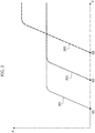
- Figure 2 is a diagram illustrating the various operating conditions of the valve 3 as a function of the electrical power supply voltage.
- the degree of opening of each of the three outlets 301, 302, 303 of the valve 3 is represented in the form of a lift A of a movable element of the valve upon variation in the electrical power supply voltage U.
- U1 Below a value U1, the valve 3 is in a completely closed condition.
- the power supply voltage U exceeds the value U1
- the first outlet 301 is progressively opened, until la condition of complete opening is reached.
- Above a voltage value U2 also in the second outlet 302 there is a progressive opening until a completely open condition is reached.
- the third outlet 303 is opened progressively until reaching a completely open condition when the power supply voltage exceeds a third value U3.
- the energizing of the solenoid of the distribution valve 3 is controlled by the electronic control unit E which may be the electronic control unit controlling the operation of the engine 2.
- the electronic control unit E can also provide control of the electric motor driving the pump 5, in the event that said pump is driven by an electric motor.
- two temperature sensors 605, 606 are provided in the conduit 109, respectively upstream and downstream from the tank 6.
- the output signals of the temperature sensors 605, 606 are sent to the electronic control unit E.
- the cooling system furthermore comprises at least one sensor 11 of the temperature of the coolant leaving the engine.
- the electronic control unit E is programmed so that, after a start of the internal combustion engine, a number of different operating phases are actuated in succession upon increasing of the temperature value of the coolant as detected by the sensor 11.
- the electronically controlled distribution valve is maintained in its closed condition, so that the coolant leaving the engine 2 immediately after the start of the engine flows entirely from the conduit 102 to the conduit 109, causing the heat exchanger 4 to be fed with the quantity of relatively warm coolant previously stored in the thermally insulated tank 6.
- the tank 6 is typically able to maintain the temperature of the coolant stored in it at a value higher than the ambient temperature, even during prolonged stops of the motor-vehicle with the engine inactive. As noted above, when the engine is started, the coolant leaving the engine 2, still relatively cold, is taken entirely to the tank 6, which is therefore emptied of the warm coolant previously stored therein. The warm coolant stored in the tank 6 is therefore fed to the heat exchanger 4.
- the heat exchanger functions as a heater of the lubricating oil and the quantity of warm liquid previously stored in the tank 6 makes it possible to accelerate the warm-up phase of the engine oil so as to reduce the time needed to bring the oil up to the ideal temperature in order to minimize engine frictions and, consequently, fuel consumption.
- the aforesaid first phase in which the tank 6 is emptied of the warm liquid previously contained therein may have a duration on the order of 20 seconds.
- the electronic control unit E is programmed to compare the temperature values coming from the temperature sensors 605, 606. When the control unit detects that these temperature values are identical within a predetermined tolerance margin, it deduces that the entire quantity of relatively warm coolant previously stored in the tank 6 has left the tank. This condition is considered to be the conclusion of the first operating phase of the system.
- the electronic control unit E triggers switching of the valve 3 from the closed condition to the aforesaid first opened condition, in which only the first outlet 301 communicates with the inlet 300 of the valve.
- this condition basically the entire flow of the coolant leaving the engine 2 flows from the conduit 102 into the conduit 103. Therefore, the entire flow of the coolant leaving the engine, also in this second operating phase, is directed to the heat exchanger 4 which in this phase acts as a heater of the lubricating oil, so as to allow reaching the ideal operating temperature of the oil as quickly as possible.
- the reaching of the end of this second operating phase can be detected as an exceeding of a predetermined threshold value detected by the temperature sensor 11.
- the electronic control unit E triggers switching of the valve 3 to a second opened condition, in which only the outlets 301 and 302 communicate with the inlet 300.
- a portion of the coolant coming from the conduit 102 continues to be fed to the heat exchanger 4, which will thus maintain the temperature of the engine lubricating oil at the desired value, as the the engine warms-up, while another portion of the coolant flows in the conduit 110, to activate the heater 8 of the passenger compartment.
- a third operating phase which can be initiated when the temperature value detected by the sensor 11 exceeds a second threshold value greater than the first threshold value, the valve 3 is switched to a third opened condition, in which all three outlets 301, 302, 303 communicate with the inlet 300.
- the coolant of the engine is also fed to the radiator 9 of the motor vehicle, where it is cooled prior to returning to the engine 2.
- the constricted cross-section 7 in the conduit 109 ensures that the coolant 102 is taken at least for the most part to the outlet 301 and/or to the outlet 302 and/or to the outlet 303, when the valve 3 is in one of its opened conditions.
- the electronic control unit E is designed to receive a signal indicative of a switch-off command of the engine and consequently to switch the valve 3 to its closed condition, so as to direct the entire flow of the coolant leaving the engine to the tank 6.
- the electronic control unit E will be able to detect the complete filling of the tank 6 with warm coolant, by checking that the temperature values detected by the sensors 605, 606 are substantially identical. Once reaching of this condition is detected, the electronic control unit E can enable the actual shutdown of the engine.
- the phase of filling the tank 6 with warm coolant can be activated even after the actual shutdown of the engine, since even when the engine is shut down the electronic control unit E can trigger the activation of the electric motor driving the pump 5.
- the pump is controlled by the engine 2, it is necessary to carry out the phase of filling the tank 6 with warm liquid before the engine is actually shut down.
- the constricted cross-section 7 in the conduit 109 enables a proper operation of the system without the need to provide the complication of an intercepting valve in the conduit 109.
- the same result can be achieved by arranging, in place of the constricted cross-section 7 in the conduit 109, a labyrinth pathway (not shown).
- the labyrinth pathway can be comprised, for example, of a tubing arranged in a winding course directly around the wall of the tank 6, on its outside.
Landscapes
- Engineering & Computer Science (AREA)
- Mechanical Engineering (AREA)
- General Engineering & Computer Science (AREA)
- Chemical & Material Sciences (AREA)
- Combustion & Propulsion (AREA)
- Life Sciences & Earth Sciences (AREA)
- Atmospheric Sciences (AREA)
- Lubrication Of Internal Combustion Engines (AREA)
Claims (14)
- Système de refroidissement pour un moteur à combustion interne de véhicule automobile, ledit système comprenant :- un circuit (1) pour un liquide de refroidissement de moteur, comportant une partie de circuit intérieure (100) interne au moteur (2) et une partie de circuit extérieure (101) externe au moteur (2),- un réservoir thermiquement isolé (6) pour le liquide de refroidissement de moteur, relié à ladite partie extérieure (101) du circuit de refroidissement (1) et adapté pour maintenir une quantité déterminée de liquide de refroidissement à une température supérieure à la température ambiante lorsque le moteur (2) est inactif, de manière à permettre à ladite quantité de liquide de refroidissement à une température supérieure à la température ambiante d'être utilisée après un démarrage ultérieur du moteur (2), pendant une phase de réchauffage du moteur,- ladite partie de circuit extérieure (101) comportant en outre :- une pompe (5) pour activer la circulation du liquide de refroidissement dans le circuit (1),- un refroidisseur d'huile (4) pour refroidir l'huile de lubrification de moteur,- un dispositif de chauffage (8) pour chauffer l'habitacle,- un radiateur (9) pour refroidir le liquide de refroidissement,- une vanne de distribution à commande électronique (3) pour commander l'écoulement de liquide de refroidissement dans la partie de circuit extérieure (101), de manière à diriger cet écoulement vers le refroidisseur (4) d'huile de lubrification et/ou vers le dispositif de chauffage (8) d'habitacle et/ou vers le radiateur (9), et- une unité de commande électronique (E) pour commander l'état de fonctionnement de ladite vanne de distribution à commande électronique (3) en fonction d'un ou de plusieurs paramètre(s) de fonctionnement comportant au moins une valeur détectée de la température du liquide de refroidissement,- où ladite vanne de distribution à commande électronique (3) a une entrée (300) reliée à un premier conduit (102) fournissant le liquide de refroidissement sortant du moteur (2),ledit système étant caractérisé en ce que :- ledit réservoir thermiquement isolé (6) est placé dans un deuxième conduit (109) reliant ledit premier conduit (102) à une entrée (401) dudit refroidisseur (4) d'huile de lubrification de moteur,- ladite vanne de distribution à commande électronique (3) comprend :- une première sortie (301) reliée à ladite entrée (401) du refroidisseur (4) d'huile de lubrification de moteur,- une deuxième sortie (302) reliée à une entrée (801) dudit dispositif de chauffage (8) d'habitacle, et- une troisième sortie (303) reliée à une entrée (901) dudit radiateur (9),- ladite vanne de distribution à commande électronique (3) pouvant être sélectivement commutée vers l'un des états de fonctionnement suivants :- un état fermé, dans lequel toutes lesdites première, deuxième et troisième sorties (301, 302, 303) sont isolées par rapport à ladite entrée (300) de la vanne (3),- un premier état ouvert, dans lequel seule ladite première sortie (301) communique avec l'entrée (300) de la vanne (3),- un deuxième état ouvert, dans lequel seules lesdites première et deuxième sorties (301, 302) communiquent avec l'entrée (300) de la vanne (3), et- un troisième état ouvert, dans lequel toutes lesdites première, deuxième et troisième sorties (301, 302, 303) communiquent avec ladite entrée (300) de la vanne (3),- ladite unité de commande électronique (E) étant programmée de sorte que, après le démarrage du moteur à combustion interne (2), les phases de fonctionnement suivantes sont actionnées en séquence, à mesure que la température détectée du liquide de refroidissement de moteur augmente :- une première phase dans laquelle la vanne de distribution à commande électronique (3) est maintenue dans son état fermé, de sorte que le liquide de refroidissement quittant le moteur (2) s'écoule entièrement à partir dudit premier conduit (102) vers ledit deuxième conduit (109), amenant la quantité de liquide de refroidissement préalablement stockée dans le réservoir thermiquement isolé (6) à être introduite dans le refroidisseur (4) d'huile de lubrification de moteur,- une deuxième phase dans laquelle la vanne de distribution à commande électronique (3) est maintenue dans son premier état ouvert, de sorte que le liquide de refroidissement quittant le moteur soit toujours introduit uniquement dans le refroidisseur (4) d'huile de lubrification de moteur,- une troisième phase dans laquelle la vanne de distribution à commande électronique (3) est maintenue dans son deuxième état ouvert, de sorte que le liquide de refroidissement quittant le moteur soit introduit à la fois dans le refroidisseur (4) d'huile de lubrification de moteur et dans le dispositif de chauffage (8) d'habitacle, et- une quatrième phase dans laquelle la vanne de distribution à commande électronique (3) est maintenue dans son troisième état ouvert, de sorte que le liquide de refroidissement quittant le moteur (2) soit introduit à la fois dans le refroidisseur (4) d'huile de lubrification de moteur et dans le dispositif de chauffage (8) d'habitacle et dans le radiateur (9).
- Système de refroidissement selon la revendication 1, caractérisé en ce que l'entrée (601) dudit réservoir thermiquement isolé (6) communique avec ledit premier conduit (102) à travers un passage ayant une section transversale limitée (7) et/ou à travers un trajet en labyrinthe, de sorte que, lorsque la vanne de distribution à commande électronique (3) est dans l'un de ses états ouverts, le liquide de refroidissement quittant le moteur tende à s'écouler vers les sorties de la vanne (3), plutôt que vers ledit réservoir thermiquement isolé (6).
- Système de refroidissement selon la revendication 1, caractérisé en ce que deux capteurs de température (605, 606) sont prévus dans ledit deuxième conduit (109), agencés respectivement en amont et en aval du réservoir thermiquement isolé (6), et l'unité de commande électronique (E) est configurée pour recevoir les signaux de sortie provenant desdits capteurs de température (605, 606) et pour provoquer une commutation de ladite première phase de fonctionnement vers ladite deuxième phase de fonctionnement lorsque les valeurs de température détectées par lesdits capteurs (605, 606) deviennent sensiblement identiques.
- Système de refroidissement selon la revendication 1, caractérisé en ce que ladite unité de commande électronique (E) est configurée pour provoquer une commutation de ladite deuxième phase de fonctionnement vers ladite troisième phase de fonctionnement lorsque ladite valeur détectée de la température de liquide de refroidissement dépasse une première valeur seuil, et pour provoquer une commutation de ladite troisième phase de fonctionnement vers ladite quatrième phase de fonctionnement lorsque la valeur détectée de la température du liquide de refroidissement dépasse une deuxième valeur seuil, supérieure à ladite première valeur seuil.
- Système de refroidissement selon la revendication 1, caractérisé en ce que l'unité de commande électronique (E) est configurée pour recevoir un signal indiquant une instruction d'arrêt de moteur pour arrêter le moteur à combustion interne (2), ainsi que pour provoquer par conséquent la commutation de la vanne de distribution à commande électronique (3) vers son état fermé, de sorte que le liquide de refroidissement chaud quittant le moteur à combustion interne (2) soit dirigé vers ledit réservoir thermiquement isolé (6).
- Système de refroidissement selon la revendication 5, caractérisé en ce que la pompe (5) est actionnée par le moteur à combustion interne (2) et ladite unité de commande électronique (E) est configurée pour permettre l'arrêt du moteur uniquement après la détection d'un remplissage du réservoir thermiquement isolé (6) avec le liquide de refroidissement chaud sortant du moteur (2).
- Système de refroidissement selon la revendication 5, caractérisé en ce que la pompe (5) est actionnée électriquement, et ladite commutation de la vanne (3) vers l'état fermé pour obtenir un remplissage du réservoir thermiquement isolé (6) avec le liquide de refroidissement chaud est déclenchée après l'arrêt du moteur à combustion interne.
- Système de refroidissement selon la revendication 2, caractérisé en ce que l'entrée (601) du réservoir thermiquement isolé (6) communique avec le premier conduit (102) à travers un trajet en labyrinthe défini par un conduit agencé dans un trajet d'enroulement autour du corps du réservoir thermiquement isolé (6).
- Procédé de commande d'un système de refroidissement d'un moteur à combustion interne d'un véhicule automobile, dans lequel ledit système comprend :- un circuit (1) pour un liquide de refroidissement de moteur, comportant une partie de circuit intérieure (100) interne au moteur (2) et une partie de circuit extérieure (101) externe au moteur (2),- un réservoir thermiquement isolé (6) pour le liquide de refroidissement de moteur, relié à ladite partie extérieure (101) du circuit de refroidissement (1) et adapté pour maintenir une quantité déterminée de liquide de refroidissement à une température supérieure à la température ambiante lorsque le moteur (2) est inactif, pour permettre l'utilisation de cette quantité de liquide de refroidissement à une température supérieure à la température ambiante après un démarrage ultérieur du moteur (2), pendant la phase de réchauffage du moteur,- ladite partie de circuit extérieure (101) comportant en outre :- une pompe (5) pour activer la circulation du liquide de refroidissement dans le circuit (1),- un refroidisseur d'huile (4) pour refroidir l'huile de lubrification de moteur,- un dispositif de chauffage (8) pour chauffer l'habitacle,- un radiateur (9) pour refroidir le liquide de refroidissement,- une vanne de distribution à commande électronique (3) pour commander l'écoulement de liquide de refroidissement dans la partie de circuit extérieure (101), de manière à diriger cet écoulement vers le refroidisseur (4) d'huile de lubrification et/ou vers le dispositif de chauffage (8) d'habitacle et/ou vers le radiateur (9), et- l'état de fonctionnement de ladite vanne de distribution à commande électronique (3) étant commandé en fonction d'un ou de plusieurs paramètre(s) de fonctionnement, comportant au moins une valeur détectée de la température du liquide de refroidissement,- où ladite vanne de distribution à commande électronique (3) a une entrée (300) reliée à un premier conduit (102) fournissant le liquide de refroidissement sortant du moteur (2),ledit procédé étant caractérisé en ce que :- ledit réservoir thermiquement isolé (6) est placé dans un deuxième conduit (109) reliant ledit premier conduit (102) à une entrée (401) dudit refroidisseur (4) d'huile de lubrification de moteur,- ladite vanne de distribution à commande électronique (3) comprend :- une première sortie (301) reliée à ladite entrée (401) du refroidisseur (4) d'huile de lubrification de moteur,- une deuxième sortie (302) reliée à une entrée (801) dudit dispositif de chauffage (8) d'habitacle, et- une troisième sortie (303) reliée à une entrée (901) dudit radiateur (9),- ladite vanne de distribution à commande électronique (3) pouvant être sélectivement commutée vers l'un des états de fonctionnement suivants :- un état fermé, dans lequel toutes lesdites première, deuxième et troisième sorties (301, 302, 303) sont isolées par rapport à ladite entrée (300) de la vanne (3),- un premier état ouvert, dans lequel seule ladite première sortie (301) communique avec l'entrée (300) de la vanne (3),- un deuxième état ouvert, dans lequel seules lesdites première et deuxième sorties (301, 302) communiquent avec l'entrée (300) de la vanne (3), et- un troisième état ouvert, dans lequel toutes lesdites première, deuxième et troisième sorties (301, 302, 303) communiquent avec ladite entrée (300) de la vanne (3),- après le démarrage du moteur à combustion interne (2), les phases de fonctionnement suivantes sont actionnées successivement, à mesure que la température détectée du liquide de refroidissement de moteur augmente :- une première phase dans laquelle la vanne de distribution à commande électronique (3) est maintenue dans son état fermé, de sorte que le liquide de refroidissement quittant le moteur (2) s'écoule entièrement à partir dudit premier conduit (102) vers ledit deuxième conduit (109), amenant la quantité de liquide de refroidissement préalablement stockée dans le réservoir thermiquement isolé (6) à être introduite dans le refroidisseur (4) d'huile de lubrification de moteur,- une deuxième phase dans laquelle la vanne de distribution à commande électronique (3) est maintenue dans son premier état ouvert, de sorte que le liquide de refroidissement quittant le moteur soit toujours introduit uniquement dans le refroidisseur (4) d'huile de lubrification de moteur,- une troisième phase dans laquelle la vanne de distribution à commande électronique (3) est maintenue dans son deuxième état ouvert, de sorte que le liquide de refroidissement quittant le moteur soit introduit à la fois dans le refroidisseur (4) d'huile de lubrification de moteur et dans le dispositif de chauffage (8) d'habitacle, et- une quatrième phase dans laquelle la vanne de distribution à commande électronique (3) est maintenue dans son troisième état ouvert, de sorte que le liquide de refroidissement quittant le moteur (2) soit introduit à la fois dans le refroidisseur (4) d'huile de lubrification de moteur et dans le dispositif de chauffage (8) d'habitacle et dans le radiateur (9).
- Procédé selon la revendication 9, caractérisé en ce que deux capteurs de température (605, 606) sont prévus dans ledit deuxième conduit (109), agencés respectivement en amont et en aval du réservoir thermiquement isolé (6), et une commutation de ladite première phase de fonctionnement vers ladite deuxième phase de fonctionnement est déclenchée lorsque les valeurs de température détectées par lesdits capteurs (605, 606) deviennent sensiblement identiques.
- Procédé selon la revendication 9 ou 10, caractérisé en ce que ladite unité de commande électronique (E) est configurée pour provoquer une commutation de ladite deuxième phase de fonctionnement vers ladite troisième phase de fonctionnement lorsque ladite valeur détectée de la température de liquide de refroidissement dépasse une première valeur seuil, et pour provoquer une commutation de ladite troisième phase de fonctionnement vers ladite quatrième phase de fonctionnement lorsque la valeur détectée de la température du liquide de refroidissement dépasse une deuxième valeur seuil, supérieure à ladite première valeur seuil.
- Procédé selon la revendication 9, caractérisé en ce que lorsqu'une instruction pour arrêter le moteur à combustion interne (2) est reçue, le liquide de refroidissement chaud quittant le moteur à combustion interne (2) est acheminé jusqu'audit réservoir thermiquement isolé (6).
- Procédé selon la revendication 12, caractérisé en ce que la pompe (5) est actionnée par le moteur à combustion interne (2) et en ce que l'arrêt du moteur n'est autorisé qu'après avoir détecté un remplissage du réservoir thermiquement isolé (6) avec le liquide de refroidissement chaud quittant le moteur (2).
- Procédé selon la revendication 12, caractérisé en ce que la pompe (5) est actionnée électriquement et en ce que le réservoir thermiquement isolé (6) est rempli du liquide de refroidissement chaud après l'arrêt du moteur à combustion interne.
Priority Applications (2)
| Application Number | Priority Date | Filing Date | Title |
|---|---|---|---|
| EP16169784.2A EP3246541B1 (fr) | 2016-05-16 | 2016-05-16 | Système de refroidissement pour un moteur à combustion interne d'un véhicule automobile |
| US15/438,808 US10030551B2 (en) | 2016-05-16 | 2017-02-22 | Cooling system for an internal combustion engine of a motor vehicle |
Applications Claiming Priority (1)
| Application Number | Priority Date | Filing Date | Title |
|---|---|---|---|
| EP16169784.2A EP3246541B1 (fr) | 2016-05-16 | 2016-05-16 | Système de refroidissement pour un moteur à combustion interne d'un véhicule automobile |
Publications (2)
| Publication Number | Publication Date |
|---|---|
| EP3246541A1 EP3246541A1 (fr) | 2017-11-22 |
| EP3246541B1 true EP3246541B1 (fr) | 2018-07-18 |
Family
ID=56112821
Family Applications (1)
| Application Number | Title | Priority Date | Filing Date |
|---|---|---|---|
| EP16169784.2A Active EP3246541B1 (fr) | 2016-05-16 | 2016-05-16 | Système de refroidissement pour un moteur à combustion interne d'un véhicule automobile |
Country Status (2)
| Country | Link |
|---|---|
| US (1) | US10030551B2 (fr) |
| EP (1) | EP3246541B1 (fr) |
Cited By (1)
| Publication number | Priority date | Publication date | Assignee | Title |
|---|---|---|---|---|
| EP3623183A1 (fr) | 2018-09-11 | 2020-03-18 | C.R.F. Società Consortile per Azioni | Système de gestion thermique des composants d'un véhicule hybride |
Families Citing this family (5)
| Publication number | Priority date | Publication date | Assignee | Title |
|---|---|---|---|---|
| EP3369907B1 (fr) | 2017-03-03 | 2019-04-10 | C.R.F. Società Consortile per Azioni | Système de refroidissement d'un moteur à combustion interne d'un véhicule automobile |
| CN108678850B (zh) * | 2018-07-16 | 2023-10-24 | 河北工业大学 | 使用润滑油的智能缸套热管理系统 |
| CN111042891B (zh) * | 2019-12-31 | 2021-08-03 | 宁波吉利罗佑发动机零部件有限公司 | 增程式润滑管理系统、润滑管理方法及车辆 |
| CN115013114A (zh) * | 2022-06-13 | 2022-09-06 | 潍柴动力股份有限公司 | 一种发动机预加热系统及方法 |
| CN118572265B (zh) * | 2024-08-01 | 2024-11-19 | 比亚迪股份有限公司 | 充电站的电池热管理系统、充电站和控制方法 |
Family Cites Families (18)
| Publication number | Priority date | Publication date | Assignee | Title |
|---|---|---|---|---|
| JP2003322019A (ja) | 2002-04-30 | 2003-11-14 | Denso Corp | 車両用内燃機関の冷却系装置 |
| US2401510A (en) | 1944-03-25 | 1946-06-04 | Rowley Kennard Albert | Engine cooling system |
| JPS6183405A (ja) * | 1984-09-29 | 1986-04-28 | Nissan Motor Co Ltd | 潤滑油冷却装置 |
| DE4136910C2 (de) | 1991-11-09 | 1994-10-20 | Schatz Oskar | Verfahren zur schnellen Einstellung der Betriebstemperatur einer Masse durch einen fließ- oder rieselfähigen Wärmeträger, insbesondere zur Schnellaufheizung eines Kraftfahrzeugmotors beim Kaltstart |
| JP3353236B2 (ja) | 1995-02-24 | 2002-12-03 | 株式会社日本自動車部品総合研究所 | 内燃機関の冷却装置 |
| JP3525538B2 (ja) * | 1995-03-08 | 2004-05-10 | 株式会社デンソー | 車両用内燃機関の冷却系装置 |
| JP3843499B2 (ja) | 1996-08-30 | 2006-11-08 | 株式会社デンソー | 内燃機関の冷却水回路 |
| US5896833A (en) * | 1996-08-30 | 1999-04-27 | Denso Corporation | Cooling water circuit system and cooling water control valve |
| JPH10309933A (ja) | 1997-05-13 | 1998-11-24 | Denso Corp | 車両用暖房装置 |
| US6520136B2 (en) * | 2000-09-13 | 2003-02-18 | Toyota Jidosha Kabushiki Kaisha | Warm-up control device for internal-combustion engine and warm-up control method |
| JP2002266679A (ja) | 2001-03-06 | 2002-09-18 | Denso Corp | 内燃機関用制御装置 |
| GB0310120D0 (en) * | 2003-05-02 | 2003-06-04 | Ford Global Tech Llc | Engine cooling systems |
| DE10344018B4 (de) | 2003-09-15 | 2016-12-22 | Mahle International Gmbh | Kühlsystem eingerichtet für einen Verbrennungsmotor mit einem Heißwasserspeicher |
| FR2899647B1 (fr) * | 2006-04-05 | 2011-09-16 | Renault Sas | Systeme et procede de controle de la temperature d'un moteur suralimente et comportant un radiateur d'air de suralimentation |
| JP2008082225A (ja) | 2006-09-27 | 2008-04-10 | Mazda Motor Corp | エンジンの冷却装置 |
| US7533636B2 (en) * | 2007-04-30 | 2009-05-19 | General Electric Company | System, method, and computer readable media for controlling cooling in a diesel fueled power generation unit |
| JP5189461B2 (ja) | 2008-11-05 | 2013-04-24 | トヨタ自動車株式会社 | 内燃機関の冷却装置 |
| DE102011084632B4 (de) * | 2011-10-17 | 2015-03-05 | Ford Global Technologies, Llc | Verfahren zum Erwärmen einer Brennkraftmaschine und Brennkraftmaschine zur Durchführung eines derartigen Verfahrens |
-
2016
- 2016-05-16 EP EP16169784.2A patent/EP3246541B1/fr active Active
-
2017
- 2017-02-22 US US15/438,808 patent/US10030551B2/en active Active
Non-Patent Citations (1)
| Title |
|---|
| None * |
Cited By (2)
| Publication number | Priority date | Publication date | Assignee | Title |
|---|---|---|---|---|
| EP3623183A1 (fr) | 2018-09-11 | 2020-03-18 | C.R.F. Società Consortile per Azioni | Système de gestion thermique des composants d'un véhicule hybride |
| US11091007B2 (en) | 2018-09-11 | 2021-08-17 | C.R.F. Societè Consortile per Azioni | System for thermal management of the components of a hybrid vehicle |
Also Published As
| Publication number | Publication date |
|---|---|
| US20170328246A1 (en) | 2017-11-16 |
| EP3246541A1 (fr) | 2017-11-22 |
| US10030551B2 (en) | 2018-07-24 |
Similar Documents
| Publication | Publication Date | Title |
|---|---|---|
| US10030551B2 (en) | Cooling system for an internal combustion engine of a motor vehicle | |
| EP3369907B1 (fr) | Système de refroidissement d'un moteur à combustion interne d'un véhicule automobile | |
| KR100305358B1 (ko) | 내연기관을위한냉각시스템 | |
| EP2864607B1 (fr) | Dispositif de commande d'écoulement de fluide | |
| US7721683B2 (en) | Integrated engine thermal management | |
| US8291870B2 (en) | Cooling systems | |
| US6966278B2 (en) | Electronically controlled thermostat | |
| CN102529638B (zh) | 车辆加热系统 | |
| US9452660B2 (en) | Valve system configurations for warming and cooling transmission fluid | |
| US20130263802A1 (en) | Engine cooling system, electronic thermostat control system and control method for the same | |
| CN109790773A (zh) | 电动冷却液泵 | |
| GB2540401A (en) | A cooling assembly | |
| CN103867683A (zh) | 用于传动液的贮存器 | |
| JP2012102639A (ja) | エンジンの冷却装置 | |
| US6471134B2 (en) | Thermostatic device having two regulating conditions and two thermostatic elements | |
| CN106460613A (zh) | 加热用于机动车内水成操作液体的存储容器的系统以及加热存储容器的方法 | |
| US6595432B2 (en) | Heating system for heating the passenger compartment of an automobile | |
| CN103306800B (zh) | 车辆用内燃机的冷却设备 | |
| JP4608539B2 (ja) | クーラントによって冷却される内燃機関用のクーラント回路 | |
| US6929189B2 (en) | Thermostat device and temperature control method and system for engine coolant | |
| JP2016114224A (ja) | サーモスタット及びサーモスタットの制御方法 | |
| KR20190142954A (ko) | 써모스탯 및 이를 포함하는 냉각 시스템 | |
| US12007796B2 (en) | Thermostatic valve | |
| SE1151136A1 (sv) | System för reglering av vätskeflödet i ett fordon | |
| KR20180062801A (ko) | 선박의 연료공급시스템 |
Legal Events
| Date | Code | Title | Description |
|---|---|---|---|
| PUAI | Public reference made under article 153(3) epc to a published international application that has entered the european phase |
Free format text: ORIGINAL CODE: 0009012 |
|
| STAA | Information on the status of an ep patent application or granted ep patent |
Free format text: STATUS: THE APPLICATION HAS BEEN PUBLISHED |
|
| STAA | Information on the status of an ep patent application or granted ep patent |
Free format text: STATUS: REQUEST FOR EXAMINATION WAS MADE |
|
| AK | Designated contracting states |
Kind code of ref document: A1 Designated state(s): AL AT BE BG CH CY CZ DE DK EE ES FI FR GB GR HR HU IE IS IT LI LT LU LV MC MK MT NL NO PL PT RO RS SE SI SK SM TR |
|
| AX | Request for extension of the european patent |
Extension state: BA ME |
|
| 17P | Request for examination filed |
Effective date: 20171026 |
|
| RBV | Designated contracting states (corrected) |
Designated state(s): AL AT BE BG CH CY CZ DE DK EE ES FI FR GB GR HR HU IE IS IT LI LT LU LV MC MK MT NL NO PL PT RO RS SE SI SK SM TR |
|
| RIC1 | Information provided on ipc code assigned before grant |
Ipc: F01P 11/20 20060101ALI20171215BHEP Ipc: F01P 7/16 20060101AFI20171215BHEP |
|
| GRAP | Despatch of communication of intention to grant a patent |
Free format text: ORIGINAL CODE: EPIDOSNIGR1 |
|
| STAA | Information on the status of an ep patent application or granted ep patent |
Free format text: STATUS: GRANT OF PATENT IS INTENDED |
|
| INTG | Intention to grant announced |
Effective date: 20180214 |
|
| GRAS | Grant fee paid |
Free format text: ORIGINAL CODE: EPIDOSNIGR3 |
|
| GRAA | (expected) grant |
Free format text: ORIGINAL CODE: 0009210 |
|
| STAA | Information on the status of an ep patent application or granted ep patent |
Free format text: STATUS: THE PATENT HAS BEEN GRANTED |
|
| AK | Designated contracting states |
Kind code of ref document: B1 Designated state(s): AL AT BE BG CH CY CZ DE DK EE ES FI FR GB GR HR HU IE IS IT LI LT LU LV MC MK MT NL NO PL PT RO RS SE SI SK SM TR |
|
| REG | Reference to a national code |
Ref country code: GB Ref legal event code: FG4D |
|
| REG | Reference to a national code |
Ref country code: CH Ref legal event code: EP |
|
| REG | Reference to a national code |
Ref country code: IE Ref legal event code: FG4D |
|
| REG | Reference to a national code |
Ref country code: AT Ref legal event code: REF Ref document number: 1019620 Country of ref document: AT Kind code of ref document: T Effective date: 20180815 |
|
| REG | Reference to a national code |
Ref country code: DE Ref legal event code: R096 Ref document number: 602016004072 Country of ref document: DE |
|
| REG | Reference to a national code |
Ref country code: NL Ref legal event code: MP Effective date: 20180718 |
|
| REG | Reference to a national code |
Ref country code: LT Ref legal event code: MG4D |
|
| REG | Reference to a national code |
Ref country code: AT Ref legal event code: MK05 Ref document number: 1019620 Country of ref document: AT Kind code of ref document: T Effective date: 20180718 |
|
| PG25 | Lapsed in a contracting state [announced via postgrant information from national office to epo] |
Ref country code: NL Free format text: LAPSE BECAUSE OF FAILURE TO SUBMIT A TRANSLATION OF THE DESCRIPTION OR TO PAY THE FEE WITHIN THE PRESCRIBED TIME-LIMIT Effective date: 20180718 |
|
| PG25 | Lapsed in a contracting state [announced via postgrant information from national office to epo] |
Ref country code: PL Free format text: LAPSE BECAUSE OF FAILURE TO SUBMIT A TRANSLATION OF THE DESCRIPTION OR TO PAY THE FEE WITHIN THE PRESCRIBED TIME-LIMIT Effective date: 20180718 Ref country code: RS Free format text: LAPSE BECAUSE OF FAILURE TO SUBMIT A TRANSLATION OF THE DESCRIPTION OR TO PAY THE FEE WITHIN THE PRESCRIBED TIME-LIMIT Effective date: 20180718 Ref country code: LT Free format text: LAPSE BECAUSE OF FAILURE TO SUBMIT A TRANSLATION OF THE DESCRIPTION OR TO PAY THE FEE WITHIN THE PRESCRIBED TIME-LIMIT Effective date: 20180718 Ref country code: SE Free format text: LAPSE BECAUSE OF FAILURE TO SUBMIT A TRANSLATION OF THE DESCRIPTION OR TO PAY THE FEE WITHIN THE PRESCRIBED TIME-LIMIT Effective date: 20180718 Ref country code: BG Free format text: LAPSE BECAUSE OF FAILURE TO SUBMIT A TRANSLATION OF THE DESCRIPTION OR TO PAY THE FEE WITHIN THE PRESCRIBED TIME-LIMIT Effective date: 20181018 Ref country code: GR Free format text: LAPSE BECAUSE OF FAILURE TO SUBMIT A TRANSLATION OF THE DESCRIPTION OR TO PAY THE FEE WITHIN THE PRESCRIBED TIME-LIMIT Effective date: 20181019 Ref country code: FI Free format text: LAPSE BECAUSE OF FAILURE TO SUBMIT A TRANSLATION OF THE DESCRIPTION OR TO PAY THE FEE WITHIN THE PRESCRIBED TIME-LIMIT Effective date: 20180718 Ref country code: AT Free format text: LAPSE BECAUSE OF FAILURE TO SUBMIT A TRANSLATION OF THE DESCRIPTION OR TO PAY THE FEE WITHIN THE PRESCRIBED TIME-LIMIT Effective date: 20180718 Ref country code: IS Free format text: LAPSE BECAUSE OF FAILURE TO SUBMIT A TRANSLATION OF THE DESCRIPTION OR TO PAY THE FEE WITHIN THE PRESCRIBED TIME-LIMIT Effective date: 20181118 Ref country code: NO Free format text: LAPSE BECAUSE OF FAILURE TO SUBMIT A TRANSLATION OF THE DESCRIPTION OR TO PAY THE FEE WITHIN THE PRESCRIBED TIME-LIMIT Effective date: 20181018 |
|
| PG25 | Lapsed in a contracting state [announced via postgrant information from national office to epo] |
Ref country code: HR Free format text: LAPSE BECAUSE OF FAILURE TO SUBMIT A TRANSLATION OF THE DESCRIPTION OR TO PAY THE FEE WITHIN THE PRESCRIBED TIME-LIMIT Effective date: 20180718 Ref country code: LV Free format text: LAPSE BECAUSE OF FAILURE TO SUBMIT A TRANSLATION OF THE DESCRIPTION OR TO PAY THE FEE WITHIN THE PRESCRIBED TIME-LIMIT Effective date: 20180718 Ref country code: AL Free format text: LAPSE BECAUSE OF FAILURE TO SUBMIT A TRANSLATION OF THE DESCRIPTION OR TO PAY THE FEE WITHIN THE PRESCRIBED TIME-LIMIT Effective date: 20180718 |
|
| REG | Reference to a national code |
Ref country code: DE Ref legal event code: R097 Ref document number: 602016004072 Country of ref document: DE |
|
| PG25 | Lapsed in a contracting state [announced via postgrant information from national office to epo] |
Ref country code: RO Free format text: LAPSE BECAUSE OF FAILURE TO SUBMIT A TRANSLATION OF THE DESCRIPTION OR TO PAY THE FEE WITHIN THE PRESCRIBED TIME-LIMIT Effective date: 20180718 Ref country code: CZ Free format text: LAPSE BECAUSE OF FAILURE TO SUBMIT A TRANSLATION OF THE DESCRIPTION OR TO PAY THE FEE WITHIN THE PRESCRIBED TIME-LIMIT Effective date: 20180718 Ref country code: EE Free format text: LAPSE BECAUSE OF FAILURE TO SUBMIT A TRANSLATION OF THE DESCRIPTION OR TO PAY THE FEE WITHIN THE PRESCRIBED TIME-LIMIT Effective date: 20180718 Ref country code: ES Free format text: LAPSE BECAUSE OF FAILURE TO SUBMIT A TRANSLATION OF THE DESCRIPTION OR TO PAY THE FEE WITHIN THE PRESCRIBED TIME-LIMIT Effective date: 20180718 |
|
| PLBE | No opposition filed within time limit |
Free format text: ORIGINAL CODE: 0009261 |
|
| STAA | Information on the status of an ep patent application or granted ep patent |
Free format text: STATUS: NO OPPOSITION FILED WITHIN TIME LIMIT |
|
| PG25 | Lapsed in a contracting state [announced via postgrant information from national office to epo] |
Ref country code: SK Free format text: LAPSE BECAUSE OF FAILURE TO SUBMIT A TRANSLATION OF THE DESCRIPTION OR TO PAY THE FEE WITHIN THE PRESCRIBED TIME-LIMIT Effective date: 20180718 Ref country code: DK Free format text: LAPSE BECAUSE OF FAILURE TO SUBMIT A TRANSLATION OF THE DESCRIPTION OR TO PAY THE FEE WITHIN THE PRESCRIBED TIME-LIMIT Effective date: 20180718 Ref country code: SM Free format text: LAPSE BECAUSE OF FAILURE TO SUBMIT A TRANSLATION OF THE DESCRIPTION OR TO PAY THE FEE WITHIN THE PRESCRIBED TIME-LIMIT Effective date: 20180718 |
|
| 26N | No opposition filed |
Effective date: 20190423 |
|
| PG25 | Lapsed in a contracting state [announced via postgrant information from national office to epo] |
Ref country code: SI Free format text: LAPSE BECAUSE OF FAILURE TO SUBMIT A TRANSLATION OF THE DESCRIPTION OR TO PAY THE FEE WITHIN THE PRESCRIBED TIME-LIMIT Effective date: 20180718 |
|
| REG | Reference to a national code |
Ref country code: CH Ref legal event code: PL |
|
| PG25 | Lapsed in a contracting state [announced via postgrant information from national office to epo] |
Ref country code: CH Free format text: LAPSE BECAUSE OF NON-PAYMENT OF DUE FEES Effective date: 20190531 Ref country code: LI Free format text: LAPSE BECAUSE OF NON-PAYMENT OF DUE FEES Effective date: 20190531 Ref country code: MC Free format text: LAPSE BECAUSE OF FAILURE TO SUBMIT A TRANSLATION OF THE DESCRIPTION OR TO PAY THE FEE WITHIN THE PRESCRIBED TIME-LIMIT Effective date: 20180718 |
|
| REG | Reference to a national code |
Ref country code: BE Ref legal event code: MM Effective date: 20190531 |
|
| PG25 | Lapsed in a contracting state [announced via postgrant information from national office to epo] |
Ref country code: LU Free format text: LAPSE BECAUSE OF NON-PAYMENT OF DUE FEES Effective date: 20190516 |
|
| PG25 | Lapsed in a contracting state [announced via postgrant information from national office to epo] |
Ref country code: TR Free format text: LAPSE BECAUSE OF FAILURE TO SUBMIT A TRANSLATION OF THE DESCRIPTION OR TO PAY THE FEE WITHIN THE PRESCRIBED TIME-LIMIT Effective date: 20180718 |
|
| PG25 | Lapsed in a contracting state [announced via postgrant information from national office to epo] |
Ref country code: IE Free format text: LAPSE BECAUSE OF NON-PAYMENT OF DUE FEES Effective date: 20190516 |
|
| PG25 | Lapsed in a contracting state [announced via postgrant information from national office to epo] |
Ref country code: BE Free format text: LAPSE BECAUSE OF NON-PAYMENT OF DUE FEES Effective date: 20190531 |
|
| PG25 | Lapsed in a contracting state [announced via postgrant information from national office to epo] |
Ref country code: PT Free format text: LAPSE BECAUSE OF FAILURE TO SUBMIT A TRANSLATION OF THE DESCRIPTION OR TO PAY THE FEE WITHIN THE PRESCRIBED TIME-LIMIT Effective date: 20181118 |
|
| GBPC | Gb: european patent ceased through non-payment of renewal fee |
Effective date: 20200516 |
|
| PG25 | Lapsed in a contracting state [announced via postgrant information from national office to epo] |
Ref country code: GB Free format text: LAPSE BECAUSE OF NON-PAYMENT OF DUE FEES Effective date: 20200516 |
|
| PG25 | Lapsed in a contracting state [announced via postgrant information from national office to epo] |
Ref country code: CY Free format text: LAPSE BECAUSE OF FAILURE TO SUBMIT A TRANSLATION OF THE DESCRIPTION OR TO PAY THE FEE WITHIN THE PRESCRIBED TIME-LIMIT Effective date: 20180718 |
|
| PG25 | Lapsed in a contracting state [announced via postgrant information from national office to epo] |
Ref country code: HU Free format text: LAPSE BECAUSE OF FAILURE TO SUBMIT A TRANSLATION OF THE DESCRIPTION OR TO PAY THE FEE WITHIN THE PRESCRIBED TIME-LIMIT; INVALID AB INITIO Effective date: 20160516 Ref country code: MT Free format text: LAPSE BECAUSE OF FAILURE TO SUBMIT A TRANSLATION OF THE DESCRIPTION OR TO PAY THE FEE WITHIN THE PRESCRIBED TIME-LIMIT Effective date: 20180718 |
|
| PG25 | Lapsed in a contracting state [announced via postgrant information from national office to epo] |
Ref country code: MK Free format text: LAPSE BECAUSE OF FAILURE TO SUBMIT A TRANSLATION OF THE DESCRIPTION OR TO PAY THE FEE WITHIN THE PRESCRIBED TIME-LIMIT Effective date: 20180718 |
|
| PGFP | Annual fee paid to national office [announced via postgrant information from national office to epo] |
Ref country code: DE Payment date: 20250428 Year of fee payment: 10 |
|
| PGFP | Annual fee paid to national office [announced via postgrant information from national office to epo] |
Ref country code: IT Payment date: 20250430 Year of fee payment: 10 |
|
| PGFP | Annual fee paid to national office [announced via postgrant information from national office to epo] |
Ref country code: FR Payment date: 20250425 Year of fee payment: 10 |