EP3246543B1 - Mécanisme à piston et manivelle à double biellette pour moteur à combustion interne - Google Patents
Mécanisme à piston et manivelle à double biellette pour moteur à combustion interne Download PDFInfo
- Publication number
- EP3246543B1 EP3246543B1 EP15877824.1A EP15877824A EP3246543B1 EP 3246543 B1 EP3246543 B1 EP 3246543B1 EP 15877824 A EP15877824 A EP 15877824A EP 3246543 B1 EP3246543 B1 EP 3246543B1
- Authority
- EP
- European Patent Office
- Prior art keywords
- link
- crank
- hole
- pin
- end side
- Prior art date
- Legal status (The legal status is an assumption and is not a legal conclusion. Google has not performed a legal analysis and makes no representation as to the accuracy of the status listed.)
- Active
Links
Images


Classifications
-
- F—MECHANICAL ENGINEERING; LIGHTING; HEATING; WEAPONS; BLASTING
- F02—COMBUSTION ENGINES; HOT-GAS OR COMBUSTION-PRODUCT ENGINE PLANTS
- F02B—INTERNAL-COMBUSTION PISTON ENGINES; COMBUSTION ENGINES IN GENERAL
- F02B75/00—Other engines
- F02B75/04—Engines with variable distances between pistons at top dead-centre positions and cylinder heads
- F02B75/045—Engines with variable distances between pistons at top dead-centre positions and cylinder heads by means of a variable connecting rod length
-
- F—MECHANICAL ENGINEERING; LIGHTING; HEATING; WEAPONS; BLASTING
- F02—COMBUSTION ENGINES; HOT-GAS OR COMBUSTION-PRODUCT ENGINE PLANTS
- F02B—INTERNAL-COMBUSTION PISTON ENGINES; COMBUSTION ENGINES IN GENERAL
- F02B75/00—Other engines
- F02B75/04—Engines with variable distances between pistons at top dead-centre positions and cylinder heads
-
- F—MECHANICAL ENGINEERING; LIGHTING; HEATING; WEAPONS; BLASTING
- F01—MACHINES OR ENGINES IN GENERAL; ENGINE PLANTS IN GENERAL; STEAM ENGINES
- F01M—LUBRICATING OF MACHINES OR ENGINES IN GENERAL; LUBRICATING INTERNAL COMBUSTION ENGINES; CRANKCASE VENTILATING
- F01M1/00—Pressure lubrication
- F01M1/06—Lubricating systems characterised by the provision therein of crankshafts or connecting rods with lubricant passageways, e.g. bores
-
- F—MECHANICAL ENGINEERING; LIGHTING; HEATING; WEAPONS; BLASTING
- F02—COMBUSTION ENGINES; HOT-GAS OR COMBUSTION-PRODUCT ENGINE PLANTS
- F02B—INTERNAL-COMBUSTION PISTON ENGINES; COMBUSTION ENGINES IN GENERAL
- F02B75/00—Other engines
- F02B75/32—Engines characterised by connections between pistons and main shafts and not specific to preceding main groups
-
- F—MECHANICAL ENGINEERING; LIGHTING; HEATING; WEAPONS; BLASTING
- F16—ENGINEERING ELEMENTS AND UNITS; GENERAL MEASURES FOR PRODUCING AND MAINTAINING EFFECTIVE FUNCTIONING OF MACHINES OR INSTALLATIONS; THERMAL INSULATION IN GENERAL
- F16C—SHAFTS; FLEXIBLE SHAFTS; ELEMENTS OR CRANKSHAFT MECHANISMS; ROTARY BODIES OTHER THAN GEARING ELEMENTS; BEARINGS
- F16C11/00—Pivots; Pivotal connections
- F16C11/02—Trunnions; Crank-pins
-
- F—MECHANICAL ENGINEERING; LIGHTING; HEATING; WEAPONS; BLASTING
- F16—ENGINEERING ELEMENTS AND UNITS; GENERAL MEASURES FOR PRODUCING AND MAINTAINING EFFECTIVE FUNCTIONING OF MACHINES OR INSTALLATIONS; THERMAL INSULATION IN GENERAL
- F16C—SHAFTS; FLEXIBLE SHAFTS; ELEMENTS OR CRANKSHAFT MECHANISMS; ROTARY BODIES OTHER THAN GEARING ELEMENTS; BEARINGS
- F16C3/00—Shafts; Axles; Cranks; Eccentrics
- F16C3/04—Crankshafts, eccentric-shafts; Cranks, eccentrics
- F16C3/06—Crankshafts
- F16C3/14—Features relating to lubrication
-
- F—MECHANICAL ENGINEERING; LIGHTING; HEATING; WEAPONS; BLASTING
- F16—ENGINEERING ELEMENTS AND UNITS; GENERAL MEASURES FOR PRODUCING AND MAINTAINING EFFECTIVE FUNCTIONING OF MACHINES OR INSTALLATIONS; THERMAL INSULATION IN GENERAL
- F16C—SHAFTS; FLEXIBLE SHAFTS; ELEMENTS OR CRANKSHAFT MECHANISMS; ROTARY BODIES OTHER THAN GEARING ELEMENTS; BEARINGS
- F16C3/00—Shafts; Axles; Cranks; Eccentrics
- F16C3/04—Crankshafts, eccentric-shafts; Cranks, eccentrics
- F16C3/22—Cranks; Eccentrics
- F16C3/30—Cranks; Eccentrics with arrangements for overcoming dead-centres
-
- F—MECHANICAL ENGINEERING; LIGHTING; HEATING; WEAPONS; BLASTING
- F01—MACHINES OR ENGINES IN GENERAL; ENGINE PLANTS IN GENERAL; STEAM ENGINES
- F01M—LUBRICATING OF MACHINES OR ENGINES IN GENERAL; LUBRICATING INTERNAL COMBUSTION ENGINES; CRANKCASE VENTILATING
- F01M1/00—Pressure lubrication
- F01M1/02—Pressure lubrication using lubricating pumps
-
- F—MECHANICAL ENGINEERING; LIGHTING; HEATING; WEAPONS; BLASTING
- F01—MACHINES OR ENGINES IN GENERAL; ENGINE PLANTS IN GENERAL; STEAM ENGINES
- F01M—LUBRICATING OF MACHINES OR ENGINES IN GENERAL; LUBRICATING INTERNAL COMBUSTION ENGINES; CRANKCASE VENTILATING
- F01M1/00—Pressure lubrication
- F01M1/06—Lubricating systems characterised by the provision therein of crankshafts or connecting rods with lubricant passageways, e.g. bores
- F01M2001/062—Crankshaft with passageways
Definitions
- This invention relates to a multi-link piston crank mechanism of an internal combustion engine.
- a patent document 1 discloses a piston crank mechanism for an internal combustion engine which includes an upper link including one end connected through a piston pin to the piston, a lower link connected through an upper pin to the other end of the upper link, and rotatably connected to the crank pin of the crank shaft at the crank pin bearing portion, and a control link including one end swingably supported by the engine main body, and the other end connected through a control pin to the lower link.
- the lower link in this patent document 1 includes an upper pin boss portion and a control pin boss portion which are located on the both sides of the crank pin bearing portion.
- the upper pin boss portion has a bifurcated shape.
- the upper pin boss portion is a connection portion with the upper link.
- the control pin boss portion has a bifurcated shape.
- the control pin boss portion is a connection portion with the control link. Accordingly, in the crank pin bearing portion, rigidities of portions on both sides of a central portion in the crank shaft axial direction which is a crotch of the bifurcated shape are relatively higher than the rigidity of the central portion.
- the shape variation amount (deformation amount) of the inner circumference surface of the central portion in the crank shaft axial direction which has a relatively low rigidity becomes larger than the shape variation amount (deformation amount) of the inner circumference surfaces of the both end portions in the crank shaft axial direction which has a relatively low rigidity, at the lubrication of the elastic fluid.
- Patent document 2 describes a multi-link engine having a piston that moves inside a cylinder.
- a piston pin connects the piston to an upper link, which is connected to a lower link.
- a crank pin of a crankshaft supports the lower link thereon.
- the lower link is pivotally connected to one end of a control link, which is connected at another end to the engine block body by a control shaft.
- the control shaft is lower than a crank journal of the crankshaft, and disposed on a first side of a plane that is parallel to a cylinder center axis and that contains a center rotational axis of the crank journal.
- the cylinder center axis is located on a second (i.e., opposite the first side) plane.
- the control link has a center axis that is parallel to the cylinder center axis when the piston is near top and bottom dead centers.
- a lower link including a crank pin bearing portion which is rotatably mounted to a crank pin of a crank shaft; an upper link including a first end portion connected to a piston pin of a piston, and a second end portion connected to one end side of the lower link through a first link pin inserted into a first through hole of the second end portion of the upper link; and a control link including a first end portion supported by a cylinder block, and a second end portion connected to the other end side of the lower link through a second link pin inserted into a second through hole of the second end portion of the control link; the lower link including the one end side to which an input load due to a combustion load is acted, the lower link including a bifurcated one end side protruding piece portion and a bifurcated other end side protruding piece portion which are positioned on both sides of the crank pin bearing portion when viewed from an axial direction of the crank shaft, the bifurcated one end side protruding piece portion sandwich
- the portion on the one end side of the lower link in the crank pin bearing portion has the thickness of the central portion in the crank shaft axial direction, which is larger than a thickness positioned on the other end side of the lower link in the crank pin bearing portion, so as to have the relatively high rigidity. Accordingly, the crank pin bearing portion can suppress the shape variation (the deformation) of the central portion in the crank shaft axial direction, on the one end side of the lower link. That is, the crank pin bearing portion relieves the bearing end portion contacts in which the both end portions are contacted on the crank pin, on the one end side of the lower link. Consequently, it is possible to improve the seizure resistance and the abrasion resistance of the crank pin bearing portion.
- the bifurcated first end side protruding piece portion of the lower link comprises a pair of walls being held apart to sandwich the first end portion of the upper link and each including a first through hole to insert the first link pin.
- the bifurcated second end side protruding piece portion of the lower link comprises a pair of walls being held apart to sandwich the second end portion of the control link and each including a second through hole to insert the second link pin.
- the two parts of the lower link are held together by a plurality of bolts located between the pair of walls.
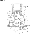
- FIG. 1 is an explanatory view schematically showing an internal combustion engine 1 to which the present invention is applied.
- An internal combustion engine 1 includes a multi-link piston crank mechanism (double-link piston crank mechanism) 4 by which a piston 2 and a crank shaft 3 are linked with each other by a plurality of links.
- the multi-link piston crank mechanism 4 in this embodiment is a variable compression ratio mechanism arranged to vary an upper dead center position of the piston 2 reciprocated within a cylinder 5a of a cylinder block 5, and thereby to vary an engine compression ratio.
- the multi-link piston crank mechanism 4 includes a lower link 7 rotatably mounted to a crank pin 6 of a crank shaft 3; an upper link 8 linking the piston 2 and the lower link 7; and a control link 9 including one end rotatably supported by the cylinder block 5, and the other end rotatably connected to the lower link 7.
- the crank shaft 3 includes a plurality of journal portions 10 and the crank pin 6.
- the journal portions 10 are rotatably supported by crank shaft bearing portions (not shown) which are constituted by the cylinder block 5 and a main bearing cap 11.
- the crank pin 6 is eccentric from the journal portions 10 by a predetermined amount.
- the lower link 7 is rotatably mounted on the crank pin 6.
- FIG. 2 is a sectional view at a central (middle) portion of the lower link 7 in the crank shaft axial direction.
- the lower link 7 includes a crank pin bearing portion 12 rotatably mounted on the crank pin 6 of the crank shaft 3; and one end side protruding piece portion 13 and the other end side protruding piece portion 14 which are positioned on the both sides of the crank pin bearing portion 12.
- the other end side of the upper link 8 is rotatably connected to the one end side protruding piece portion 13.
- the other end side of the control link 9 is rotatably connected to the other end side protruding piece portion 14.
- An input load F1 caused due to the combustion load is acted to the one end side of the lower link 7 from the crank pin 6, as shown by an arrow in FIG. 2 .
- the one end side of the lower link 7 is a side on which the one end side protruding piece portion 13 of the lower link 7 is formed.
- the other end side of the lower link 7 is a side on which the other end side protruding piece portion 14 of the lower link 7 is formed.
- the crank pin bearing portion 12 is a through hole having a circular section.
- the lower link 7 can be divided into two members at a dividing surface at which the crank pin bearing portion 12 is divided into two portions, for assembling the lower link 7 to the crank pin 6.
- the lower link 7 is integrated by two bolts 15 and 15.
- the one end side protruding piece portion 13 has a bifurcated shape which sandwiches the other end side of the upper link 8.
- This one end side protruding piece portion 13 includes a pair of one end side protruding pieces 16 confronting each other.
- Each of the one end protruding pieces 16 includes a lower link one end side pin hole 18 in which a substantially cylindrical first link pin 17 is fixed by the press fit.
- the other end side protruding piece portion 14 has a bifurcated shape which sandwiches the other end side of the control link 9.
- the other end side protruding piece portion 14 includes a pair of the other end side protruding pieces 19 confronting each other.
- Each of the other end side protruding piece portions 19 includes a lower link other end side pin hole 21 in which a substantially cylindrical second link pin 20 is fixed by the press fit.
- the upper link 8 includes an upper link first end portion 23 rotatably mounted to the piston 2 by a piston pin 22; an upper link second end portion 24 rotatably connected to the one end side protruding piece portion 13 of the lower link 7 by the first link pin 17; and an upper link rod portion 25 connecting the upper link first end portion 23 and the upper link second end portion 24.
- the upper link first end portion 23 includes an upper link one end side pin hole (not shown) which is formed at a central portion of the upper link first end portion 23 to penetrate through the upper link first end portion 23, and into which the piston pin 22 is rotatably inserted.
- the upper link second end portion 24 includes an upper link other end side pin hole 26 that is a first through hole which is formed at a central portion of the upper link second end portion 24 to penetrate through the upper link second end portion 24, and into which the first link pin 17 is rotatably inserted.
- the control link 9 is arranged to restrict a movement of the lower link 7.
- the control link 9 includes a control link first end portion 31 rotatably connected to an eccentric shaft portion 42 of a control shaft 41; a control link second end portion 32 rotatably connected to the other end side protruding piece portion 14 of the lower link 7 by the second link pin 20; and a control link rod portion 33 connecting the control link one first portion 31 and the control link second end portion 32.
- the control link first end portion 31 includes a control link one end side pin hole 34 formed at a central portion of the control link first end portion 31 to penetrate through the control link first end portion 31, and into which the eccentric shaft portion 42 is rotatably inserted.
- the control link second end portion 32 includes a control link other end side pin hole 35 that is a second through hole which is formed at a central portion of the control link second end portion 32 to penetrate through the control link second end portion 32, and into which the second link pin 20 is rotatably inserted.
- the control shaft 41 is disposed on a lower side of the crank shaft 3 in parallel with the crank shaft 3.
- the control shaft 41 is rotatably supported on the control shaft bearing portion (not shown) constituted by the main bearing cap 11 and a control shaft bearing cap 43. That is, the control shaft 41 is rotatably supported by the cylinder block 5 which is a part of the engine main body.
- the control shaft 41 is driven and rotated by an actuator (not shown), so that a rotation positon of the control shaft 41 is controlled.
- the actuator may be, for example, an electric motor, or a hydraulically driven actuator.
- the multi-link piston crank mechanism 4 is constituted so that a center C1 of the first link pin 17, a center C2 of the crank pin 6, and a center C3 of the second link pin 20 are aligned in the same line when viewed from the crank shaft axial direction.
- a crank pin oil passage 51 is formed in the crank pin 6.
- the crank pin oil passage 51 passes through the center of the crank pin when viewed from the crank shaft axial direction.
- the crank pin oil passage 51 extends radially within the crank pin 6 in the linear shape.
- both ends of the crank pin oil passage 51 are opened, respectively, on an outer circumference surface of the crank pin 6.
- a lubricant pressurized by an oil pump (not shown) is supplied to this crank pin oil passage 51 through an axial oil passage 52 extending in the crank shaft axial direction.
- the one end side protruding piece portion 13 having the bifurcated shape, and the other end side protruding piece portion 14 having the bifurcated shape are integrally provided on the outer circumference side of the crank pin bearing portion 12. That is, as shown in FIG. 3 , the one end side protruding pieces 16 of the one end side protruding piece portion 13, or the other end side protruding pieces 19 of the other end side protruding piece portion 14 are connected to an outer circumference side of both end portions 12b of the crank pin bearing portion 12 along the crank shaft axial direction.
- a symbol 55 in FIG. 3 is a lubricant oil to lubricate a portion between the crank pin bearing portion 12 and the crank pin 6.
- a lower link 81 of a comparative example in which bifurcated one end side protruding piece portion 83 and bifurcated other end side protruding piece portion 84 are integrally provided on the outer circumference side of a crank pin bearing portion 82 like the lower link 7 in this embodiment, the rigidities of both side portions 82b of the crank pin bearing portion 82 in the crank shaft axial direction is relatively higher than that of a central portion 82a of the crank pin bearing portion 82 in the crank shaft axial direction, as shown in FIG. 4 .
- a symbol 85 in FIG. 4 is a lubricant oil to lubricate a portion between the crank pin bearing portion 82 and the crank pin 6.
- a shape variation amount (deformation amount) of an inner circumference surface of the central portion 82a of the crank pin bearing portion 82 in the crank shaft axial direction, which has the relatively lower rigidity becomes larger than those of inner circumference surfaces of the both end portions 82b of the crank pin bearing portion 82 in the crank shaft axial direction, which has the relatively higher rigidity, at the lubrication of the elastic fluid.
- the lower link 7 is formed so that a thickness (crank pin radial direction thickness) of the central portion 12a of the crank pin bearing portion 12 in the crank shaft axial direction along the crank pin radial direction becomes relatively larger on the one end side of the lower link 7, as shown in FIG. 2 and FIG. 3 . That is, in the thickness of the central portion 12a of the crank pin bearing portion 12 in the crank shaft axial direction along the crank pin radial direction, a portion which is located on the one end side of the lower link 7, and to which the input load F1 due to the combustion load is acted is larger than the portion which is located on the other end side of the lower link 7.
- the thicknesses of the central portion 12a of the crank pin bearing portion 12 in the crank shaft axial direction along the crank pin radial direction are constant, respectively, on the one end side and the other end side of the lower link 7, along the circumferential direction of the crank pin bearing portion.
- the crank pin bearing portion 12 includes an oil hole 61 which is formed in the central portion 12a in the crank shaft axial direction, at the portion that is located on the one end side of the lower link 7, and that has a relatively larger thickness along the crank pin radial direction, and which penetrates through the central portion 12a.
- the oil hole 61 is arranged to supply the lubricant oil from the crank pin side to the upper link second end portion 24.
- the oil hole 61 is formed to be out of the input position of the input load F1 which is acted to the lower link 7 due to the combustion load, and to be out of the positon on the line of the action of the input load F1.
- the oil hole 61 is formed on the linear line passing through the center C1 of the first link pin 17, the center C2 of the crank pin 6, and the center C3 of the second link pin 20 when viewed from the crank shaft axial direction.
- the oil hole 61 is formed at the positon which is on the one side of the lower link 7, and which has the relatively larger thickness along the crank pin radial direction. With this, it is possible to suppress the reduction of the strength of the crank pin bearing portion 12, and to supply the lubricant oil from the crank pin side to the upper link second end portion 24. It is possible to improve the seizure resistance and the abrasion resistance of the lower link one end side pin hole 18 of the upper link second end portion 24 which is the bearing portion of the first link pin 17.
- the oil hole 61 is formed to be out of (off) the input position of the input load F1 which is acted to the lower link 7 due to the combustion load, and to be out of the positon on the line of the action of the input load F1. Accordingly, it is possible to decrease the stress (the tension) generated in the oil hole 61, and to improve the fatigue strength of the portion around the oil hole 61. Moreover, it is possible to suppress the fatigue of the sliding surface of the portion around the upstream opening of the oil hole 61 opened on the inner circumference surface of the crank pin bearing portion 12, in accordance with the improvement of the fatigue strength of the portion around the oil hole 61. It is possible to improve the seizure resistance and the abrasion resistance of the crank pin bearing portion 12.
- the oil hole 61 is formed on the linear line passing through the center C1 of the first link pin 17, the center C2 of the crank pin 6, and the center C3 of the second link pin 20 when viewed from the crank shaft axial direction. Accordingly, it is possible to effectively supply the lubricant oil to the sliding surface of the upper link second end portion 24.
- the forming position of the oil hole 61 needs not be necessarily formed to be out of the position of the input load F1 which is acted to the lower link 7 due to the combustion load, and to be out of the positon on the line of the action of the input load F1 as long as the forming position corresponds to the portion which is located on the one end side of the lower link 7, which has the relatively larger thickness along the crank pin radial direction, in the central portion 12a of the crank pin bearing portion 12 in the crank shaft axial direction. Furthermore, the forming position of the oil hole 61 needs not be positioned on the linear line passing through the center C1 of the first link pin 17, the center C2 of the crank pin 6, and the center C3 of the second link pin 20 when viewed from the crank shaft axial direction.
- the oil hole 61 may be formed to be out of the input positon of the input load F1 which is acted to the lower link 7 due to the combustion load, and to be out of the line of the action of the input load F1, at the portion which is located on the one end side of the lower link 7, and which has the relatively larger thickness along the crank pin radial direction, in the central portion 12a of the crank pin bearing portion 12 in the crank shaft axial direction.
- the thickness of the control link second end portion 32 along the control link other end side pin hole radial direction (hereinafter, referred to as a second through hole radial direction) is formed to be larger than the thickness of the upper link second end portion 24 along the upper link other end side pin hole radial direction (hereinafter, referred to as a first through hole radial direction).
- the input load F2 in the compression direction due to the combustion load, and the input load F3 which is in the pulling direction due to the inertia load smaller than the combustion load are acted from the first link pin 17 to the upper link second end portion 24. Accordingly, the input load F2 inputted to the upper link second end portion 24 due to the combustion load is supported by the upper link second end portion 24 and the upper link rod portion 25. Besides, the input load F2 is greater than the input load F3.
- the input load F4 in the pulling direction due to the combustion load due to the combustion load, and the input load F5 in the compression direction due to the inertial load smaller than the combustion load are acted from the second link pin 20 to the control link second end portion 32. Accordingly, the input load F4 inputted to the control link second end portion 32 due to the combustion load is supported by the control link second end portion 32. Besides, the input load F4 is greater than the input load F5.
- the upper link second end portion 24 can support the large input load F2 due to the combustion load, with the upper link rod portion 25. Accordingly, even when the thickness of the upper link second end portion 24 along the first through hole radial direction is formed to be smaller than the thickness of the control link second end portion 32 along the second through hole radial direction, it is possible to ensure the necessary rigidity.
- the thickness of the central portion 12a of the crank pin bearing portion 12 in the crank shaft axial direction along the crank pin radial direction is not be relatively larger on the other end side of the lower link 7. Accordingly, it is not necessary to decrease the thickness of the control link second end portion 32 along the second through hole radial direction. It is possible to ensure the rigidity of the control link second end portion 32 while avoiding the interference with the lower link 7.
- the thicknesses (second through hole radial direction thicknesses) of the both end portions of the control link second end portion 32 in the control link other end side pin hole axial direction (hereinafter, referred to as a second through hole axial direction) along the second through hole radial direction is formed to be smaller than the thickness (the second through hole radial direction thickness) of the central portion in the second through hole axial direction along the second through hole radial direction, on the side on which the input load F4 is acted due to the combustion load.
- the both end portions of the control link second end portion 32 in the second through hole axial direction are formed so that the thickness along the second through hole radial direction is formed to be smaller toward the both sides in the second through hole axial direction.
- the central portion in the second through hole axial direction has the rigidity higher than those of the both end portions in the second through hole axial direction, on the side on which the input load F4 is acted due to the combustion load.
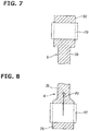
- the shape variation (deformation) of the central portion of the control link second end portion 32 in the second through hole axial direction is relatively suppressed on the side on which the input load F4 is acted due to the combustion load. That is, it is possible to relieve the bearing end portion contacts at which the both end portions in the second through hole axial direction are contacted on the second link pin 20, relative to a case where the thickness along the second through hole radial direction is constant along the second through hole axial direction (cf. FIG. 7 ) on the side on which the input load F4 is acted in the control link second end portion 32. Consequently, it is possible to improve the seizure resistance and the abrasion resistance of the control link other end side pin hole 35.
- the thickness along the second through hole radial direction is relatively larger to increase the strength. Accordingly, it is possible to ensure the necessary strength even when the thicknesses of the both end portions in the second through hole axial direction are formed to be smaller.
- the thicknesses (the first through hole radial direction thicknesses) of the both end portions in the upper link other end side pin hole axial direction (hereinafter, referred to as the first through hole axial direction) along the first through hole radial direction are formed to be smaller than the thickness (the first through hole radial direction thickness) of the central portion in the first through hole axial direction along the first through hole radial direction, on the side on which the input load F4 is acted due to the combustion load.
- the both end portions of the upper link second end portion 24 in the first through hole axial direction are formed so that the thickness along the first through hole radial direction is smaller towards the both sides in the first through hole axial direction.
- the central portion in the first through hole axial direction has the rigidity higher than those of the both end portions in the first through hole axial direction, on the side on which the input load F2 is acted due to the combustion load,.
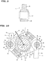
- the shape variation (deformation) of the central portion of the upper link second end portion 24 in the first through hole axial direction is relatively suppressed on the side on which the input load F2 is acted due to the combustion load. That is, it is possible to relieve the bearing end portion contacts at which the both end portions in the first through hole axial direction are contacted on the first link pin 17, relative to a case where the thickness along the first through hole radial direction is constant along the first through hole axial direction (cf. FIG. 9 ) on the side on which the input load F2 is acted in the upper link second end portion 24. Consequently, it is possible to improve the seizure resistance and the abrasion resistance of the upper link other end side pin hole 26.
- the thicknesses of the both end portions in the first through hole axial direction are formed to be smaller in a range in which the necessary strength can be ensured.
- the multi-link piston crank mechanism 4 in this second embodiment has the configuration substantially identical to that of the multi-link piston crank mechanism 4 in the above-described first embodiment.
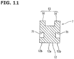
- the thickness (the crank pin radial direction thickness) of the portion which is positioned on the one end side of the lower link 7 along the crank pin radial direction is formed to be relatively larger on the one end side of the lower link 7. This thickness becomes largest at the input position of the input load F1 due to the combustion load. This thickness becomes smaller as it is further apart from the input positon of the input load F1 due to the combustion load along the crank pin bearing portion circumference direction.
- recessed portions 71 are formed on both end surfaces on the one end side of the lower link 7, on the side portion (lateral portion) of the input position of the input load F1 acted to the lower link 7, and on the side portion (lateral portion) of the central portion of the crank pin bearing portion 12 in the crank shaft axial direction.
- the input load F1 due to the combustion load is supported by the portion having the highest rigidity in the portion positioned on the one end side of the lower link 7 of the central portion of the crank pin bearing portion 12 in the crank shaft axial direction.
- the crank pin bearing portion 12 can effectively suppress the shape variation (deformation) of the central portion 12a of the crank pin bearing portion 12 in the crank shaft axial direction, at the input position of the input load F1 on the one end side of the lower link 7. That is, the crank pin bearing portion 12 can effectively relieve the bearing end portion contacts by which the both end portions 12b of the crank pin bearing portion 12 in the crank shaft axial direction are contacted on the crank pin 6.
- the recessed portions 71 are formed on the both end surfaces on the one end side of the lower link 7.
- crank pin bearing portion 12 the rigidity variation in the crank shaft axial direction becomes small on the one end side of the lower link 7. It is possible to further relieve the bearing end portion contacts in which the both end portions 12b in the crank shaft axial direction are contacted on the crank pin 6. Consequently, it is possible to further improve the seizure resistance and the abrasion resistance of the crank pin bearing portion 12.
- the multi-link piston crank mechanism 4 is a variable compression ratio mechanism.
- the present invention is applicable to the multi-link piston crank mechanism which is not the variable compression ratio mechanism.
- the multi-link piston crank mechanism has the configuration substantially identical to that of the multi-link piston crank mechanism 4 in the above-described embodiments.
- this multi-link piston crank mechanism has a configuration in which the control shaft 41 does not include the eccentric shaft portion 42, and the one end of the control link 9 is rotatably connected to the control shaft 41, in the multi-link piston crank mechanism 4 according to the above-described embodiments.
Landscapes
- Engineering & Computer Science (AREA)
- General Engineering & Computer Science (AREA)
- Mechanical Engineering (AREA)
- Chemical & Material Sciences (AREA)
- Combustion & Propulsion (AREA)
- Ocean & Marine Engineering (AREA)
- Shafts, Cranks, Connecting Bars, And Related Bearings (AREA)
- Transmission Devices (AREA)
- Output Control And Ontrol Of Special Type Engine (AREA)
Claims (8)
- Mécanisme à manivelle et à piston à biellettes multiples (4) pour un moteur à combustion interne (1), le mécanisme à manivelle et à piston à biellettes multiples (4) comprenant :une biellette inférieure (7) comprenant une partie porteuse d'axe de manivelle (12) qui est montée de manière rotative sur un axe de manivelle (6) d'un vilebrequin (3) ;une biellette supérieure (8) comprenant une partie de première extrémité (23) reliée à un axe de piston (22) d'un piston (2), et une partie de seconde extrémité (24) reliée à un côté de première extrémité de la biellette inférieure (7) par un premier axe de biellette (17) inséré dans un premier trou traversant (26) de la partie de seconde extrémité (24) de la biellette supérieure (8) ; etune biellette de commande (9) comprenant une partie de première extrémité (31) supportée par un bloc-cylindres (5), et une partie de seconde extrémité (32) reliée au côté de seconde extrémité de la biellette inférieure (7) par un second axe de biellette (20) inséré dans un second trou traversant (35) de la partie de seconde extrémité (32) de la biellette de commande (9) ;la biellette inférieure (7) comprenant le côté de la première extrémité auquel est appliquée une charge d'entrée (F1) du fait d'une charge de combustion, la biellette inférieure (7) comprenant une partie de pièce (13) en saillie du côté de la première extrémité bifurquée et une partie de pièce (14) en saillie du côté de la seconde extrémité bifurquée qui sont positionnées des deux côtés de la partie porteuse d'axe de manivelle (12) vu dans une direction axiale du vilebrequin (3), la partie (13) de pièce en saillie du côté de la première extrémité bifurquée prenant en sandwich la seconde extrémité de la biellette supérieure (8), et la partie de pièce (14) en saillie du côté de la seconde extrémité bifurquée prenant en sandwich la seconde extrémité de la biellette de commande (9), la partie porteuse d'axe de manivelle (12) comprenant une partie centrale (12a) dans la direction axiale du vilebrequin (3), la partie centrale (12a) ayant une épaisseur suivant une direction radiale de l'axe de manivelle (6), l'épaisseur de la partie centrale (12a) au niveau d'une partie placée du côté de la première extrémité de la biellette inférieure (7) étant supérieure à une épaisseur d'une partie placée du côté de la seconde extrémité de la biellette inférieure (7), etune épaisseur de la partie de seconde extrémité de la biellette de commande (9) suivant une direction radiale du second trou traversant (35) étant supérieure à une épaisseur de la partie de seconde extrémité de la biellette supérieure suivant une direction radiale du premier trou traversant (26),dans lequel :
la partie de pièce en saillie (13) du côté de la première extrémité bifurquée de la biellette inférieure (7) comprend une paire de parois (16) qui sont maintenues écartées l'une de l'autre pour prendre en sandwich la partie de seconde extrémité (24) de la biellette supérieure (8) et chacune comprenant un premier trou traversant (18) pour insérer le premier axe de biellette (17), et la partie de pièce en saillie (14) du côté de la seconde extrémité bifurquée de la biellette inférieure (7) comprend une paire de parois (19) qui sont maintenues écartées l'une de l'autre pour prendre en sandwich la partie de seconde extrémité (32) de la biellette de commande (9) et chacune comprenant un second trou traversant (21) pour insérer le second axe de biellette (20), et une pluralité de boulons (15) maintenant les deux parties de la biellette inférieure (7) ensemble sont situés entre les deux parois (16). - Mécanisme à manivelle et à piston à biellettes multiples (4) selon la revendication 1, dans lequel, dans la partie de seconde extrémité (32) de la biellette de commande, les épaisseurs des parties de première et de seconde extrémités dans une direction axiale du second trou traversant (35) suivant la direction radiale du second trou traversant (35) sont inférieures à une épaisseur de la partie centrale (12a) dans la direction axiale du second trou traversant (35) suivant la direction radiale du second trou traversant (35), sur un côté sur lequel la charge d'entrée (F1) est appliquée du fait de la charge de combustion.
- Mécanisme à manivelle et à piston à biellettes multiples (4) selon la revendication 1, dans lequel, dans la partie de seconde extrémité de la biellette supérieure (24), les épaisseurs des parties de première et de seconde extrémité dans une direction axiale du premier trou traversant (26) suivant la direction radiale du premier trou traversant (26) sont inférieures à une épaisseur de la partie centrale (12a) dans la direction axiale du premier trou traversant (26) suivant la direction radiale du premier trou traversant (26), sur un côté sur lequel la force d'entrée (F1) est appliquée du fait de la charge de combustion.
- Mécanisme à manivelle et à piston à biellettes multiples (4) selon l'une des revendications 1 à 3, dans lequel la partie porteuse d'axe de manivelle (12) comprend un trou d'huile (61) qui est formé au niveau d'une partie qui se trouve du côté de la première extrémité de la biellette inférieure (7), dans lequel l'épaisseur suivant la direction radiale de l'axe de manivelle est relativement plus grande, dans la partie centrale (12a) de la partie porteuse d'axe de manivelle (12) dans la direction axiale du vilebrequin et qui est adaptée pour fournir une huile lubrifiante depuis le côté de l'axe de manivelle jusqu'à la partie (24) de seconde extrémité de la biellette supérieure.
- Mécanisme à manivelle et à piston à biellettes multiples (4) selon la revendication 4, dans lequel le trou d'huile (61) est formé dans une position hors d'une position d'entrée de la charge d'entrée (F1) du fait de la charge de combustion appliquée sur la biellette inférieure (7).
- Mécanisme à manivelle et à piston à biellettes multiples (4) selon la revendication 4 ou la revendication 5, dans lequel un centre (C1) du premier axe de biellette (17), un centre (C2) de l'axe de manivelle (6) et un centre (C3) du second axe de biellette (20) sont alignés sur la même ligne linéaire vu dans la direction axiale du vilebrequin (3) ; et le trou d'huile (61) est formé sur une ligne linéaire passant par le centre (C1) du premier axe de biellette (17), le centre (C2) de l'axe de manivelle (6), et le centre (C3) du second axe de biellette (20) vu de la direction axiale du vilebrequin (3).
- Mécanisme à manivelle et à piston biellettes multiples (4) selon l'une des revendications 1 à 6, dans lequel, dans une partie qui est située du côté de la première extrémité de la biellette inférieure (7) dans la partie centrale (12a) de la partie porteuse d'axe de manivelle (12) dans la direction axiale du vilebrequin (3), une épaisseur suivant la direction radiale de l'axe de manivelle (6) devient la plus grande au niveau de la position de la charge d'entrée (F1) du fait de à la charge de combustion ; et l'épaisseur suivant la direction radiale de l'axe de manivelle (6) devient plus petite au fur et à mesure qu'elle s'écarte de la position d'entrée de la charge d'entrée (F1) du fait de la charge de combustion suivant une direction périphérique de la partie porteuse d'axe de manivelle (12).
- Mécanisme à manivelle et à piston à biellettes multiples (4) selon la revendication 7, dans lequel des parties évidées (71) sont formées sur des surfaces de première et de seconde extrémité du côté de la première extrémité de la biellette inférieure (7), sur des parties latérales de la position d'entrée de la charge d'entrée (F1) du fait de la charge de combustion appliquée sur la biellette inférieure (7), sur des parties latérales de la partie centrale (12a) de la partie porteuse d'axe de manivelle (12) dans la direction axiale du vilebrequin (3).
Applications Claiming Priority (1)
| Application Number | Priority Date | Filing Date | Title |
|---|---|---|---|
| PCT/JP2015/050873 WO2016113872A1 (fr) | 2015-01-15 | 2015-01-15 | Mécanisme à piston et manivelle à double biellette pour moteur à combustion interne |
Publications (3)
| Publication Number | Publication Date |
|---|---|
| EP3246543A1 EP3246543A1 (fr) | 2017-11-22 |
| EP3246543A4 EP3246543A4 (fr) | 2017-12-27 |
| EP3246543B1 true EP3246543B1 (fr) | 2020-05-20 |
Family
ID=56405434
Family Applications (1)
| Application Number | Title | Priority Date | Filing Date |
|---|---|---|---|
| EP15877824.1A Active EP3246543B1 (fr) | 2015-01-15 | 2015-01-15 | Mécanisme à piston et manivelle à double biellette pour moteur à combustion interne |
Country Status (9)
| Country | Link |
|---|---|
| US (1) | US10087833B2 (fr) |
| EP (1) | EP3246543B1 (fr) |
| JP (1) | JP6229803B2 (fr) |
| KR (1) | KR101799744B1 (fr) |
| CN (1) | CN107110019B (fr) |
| CA (1) | CA2973535C (fr) |
| MX (1) | MX364194B (fr) |
| RU (1) | RU2652737C1 (fr) |
| WO (1) | WO2016113872A1 (fr) |
Family Cites Families (13)
| Publication number | Priority date | Publication date | Assignee | Title |
|---|---|---|---|---|
| RU2166653C2 (ru) * | 1997-12-24 | 2001-05-10 | Акционерное общество открытого типа - Холдинговая компания "Барнаултрансмаш" | Двигатель внутреннего сгорания |
| JP2004124776A (ja) * | 2002-10-01 | 2004-04-22 | Nissan Motor Co Ltd | 内燃機関の可変圧縮比機構及びリンク部品 |
| JP4057976B2 (ja) * | 2003-08-05 | 2008-03-05 | 本田技研工業株式会社 | 圧縮比可変エンジン |
| JP4779635B2 (ja) * | 2005-12-20 | 2011-09-28 | 日産自動車株式会社 | 内燃機関のピストンクランク機構におけるロアリンク |
| JP4922122B2 (ja) * | 2007-10-11 | 2012-04-25 | 本田技研工業株式会社 | ストローク可変エンジン |
| JP4922121B2 (ja) * | 2007-10-11 | 2012-04-25 | 本田技研工業株式会社 | ストローク可変エンジン |
| JP4941231B2 (ja) | 2007-10-26 | 2012-05-30 | 日産自動車株式会社 | マルチリンクエンジンのリンクジオメトリ |
| JP2009108708A (ja) * | 2007-10-26 | 2009-05-21 | Nissan Motor Co Ltd | マルチリンクエンジンのリンクジオメトリ |
| US8100097B2 (en) * | 2007-10-26 | 2012-01-24 | Nissan Motor Co., Ltd. | Multi-link engine |
| JP4992770B2 (ja) | 2008-03-11 | 2012-08-08 | 日産自動車株式会社 | 内燃機関のピストンクランク機構におけるロアリンク |
| JP5146250B2 (ja) * | 2008-10-20 | 2013-02-20 | 日産自動車株式会社 | 複リンク式エンジンの振動低減構造 |
| WO2011007622A1 (fr) * | 2009-07-17 | 2011-01-20 | 日産自動車株式会社 | Vilebrequin de moteur à combustion interne comprenant un mécanisme piston-vilebrequin du type à liaisons multiples, et mécanisme piston-vilebrequin du type à liaisons multiples pour moteur à combustion interne |
| DE102011104531A1 (de) * | 2011-06-18 | 2012-12-20 | Audi Ag | Brennkraftmaschine |
-
2015
- 2015-01-15 CA CA2973535A patent/CA2973535C/fr active Active
- 2015-01-15 WO PCT/JP2015/050873 patent/WO2016113872A1/fr not_active Ceased
- 2015-01-15 KR KR1020177022259A patent/KR101799744B1/ko active Active
- 2015-01-15 EP EP15877824.1A patent/EP3246543B1/fr active Active
- 2015-01-15 RU RU2017128854A patent/RU2652737C1/ru active
- 2015-01-15 MX MX2017008630A patent/MX364194B/es active IP Right Grant
- 2015-01-15 CN CN201580073456.3A patent/CN107110019B/zh active Active
- 2015-01-15 JP JP2016569169A patent/JP6229803B2/ja active Active
- 2015-01-15 US US15/543,662 patent/US10087833B2/en active Active
Non-Patent Citations (1)
| Title |
|---|
| None * |
Also Published As
| Publication number | Publication date |
|---|---|
| MX2017008630A (es) | 2017-10-20 |
| US10087833B2 (en) | 2018-10-02 |
| CN107110019A (zh) | 2017-08-29 |
| CN107110019B (zh) | 2018-06-29 |
| WO2016113872A1 (fr) | 2016-07-21 |
| CA2973535A1 (fr) | 2016-07-21 |
| MX364194B (es) | 2019-04-16 |
| JPWO2016113872A1 (ja) | 2017-08-31 |
| RU2652737C1 (ru) | 2018-04-28 |
| EP3246543A1 (fr) | 2017-11-22 |
| CA2973535C (fr) | 2018-01-23 |
| KR101799744B1 (ko) | 2017-11-20 |
| JP6229803B2 (ja) | 2017-11-15 |
| KR20170096211A (ko) | 2017-08-23 |
| US20180023467A1 (en) | 2018-01-25 |
| EP3246543A4 (fr) | 2017-12-27 |
Similar Documents
| Publication | Publication Date | Title |
|---|---|---|
| JP5971422B2 (ja) | 内燃機関の複リンク式ピストンクランク機構 | |
| CN102482995A (zh) | 设置有多连杆型活塞-曲柄机构的内燃机的曲轴和内燃机的多连杆型活塞-曲柄机构 | |
| EP3181925B1 (fr) | Structure de palier | |
| US8826882B2 (en) | Lubricating structure of multi-link piston-crank mechanism for internal combustion engine | |
| JP2008208783A (ja) | リンク機構の軸受構造 | |
| EP3190281B1 (fr) | Moteur à combustion interne à taux de compression variable | |
| CA2973535C (fr) | Mecanisme a piston et manivelle a double biellette pour moteur a combustion interne | |
| EP3040535B1 (fr) | Mécanisme à bielle et piston à liaison multiple pour un moteur à combustion interne | |
| KR101554379B1 (ko) | 피스톤 베어링 장치 | |
| WO2015025684A1 (fr) | Moteur à combustion interne | |
| JP6355903B2 (ja) | ロアリンクのクランクピン連結構造 | |
| JP5205991B2 (ja) | リンク機構の軸受構造 | |
| JP5321724B2 (ja) | リンク機構の軸受構造 | |
| EP3805537B1 (fr) | Mécanisme de bielle de piston à éléments de liaison multiples pour moteur à combustion interne | |
| JP5321148B2 (ja) | 複リンク式可変圧縮比内燃機関 | |
| JP4670342B2 (ja) | 内燃機関のピストンクランク機構におけるロアリンク | |
| JP2019143751A (ja) | 可変圧縮比内燃機関 | |
| JP2016033377A (ja) | リンク機構 |
Legal Events
| Date | Code | Title | Description |
|---|---|---|---|
| STAA | Information on the status of an ep patent application or granted ep patent |
Free format text: STATUS: THE INTERNATIONAL PUBLICATION HAS BEEN MADE |
|
| PUAI | Public reference made under article 153(3) epc to a published international application that has entered the european phase |
Free format text: ORIGINAL CODE: 0009012 |
|
| STAA | Information on the status of an ep patent application or granted ep patent |
Free format text: STATUS: REQUEST FOR EXAMINATION WAS MADE |
|
| 17P | Request for examination filed |
Effective date: 20170810 |
|
| AK | Designated contracting states |
Kind code of ref document: A1 Designated state(s): AL AT BE BG CH CY CZ DE DK EE ES FI FR GB GR HR HU IE IS IT LI LT LU LV MC MK MT NL NO PL PT RO RS SE SI SK SM TR |
|
| AX | Request for extension of the european patent |
Extension state: BA ME |
|
| A4 | Supplementary search report drawn up and despatched |
Effective date: 20171124 |
|
| RIC1 | Information provided on ipc code assigned before grant |
Ipc: F02B 75/32 20060101ALI20171120BHEP Ipc: F02B 75/04 20060101AFI20171120BHEP |
|
| DAX | Request for extension of the european patent (deleted) | ||
| STAA | Information on the status of an ep patent application or granted ep patent |
Free format text: STATUS: EXAMINATION IS IN PROGRESS |
|
| 17Q | First examination report despatched |
Effective date: 20181108 |
|
| GRAP | Despatch of communication of intention to grant a patent |
Free format text: ORIGINAL CODE: EPIDOSNIGR1 |
|
| STAA | Information on the status of an ep patent application or granted ep patent |
Free format text: STATUS: GRANT OF PATENT IS INTENDED |
|
| INTG | Intention to grant announced |
Effective date: 20191024 |
|
| GRAJ | Information related to disapproval of communication of intention to grant by the applicant or resumption of examination proceedings by the epo deleted |
Free format text: ORIGINAL CODE: EPIDOSDIGR1 |
|
| STAA | Information on the status of an ep patent application or granted ep patent |
Free format text: STATUS: EXAMINATION IS IN PROGRESS |
|
| STAA | Information on the status of an ep patent application or granted ep patent |
Free format text: STATUS: GRANT OF PATENT IS INTENDED |
|
| INTC | Intention to grant announced (deleted) | ||
| GRAS | Grant fee paid |
Free format text: ORIGINAL CODE: EPIDOSNIGR3 |
|
| GRAA | (expected) grant |
Free format text: ORIGINAL CODE: 0009210 |
|
| STAA | Information on the status of an ep patent application or granted ep patent |
Free format text: STATUS: THE PATENT HAS BEEN GRANTED |
|
| AK | Designated contracting states |
Kind code of ref document: B1 Designated state(s): AL AT BE BG CH CY CZ DE DK EE ES FI FR GB GR HR HU IE IS IT LI LT LU LV MC MK MT NL NO PL PT RO RS SE SI SK SM TR |
|
| REG | Reference to a national code |
Ref country code: GB Ref legal event code: FG4D |
|
| REG | Reference to a national code |
Ref country code: CH Ref legal event code: EP |
|
| REG | Reference to a national code |
Ref country code: DE Ref legal event code: R096 Ref document number: 602015053176 Country of ref document: DE |
|
| REG | Reference to a national code |
Ref country code: AT Ref legal event code: REF Ref document number: 1272742 Country of ref document: AT Kind code of ref document: T Effective date: 20200615 |
|
| REG | Reference to a national code |
Ref country code: LT Ref legal event code: MG4D |
|
| REG | Reference to a national code |
Ref country code: NL Ref legal event code: MP Effective date: 20200520 |
|
| PG25 | Lapsed in a contracting state [announced via postgrant information from national office to epo] |
Ref country code: LT Free format text: LAPSE BECAUSE OF FAILURE TO SUBMIT A TRANSLATION OF THE DESCRIPTION OR TO PAY THE FEE WITHIN THE PRESCRIBED TIME-LIMIT Effective date: 20200520 Ref country code: IS Free format text: LAPSE BECAUSE OF FAILURE TO SUBMIT A TRANSLATION OF THE DESCRIPTION OR TO PAY THE FEE WITHIN THE PRESCRIBED TIME-LIMIT Effective date: 20200920 Ref country code: PT Free format text: LAPSE BECAUSE OF FAILURE TO SUBMIT A TRANSLATION OF THE DESCRIPTION OR TO PAY THE FEE WITHIN THE PRESCRIBED TIME-LIMIT Effective date: 20200921 Ref country code: FI Free format text: LAPSE BECAUSE OF FAILURE TO SUBMIT A TRANSLATION OF THE DESCRIPTION OR TO PAY THE FEE WITHIN THE PRESCRIBED TIME-LIMIT Effective date: 20200520 Ref country code: GR Free format text: LAPSE BECAUSE OF FAILURE TO SUBMIT A TRANSLATION OF THE DESCRIPTION OR TO PAY THE FEE WITHIN THE PRESCRIBED TIME-LIMIT Effective date: 20200821 Ref country code: NO Free format text: LAPSE BECAUSE OF FAILURE TO SUBMIT A TRANSLATION OF THE DESCRIPTION OR TO PAY THE FEE WITHIN THE PRESCRIBED TIME-LIMIT Effective date: 20200820 Ref country code: SE Free format text: LAPSE BECAUSE OF FAILURE TO SUBMIT A TRANSLATION OF THE DESCRIPTION OR TO PAY THE FEE WITHIN THE PRESCRIBED TIME-LIMIT Effective date: 20200520 |
|
| PG25 | Lapsed in a contracting state [announced via postgrant information from national office to epo] |
Ref country code: BG Free format text: LAPSE BECAUSE OF FAILURE TO SUBMIT A TRANSLATION OF THE DESCRIPTION OR TO PAY THE FEE WITHIN THE PRESCRIBED TIME-LIMIT Effective date: 20200820 Ref country code: RS Free format text: LAPSE BECAUSE OF FAILURE TO SUBMIT A TRANSLATION OF THE DESCRIPTION OR TO PAY THE FEE WITHIN THE PRESCRIBED TIME-LIMIT Effective date: 20200520 Ref country code: HR Free format text: LAPSE BECAUSE OF FAILURE TO SUBMIT A TRANSLATION OF THE DESCRIPTION OR TO PAY THE FEE WITHIN THE PRESCRIBED TIME-LIMIT Effective date: 20200520 Ref country code: LV Free format text: LAPSE BECAUSE OF FAILURE TO SUBMIT A TRANSLATION OF THE DESCRIPTION OR TO PAY THE FEE WITHIN THE PRESCRIBED TIME-LIMIT Effective date: 20200520 |
|
| REG | Reference to a national code |
Ref country code: AT Ref legal event code: MK05 Ref document number: 1272742 Country of ref document: AT Kind code of ref document: T Effective date: 20200520 |
|
| PG25 | Lapsed in a contracting state [announced via postgrant information from national office to epo] |
Ref country code: AL Free format text: LAPSE BECAUSE OF FAILURE TO SUBMIT A TRANSLATION OF THE DESCRIPTION OR TO PAY THE FEE WITHIN THE PRESCRIBED TIME-LIMIT Effective date: 20200520 Ref country code: NL Free format text: LAPSE BECAUSE OF FAILURE TO SUBMIT A TRANSLATION OF THE DESCRIPTION OR TO PAY THE FEE WITHIN THE PRESCRIBED TIME-LIMIT Effective date: 20200520 |
|
| PG25 | Lapsed in a contracting state [announced via postgrant information from national office to epo] |
Ref country code: ES Free format text: LAPSE BECAUSE OF FAILURE TO SUBMIT A TRANSLATION OF THE DESCRIPTION OR TO PAY THE FEE WITHIN THE PRESCRIBED TIME-LIMIT Effective date: 20200520 Ref country code: EE Free format text: LAPSE BECAUSE OF FAILURE TO SUBMIT A TRANSLATION OF THE DESCRIPTION OR TO PAY THE FEE WITHIN THE PRESCRIBED TIME-LIMIT Effective date: 20200520 Ref country code: SM Free format text: LAPSE BECAUSE OF FAILURE TO SUBMIT A TRANSLATION OF THE DESCRIPTION OR TO PAY THE FEE WITHIN THE PRESCRIBED TIME-LIMIT Effective date: 20200520 Ref country code: AT Free format text: LAPSE BECAUSE OF FAILURE TO SUBMIT A TRANSLATION OF THE DESCRIPTION OR TO PAY THE FEE WITHIN THE PRESCRIBED TIME-LIMIT Effective date: 20200520 Ref country code: DK Free format text: LAPSE BECAUSE OF FAILURE TO SUBMIT A TRANSLATION OF THE DESCRIPTION OR TO PAY THE FEE WITHIN THE PRESCRIBED TIME-LIMIT Effective date: 20200520 Ref country code: IT Free format text: LAPSE BECAUSE OF FAILURE TO SUBMIT A TRANSLATION OF THE DESCRIPTION OR TO PAY THE FEE WITHIN THE PRESCRIBED TIME-LIMIT Effective date: 20200520 Ref country code: RO Free format text: LAPSE BECAUSE OF FAILURE TO SUBMIT A TRANSLATION OF THE DESCRIPTION OR TO PAY THE FEE WITHIN THE PRESCRIBED TIME-LIMIT Effective date: 20200520 Ref country code: CZ Free format text: LAPSE BECAUSE OF FAILURE TO SUBMIT A TRANSLATION OF THE DESCRIPTION OR TO PAY THE FEE WITHIN THE PRESCRIBED TIME-LIMIT Effective date: 20200520 |
|
| REG | Reference to a national code |
Ref country code: DE Ref legal event code: R097 Ref document number: 602015053176 Country of ref document: DE |
|
| PG25 | Lapsed in a contracting state [announced via postgrant information from national office to epo] |
Ref country code: PL Free format text: LAPSE BECAUSE OF FAILURE TO SUBMIT A TRANSLATION OF THE DESCRIPTION OR TO PAY THE FEE WITHIN THE PRESCRIBED TIME-LIMIT Effective date: 20200520 Ref country code: SK Free format text: LAPSE BECAUSE OF FAILURE TO SUBMIT A TRANSLATION OF THE DESCRIPTION OR TO PAY THE FEE WITHIN THE PRESCRIBED TIME-LIMIT Effective date: 20200520 |
|
| PLBE | No opposition filed within time limit |
Free format text: ORIGINAL CODE: 0009261 |
|
| STAA | Information on the status of an ep patent application or granted ep patent |
Free format text: STATUS: NO OPPOSITION FILED WITHIN TIME LIMIT |
|
| 26N | No opposition filed |
Effective date: 20210223 |
|
| PG25 | Lapsed in a contracting state [announced via postgrant information from national office to epo] |
Ref country code: SI Free format text: LAPSE BECAUSE OF FAILURE TO SUBMIT A TRANSLATION OF THE DESCRIPTION OR TO PAY THE FEE WITHIN THE PRESCRIBED TIME-LIMIT Effective date: 20200520 |
|
| PG25 | Lapsed in a contracting state [announced via postgrant information from national office to epo] |
Ref country code: MC Free format text: LAPSE BECAUSE OF FAILURE TO SUBMIT A TRANSLATION OF THE DESCRIPTION OR TO PAY THE FEE WITHIN THE PRESCRIBED TIME-LIMIT Effective date: 20200520 |
|
| REG | Reference to a national code |
Ref country code: CH Ref legal event code: PL |
|
| PG25 | Lapsed in a contracting state [announced via postgrant information from national office to epo] |
Ref country code: LU Free format text: LAPSE BECAUSE OF NON-PAYMENT OF DUE FEES Effective date: 20210115 |
|
| REG | Reference to a national code |
Ref country code: BE Ref legal event code: MM Effective date: 20210131 |
|
| PG25 | Lapsed in a contracting state [announced via postgrant information from national office to epo] |
Ref country code: LI Free format text: LAPSE BECAUSE OF NON-PAYMENT OF DUE FEES Effective date: 20210131 Ref country code: CH Free format text: LAPSE BECAUSE OF NON-PAYMENT OF DUE FEES Effective date: 20210131 |
|
| PG25 | Lapsed in a contracting state [announced via postgrant information from national office to epo] |
Ref country code: IE Free format text: LAPSE BECAUSE OF NON-PAYMENT OF DUE FEES Effective date: 20210115 |
|
| PG25 | Lapsed in a contracting state [announced via postgrant information from national office to epo] |
Ref country code: BE Free format text: LAPSE BECAUSE OF NON-PAYMENT OF DUE FEES Effective date: 20210131 |
|
| PG25 | Lapsed in a contracting state [announced via postgrant information from national office to epo] |
Ref country code: HU Free format text: LAPSE BECAUSE OF FAILURE TO SUBMIT A TRANSLATION OF THE DESCRIPTION OR TO PAY THE FEE WITHIN THE PRESCRIBED TIME-LIMIT; INVALID AB INITIO Effective date: 20150115 |
|
| PG25 | Lapsed in a contracting state [announced via postgrant information from national office to epo] |
Ref country code: CY Free format text: LAPSE BECAUSE OF FAILURE TO SUBMIT A TRANSLATION OF THE DESCRIPTION OR TO PAY THE FEE WITHIN THE PRESCRIBED TIME-LIMIT Effective date: 20200520 |
|
| PG25 | Lapsed in a contracting state [announced via postgrant information from national office to epo] |
Ref country code: MK Free format text: LAPSE BECAUSE OF FAILURE TO SUBMIT A TRANSLATION OF THE DESCRIPTION OR TO PAY THE FEE WITHIN THE PRESCRIBED TIME-LIMIT Effective date: 20200520 |
|
| PG25 | Lapsed in a contracting state [announced via postgrant information from national office to epo] |
Ref country code: TR Free format text: LAPSE BECAUSE OF FAILURE TO SUBMIT A TRANSLATION OF THE DESCRIPTION OR TO PAY THE FEE WITHIN THE PRESCRIBED TIME-LIMIT Effective date: 20200520 |
|
| PG25 | Lapsed in a contracting state [announced via postgrant information from national office to epo] |
Ref country code: MT Free format text: LAPSE BECAUSE OF FAILURE TO SUBMIT A TRANSLATION OF THE DESCRIPTION OR TO PAY THE FEE WITHIN THE PRESCRIBED TIME-LIMIT Effective date: 20200520 |
|
| PGFP | Annual fee paid to national office [announced via postgrant information from national office to epo] |
Ref country code: GB Payment date: 20251220 Year of fee payment: 12 |
|
| PGFP | Annual fee paid to national office [announced via postgrant information from national office to epo] |
Ref country code: FR Payment date: 20251217 Year of fee payment: 12 |
|
| PGFP | Annual fee paid to national office [announced via postgrant information from national office to epo] |
Ref country code: DE Payment date: 20251217 Year of fee payment: 12 |