EP3246599A1 - Sélecteur de vitesses de véhicule comprenant un actionneur de câble de décalage - Google Patents
Sélecteur de vitesses de véhicule comprenant un actionneur de câble de décalage Download PDFInfo
- Publication number
- EP3246599A1 EP3246599A1 EP17166932.8A EP17166932A EP3246599A1 EP 3246599 A1 EP3246599 A1 EP 3246599A1 EP 17166932 A EP17166932 A EP 17166932A EP 3246599 A1 EP3246599 A1 EP 3246599A1
- Authority
- EP
- European Patent Office
- Prior art keywords
- pivot
- cable
- shift
- shifter
- shift member
- Prior art date
- Legal status (The legal status is an assumption and is not a legal conclusion. Google has not performed a legal analysis and makes no representation as to the accuracy of the status listed.)
- Withdrawn
Links
Images



Classifications
-
- F—MECHANICAL ENGINEERING; LIGHTING; HEATING; WEAPONS; BLASTING
- F16—ENGINEERING ELEMENTS AND UNITS; GENERAL MEASURES FOR PRODUCING AND MAINTAINING EFFECTIVE FUNCTIONING OF MACHINES OR INSTALLATIONS; THERMAL INSULATION IN GENERAL
- F16H—GEARING
- F16H59/00—Control inputs to control units of change-speed- or reversing-gearings for conveying rotary motion
- F16H59/02—Selector apparatus
- F16H59/08—Range selector apparatus
- F16H59/10—Range selector apparatus comprising levers
-
- F—MECHANICAL ENGINEERING; LIGHTING; HEATING; WEAPONS; BLASTING
- F16—ENGINEERING ELEMENTS AND UNITS; GENERAL MEASURES FOR PRODUCING AND MAINTAINING EFFECTIVE FUNCTIONING OF MACHINES OR INSTALLATIONS; THERMAL INSULATION IN GENERAL
- F16C—SHAFTS; FLEXIBLE SHAFTS; ELEMENTS OR CRANKSHAFT MECHANISMS; ROTARY BODIES OTHER THAN GEARING ELEMENTS; BEARINGS
- F16C1/00—Flexible shafts; Mechanical means for transmitting movement in a flexible sheathing
- F16C1/10—Means for transmitting linear movement in a flexible sheathing, e.g. "Bowden-mechanisms"
- F16C1/12—Arrangements for transmitting movement to or from the flexible member
- F16C1/14—Construction of the end-piece of the flexible member; Attachment thereof to the flexible member
-
- B—PERFORMING OPERATIONS; TRANSPORTING
- B60—VEHICLES IN GENERAL
- B60K—ARRANGEMENT OR MOUNTING OF PROPULSION UNITS OR OF TRANSMISSIONS IN VEHICLES; ARRANGEMENT OR MOUNTING OF PLURAL DIVERSE PRIME-MOVERS IN VEHICLES; AUXILIARY DRIVES FOR VEHICLES; INSTRUMENTATION OR DASHBOARDS FOR VEHICLES; ARRANGEMENTS IN CONNECTION WITH COOLING, AIR INTAKE, GAS EXHAUST OR FUEL SUPPLY OF PROPULSION UNITS IN VEHICLES
- B60K20/00—Arrangement or mounting of change-speed gearing control devices in vehicles
- B60K20/02—Arrangement or mounting of change-speed gearing control devices in vehicles of initiating means
- B60K20/06—Arrangement or mounting of change-speed gearing control devices in vehicles of initiating means mounted on steering column or the like
-
- F—MECHANICAL ENGINEERING; LIGHTING; HEATING; WEAPONS; BLASTING
- F16—ENGINEERING ELEMENTS AND UNITS; GENERAL MEASURES FOR PRODUCING AND MAINTAINING EFFECTIVE FUNCTIONING OF MACHINES OR INSTALLATIONS; THERMAL INSULATION IN GENERAL
- F16H—GEARING
- F16H59/00—Control inputs to control units of change-speed- or reversing-gearings for conveying rotary motion
- F16H59/02—Selector apparatus
- F16H59/0204—Selector apparatus for automatic transmissions with means for range selection and manual shifting, e.g. range selector with tiptronic
-
- F—MECHANICAL ENGINEERING; LIGHTING; HEATING; WEAPONS; BLASTING
- F16—ENGINEERING ELEMENTS AND UNITS; GENERAL MEASURES FOR PRODUCING AND MAINTAINING EFFECTIVE FUNCTIONING OF MACHINES OR INSTALLATIONS; THERMAL INSULATION IN GENERAL
- F16H—GEARING
- F16H59/00—Control inputs to control units of change-speed- or reversing-gearings for conveying rotary motion
- F16H59/02—Selector apparatus
- F16H59/08—Range selector apparatus
-
- F—MECHANICAL ENGINEERING; LIGHTING; HEATING; WEAPONS; BLASTING
- F16—ENGINEERING ELEMENTS AND UNITS; GENERAL MEASURES FOR PRODUCING AND MAINTAINING EFFECTIVE FUNCTIONING OF MACHINES OR INSTALLATIONS; THERMAL INSULATION IN GENERAL
- F16H—GEARING
- F16H61/00—Control functions within control units of change-speed- or reversing-gearings for conveying rotary motion ; Control of exclusively fluid gearing, friction gearing, gearings with endless flexible members or other particular types of gearing
- F16H61/26—Generation or transmission of movements for final actuating mechanisms
- F16H61/36—Generation or transmission of movements for final actuating mechanisms with at least one movement being transmitted by a cable
-
- F—MECHANICAL ENGINEERING; LIGHTING; HEATING; WEAPONS; BLASTING
- F16—ENGINEERING ELEMENTS AND UNITS; GENERAL MEASURES FOR PRODUCING AND MAINTAINING EFFECTIVE FUNCTIONING OF MACHINES OR INSTALLATIONS; THERMAL INSULATION IN GENERAL
- F16H—GEARING
- F16H59/00—Control inputs to control units of change-speed- or reversing-gearings for conveying rotary motion
- F16H59/02—Selector apparatus
- F16H2059/0239—Up- and down-shift or range or mode selection by repeated movement
- F16H2059/0247—Up- and down-shift or range or mode selection by repeated movement with lever or paddle behind steering wheel
-
- F—MECHANICAL ENGINEERING; LIGHTING; HEATING; WEAPONS; BLASTING
- F16—ENGINEERING ELEMENTS AND UNITS; GENERAL MEASURES FOR PRODUCING AND MAINTAINING EFFECTIVE FUNCTIONING OF MACHINES OR INSTALLATIONS; THERMAL INSULATION IN GENERAL
- F16H—GEARING
- F16H59/00—Control inputs to control units of change-speed- or reversing-gearings for conveying rotary motion
- F16H59/02—Selector apparatus
- F16H2059/026—Details or special features of the selector casing or lever support
- F16H2059/0265—Selector lever support with pivot axis offset, e.g. support by four bar linkage to create pivoting centre outside the mechanism
Definitions
- the present disclosure relates to a vehicle transmission shifter with a cable actuator offset relative to an axis of the shifter.
- a gear shift lever in a passenger compartment of the vehicle can be moved by an operator of the vehicle to shift the vehicle transmission between its park gear and other gears, such as reverse, neutral and forward drive gears.
- the shift lever is mechanically coupled to the transmission through a cable that transmits the shift lever movement to a transmission shift mechanism.
- a shifter for a vehicle transmission includes a shift member and a cable actuator.
- the shift member is pivoted at a first pivot for movement between multiple positions corresponding to multiple transmission gears.
- the cable actuator pivoted at a second pivot, driven for movement about the second pivot by movement of the shift member about the first pivot and has a cable connector adapted to be connected to a shift cable that is associated with the vehicle transmission, wherein the first pivot is arranged about a first axis and the second pivot is arranged about a second axis that is not parallel to the first axis.
- This disclosure also relates to a shifter for a vehicle transmission that may include a shift member, a cable actuator and a shift cable.
- the shift member is pivoted at a first pivot for movement between multiple positions corresponding to multiple transmission gears.
- the cable actuator is pivoted at a second pivot, driven for movement about the second pivot by movement of the shift member about the first pivot and has a cable connector.
- the first pivot is arranged about a first axis and the second pivot is arranged about a second axis that is not parallel to the first axis.
- the shift cable has a core received within a conduit and movable relative to the conduit.
- the core is connected to the cable connector and movement of the cable actuator about the second pivot moves the core relative to the conduit.
- the shift cable is adapted to be connected to a transmission shift mechanism so that movement of the core causes a transmission shift when the shifter is installed on the vehicle.
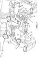
- FIG. 1 illustrates a portion of a vehicle dashboard or instrument panel 10 with the interior trim removed to show components mounted behind the trim.
- a vehicle transmission shifter assembly 12 is mounted to the instrument panel 10 adjacent to a steering assembly 14 including a main shaft 16 an end 18 of which would receive a steering wheel when the vehicle is assembled.
- the shifter assembly 12 could also be mounted to the steering assembly 14 (e.g. column mounted) or at a location spaced from the instrument panel or dashboard (e.g. in a center console between two vehicle seats).
- the shifter assembly 12 includes a shift member or lever 20 that may be moved by a driver to, through a cable 21 associated with the transmission, cause a vehicle transmission to shift among various gears, often including park, neutral, reverse and one or more forward or drive gears.
- the shifter assembly 12 includes a housing 22 or mounting bracket with a base 24 adapted to be fixed to the vehicle such as by suitable fasteners, and one or more wall or supports 26 extending outwardly from the base.
- the shift member 20 is coupled to one or more supports 26 at a first pivot 28 so that the shift member may rotate or pivot about a first axis 30 relative to the housing 22 between multiple positions that correspond to the various transmission gears or positions.
- the pivot 28 may include or be defined by a pin or shaft coupled to a support 26.
- the shift member 20 may have a first end 32 spaced from the housing 22 and adapted to receive or carry a handle 34 that, in use, is manually gripped to facilitate pivoting changing the position of the shift member.
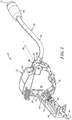
- the shift member 20 may have a second end 36 ( FIG. 3 ), where the second end is on the opposite side of the pivot 28 from the first end 32. That is, the shift member 20 is pivoted between its ends 32, 36.
- the first end is outside of and not received within the housing and the second end 36 is received within the housing 22 and, in assembly of the vehicle, is hidden behind an interior trim piece, such as a dashboard or instrument panel covering.
- the shift member 20 may be formed in one piece, or multiple pieces, as desired.
- the shift member 20 includes an elongated rod 38 coupled to a base 40, where the base is coupled to the pivot 28 and extends beyond the pivot to define the second end 36 of the shift member.
- the base 40 may include or be coupled to other features of the shifter assembly 12.
- the base 40 may include or carry a follower 42 on an opposite side of the pivot axis 30 from the handle.
- the follower 42 is shown at an end of a projection 44 extending away from the pivot 28 so that the follower is moved along an arc as the shift member 20 is pivoted.
- the follower 42 moves along a surface 46 that includes one or more detents 48. Movement of the shift member 20 relative to the housing 22 moves the follower 42 among the detents 48, and when the follower is in a detent, the transmission is in a corresponding one of its gears.
- moving the shift member 20 to move the follower 42 from one detent 48 to the next detent causes the transmission to shift from one gear to the next.
- the interaction of the follower 42 with the detents 48 provides tactile feedback to a driver indicating when a vehicle transmission shift is complete, for example, so that the driver does not stop moving the shift member 20 midway between two positions which might not cause the desired transmission shift.
- the follower 42 when received in a detent 48, may also help hold or retain the position of the shift member 20 until the shift member is acted upon by someone intended to cause a transmission shift.
- the shift member base 40 may include a coupler 50 that, in assembly, is connected to a cable actuator 52.
- the coupler 50 is located at or adjacent to the second end 36 of the base 40, and may be located within the housing, if desired.
- the coupler 50 includes a peg 53 extending outwardly from the base 40, at a desired angle, and is shown as being parallel or generally parallel to the pivot axis 30, although that is just one of many possibilities.
- the peg 53 in the implementation shown, is carried by a link 54 that is coupled to the base 40 at a coupler pivot 56 so that the link 54 may rotate relative to the base 40 about an axis 58 of the coupler pivot.
- the coupler pivot axis 58 ( FIG. 5 ) is parallel to the first pivot axis 30 although that angle may be different in different embodiments.
- the peg 53 is not constrained to move along an arc that is a fixed distance from the first pivot axis 30; the peg 53 may also move relative to the first pivot axis 30 about the coupler pivot axis 58.
- the cable actuator 52 includes a coupler 60 that is adapted to mate with the shift member coupler 50 so that the cable actuator is actively driven by movement of the shift member 20.
- the cable actuator coupler 60 includes a socket 62 or void in which the peg 53 is received. Because the peg 53 moves as the shift member 20 moves, the cable actuator 52 is moved as the shift member moves. Arrangements other than the peg 53 and socket 62 may be used to couple the base 40 and cable actuator 52.
- the cable actuator 52 further includes a cable connector 64 that is adapted to connect to the transmission shift cable 21 so that the shift cable is driven as the cable actuator 52 moves.
- the shift cable 21 may be a bowden-style cable having a tubular conduit 66 surrounding an inner core 68 that may be pushed and pulled for movement relative to the conduit.
- the conduit 66 may be held in place at each of its ends, and the core 68 may be coupled at one end to the cable actuator 52 and at its other end to a shifting mechanism of the transmission.
- the conduit 66 may be coupled to a bracket 70 extending from the housing 22, and the core 68 may be coupled to a connector 72 ( FIG. 2 ) that is coupled to the cable connector 64 of the cable actuator 52.
- movement of the shift member 20 moves the cable actuator 52 which moves the shift cable core 68 relative to the conduit 66 to move the transmission shifting mechanism and cause a transmission shift.
- the cable actuator 52 is coupled to the housing 22 (or an adjacent structure) at a second pivot 74, spaced from the coupler 60 and the first pivot 28, and preferably also spaced from the cable connector 64.
- the cable actuator 52 may include a body 76 that extends between the coupler 60, second pivot 74 and cable connector 64.
- the body may be rigid so that all parts of the body move in unison and without movement relative to each other.
- the body 76 is formed from molded plastic so that all features of the body are defined in one continuous body.
- the continuous body 76 may include overmolded inserts that may be used for strength and to define or reinforce the coupler 60 or the cable connector 64 as desired.
- the body 76 need not be an entirely homogenous piece of plastic but may nevertheless be a single piece rather than multiple pieces connected together by fasteners, welding or some process done after formation of the body.
- the second pivot 74 defines a second axis 78 that is offset from and not parallel to the first axis 30.
- the cable connector 64 may be oriented to drive the shift cable 21 in a direction that is not parallel to the second axis 78. In this way, the direction in which the shift cable 21 is driven may be altered to enable a desired routing of the shift cable within the vehicle. The routing of the shift cable 21 may be constrained by other components, a desired overall size of the shifter assembly, or other factors.
- the shift cable is connected to and driven by the shift lever in a direction perpendicular to an axis about which the shift lever pivots (called the first axis in this disclosure).
- the first axis 30 extends in a cross-car direction, where the cross-car direction is between a driver side and a passenger side of the vehicle, perpendicular to a fore-aft direction which is between the front and rear of the vehicle. Therefore, in a conventional shifter assembly, the shift cable is driven in the fore-aft direction, perpendicular to the cross-car direction.
- the shift cable 21 may be driven in a direction at least 20 degrees offset or inclined (in either direction) relative to the fore-aft direction, and can be driven in the cross-car direction, 90 degrees offset from the fore-aft direction, if desired.
- this enables the shift cable 21 to extend from the shifter assembly 12 generally parallel to the instrument panel which may reduce the fore-aft dimension of the shifter assembly 12 which may reduce the amount that the shifter (i.e. adjacent portion of dashboard trim) extends into a passenger compartment of the vehicle or otherwise meet customer location and dimension criteria.
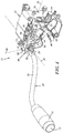
- FIGS. 2-5 drives the shift cable 21 parallel to the first pivot axis 30 and perpendicular to the second pivot axis 78.
- the first and second pivot axes 30, 78 are perpendicular to each other, and the cable connector 64 extends perpendicular to the second pivot axis 78 so that the point of connection between the cable connector 64 and the shift cable 21 sweeps a path that is perpendicular to the second pivot axis 78.
- the second pivot axis 78 could be inclined relative to the first pivot axis 30 at an angle other than 90 degrees to achieve a different drive direction for the shift cable 21.
- the path of movement of the cable connector is arcuate and within an imaginary plane 92 that is parallel to the first pivot axis 30 and perpendicular to an imaginary plane 94 perpendicular to the first pivot axis 30 (and in this example, plane 94 is parallel to the second pivot axis 78).
- the plane 92 may be oriented at other angles to the plane 94 and/or the first pivot axis 30 to facilitate routing the shift cable in a desired direction relative to the shifter assembly 12 and vehicle in which the shifter assembly is received.
- the plane 92 may be at an angle of, or off-set by, at least 10 degrees relative to the plane 94, and plane 92 may be oriented in any direction relative to the plane 94 so long as it is not parallel to and is offset by at least 10 degrees relative to plane 94.
- the interface between these components permits relative motion between the components.
- the socket 62 is moved along an arc that is spaced a fixed radius from the second pivot axis 78
- the coupler pivot axis 58 is moved along an arc that is spaced a fixed radius from the first pivot axis 30.
- the link 54 accommodates the divergence between the paths of the base 40 (e.g. at coupler pivot 56) and the socket 62 in the direction of movement of the cable connector 64.
- the link 54 permits the peg 53 to move toward or away from the first pivot axis 30, in a plane perpendicular to the first pivot axis 30 (in the implementation shown), and in a plane parallel to the second pivot axis 78.
- the arcuate paths are not in the same plane and are not in planes that are parallel to each other. Accordingly, some relative movement in a direction parallel to the first pivot axis 30 also occurs as the base 40 and cable actuator 52 move, and this may be accommodated by the peg and socket, or in other ways, as desired.
- the cable actuator 52 is pivoted clockwise about the second pivot axis 78. This moves the cable connector so that it pulls the associated end of the core 68 of the shift cable 21 toward the housing 22 and away from the conduit 66.
- the cable actuator 52 is pivoted counterclockwise about the second pivot axis 78. This moves the cable connector 64 so that it pushes the associated end of the core 66 of the shift cable 21 toward the conduit 66.
- At least two degrees of freedom or modes of relative movement are provided between the shift member 20 and the cable actuator 52.
- there are at least 2 degrees of freedom or modes of relative movement namely: 1) the link 54 permits the peg 53 to move relative to the first pivot axis 30 in a plane parallel to the second pivot axis 78; and 2) the peg 53 may rotate or otherwise move within the socket 62.
- Such movements accommodate movement of the base 40 about the first pivot axis 30 and the cable actuator 52 about the second pivot axis 78, where the first and second pivot axes are not parallel.
- Other arrangements to accommodate the various directions of movement may be utilized, as desired.
- the base 40 includes a first portion 80 coupled to the shift member and the pivot via a boss 82 and a second portion 84 that is pivoted relative to the first portion about a secondary pivot 86 having a pivot axis 88.
- a biasing member such as a spring 90, may be provided to yieldably bias the second portion 84 against the first portion 80.
- FIG. 6 One alternate arrangement of a shifter assembly 100 is shown in FIG. 6 .
- the shifter assembly 100 may be arranged and may function in much the same manner as the shifter assembly 12.
- the description of FIG. 6 will be directed to the coupling of the shift member to the cable actuator.
- some components that are the same in the shifter assembly 100 as in the shifter assembly 12 are labeled in FIG. 6 with the reference numeral used with regard to the shifter assembly 12.
- a coupler 101 of a cable actuator 103 may include a ball 102 carried by an extension 104 of the cable actuator 103.
- the shift member base 108 may include a socket or pocket 110.
- the base 108 engages the ball 102 and drives the cable actuator 103 for movement about the second pivot axis 78.
- the ball 102 may move within the pocket 110 and relative to the base 108 as the path of the ball diverges from the path of the pocket.
- the base 108 may include a second portion 112 that may pivot about a cross-car or secondary pivot 86, if desired, and a biasing member 90 may also be provided if desired.
- the remainder of the components and the operation of this embodiment shifter assembly 100 may be the same as set forth above with regard to FIGS. 1-5 .
- the divergence of the paths of the coupler 56 and the socket 62 in this direction may be accommodated at least partially by permitting a corresponding movement of a portion of the base 40 to which the coupler pivot 56 is connected.
- the base 40 may be formed in more than one piece with a first portion coupled to the rod 30 and the first pivot 28, and a second portion coupled to the first portion at a secondary pivot.
- the secondary pivot may have an axis at an angle greater than zero relative to the first pivot axis to permit the second portion of the base 40 to pivot relative to the first pivot axis 30 and provide an additional component of motion for the coupler or socket.
- a biasing member such as a spring, may act on and yieldably bias the second portion of the base 40 in a direction tending to keep the peg 53 received within the socket 62. While described with reference to the embodiment shown in FIGS. 1-5 , the same concept may be used with the embodiment of FIG. 6 wherein a portion of the base that includes the pocket may pivot relative to another portion of the base coupled to the first pivot.
Landscapes
- Engineering & Computer Science (AREA)
- General Engineering & Computer Science (AREA)
- Mechanical Engineering (AREA)
- Chemical & Material Sciences (AREA)
- Combustion & Propulsion (AREA)
- Transportation (AREA)
- Health & Medical Sciences (AREA)
- Oral & Maxillofacial Surgery (AREA)
- Gear-Shifting Mechanisms (AREA)
- Arrangement Or Mounting Of Control Devices For Change-Speed Gearing (AREA)
Applications Claiming Priority (1)
| Application Number | Priority Date | Filing Date | Title |
|---|---|---|---|
| US15/156,840 US10072751B2 (en) | 2016-05-17 | 2016-05-17 | Vehicle shifter with offset cable actuator |
Publications (1)
| Publication Number | Publication Date |
|---|---|
| EP3246599A1 true EP3246599A1 (fr) | 2017-11-22 |
Family
ID=58549094
Family Applications (1)
| Application Number | Title | Priority Date | Filing Date |
|---|---|---|---|
| EP17166932.8A Withdrawn EP3246599A1 (fr) | 2016-05-17 | 2017-04-18 | Sélecteur de vitesses de véhicule comprenant un actionneur de câble de décalage |
Country Status (3)
| Country | Link |
|---|---|
| US (1) | US10072751B2 (fr) |
| EP (1) | EP3246599A1 (fr) |
| CN (1) | CN107387534A (fr) |
Citations (4)
| Publication number | Priority date | Publication date | Assignee | Title |
|---|---|---|---|---|
| EP0084751A1 (fr) * | 1982-01-20 | 1983-08-03 | Automobiles Peugeot | Dispositif de commande manuelle de changement de vitesses à verrouillage de la marche arrière |
| US4934208A (en) * | 1988-11-09 | 1990-06-19 | Chrysler Corporation | Vehicle transmission shifter |
| FR2856961A1 (fr) * | 2003-07-04 | 2005-01-07 | Renault Sa | Dispositif de commande externe de boite de vitesses pour planche de bord de vehicule |
| WO2006097648A1 (fr) * | 2005-03-17 | 2006-09-21 | Renault S.A.S. | Dispositif de commande deportee d'une boite de vitesses automatique permettant une commande manuelle |
Family Cites Families (20)
| Publication number | Priority date | Publication date | Assignee | Title |
|---|---|---|---|---|
| US4733573A (en) * | 1986-05-23 | 1988-03-29 | General Motors Corporation | Transmission shift control mechanism |
| JP3358984B2 (ja) * | 1997-12-26 | 2002-12-24 | 株式会社アツミテック | 自動変速機用コラムシフト装置 |
| US6327928B1 (en) * | 1998-10-23 | 2001-12-11 | Brian C. Bowerman | Steering column shifter assembly |
| KR20030015035A (ko) | 2001-08-14 | 2003-02-20 | 현대자동차주식회사 | 자동변속기용 컬럼타입 변속조작기구의 소음저감구조 |
| EP1355088B1 (fr) * | 2002-04-20 | 2008-12-10 | Kia Motors Corporation | Structure de levier de changements de vitesses monté sur la colonne de direction avec mode de passage manuel pour transmission automatique |
| CN2635429Y (zh) | 2003-07-08 | 2004-08-25 | 钱国耀 | 机动车变速操纵器 |
| JP2005104378A (ja) * | 2003-09-30 | 2005-04-21 | Fuji Kiko Co Ltd | コラムシフト装置の衝撃吸収構造 |
| KR100505720B1 (ko) | 2003-12-17 | 2005-08-03 | 현대모비스 주식회사 | 오토/매뉴얼 모드선택이 가능한 컬럼 타입의 변속조작기구 |
| CN100443780C (zh) * | 2005-12-28 | 2008-12-17 | 雅马哈发动机株式会社 | 换档致动器、有换档致动器的车辆和安装换档致动器的方法 |
| JP4733590B2 (ja) | 2006-08-08 | 2011-07-27 | 株式会社東海理化電機製作所 | コラムシフト装置 |
| US9043100B2 (en) * | 2007-08-17 | 2015-05-26 | Steering Solutions Ip Holding Corporation | Transmission shift assembly for a vehicle and a method of monitoring the same |
| US20090211388A1 (en) * | 2008-02-21 | 2009-08-27 | Patrick Eugene Meysenburg | Pull-pull type shifter control cable |
| US7909731B2 (en) | 2008-08-06 | 2011-03-22 | Admiral Tool & Manufacturing Of Michigan | Vehicle shift module assembly |
| US20100275715A1 (en) * | 2009-05-01 | 2010-11-04 | Dura Global Technologies, Inc. | Shift cable assembly and connector therefor |
| DE102010030808A1 (de) * | 2010-06-04 | 2011-12-08 | Zf Friedrichshafen Ag | Mechanische Parksperrenbetätigung mit Richtungsumkehr und variabler Übersetzung |
| KR101271797B1 (ko) | 2010-09-02 | 2013-06-07 | 대성전기공업 주식회사 | 칼럼 타입 변속 레버 장치 |
| DE102012221525A1 (de) * | 2011-11-29 | 2013-05-29 | Steering Solutions IP Holding Corp. | Getriebeschaltanordnung für ein Fahrzeug und Verfahren, um sie zu überwachen |
| KR101393985B1 (ko) * | 2012-12-06 | 2014-05-12 | 현대자동차주식회사 | 수동변속기의 변속레버 조작력 전달장치 |
| US9476500B2 (en) * | 2013-09-30 | 2016-10-25 | Kongsberg Driveline Systems I, Inc | Manual gear shifter assembly |
| CN204567299U (zh) | 2014-11-28 | 2015-08-19 | 中国第一汽车股份有限公司 | 一种长头车杆式变速操纵机构 |
-
2016
- 2016-05-17 US US15/156,840 patent/US10072751B2/en active Active
-
2017
- 2017-04-18 EP EP17166932.8A patent/EP3246599A1/fr not_active Withdrawn
- 2017-05-16 CN CN201710343039.7A patent/CN107387534A/zh active Pending
Patent Citations (4)
| Publication number | Priority date | Publication date | Assignee | Title |
|---|---|---|---|---|
| EP0084751A1 (fr) * | 1982-01-20 | 1983-08-03 | Automobiles Peugeot | Dispositif de commande manuelle de changement de vitesses à verrouillage de la marche arrière |
| US4934208A (en) * | 1988-11-09 | 1990-06-19 | Chrysler Corporation | Vehicle transmission shifter |
| FR2856961A1 (fr) * | 2003-07-04 | 2005-01-07 | Renault Sa | Dispositif de commande externe de boite de vitesses pour planche de bord de vehicule |
| WO2006097648A1 (fr) * | 2005-03-17 | 2006-09-21 | Renault S.A.S. | Dispositif de commande deportee d'une boite de vitesses automatique permettant une commande manuelle |
Also Published As
| Publication number | Publication date |
|---|---|
| US20170335950A1 (en) | 2017-11-23 |
| CN107387534A (zh) | 2017-11-24 |
| US10072751B2 (en) | 2018-09-11 |
Similar Documents
| Publication | Publication Date | Title |
|---|---|---|
| EP1918615B1 (fr) | Dispositif sélecteur de transmission automatique modulaire | |
| US7640823B2 (en) | Integrated automatic manual transmission lever-type shift selector | |
| CN101905653B (zh) | 自动变速器的换挡装置 | |
| US20110237176A1 (en) | Air conditioner register | |
| EP2525120A2 (fr) | Sélecteur de vitesses de véhicule | |
| US20150219207A1 (en) | Transmission shift selector assembly | |
| US10247299B2 (en) | Shift device | |
| JP2009101914A (ja) | シフトレバー装置 | |
| US11285925B2 (en) | Foldable brake pedal apparatus for autonomous driving vehicle | |
| US10072751B2 (en) | Vehicle shifter with offset cable actuator | |
| US20170328464A1 (en) | Shift device | |
| US6272944B1 (en) | Shift lever system of automatic transmission for vehicle | |
| JP4388342B2 (ja) | 自動変速機のシフトレバー装置 | |
| JP4313642B2 (ja) | シフトレバー装置及びシフトレバー装置の取り付け構造 | |
| US8250943B2 (en) | Actuating device for motor vehicle transmissions | |
| US20050217404A1 (en) | Selector apparatus of an automatic transmission of vehicle | |
| JP7070734B1 (ja) | 車両自動運転装置のトランスミッションアクチュエータ | |
| US20240035561A1 (en) | Shift device | |
| US11226036B2 (en) | Shift device | |
| JP6708977B2 (ja) | 車両用シフト装置 | |
| EP3124310B1 (fr) | Dispositif de levier | |
| JP2006248479A (ja) | 自動変速機用シフトレバー装置 | |
| JP2021020553A (ja) | 自動変速機操作装置 | |
| JP2017206156A (ja) | シフト装置 | |
| EP1640641A2 (fr) | Boîte de vitesses automatiques pour véhicule |
Legal Events
| Date | Code | Title | Description |
|---|---|---|---|
| PUAI | Public reference made under article 153(3) epc to a published international application that has entered the european phase |
Free format text: ORIGINAL CODE: 0009012 |
|
| STAA | Information on the status of an ep patent application or granted ep patent |
Free format text: STATUS: THE APPLICATION HAS BEEN PUBLISHED |
|
| AK | Designated contracting states |
Kind code of ref document: A1 Designated state(s): AL AT BE BG CH CY CZ DE DK EE ES FI FR GB GR HR HU IE IS IT LI LT LU LV MC MK MT NL NO PL PT RO RS SE SI SK SM TR |
|
| AX | Request for extension of the european patent |
Extension state: BA ME |
|
| STAA | Information on the status of an ep patent application or granted ep patent |
Free format text: STATUS: REQUEST FOR EXAMINATION WAS MADE |
|
| 17P | Request for examination filed |
Effective date: 20180403 |
|
| RBV | Designated contracting states (corrected) |
Designated state(s): AL AT BE BG CH CY CZ DE DK EE ES FI FR GB GR HR HU IE IS IT LI LT LU LV MC MK MT NL NO PL PT RO RS SE SI SK SM TR |
|
| GRAP | Despatch of communication of intention to grant a patent |
Free format text: ORIGINAL CODE: EPIDOSNIGR1 |
|
| STAA | Information on the status of an ep patent application or granted ep patent |
Free format text: STATUS: GRANT OF PATENT IS INTENDED |
|
| RIC1 | Information provided on ipc code assigned before grant |
Ipc: F16H 59/02 20060101ALN20200205BHEP Ipc: F16H 59/08 20060101AFI20200205BHEP |
|
| INTG | Intention to grant announced |
Effective date: 20200309 |
|
| STAA | Information on the status of an ep patent application or granted ep patent |
Free format text: STATUS: THE APPLICATION IS DEEMED TO BE WITHDRAWN |
|
| 18D | Application deemed to be withdrawn |
Effective date: 20200721 |