EP3246622A1 - Raumbeleuchtungssystem für fahrzeuge - Google Patents
Raumbeleuchtungssystem für fahrzeuge Download PDFInfo
- Publication number
- EP3246622A1 EP3246622A1 EP17170053.7A EP17170053A EP3246622A1 EP 3246622 A1 EP3246622 A1 EP 3246622A1 EP 17170053 A EP17170053 A EP 17170053A EP 3246622 A1 EP3246622 A1 EP 3246622A1
- Authority
- EP
- European Patent Office
- Prior art keywords
- light
- trunk
- guide
- light guide
- branch
- Prior art date
- Legal status (The legal status is an assumption and is not a legal conclusion. Google has not performed a legal analysis and makes no representation as to the accuracy of the status listed.)
- Withdrawn
Links
- 230000001902 propagating effect Effects 0.000 claims description 3
- 229920000297 Rayon Polymers 0.000 description 11
- 239000002964 rayon Substances 0.000 description 11
- 230000004907 flux Effects 0.000 description 4
- 230000036651 mood Effects 0.000 description 3
- 230000011664 signaling Effects 0.000 description 2
- 230000004075 alteration Effects 0.000 description 1
- 239000003086 colorant Substances 0.000 description 1
- 238000009792 diffusion process Methods 0.000 description 1
- 239000000835 fiber Substances 0.000 description 1
- 239000011521 glass Substances 0.000 description 1
- 230000010354 integration Effects 0.000 description 1
- 239000000463 material Substances 0.000 description 1
- 238000005259 measurement Methods 0.000 description 1
- 238000000465 moulding Methods 0.000 description 1
- 238000005375 photometry Methods 0.000 description 1
- 229920003229 poly(methyl methacrylate) Polymers 0.000 description 1
- 239000004417 polycarbonate Substances 0.000 description 1
- 229920000515 polycarbonate Polymers 0.000 description 1
- 239000004926 polymethyl methacrylate Substances 0.000 description 1
- 230000000644 propagated effect Effects 0.000 description 1
- 230000035939 shock Effects 0.000 description 1
- 239000012780 transparent material Substances 0.000 description 1
Images

Classifications
-
- G—PHYSICS
- G02—OPTICS
- G02B—OPTICAL ELEMENTS, SYSTEMS OR APPARATUS
- G02B6/00—Light guides; Structural details of arrangements comprising light guides and other optical elements, e.g. couplings
- G02B6/0001—Light guides; Structural details of arrangements comprising light guides and other optical elements, e.g. couplings specially adapted for lighting devices or systems
- G02B6/0005—Light guides; Structural details of arrangements comprising light guides and other optical elements, e.g. couplings specially adapted for lighting devices or systems the light guides being of the fibre type
- G02B6/001—Light guides; Structural details of arrangements comprising light guides and other optical elements, e.g. couplings specially adapted for lighting devices or systems the light guides being of the fibre type the light being emitted along at least a portion of the lateral surface of the fibre
-
- F—MECHANICAL ENGINEERING; LIGHTING; HEATING; WEAPONS; BLASTING
- F21—LIGHTING
- F21V—FUNCTIONAL FEATURES OR DETAILS OF LIGHTING DEVICES OR SYSTEMS THEREOF; STRUCTURAL COMBINATIONS OF LIGHTING DEVICES WITH OTHER ARTICLES, NOT OTHERWISE PROVIDED FOR
- F21V19/00—Fastening of light sources or lamp holders
- F21V19/001—Fastening of light sources or lamp holders the light sources being semiconductors devices, e.g. LEDs
-
- B—PERFORMING OPERATIONS; TRANSPORTING
- B60—VEHICLES IN GENERAL
- B60Q—ARRANGEMENT OF SIGNALLING OR LIGHTING DEVICES, THE MOUNTING OR SUPPORTING THEREOF OR CIRCUITS THEREFOR, FOR VEHICLES IN GENERAL
- B60Q3/00—Arrangement of lighting devices for vehicle interiors; Lighting devices specially adapted for vehicle interiors
- B60Q3/60—Arrangement of lighting devices for vehicle interiors; Lighting devices specially adapted for vehicle interiors characterised by optical aspects
- B60Q3/62—Arrangement of lighting devices for vehicle interiors; Lighting devices specially adapted for vehicle interiors characterised by optical aspects using light guides
- B60Q3/64—Arrangement of lighting devices for vehicle interiors; Lighting devices specially adapted for vehicle interiors characterised by optical aspects using light guides for a single lighting device
-
- B—PERFORMING OPERATIONS; TRANSPORTING
- B60—VEHICLES IN GENERAL
- B60Q—ARRANGEMENT OF SIGNALLING OR LIGHTING DEVICES, THE MOUNTING OR SUPPORTING THEREOF OR CIRCUITS THEREFOR, FOR VEHICLES IN GENERAL
- B60Q3/00—Arrangement of lighting devices for vehicle interiors; Lighting devices specially adapted for vehicle interiors
- B60Q3/70—Arrangement of lighting devices for vehicle interiors; Lighting devices specially adapted for vehicle interiors characterised by the purpose
- B60Q3/78—Arrangement of lighting devices for vehicle interiors; Lighting devices specially adapted for vehicle interiors characterised by the purpose for generating luminous strips, e.g. for marking trim component edges
-
- F—MECHANICAL ENGINEERING; LIGHTING; HEATING; WEAPONS; BLASTING
- F21—LIGHTING
- F21V—FUNCTIONAL FEATURES OR DETAILS OF LIGHTING DEVICES OR SYSTEMS THEREOF; STRUCTURAL COMBINATIONS OF LIGHTING DEVICES WITH OTHER ARTICLES, NOT OTHERWISE PROVIDED FOR
- F21V2200/00—Use of light guides, e.g. fibre optic devices, in lighting devices or systems
- F21V2200/10—Use of light guides, e.g. fibre optic devices, in lighting devices or systems of light guides of the optical fibres type
- F21V2200/17—Use of light guides, e.g. fibre optic devices, in lighting devices or systems of light guides of the optical fibres type characterised by the admission of light into the guide
-
- F—MECHANICAL ENGINEERING; LIGHTING; HEATING; WEAPONS; BLASTING
- F21—LIGHTING
- F21Y—INDEXING SCHEME ASSOCIATED WITH SUBCLASSES F21K, F21L, F21S and F21V, RELATING TO THE FORM OR THE KIND OF THE LIGHT SOURCES OR OF THE COLOUR OF THE LIGHT EMITTED
- F21Y2115/00—Light-generating elements of semiconductor light sources
- F21Y2115/10—Light-emitting diodes [LED]
-
- G—PHYSICS
- G02—OPTICS
- G02B—OPTICAL ELEMENTS, SYSTEMS OR APPARATUS
- G02B6/00—Light guides; Structural details of arrangements comprising light guides and other optical elements, e.g. couplings
- G02B6/0001—Light guides; Structural details of arrangements comprising light guides and other optical elements, e.g. couplings specially adapted for lighting devices or systems
- G02B6/0005—Light guides; Structural details of arrangements comprising light guides and other optical elements, e.g. couplings specially adapted for lighting devices or systems the light guides being of the fibre type
- G02B6/0006—Coupling light into the fibre
Definitions
- the present invention relates to interior lighting systems, and more particularly the ambient lighting systems for a vehicle, in particular an automobile.
- the interior of a motor vehicle must include interior lighting means, which allow different functions to be performed.
- lighting means of sufficient intensity to enable the driver of the vehicle or passengers to scrutinize objects or documents, including reading documents, particularly during stops. of the motor vehicle.
- Such lighting is generally designated as reading light inside the motor vehicle.
- Such means usually make it possible to illuminate the lateral side of the motor vehicle, by which the driver or the passenger enters the motor vehicle, in particular at the floor of the passenger compartment, as well as at least part of the seat which must be occupied by the driver or passenger.
- Such lighting means is generally called home lighting.
- the interior lighting of the motor vehicle also includes ambient lighting, diffusing a low-intensity light, practically throughout the entire surface of the passenger compartment. Ambient lighting is conventionally sieved.
- Ambient lighting is generally achieved by means of a light source, a light guide (eg fiber optic), and a diffuser.
- a light guide eg fiber optic
- a diffuser e.g fiber optic
- LEDambient® LEDambient®
- Ambient lighting improves the comfort of the driver and passengers, and contributes to the aesthetics and charm of the vehicle.
- rays from a light source at one end of the light guide are routed to the other end of the light guide.
- Such systems are for example used to indicate the edges of an object or the lines of a certain shape, as illustrated for example in the document US 6854869 .
- the driver can choose the color and intensity of the mood lighting.
- the ambient lighting is switched on, for example, as soon as the outside lighting of the vehicle is switched on, or according to the measurement made by a light sensor, or even when the door is opened.
- the provision of the light source at one end of the light guide is, in certain situations, difficult to implement, for lack of space available to receive such a source.
- the arrangement of the light source at one end of the light guide makes it difficult to produce, by means of this guide, a closed line of light.
- the document DE102012222684 teaches a lighting device for a motor vehicle comprising a light guide for a totally reflective guidance of light from two light sources, along a diffusion axis.
- the two light sources are placed, respectively, at both ends of this linear light guide.
- One objective is to provide a technical solution that overcomes the disadvantages of the prior art.
- Another objective is to allow the integration of a lighting system in the livery of a motor vehicle, with a minimum of space.
- Another objective is to provide a room lighting system facilitating the creation of closed lines of light.
- the invention relates to a vehicle, in particular an automobile, comprising a lighting system as presented above.
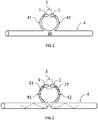
- the lighting system comprises two light sources 1 , 2 .
- these two light sources 1 , 2 emit a directional light and the emitted light beam is intended to illuminate a surface perpendicular thereto.
- the light emitted by at least one of the two light sources 1 , 2 is made a directive.
- the two light sources 1 , 2 are identical.
- the light sources 1 , 2 are light emitting diodes (LEDs).
- the light sources 1 , 2 are laser diodes.
- the light sources 1 , 2 are two white light emitting diodes.
- the light sources 1 and 2 are two quasi-monochromatic light-emitting diodes, each producing a beam of light of the same color or not, for example blue, red, green or any combination of these colors.
- the light sources 1 , 2 are managed by an electronic device 3 , which provides the power supply and the control of the open / closed state of the light sources 1 , 2 .
- the electronic device 3 makes it possible to vary the light intensity emitted by the one or both light sources 1 , 2 .
- the two light sources 1 , 2 are synchronously controlled by the electronic device 3 .
- the lighting system further comprises a light guide 4 , linear linear type, or curved.
- the light guide can be open or closed, for example in a loop.
- the light guide 4 comprises a trunk 40 and two branches 41 , 42 .
- the branches 41 , 42 of the figures 1-3 are included in a single branch 43 .
- the light guide 4 is advantageously made by molding in one piece.
- the branches 41 , 42 are thus formed of a single continuous and homogeneous piece with the trunk 40 of the light guide 4 .
- the trunk 40 may have a circular cross section, oval, square, rectangular.
- the light guide 4 is made of transparent material.
- the light guide 4 is made of glass or a transparent polymeric material.
- the light guide 4 is, in one implementation, polymethyl methacrylate, of which the refractive index is about 1.49.
- the light guide is made of polycarbonate, whose refractive index is of the order of 1.59.
- the light guide 4 is provided with reliefs, such as for example gadroons, for dispersing the light outside the guide.
- the branches 41 , 42 converge at the same point of the trunk 40 of the light guide 4 .
- the branches 41 , 42 come from the same point of the trunk 40 .
- this point is located substantially mid-length of the trunk 40 , the branches 41 , 42 meeting at a point of the trunk 40 which is substantially equidistant from the ends of the trunk 40 .
- trunk 40 when the trunk 40 is of great length, several branches 41 , 42 are placed along this trunk 40 , advantageously at a distance from the ends of the trunk 40 .
- a first light source 1 is arranged facing the free end of the branch 41 of the light guide 4 .
- a second light source 2 is disposed facing the free end of the branch 42 of the light guide 4 .
- the light sources 1 , 2 are arranged so that the face of the free end of the branch 41 , 42 is substantially perpendicular to the direction of the light rays coming from the light sources 1 , 2 .
- the light sources 1 , 2 have an emission axis substantially perpendicular to the face of the free end of the branch 41 , 42 of the light guide 4 , so that the light emitted enters the branch 41 , 42 by this end.
- the two branches 41 , 42 converge at a point on the trunk 40 of the light guide 4 so as to guide the light coming respectively from the light sources 1 , 2 in opposite directions in the trunk 40 .
- the branches 41 , 42 are arranged to guide, by internal reflections, the light rays emitted by the light sources 1 , 2 towards the interior of the trunk 40 of the light guide.
- the rays of light emitted, materialized by the arrows 21 , 22 are propagate in the branches 41 , 42 from their free ends to the inside of the trunk 40 of the light guide 4 .
- the light rays emitted by the light sources 1 , 2 are thus conveyed (or guided) at least partly towards the interior of the trunk 40 at its center and propagated by internal reflections, on both sides of the trunk 40. this medium, in the trunk 40 .
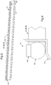
- branches 41 , 42 may have arc-shaped profiles, for example an arc ( figure 1 and 2 ) or in the form of rectilinear segments as illustrated on the figure 3 .
- the branches 41 , 42 of the figures 1-3 are included in a single branch 43 located substantially in the middle of the trunk 40 of the light guide, and the two light sources 1 , 2 are included in a single light source 12 , arranged opposite the free end of the branch 43 .
- the recess in the form of an inverted V made in the trunk 40 facing the branch 43 distributes the light rays carried by this branch 43 in the two parts of the trunk 40 , on either side of the starting point of the branch 43 .
- a cover is provided to cover the electronic device 3 .
- This cover makes it possible to thermally isolate the electronic circuit 3 as well as the light sources 1 , 2 (or 12 ) of the light guide 4 .
- This cover makes it possible to mask the electronic device, for reasons of aesthetics and protection against shocks.
- this cover is, furthermore, provided for orienting the light emitted by the light source 1 , 2 (or 12 ) towards the end of the corresponding branch 41 , 42 (or 43 ) and thus limiting the scattering of light at this level.
- a diffuser 5 is configured to receive the light guide 4 .
- the light guide 4 comprises preferably a plurality of irregularities 44 surface (surface alterations, such as local terrain changes) in order to focus and project the light rays 21, 22 propagating in the trunk 40 on a reflective zone 51 of the diffuser 5 .
- the electronic device 3 and these light sources are advantageously kept at a distance from the light guide 4 , so that they can dissipate the light. thermal energy that they emit far from the light guide 4 .
- the above-described arrangement of the light sources makes it possible to obtain a closed line of light, without there being a discontinuity that would be required when the light source (s) are disposed at one end of the trunk 40. .
- provision of the (or of the) source (s) light at mid length of the light guide 4 makes it possible to obtain a continuous line of light and uniform over the entire length of the guide.
- This arrangement makes it possible to obtain a substantially homogeneous and uniform photometry along the light guide.
- the lighting system shown above can, of course, be used to illuminate at least a part of a interior environment such as that of a motor vehicle, or at least part of an external environment by drawing / signaling, for example, the outer edges of a road, lights, a wagon, or more generally an object.
- the ambient lighting system that has just been described has many other advantages. It can be implemented with a minimum of space and increases the effective or useful length of the light guide.
- the lighting system that has been described finds advantageous application in the ambient lighting of vehicles, especially automobiles.
- the system provides lighting or signaling for vehicles, including motor vehicles, eg ceiling lights, console lighting, a reading light, or even external lighting, such as fire or projectors.
Landscapes
- Engineering & Computer Science (AREA)
- Mechanical Engineering (AREA)
- Physics & Mathematics (AREA)
- General Physics & Mathematics (AREA)
- Optics & Photonics (AREA)
- General Engineering & Computer Science (AREA)
- Arrangements Of Lighting Devices For Vehicle Interiors, Mounting And Supporting Thereof, Circuits Therefore (AREA)
- Planar Illumination Modules (AREA)
Applications Claiming Priority (1)
| Application Number | Priority Date | Filing Date | Title |
|---|---|---|---|
| FR1654477A FR3051539A1 (fr) | 2016-05-19 | 2016-05-19 | Systemes d’eclairage d’ambiance pour vehicules |
Publications (1)
| Publication Number | Publication Date |
|---|---|
| EP3246622A1 true EP3246622A1 (de) | 2017-11-22 |
Family
ID=56511757
Family Applications (1)
| Application Number | Title | Priority Date | Filing Date |
|---|---|---|---|
| EP17170053.7A Withdrawn EP3246622A1 (de) | 2016-05-19 | 2017-05-09 | Raumbeleuchtungssystem für fahrzeuge |
Country Status (3)
| Country | Link |
|---|---|
| EP (1) | EP3246622A1 (de) |
| CN (1) | CN107489954A (de) |
| FR (1) | FR3051539A1 (de) |
Cited By (3)
| Publication number | Priority date | Publication date | Assignee | Title |
|---|---|---|---|---|
| EP3401164A1 (de) * | 2017-05-09 | 2018-11-14 | PSA Automobiles SA | Innenverkleidungsteil eines fahrzeugs mit einer anordnung eines raumbeleuchtungssystems |
| KR20190024124A (ko) * | 2017-08-31 | 2019-03-08 | 에스엘 주식회사 | 차량용 램프 |
| CN109539052A (zh) * | 2019-01-07 | 2019-03-29 | 广州小鹏汽车科技有限公司 | 一种星空氛围灯及其控制方法、汽车 |
Families Citing this family (3)
| Publication number | Priority date | Publication date | Assignee | Title |
|---|---|---|---|---|
| CN108626679B (zh) * | 2018-05-22 | 2024-05-17 | 常州星宇车灯股份有限公司 | 一种基于光导的用于机动车辆的光源组件 |
| IT201900004825A1 (it) * | 2019-04-01 | 2020-10-01 | Olsa Spa | Sistema di illuminazione ambientale per autovetture e relativa autovettura |
| FR3161627B1 (fr) | 2024-04-25 | 2026-03-13 | Stellantis Auto Sas | Dispositif d’éclairage d’ambiance pour véhicule automobile |
Citations (9)
| Publication number | Priority date | Publication date | Assignee | Title |
|---|---|---|---|---|
| FR2828267A3 (fr) | 2001-08-01 | 2003-02-07 | Hella Kg Hueck & Co | "lampe pour vehicule" |
| US6854869B1 (en) | 2002-05-10 | 2005-02-15 | Robert Fernandez | Led fiber optic illuminated vehicle seat cover |
| EP1867913A1 (de) | 2006-06-15 | 2007-12-19 | Valeo Vision | Vorrichtung zur Beleuchtung oder Signalisierung mittels Lichtwellenleiter für Kraftfahrzeuge |
| FR2995971A1 (fr) * | 2012-09-26 | 2014-03-28 | Valeo Vision | Dispositif d'eclairage, notamment pour vehicule automobile. |
| DE102012222684A1 (de) | 2012-12-11 | 2014-06-12 | Bayerische Motoren Werke Aktiengesellschaft | Beleuchtungseinrichtung für ein Kraftfahrzeug |
| US20140247617A1 (en) * | 2009-06-30 | 2014-09-04 | Antoine De Lamberterie | Optical device, in particular for a motor vehicle |
| FR3003928A1 (fr) * | 2013-03-27 | 2014-10-03 | Valeo Vision | Dispositif d'eclairage ou de signalisation pour vehicule automobile |
| US20150023047A1 (en) * | 2012-05-09 | 2015-01-22 | Yazaki Corporation | Light emitting unit |
| EP2955062A2 (de) | 2014-06-11 | 2015-12-16 | Zizala Lichtsysteme GmbH | Beleuchtungsvorrichtung für ein fahrzeug |
-
2016
- 2016-05-19 FR FR1654477A patent/FR3051539A1/fr not_active Ceased
-
2017
- 2017-05-09 EP EP17170053.7A patent/EP3246622A1/de not_active Withdrawn
- 2017-05-19 CN CN201710356997.8A patent/CN107489954A/zh active Pending
Patent Citations (10)
| Publication number | Priority date | Publication date | Assignee | Title |
|---|---|---|---|---|
| FR2828267A3 (fr) | 2001-08-01 | 2003-02-07 | Hella Kg Hueck & Co | "lampe pour vehicule" |
| US6854869B1 (en) | 2002-05-10 | 2005-02-15 | Robert Fernandez | Led fiber optic illuminated vehicle seat cover |
| EP1867913A1 (de) | 2006-06-15 | 2007-12-19 | Valeo Vision | Vorrichtung zur Beleuchtung oder Signalisierung mittels Lichtwellenleiter für Kraftfahrzeuge |
| US20070292101A1 (en) * | 2006-06-15 | 2007-12-20 | Valeo Vision | Lighting or signalling device having an optical guide for a motor vehicle |
| US20140247617A1 (en) * | 2009-06-30 | 2014-09-04 | Antoine De Lamberterie | Optical device, in particular for a motor vehicle |
| US20150023047A1 (en) * | 2012-05-09 | 2015-01-22 | Yazaki Corporation | Light emitting unit |
| FR2995971A1 (fr) * | 2012-09-26 | 2014-03-28 | Valeo Vision | Dispositif d'eclairage, notamment pour vehicule automobile. |
| DE102012222684A1 (de) | 2012-12-11 | 2014-06-12 | Bayerische Motoren Werke Aktiengesellschaft | Beleuchtungseinrichtung für ein Kraftfahrzeug |
| FR3003928A1 (fr) * | 2013-03-27 | 2014-10-03 | Valeo Vision | Dispositif d'eclairage ou de signalisation pour vehicule automobile |
| EP2955062A2 (de) | 2014-06-11 | 2015-12-16 | Zizala Lichtsysteme GmbH | Beleuchtungsvorrichtung für ein fahrzeug |
Cited By (3)
| Publication number | Priority date | Publication date | Assignee | Title |
|---|---|---|---|---|
| EP3401164A1 (de) * | 2017-05-09 | 2018-11-14 | PSA Automobiles SA | Innenverkleidungsteil eines fahrzeugs mit einer anordnung eines raumbeleuchtungssystems |
| KR20190024124A (ko) * | 2017-08-31 | 2019-03-08 | 에스엘 주식회사 | 차량용 램프 |
| CN109539052A (zh) * | 2019-01-07 | 2019-03-29 | 广州小鹏汽车科技有限公司 | 一种星空氛围灯及其控制方法、汽车 |
Also Published As
| Publication number | Publication date |
|---|---|
| FR3051539A1 (fr) | 2017-11-24 |
| CN107489954A (zh) | 2017-12-19 |
Similar Documents
| Publication | Publication Date | Title |
|---|---|---|
| FR3051539A1 (fr) | Systemes d’eclairage d’ambiance pour vehicules | |
| EP2098774B1 (de) | Optisches System mit Hauptfunktion für Kraftfahrzeug | |
| EP2510277B1 (de) | Lanterne oder positionsleuchte für kraftfahrzeugleuchte | |
| FR3070070A1 (fr) | Guide de lumiere en forme de tige et lampe de vehicule | |
| WO2014048848A1 (fr) | Dispositif d'éclairage et/ou de signalisation de véhicule automobile | |
| WO2019158889A1 (fr) | Dispositif de signalisation pour un vehicule automobile | |
| FR2974616A1 (fr) | Dispositif de signalisation avec fonctions "stop" et "position" utilisant un guide de lumiere et generant un effect 3d | |
| FR3030684B1 (fr) | Dispositif lumineux comprenant des sources surfaciques de lumiere | |
| EP2738453A1 (de) | Lichtwellenleiter für eine optische Vorrichtung, insbesondere zur Beleuchtung und/oder Signalisierung | |
| FR3008774A1 (fr) | Systeme d'eclairage, notamment pour un organe d'eclairage de vehicule automobile, a carte a circuit imprime dans le plan de la direction d'eclairage | |
| WO2012098123A1 (fr) | Unite optique pour dispositif de signalisation et/ou d'eclairage | |
| FR3013420A1 (fr) | Systeme d'eclairage et/ou de signalisation avec guides pour vehicule automobile | |
| EP2809985B1 (de) | Vorrichtung zur vereinheitlichung des aussehens von motorfahrzeug-signalleuchten | |
| FR3003928A1 (fr) | Dispositif d'eclairage ou de signalisation pour vehicule automobile | |
| EP3150907A1 (de) | Optische vorrichtung und system zur signalisierung und/oder beleuchtung für kraftfahrzeug | |
| EP2738448A2 (de) | Beleuchtung und/oder Signalisierungsvorrichtung, insbesondere für Fahrzeug | |
| EP2833053B1 (de) | Beleuchtungs- und/oder Signalisierungsvorrichtung, und Scheinwerfereinheit für ein Motorfahrzeug, das diese Vorrichtung umfasst | |
| FR2927404A1 (fr) | Systeme optique avec fonction principale et fonction decorative pour vehicule automobile | |
| WO2014048847A1 (fr) | Dispositif d'éclairage, notamment pour véhicule automobile | |
| EP3728939B1 (de) | Signalleuchte für kraftfahrzeuge mit besserem sehkomfort für die verkehrsteilnehmer | |
| FR2939868A1 (fr) | Systeme optique pour vehicule automobile | |
| JP6901354B2 (ja) | 車両用灯具 | |
| EP3045804B1 (de) | Kraftfahrzeugleuchtvorrichtung mit lichtwellenleiter mit einem nach hinten gekrümmten teil | |
| FR2995969A1 (fr) | Systeme optique de vehicule automobile comprenant une nappe de guidage de lumiere | |
| EP3027964B1 (de) | Beleuchtungs- und/oder signalisierungsvorrichtung für ein fahrzeug, insbesondere ein kraftfahrzeug |
Legal Events
| Date | Code | Title | Description |
|---|---|---|---|
| PUAI | Public reference made under article 153(3) epc to a published international application that has entered the european phase |
Free format text: ORIGINAL CODE: 0009012 |
|
| AK | Designated contracting states |
Kind code of ref document: A1 Designated state(s): AL AT BE BG CH CY CZ DE DK EE ES FI FR GB GR HR HU IE IS IT LI LT LU LV MC MK MT NL NO PL PT RO RS SE SI SK SM TR |
|
| AX | Request for extension of the european patent |
Extension state: BA ME |
|
| STAA | Information on the status of an ep patent application or granted ep patent |
Free format text: STATUS: THE APPLICATION IS DEEMED TO BE WITHDRAWN |
|
| 18D | Application deemed to be withdrawn |
Effective date: 20180523 |