EP3246623B1 - Leuchte mit led-leiterplatte auf blechträger - Google Patents
Leuchte mit led-leiterplatte auf blechträger Download PDFInfo
- Publication number
- EP3246623B1 EP3246623B1 EP17171954.5A EP17171954A EP3246623B1 EP 3246623 B1 EP3246623 B1 EP 3246623B1 EP 17171954 A EP17171954 A EP 17171954A EP 3246623 B1 EP3246623 B1 EP 3246623B1
- Authority
- EP
- European Patent Office
- Prior art keywords
- circuit board
- printed circuit
- sheet metal
- led printed
- luminaire according
- Prior art date
- Legal status (The legal status is an assumption and is not a legal conclusion. Google has not performed a legal analysis and makes no representation as to the accuracy of the status listed.)
- Active
Links
Images


Classifications
-
- F—MECHANICAL ENGINEERING; LIGHTING; HEATING; WEAPONS; BLASTING
- F21—LIGHTING
- F21V—FUNCTIONAL FEATURES OR DETAILS OF LIGHTING DEVICES OR SYSTEMS THEREOF; STRUCTURAL COMBINATIONS OF LIGHTING DEVICES WITH OTHER ARTICLES, NOT OTHERWISE PROVIDED FOR
- F21V19/00—Fastening of light sources or lamp holders
- F21V19/001—Fastening of light sources or lamp holders the light sources being semiconductors devices, e.g. LEDs
- F21V19/003—Fastening of light source holders, e.g. of circuit boards or substrates holding light sources
- F21V19/004—Fastening of light source holders, e.g. of circuit boards or substrates holding light sources by deformation of parts or snap action mountings, e.g. using clips
-
- F—MECHANICAL ENGINEERING; LIGHTING; HEATING; WEAPONS; BLASTING
- F21—LIGHTING
- F21S—NON-PORTABLE LIGHTING DEVICES; SYSTEMS THEREOF; VEHICLE LIGHTING DEVICES SPECIALLY ADAPTED FOR VEHICLE EXTERIORS
- F21S4/00—Lighting devices or systems using a string or strip of light sources
- F21S4/20—Lighting devices or systems using a string or strip of light sources with light sources held by or within elongate supports
- F21S4/28—Lighting devices or systems using a string or strip of light sources with light sources held by or within elongate supports rigid, e.g. LED bars
-
- F—MECHANICAL ENGINEERING; LIGHTING; HEATING; WEAPONS; BLASTING
- F21—LIGHTING
- F21V—FUNCTIONAL FEATURES OR DETAILS OF LIGHTING DEVICES OR SYSTEMS THEREOF; STRUCTURAL COMBINATIONS OF LIGHTING DEVICES WITH OTHER ARTICLES, NOT OTHERWISE PROVIDED FOR
- F21V19/00—Fastening of light sources or lamp holders
- F21V19/001—Fastening of light sources or lamp holders the light sources being semiconductors devices, e.g. LEDs
- F21V19/003—Fastening of light source holders, e.g. of circuit boards or substrates holding light sources
- F21V19/0035—Fastening of light source holders, e.g. of circuit boards or substrates holding light sources the fastening means being capable of simultaneously attaching of an other part, e.g. a housing portion or an optical component
-
- F—MECHANICAL ENGINEERING; LIGHTING; HEATING; WEAPONS; BLASTING
- F21—LIGHTING
- F21V—FUNCTIONAL FEATURES OR DETAILS OF LIGHTING DEVICES OR SYSTEMS THEREOF; STRUCTURAL COMBINATIONS OF LIGHTING DEVICES WITH OTHER ARTICLES, NOT OTHERWISE PROVIDED FOR
- F21V5/00—Refractors for light sources
- F21V5/007—Array of lenses or refractors for a cluster of light sources, e.g. for arrangement of multiple light sources in one plane
-
- F—MECHANICAL ENGINEERING; LIGHTING; HEATING; WEAPONS; BLASTING
- F16—ENGINEERING ELEMENTS AND UNITS; GENERAL MEASURES FOR PRODUCING AND MAINTAINING EFFECTIVE FUNCTIONING OF MACHINES OR INSTALLATIONS; THERMAL INSULATION IN GENERAL
- F16B—DEVICES FOR FASTENING OR SECURING CONSTRUCTIONAL ELEMENTS OR MACHINE PARTS TOGETHER, e.g. NAILS, BOLTS, CIRCLIPS, CLAMPS, CLIPS OR WEDGES; JOINTS OR JOINTING
- F16B17/00—Connecting constructional elements or machine parts by a part of or on one member entering a hole in the other and involving plastic deformation
- F16B17/008—Connecting constructional elements or machine parts by a part of or on one member entering a hole in the other and involving plastic deformation of sheets or plates mutually
-
- F—MECHANICAL ENGINEERING; LIGHTING; HEATING; WEAPONS; BLASTING
- F16—ENGINEERING ELEMENTS AND UNITS; GENERAL MEASURES FOR PRODUCING AND MAINTAINING EFFECTIVE FUNCTIONING OF MACHINES OR INSTALLATIONS; THERMAL INSULATION IN GENERAL
- F16B—DEVICES FOR FASTENING OR SECURING CONSTRUCTIONAL ELEMENTS OR MACHINE PARTS TOGETHER, e.g. NAILS, BOLTS, CIRCLIPS, CLAMPS, CLIPS OR WEDGES; JOINTS OR JOINTING
- F16B5/00—Joining sheets or plates, e.g. panels, to one another or to strips or bars parallel to them
- F16B5/04—Joining sheets or plates, e.g. panels, to one another or to strips or bars parallel to them by means of riveting
- F16B5/045—Joining sheets or plates, e.g. panels, to one another or to strips or bars parallel to them by means of riveting without the use of separate rivets
-
- F—MECHANICAL ENGINEERING; LIGHTING; HEATING; WEAPONS; BLASTING
- F21—LIGHTING
- F21V—FUNCTIONAL FEATURES OR DETAILS OF LIGHTING DEVICES OR SYSTEMS THEREOF; STRUCTURAL COMBINATIONS OF LIGHTING DEVICES WITH OTHER ARTICLES, NOT OTHERWISE PROVIDED FOR
- F21V15/00—Protecting lighting devices from damage
- F21V15/01—Housings, e.g. material or assembling of housing parts
-
- F—MECHANICAL ENGINEERING; LIGHTING; HEATING; WEAPONS; BLASTING
- F21—LIGHTING
- F21V—FUNCTIONAL FEATURES OR DETAILS OF LIGHTING DEVICES OR SYSTEMS THEREOF; STRUCTURAL COMBINATIONS OF LIGHTING DEVICES WITH OTHER ARTICLES, NOT OTHERWISE PROVIDED FOR
- F21V19/00—Fastening of light sources or lamp holders
- F21V19/001—Fastening of light sources or lamp holders the light sources being semiconductors devices, e.g. LEDs
- F21V19/003—Fastening of light source holders, e.g. of circuit boards or substrates holding light sources
- F21V19/005—Fastening of light source holders, e.g. of circuit boards or substrates holding light sources by permanent fixing means, e.g. gluing, riveting or embedding in a potting compound
-
- F—MECHANICAL ENGINEERING; LIGHTING; HEATING; WEAPONS; BLASTING
- F21—LIGHTING
- F21Y—INDEXING SCHEME ASSOCIATED WITH SUBCLASSES F21K, F21L, F21S and F21V, RELATING TO THE FORM OR THE KIND OF THE LIGHT SOURCES OR OF THE COLOUR OF THE LIGHT EMITTED
- F21Y2103/00—Elongate light sources, e.g. fluorescent tubes
- F21Y2103/10—Elongate light sources, e.g. fluorescent tubes comprising a linear array of point-like light-generating elements
-
- F—MECHANICAL ENGINEERING; LIGHTING; HEATING; WEAPONS; BLASTING
- F21—LIGHTING
- F21Y—INDEXING SCHEME ASSOCIATED WITH SUBCLASSES F21K, F21L, F21S and F21V, RELATING TO THE FORM OR THE KIND OF THE LIGHT SOURCES OR OF THE COLOUR OF THE LIGHT EMITTED
- F21Y2115/00—Light-generating elements of semiconductor light sources
- F21Y2115/10—Light-emitting diodes [LED]
Definitions
- the present invention relates to a luminaire with a printed circuit board, on which one or more LEDs are arranged as lighting means of the luminaire.
- the invention relates to the manner of mounting the LED circuit board in the luminaire.
- Sheet metal housings are very common in luminaire construction because they are robust and can be produced inexpensively.
- the attachment of the bulbs is usually carried out by screwing on corresponding bulb sockets.
- LEDs which means any semiconductor light source including organic LEDs
- printed circuit boards on which the LEDs are arranged also on the sheet metal housing by conventional fastening means, in particular by tapping screws or rivets, to install.
- Object of the present invention is an inexpensive variant for mounting LED circuit boards in sheet metal housings to provide, which also allows a good thermal coupling of the circuit board to the housing.
- a special feature of the mounting of the LED circuit board on the support of sheet metal of the present invention is that no separate fastening means for forming the attachment are necessary. Only the sheet metal sections formed from the carrier are sufficient to hold the circuit board to the carrier. Although this connection is not easily solvable after attaching. However, this is usually not necessary for printed circuit boards with LEDs, since the life expectancy of the LED bulbs is so high that these bulbs, unlike conventional bulbs on the expected life expectancy of the lamp need not be replaced. Further, the attachment according to the present invention makes it possible to mount the printed circuit board with the LEDs directly in close contact with the carrier.
- the opening can be specified from any point on the circuit board.
- the opening may also be formed as a recess on the edge of the circuit board.
- the sheet metal section has at least one metal tongue.
- the metal tongue can be formed by a simple bending dance process from the sheet of the carrier so that the metal tongue remains connected at least along one edge with the rest of the plate of the wearer. By bending the tongue at the free end over the edge of the opening of the circuit board, the attachment of the circuit board is closed.
- the sheet metal section comprises a plurality of continuous or discontinuous subsections, ie subsections which are connected to one another or by flat sections of the sheet metal carrier from each other are separated.
- the sections engage around opposite edge portions of the opening.
- This embodiment has the advantage that the printed circuit board is held tangentially to the surface of the carrier by the opposing sections at the edge of the opening in two opposite directions.
- the circuit board can already be fixed to the carrier by an opening in the circuit board alone.
- a plurality of openings may also be present in the printed circuit board, through which at least one partial section of the sheet metal section extends in each case and is bent around the edge of the respective opening.
- the printed circuit board can be fixed relative to the carrier in possibly a plurality of tangential directions with respect to the surface of the carrier.
- the plurality of sections may be formed by a plurality of opposing sheet metal tongues. These can preferably be bent out of the carrier in a single bending punching process.
- the sections are formed by a continuous cylindrical portion which extends along the edge of the opening therethrough and is recalculated on the opposite side of the contact surface of the circuit board.
- a cylindrical portion is pressed out of the support made of sheet metal in the direction of the board, the board plugged with the opening on the cylindrical portion and the cylindrical portion bent over the circuit board to the outside.
- This compound looks like a hollow rivet on the side facing away from the carrier.
- no separate rivet is used, but according to the invention the compound is formed solely by the material of the sheet metal carrier.
- the printed circuit board lies flat against the carrier.
- an electrical insulating layer may be provided between the carrier and the printed circuit board when the printed circuit board has live parts on the side facing the carrier.
- the printed circuit board is preferably insulated directly or has no voltage-carrying parts on the side facing the carrier. Possibly. may also be provided between the carrier and the circuit board, a thermal paste or foil.
- the carrier is a part of a lamp housing formed from sheet metal.
- the circuit board can be mounted directly on the lamp housing, for example, at the bottom portion of the lamp housing, which is arranged opposite the light exit surface.
- the sheet of the carrier has a material thickness of 0.4 mm to 2 mm, in particular from 0.5 mm to 1 mm.
- These material thicknesses are larger than a dimension usually used for a lamp housing sheet metal.
- this large plate thickness has the advantage that sufficient material is available to not only form the connection, but also to ensure the heat transfer from the LEDs into the housing.
- the carrier or the entire housing is therefore not only used for mechanical attachment of the LED circuit board but also as a heat sink for the LED circuit board.
- the circuit board is fixed to the carrier, without the use of others Fastening means except the one or more formed from sheet metal of the carrier sheet metal sections. It has been found that the attachment through the sheet metal sections is completely sufficient to fix the circuit board. Further fasteners such as screws or rivets are therefore unnecessary.
- an additional lighting component is arranged on the side facing away from the carrier of the circuit board, which is held together with the circuit board by means of the sheet metal section.
- additional luminaire components which must be precisely aligned with the bulbs arranged on the circuit board, e.g. a lens plate with individual lenses, which must be aligned to the LEDs
- the additional lighting component engages with one or more feet in each case one of the openings of the printed circuit board and is held there together with the printed circuit board by the sheet metal section by the sheet metal section is bent over the foot.
- the circuit board is supported only at longitudinal edges, such that a longitudinal extension of the circuit board relative to the carrier is possible.
- the openings in the form of cutouts on the circuit board may be formed so that they have a slightly larger dimension in the longitudinal direction than the length of the sheet metal section engaging therein.
- the printed circuit board it is possible for the printed circuit board to expand longitudinally independently of the carrier. This is particularly advantageous for particularly long printed circuit boards in linear luminaires, which can be produced more cheaply if they are manufactured in one piece.
- a problem with fixing by fixed Screwing or riveting is that the circuit board can not extend independently of the carrier in the longitudinal direction, which can lead to thermally induced distortions during operation of the lamp. This problem is overcome in the preferred embodiment by means of attachment to the longitudinal edges.
- FIGS. 1 to 5 A first embodiment will be described.
- a luminaire comprises a carrier 2, which is formed from sheet metal, preferably from a bottom portion of a lamp housing, and a printed circuit board 4, which is arranged thereon.
- the printed circuit board 4 has a plurality of LEDs 6, which are arranged along a row in the embodiment shown.
- first sheet metal sections 10 are punched out of the carrier by means of a punching / bending process and bent out in the direction of the contact surface on which the circuit board 4 is to be placed on the carrier.
- FIGS. 4 and 5 show the sheet metal sections 10 in the form of two sheet metal tongues, which are punched out of the carrier 2 approximately along each of a semicircle and are bent out along each of a straight edge of the plane of the carrier 2.
- the printed circuit board 4 is placed on the carrier 2, so that the sheet metal sections 10 extend through an opening 12 in the circuit board 4. Subsequently, the sheet metal sections 10 are bent to the outside, so that they surround the edge of the opening 12 on the side facing away from the carrier of the circuit board 4. As a result, a positive fastening of the printed circuit board 4 is formed on the carrier 2. Since the sheet metal portion 10 includes two opposing tongues, the printed circuit board 4 can not move in any direction parallel to the surface of the carrier 2. Theoretically, the circuit board 4 could still rotate around the sheet metal sections of the attachment. However, this is precluded by the fact that either further of the previously described fasteners are provided on the carrier, or that the printed circuit board 4 rests on at least one edge on the carrier 2, so that a rotation is prevented.
- the sheet metal portion 10 comprises no single tongues but a continuous cylindrical portion which is pushed out of the material of the carrier 2 in the direction of the contact surface on which the printed circuit board 4 is applied.
- the circuit board 4 has the same opening 12 as explained in the previously described embodiment. With this opening 12, the circuit board 4 is inserted over the cylindrical portion 10 'of the carrier. Subsequently, the cylindrical portion 10 'on the side facing away from the carrier 2 of the circuit board 4 is umbörtelt. For example, with a ball whose diameter is slightly larger than the diameter of the cylindrical portion 10 ', the edge of the cylindrical portion 10' are uniformly turned over to the outside by pressing the ball.
- FIGS. 8 to 10 A further alternative embodiment of the luminaire is described, the same reference numerals as previously used being used for corresponding features.
- the printed circuit boards are elongated with e.g. a row or a double row of LEDs 6.
- the openings 12 are provided in the form of cutouts at the edge. In each of these cutouts, a sheet metal section 10, which is bent out of the lying below the circuit board 4 plate carrier 2.
- the printed circuit boards 4 are held only at the longitudinal edges, wherein the cutout 12 is slightly longer than the sheet metal section 10, so that the circuit boards 4 can expand independently of the underlying support 2 with thermal heating. This has an advantage especially when using very long printed circuit boards in linear luminaires. A long continuous circuit board 4 is cheaper to manufacture.
- the openings 12 in the form of cutouts at the longitudinal edges have the advantage that the circuit board itself is not interrupted, so that no structural or color differences are to be perceived on the light exit side.
- an additional lighting component in the form of a lens cover 14 is arranged on the printed circuit board 4 directly above the LEDs 6.
- the lens cover 14 has individual lens elements associated with one or a group of LEDs 6, respectively.
- the lens cover 14 is fastened by means of the same sheet metal sections 10 as the printed circuit board 4.
- the lens cover has feet 16, which are formed in the form of a bend in the direction of the carrier 2.
- the feet 16 engage in each case an opening 12 of the circuit board 4 adjacent to the sheet metal section 10, wherein the sheet metal portion 10 is bent over the foot 16, so that both the lens cover 14 and the circuit board 4 is held by the sheet metal portion 10 on the support 2.
- At least one further positioning foot 18 can be provided on the lens cover 14 or any other additional lighting component, which also engages in an opening 12 of the printed circuit board.
- the positioning foot is not secured with a sheet metal portion 10 of the carrier, but is only with the circuit board 4 in connection.
- the positioning foot 18 can fit precisely into the printed circuit board in order to position the lens cover or another additional lighting component 14 with respect to the LEDs 6.
- the lens cover 14 can move along with the printed circuit board 14 during thermal expansion, so that the alignment of the lenses with respect to the LEDs is maintained even with a different thermal expansion relative to the carrier 2.
- some of the sheet metal sections 10 can engage in openings 12 of the printed circuit board 4 without attacking the additional lighting component 14.
- a positioning foot 18 may engage a side cutout of the circuit board to position a light cover, while on the opposite side a shorter sheet section 10 engages a cutout 12 of the circuit board to hold the circuit board.
- FIG. 10 illustrated embodiment, different circuit boards 4, each with the same lighting components, as previously described, are connected.
- two different circuit boards 4 are shown, with a narrower version only one single row of LEDs 6, while the wider version has a double row of LEDs 6.
- the carrier 2 and the lens cover 14 can remain the same, so that a system of different lights can be formed from partially identical components.
- FIG. 10 is understood that only one of the two printed circuit boards 4 shown one above the other is used in the lamp.
- the different widths of printed circuit boards 4 can interact with the same sheet metal portion 10 of the support 2, the cutouts 12 are configured T-shaped in the wider circuit board 4 to engage deeper in the circuit board 4, compared to the simple cutouts 12 in the narrower Printed circuit board 4.
- a terminal 20 is provided on the circuit board 4, which engages in an opening 22 of the carrier in order to be contacted by the opposite side can.
- the opening 22 does not have a sheet portion protruding from the opening 22 toward the circuit board. The opening 22 is completely punched out.
- more than two tongues may be provided as sheet metal sections. There may be three or more tongues along a circumference of the circumference, each bent outwardly around the circuit board. The tongues can each engage individually through an opening of the circuit board or more than two tongues reach through an opening.
- the opening in the circuit board may, but need not, be circular.
Landscapes
- Engineering & Computer Science (AREA)
- General Engineering & Computer Science (AREA)
- Fastening Of Light Sources Or Lamp Holders (AREA)
- Arrangement Of Elements, Cooling, Sealing, Or The Like Of Lighting Devices (AREA)
- Non-Portable Lighting Devices Or Systems Thereof (AREA)
Description
- Die vorliegende Erfindung betrifft eine Leuchte mit einer Leiterplatte, auf der eine oder mehrere LEDs als Leuchtmittel der Leuchte angeordnet sind. Insbesondere betrifft die Erfindung die Art der Befestigung der LED-Leiterplatte in der Leuchte.
- Im Leuchtenbau sind Blechgehäuse sehr gängig, weil sie robust sind und kostengünstig herstellbar sind. Die Befestigung der Leuchtmittel erfolgt üblicherweise durch Anschrauben von entsprechenden Leuchtmittelfassungen.
- Im Hinblick auf moderendere Leuchtmittel, welche durch LEDs (worunter jede Halbleiterlichtquelle einschließlich organischer LEDs zu verstehen ist) gebildet sind, ist es üblich, Leiterplatten, auf denen die LEDs angeordnet sind, ebenfalls an dem Blechgehäuse durch herkömmliche Befestigungsmittel, insbesondere durch Blechschrauben oder Nieten, anzubringen.
- Diese Befestigungsmittel sind jedoch relativ aufwendig anzubringen und für die Massenproduktion vergleichsweise kostenintensiv. Ferner kann sich leicht ein Spalt zwischen der Leiterplatte und dem Gehäuse bilden, wodurch sich die thermische Kopplung der Bauteile verschlechtert.
-
DE 20 2014 100 952 U1 offenbart eine Leuchte gemäß dem Oberbegriff des Anspruchs 1. - Aufgabe der vorliegenden Erfindung ist es, eine kostengünstige Variante zur Befestigung von LED-Leiterplatten in Blechgehäusen bereitzustellen, welche auch eine gute thermische Ankopplung der Leiterplatte an das Gehäuse ermöglicht.
- Die Erfindung wird gelöst durch den Gegenstand nach Anspruch 1.
- Eine Besonderheit der Befestigung der LED-Leiterplatte auf dem Träger aus Blech der vorliegenden Erfindung besteht darin, dass keine separaten Befestigungsmittel zur Ausbildung der Befestigung notwendig sind. Alleine die aus dem Träger gebildeten Blechabschnitte genügen, um die Leiterplatte an dem Träger festzuhalten. Diese Verbindung ist zwar nach dem Befestigen nicht mehr ohne weiteres lösbar. Dies ist jedoch für Leiterplatten mit LED in der Regel auch nicht notwendig, da die Lebenserwartung der LED-Leuchtmittel so hoch ist, dass diese Leuchtmittel im Unterschied zu herkömmlichen Leuchtmitteln über die voraussichtliche Lebenserwartung der Leuchte nicht ausgetauscht werden müssen. Ferner ermöglicht es die Befestigung gemäß der vorliegenden Erfindung, die Leiterplatte mit den LEDs direkt in engem Kontakt auf dem Träger anzubringen. Dadurch ist auch eine gute thermische Verbindung zwischen der Leiterplatte und dem Träger aus Blech gewährleistet, so dass der Blechträger zum Ableiten der Wärme dienen kann, die beim Betrieb der LEDs entsteht. Die Öffnung kann von jeder Stelle der Leiterplatte vorgegeben sein. Die Öffnung kann auch als Aussparung am Rand der Leiterplatte gebildet sein.
- Gemäß einer bevorzugten Ausführungsform weist der Blechabschnitt wenigstens eine Metallzunge auf. Die Metallzunge lässt sich durch einen einfachen Biegestanzprozess aus dem Blech des Trägers so ausbilden, dass die Metallzunge wenigstens entlang einer Kante mit dem übrigen Blech des Trägers noch verbunden bleibt. Durch Umbiegen der Zunge am freien Ende über den Rand der Öffnung der Leiterplatte wird die Befestigung der Leiterplatte geschlossen.
- In einer bevorzugten Ausführungsform umfasst der Blechabschnitt mehrere kontinuierliche oder diskontinuierliche Teilabschnitte, d.h. Teilabschnitte, die miteinander verbunden sind oder durch ebene Abschnitte des Blechträgers voneinander getrennt sind. Die Teilabschnitte umgreifen gegenüberliegende Randabschnitte der Öffnung. Diese Ausführungsform hat den Vorteil, dass die Leiterplatte durch die gegenüberliegenden Teilabschnitte am Rand der Öffnung in zwei entgegengesetzten Richtungen tangential zur Oberfläche des Trägers gehalten wird. Dadurch kann alleine durch eine Öffnung in der Leiterplatte bereits die Leiterplatte an dem Träger festgelegt werden. Alternativ oder zusätzliche können auch mehrere Öffnungen in der Leiterplatte vorhanden sein, durch die sich jeweils wenigstens ein Teilabschnitt des Blechabschnitts erstreckt und um den Rand der jeweiligen Öffnung umgebogen ist. Auch in dieser Ausführungsform kann die Leiterplatte gegenüber dem Träger in ggf. mehrere Tangentialrichtungen gegenüber der Oberfläche des Trägers festgelegt werden.
- Gemäß einer Weiterbildung der vorhergehend genannten Ausführungsform können die mehreren Teilabschnitte durch mehrere gegenüberliegende Blechzungen gebildet sein. Diese lassen sich vorzugsweise in einem einzigen Biegestanzprozess aus dem Träger herausbiegen.
- Gemäß einer alternativen Ausführungsform kann vorgesehen sein, dass die Teilabschnitte durch einen kontinuierlichen zylinderförmigen Bereich gebildet sind, der sich entlang des Randes der Öffnung durch diese erstreckt und auf der der Anlagefläche entgegengesetzten Seite der Leiterplatte umbörtelt ist. In dieser Ausführungsform wird ein zylinderförmiger Abschnitt aus dem Träger aus Blech in Richtung zur Platine herausgedrückt, die Platine mit der Öffnung auf den zylinderförmigen Abschnitt aufgesteckt und der zylinderförmige Abschnitt nach außen über der Leiterplatte umgebogen. Diese Verbindung sieht auf der dem Träger abgewandten Seite wie eine Hohlniete aus. Im Unterschied zu einer Nietverbindung wird jedoch keine separate Niete verwendet, sondern erfindungsgemäß wird die Verbindung alleine durch das Material des Blechträgers gebildet.
- Gemäß einer bevorzugten Ausführungsform liegt die Leiterplatte flächig an dem Träger an. Gegebenenfalls kann eine elektrische Isolierschicht zwischen dem Träger und der Leiterplatter vorgesehen sein, wenn die Leiterplatte auf der zum Träger weisenden Seite spannungsführende Teile aufweist. Vorzugsweise ist die Leiterplatter direkt isolierst oder weist auf der zum Träger weisenden Seite keine Spannungsführenden Teile auf. Ggf. kann auch eine Wärmeleitpaste oder -folie zwischen dem Träger und der Leiterplatte vorgesehen sein. Diese Ausführungsformen haben den Vorteil, dass die Leiterplatte in gutem thermischen Kontakt zu dem Träger gebracht ist, so dass die Wärme der LED über das Blech des Trägers abgeführt werden kann.
- Gemäß einer bevorzugten Ausführungsform ist der Träger ein Teil eines aus Blech gebildeten Leuchtengehäuses. In dieser Ausführungsform kann die Leiterplatte direkt an das Leuchtengehäuse angebracht werden, beispielsweise am Bodenabschnitt des Leuchtengehäuses, welches gegenüberliegend der Lichtaustrittsfläche angeordnet ist.
- Vorzugsweise weist das Blech des Trägers eine Materialstärke von 0,4 mm bis 2 mm, insbesondere von 0,5 mm bis 1 mm, auf. Diese Materialstärken sind größer dimensioniert als ein für ein Leuchtengehäuse üblicherweise verwendetes Blech. Diese große Blechstärke hat jedoch den Vorteil, dass genügend Material zur Verfügung steht, um nicht nur die Verbindung auszubilden, sondern um außerdem den Wärmetransport von den LEDs in das Gehäuse zu gewährleisten. In dieser Ausführungsform dient der Träger bzw. das gesamte Gehäuse daher nicht nur zur mechanischen Befestigung der LED-Leiterplatte sondern gleichzeitig auch als Kühlkörper für die LED-Leiterplatte.
- Gemäß einer bevorzugten Ausführungsform ist die Leiterplatte an dem Träger befestigt, ohne für die Verwendung von weiteren Befestigungsmitteln außer dem einem oder dem mehreren aus Blech des Trägers gebildeten Blechabschnitte. Es hat sich gezeigt, dass die Befestigung durch die Blechabschnitte vollkommen ausreichend ist, um die Leiterplatte festzulegen. Weitere Befestigungsmittel wie Schrauben oder Nieten sind daher entbehrlich.
- Erfindungsgemäß ist auf der dem Träger abgewandten Seite der Leiterplatte ein zusätzliches Leuchtenbauteil angeordnet, welches zusammen mit der Leiterplatte mittels des Blechabschnitts gehalten ist. Insbesondere für zusätzliche Leuchtenbauteile, welche präzise zu den auf der Leiterplatte angeordneten Leuchtmitteln ausgerichtet sein müssen, z.B. eine Linsenplatte mit einzelnen Linsen, die zu den LEDs ausgerichtet sein müssen, ist es von Vorteil, die Leiterplatte zusammen mit den zusätzlichen Leuchtenbauteil zu befestigen. Die Befestigungen durch die Blechabschnitte sind dazu geeignet. Gemäß einer bevorzugten Ausführungsform greift das zusätzliche Leuchtenbauteil mit einem oder mehreren Füßen in jeweils eine der Öffnungen der Leiterplatte ein und wird dort zusammen mit der Leiterplatte durch den Blechabschnitt gehalten, indem der Blechabschnitt über den Fuß umgebogen wird.
- Gemäß einer weiteren Ausführungsform ist die Leiterplatte nur an Längsrändern gehaltert, derart, dass eine Längsausdehnung der Leiterplatte gegenüber dem Träger möglich ist. Beispielsweise können die Öffnungen in Form von Ausschnitten an der Leiterplatte so gebildet sein, dass sie in Längsrichtung eine etwas größere Abmessung aufweisen, als die Länge des darin eingreifenden Blechabschnitts. Dadurch ist es möglich, dass sich die Leiterplatte in Längsrichtung unabhängig von dem Träger ausdehnen kann. Dies ist insbesondere von Vorteil für besonders lange Leiterplatten in Langfeldleuchten, welche kostengünstiger hergestellt werden können, wenn sie in einem Stück gefertigt sind. Ein Problem bei der Fixierung durch feste Schrauben oder Nieten ist jedoch, dass die Leiterplatte sich nicht unabhängig von dem Träger in Längsrichtung ausdehnen kann, wodurch es im Betrieb der Leuchte zu thermisch induzierten Verwerfungen kommen kann. Dieses Problem wird in der bevorzugten Ausführungsform mittels der Befestigung an den Längsrändern überwunden.
- Weitere Merkmale und Vorteile der vorliegenden Erfindung werden aus der nachfolgenden Beschreibung bevorzugter Ausführungsformen deutlich, die in Verbindung mit den Figuren gegeben wird. In den Figuren ist Folgendes dargestellt:
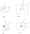
- Figur 1
- zeigt eine perspektivische Teilansicht eines Trägers mit darauf befestigter Leiterplatte.
- Figur 2
- zeigt einen Ausschnitt der
Figur 1 im Bereich der Befestigung. - Figur 3
- zeigt eine Aufsicht auf den Ausschnitt nach
Figur 2 . - Figur 4
- zeigt eine perspektivische Ansicht entsprechend der
Figur 2 , jedoch bevor die Leiterplatte angeordnet ist. - Figur 5
- zeigt eine Aufsicht auf den Bereich der
Figur 4 . - Figur 6
- zeigt einen perspektivischen Teilansicht eines Trägers mit darauf befestigter Leiterplatte für eine alternative Ausführungsform.
- Figur 7
- zeigt eine Aufsicht auf den Ausschnitt nach
Figur 6 . - Figur 8
- zeigt eine Aufsicht auf eine Leuchte einer alternativen Ausführungsform.
- Figur 9
- zeigt eine perspektivische teilweise auseinandergezogene Ansicht der Leuchte nach
Figur 8 . - Figur 10
- zeigt eine perspektivische Teilansicht der Leuchte nach
Figur 8 und 9 mit einer alternativen Leiterplatte. - Bezugnehmend auf die
Figuren 1 bis 5 wird eine erste Ausführungsform beschrieben. - Eine Leuchte umfasst einen Träger 2, welcher aus Blech, vorzugsweise aus einem Bodenabschnitt eines Leuchtengehäuses, gebildet ist, sowie eine Leiterplatte 4, die darauf angeordnet ist. Die Leiterplatte 4 weist eine Vielzahl von LEDs 6 auf, die in der gezeigten Ausführungsform entlang einer Reihe angeordnet sind.
- Bevor die Leiterplatte 4 auf den Träger 2 montiert wird, werden zunächst mittels eines Stanz-/Biege-Prozesses Blechabschnitte 10 aus dem Träger ausgestanzt und in Richtung der Anlagefläche, auf welcher die Leiterplatte 4 auf den Träger aufgelegt werden soll, herausgebogen.
-
Figur 4 und 5 zeigen die Blechabschnitte 10 in Form von zwei Blechzungen, die aus dem Träger 2 etwa entlang jeweils eines Halbkreises ausgestanzt sind und entlang jeweils einer geraden Kante aus der Ebene des Trägers 2 herausgebogen sind. - Im nächsten Arbeitsschritt wird die Leiterplatte 4 auf den Träger 2 aufgelegt, so dass sich die Blechabschnitte 10 durch eine Öffnung 12 in der Leiterplatte 4 erstrecken. Anschließend werden die Blechabschnitte 10 nach außen umgebogen, so dass sie den Rand der Öffnung 12 auf der dem Träger abgewandten Seite der Leiterplatte 4 umgreifen. Dadurch ist eine formschlüssige Befestigung der Leiterplatte 4 auf dem Träger 2 gebildet. Da der Blechabschnitt 10 zwei gegenüberliegende Zungen umfasst, kann sich die Leiterplatte 4 in keine Richtung parallel zur Oberfläche des Trägers 2 bewegen. Theoretisch könnte sich die Leiterplatte 4 noch um die Blechabschnitte der Befestigung drehen. Dies wird jedoch dadurch ausgeschlossen, dass entweder noch weitere der vorhergehend beschriebenen Befestigungen an dem Träger vorgesehen sind, oder dass die Leiterplatte 4 an wenigstens einer Kante an dem Träger 2 anliegt, so dass ein Verdrehen verhindert wird.
- Mit Bezug auf die
Figuren 6 und 7 wird eine alternative Ausführungsform beschrieben. Bei dieser Ausführungsform umfasst der Blechabschnitt 10' keine einzelnen Zungen sondern einen kontinuierlichen zylinderförmigen Abschnitt, welcher aus dem Material des Trägers 2 in Richtung zu der Anlagefläche, an welcher die Leiterplatte 4 angelegt wird, herausgedrückt ist. Die Leiterplatte 4 weist die gleiche Öffnung 12 auf, wie in der vorhergehend beschriebenen Ausführungsform erläutert. Mit dieser Öffnung 12 wird die Leiterplatte 4 über dem zylinderförmigen Abschnitt 10' des Trägers gesteckt. Anschließend wird der zylinderförmige Abschnitt 10' auf der dem Träger 2 abgewandten Seite der Leiterplatte 4 umbörtelt. Beispielsweise kann mit einer Kugel, deren Durchmesser etwas größer ist als der Durchmesser des zylinderförmigen Abschnitts 10', der Rand des zylinderförmigen Abschnitts 10' durch Andrücken der Kugel gleichmäßig nach außen umbörtelt werden. Dadurch ist eine Art Nietverbindung gebildet, welche die Leiterpatte 4 an dem Träger 2 hält. Wie vorhergehend beschrieben, könnte sich unter Umständen die Leiterplatte um den zylinderförmigen Abschnitt 10' noch drehen. Dies kann jedoch dadurch verhindert werden, dass mehrere der vorhergehend beschriebenen Befestigungen an der Leiterplatte 4 vorgesehen sind, oder dass die Leiterplatte 4 mit einem Rand an dem Träger anliegt, so dass ein Drehen verhindert wird. - Bezugnehmend auf die
Figuren 8 bis 10 wird eine weitere alternative Ausführungsform der Leuchte beschrieben, wobei die gleichen Bezugszeichen, wie vorhergehend benutzt, für entsprechende Merkmale verwendet werden. - In dieser Ausführungsform sind die Leiterplatten länglich mit z.B. einer Reihe oder einer Doppelreihe von LEDs 6. An den Längsrändern der Leiterplatten 4 sind die Öffnungen 12 in Form von Ausschnitten am Rand vorgesehen. In diese Ausschnitte greifen jeweils ein Blechabschnitt 10 ein, welcher aus dem unter der Leiterplatte 4 liegenden Blechträger 2 herausgebogen ist. Die Leiterplatten 4 werden nur an den Längsrändern gehalten, wobei der Ausschnitt 12 etwas länger als der Blechabschnitt 10 ist, so dass sich bei thermischer Erwärmung die Leiterplatten 4 unabhängig von dem darunterliegenden Träger 2 ausdehnen können. Dies hat einen Vorteil insbesondere bei Verwendung von sehr langen Leiterplatten in Langfeldleuchten. Eine lange durchgehende Leiterplatte 4 ist kostengünstiger herzustellen. Ferner haben die Öffnungen 12 in Form von Ausschnitte an den Längsrändern den Vorteil, dass die Leiterplatte selbst nicht unterbrochen ist, so dass auf der Lichtaustrittsseite keine strukturellen oder farblichen Unterschiede wahrzunehmen sind.
- Gemäß der Ausführungsform nach
Figur 8 bis 10 ist ferner ein zusätzliches Leuchtenbauteil in Form einer Linsenabdeckung 14 auf der Leiterplatte 4 direkt über den LEDs 6 angeordnet. Die Linsenabdeckung 14 weist einzelne Linsenelemente auf, die jeweils einer oder einer Gruppe von LEDs 6 zugeordnet ist. - Die Linsenabdeckung 14 ist mittels der gleichen Blechabschnitte 10 befestigt wie die Leiterplatte 4. Dazu weist die Linsenabdeckung Füße 16 auf, welche in Form einer Abwinkelung in Richtung zu dem Träger 2 gebildet sind. Die Füße 16 greifen in jeweils eine Öffnung 12 der Leiterplatte 4 neben dem Blechabschnitt 10 ein, wobei der Blechabschnitt 10 über dem Fuß 16 umgebogen wird, so dass sowohl die Linsenabdeckung 14 als auch die Leiterplatte 4 durch den Blechabschnitt 10 an dem Träger 2 gehalten wird.
- Ferner kann an der Linsenabdeckung 14 oder jedem anderen zusätzlichen Leuchtenbauteil noch wenigstens ein weiterer Positionierungsfuß 18 vorgesehen sein, der ebenfalls in eine Öffnung 12 der Leiterplatte eingreift. Der Positionierungsfuß wird jedoch nicht mit einem Blechabschnitt 10 des Trägers gesichert, sondern ist nur mit der Leiterplatte 4 in Verbindung. Dadurch kann der Positionierungsfuß 18 passgenau in die Leiterplatte eingreifen, um die Linsenabdeckung oder ein anderes zusätzliches Leuchtenbauteil 14 gegenüber den LEDs 6 zu positionieren. Die Linsenabdeckung 14 kann sich bei thermischer Ausdehnung zusammen mit der Leiterplatte 14 mitbewegen, so dass die Ausrichtung der Linsen gegenüber den LEDs auch bei einer unterschiedlichen thermischen Ausdehnung gegenüber dem Träger 2 erhalten bleibt.
- Ferner können auch in dieser Ausführungsform einige der Blechabschnitte 10 in Öffnungen 12 der Leiterplatte 4 eingreifen, ohne an dem zusätzlichen Leuchtenbauteil 14 anzugreifen. Beispielsweise kann an einer Seite der Platine 14 ein Positionierungsfuß 18 in einen seitlichen Ausschnitt der Leiterplatte eingreifen, um eine Leuchtenabdeckung zu positionieren, während auf der gegenüberliegenden Seite ein kürzerer Blechabschnitt 10 in einen Ausschnitt 12 der Leiterplatte eingreift, um die Leiterplatte zu halten.
- Gemäß einer in
Figur 10 dargestellten Ausführungsform können auch unterschiedliche Leiterplatten 4 mit jeweils den gleichen Leuchtenkomponenten, wie vorhergehend beschrieben, verbunden werden. InFigur 10 sind zwei verschiedene Leiterplatten 4 dargestellt, wobei eine schmälere Ausführung lediglich eine einzelne Reihe von LEDs 6 aufweist, während die breitere Ausführung eine Doppelreihe von LEDs 6 aufweist. Der Träger 2 und die Linsenabdeckung 14 können jedoch gleich bleiben, so dass ein System unterschiedlicher Leuchten aus teilweise gleichen Bauteilen gebildet werden kann. Bei derFigur 10 ist zu verstehen, dass jeweils nur eine der zwei übereinander dargestellten Leiterplatten 4 in der Leuchte eingesetzt wird. Damit die unterschiedlich breiten Leiterplatten 4 mit dem gleichen Blechabschnitt 10 des Trägers 2 zusammen wirken können, sind die Ausschnitte 12 bei der breiteren Leiterplatte 4 T-förmig ausgestaltet, um tiefer in die Leiterplatte 4 einzugreifen, im Vergleich zu den einfachen Ausschnitten 12 in der schmäleren Leiterplatte 4. - Ferner ist in der
Figur 10 dargestellt, dass außer den Füßen 16 der Linsenabdeckung 14 noch weiterer Bauteile der Leucht in Ausschnitte des Trägers 2 eingreifen können. Beispielsweise ist eine Klemme 20 an der Leiterplatte 4 vorgesehen, die in eine Öffnung 22 des Trägers eingreift, um von der Gegenseite kontaktiert werden zu können. Die Öffnung 22 besitzt jedoch keinen Blechabschnitt, der aus der Öffnung 22 in Richtung zur Leiterplatte hervorsteht. Die Öffnung 22 ist vollständig ausgestanzt. - Die vorhergehend beschriebene Ausführungsformen können modifiziert werden, ohne von dem Umfang der Erfindung, der durch die Patentansprüche definiert ist, abzuweichen. Insbesondere können beispielsweise mehr als zwei Zungen als Blechabschnitte vorgesehen sein. Es können drei oder mehr Zungen entlang eines Kreisumfangs vorgesehen sein, die jeweils nach außen um die Leiterplatte umgebogen werden. Die Zungen können jeweils einzeln durch eine Öffnung der Leiterplatte hindurchgreifen oder mehr als zwei Zungen greifen durch eine Öffnung hindurch. Die Öffnung in der Leiterplatte kann, aber muss nicht, kreisrund sein.
-
- 2
- Träger
- 4
- Leiterplatte
- 6
- LED
- 10, 10'
- Blechabschnitt, insbesondere zungenförmiger bzw. zylinderförmiger Abschnitt
- 12
- Öffnung in Leiterplatte
- 14
- zusätzliches Leuchtenbauteil, insbesondere Linsenabdeckung
- 16
- Fuß
- 18
- Positionierungsfuß
- 20
- Klemme
- 22
- Öffnung
Claims (14)
- Leuchte mit einer Leiterplatte (4) und einem Gehäuse, welches wenigstens einen Träger (2) aus Blech aufweist, der als eine Anlagefläche für die Leiterplatte (4) dient, die eine oder mehrere LEDs (6) trägt,
wobei die Leiterplatte (4) wenigstens eine Öffnung (12) aufweist, durch die sich ein mit dem Träger (2) einstückig verbundener Blechabschnitt (10; 10') erstreckt, der auf der der Anlagefläche entgegengesetzten Seite der Leiterplatte (4) über einen Rand der Öffnung (12) umgebogen ist, dadurch gekennzeichnet, dass auf der dem Träger (2) abgewandten Seite der Leiterplatte (4) ein zusätzliches Leuchtenbauteil (14) angeordnet ist, welches zusammen mit der Leiterplatte (4) mittels des Blechabschnitts (10) gehalten ist. - Leuchte nach Anspruch 1, wobei der Blechabschnitt (10) wenigstens eine Blechzunge aufweist.
- Leuchte nach einem der vorhergehenden Ansprüche, wobei die Öffnung (12) als ein Loch in der Leiterplatte (4) gebildet ist oder als eine Aussparung am Rand der Leiterplatte (4) gebildet ist.
- Leuchte nach einem der vorhergehenden Ansprüche, wobei der Blechabschnitt (10; 10') mehrere kontinuierliche oder diskontinuierliche Teilabschnitte umfasst, die gegenüberliegende Randabschnitte der Öffnung umgreifen.
- Leuchte nach Anspruch 4, wobei die mehreren Teilabschnitte durch mehrere gegenüberliegende Blechzungen gebildet sind.
- Leuchte nach Anspruch 4, wobei die Teilabschnitte durch einen kontinuierlichen zylinderförmigen Bereich gebildet sind, der sich entlang des Randes der Öffnung (12) durch diese erstreckt und auf der der Anlagefläche entgegengesetzten Seite der Leiterplatte (4) umbörtelt ist.
- Leuchte nach einem der vorhergehenden Ansprüche, wobei die Leiterplatte (4) flächig an dem Träger (2) mit oder ohne einer Zwischenschicht anliegt.
- Leuchte nach Anspruch 7, wobei zwischen der Leiterplatte (4) und der Anlagefläche eine Isolierschicht angeordnet ist.
- Leuchte nach einem der vorhergehenden Ansprüche, wobei der Träger (2) ein Teil eines aus Blech gebildeten Leuchtengehäuses ist.
- Leuchte nach einem der vorhergehenden Ansprüche, wobei das Blech des Trägers (2) eine Materialstärke von 0,4 mm bis 2 mm, bevorzugt von 0,5 mm bis 1 mm, aufweist.
- Leuchte nach einem der vorhergehenden Ansprüche, wobei die Leiterplatte (4) an dem Träger (2) befestigt ist ohne Verwendung von weiteren Befestigungsmitteln außer dem eine oder mehreren aus Blech des Trägers gebildeten Blechabschnitte (10; 10').
- Leuchte nach einem der vorhergehenden Ansprüche, wobei das zusätzliche Leuchtenbauteil (14) mit einem oder mehreren Füßen (16) in wenigstens eine der Öffnungen (12) der Leiterplatte (4) eingreift.
- Leuchte nach einem der vorhergehenden Ansprüche, wobei das zusätzliche Leuchtenbauteil (14) ein Linsenträger ist, welcher mehrere Linsen umfasst, die jeweils wenigstens einer LED zugeordnet sind.
- Leuchte nach einem der vorhergehenden Ansprüche, wobei die Leiterplatte (4) nur an Längsrändern gehalten ist, derart, dass eine Längenausdehnung der Leiterplatte (4) gegenüber dem Träger (2) ermöglicht ist.
Applications Claiming Priority (1)
| Application Number | Priority Date | Filing Date | Title |
|---|---|---|---|
| DE102016109371.8A DE102016109371A1 (de) | 2016-05-20 | 2016-05-20 | Leuchte mit LED-Leiterplatte auf Blechträger |
Publications (2)
| Publication Number | Publication Date |
|---|---|
| EP3246623A1 EP3246623A1 (de) | 2017-11-22 |
| EP3246623B1 true EP3246623B1 (de) | 2018-12-19 |
Family
ID=58738957
Family Applications (1)
| Application Number | Title | Priority Date | Filing Date |
|---|---|---|---|
| EP17171954.5A Active EP3246623B1 (de) | 2016-05-20 | 2017-05-19 | Leuchte mit led-leiterplatte auf blechträger |
Country Status (2)
| Country | Link |
|---|---|
| EP (1) | EP3246623B1 (de) |
| DE (1) | DE102016109371A1 (de) |
Families Citing this family (1)
| Publication number | Priority date | Publication date | Assignee | Title |
|---|---|---|---|---|
| EP3805637B1 (de) * | 2019-10-07 | 2025-01-15 | Lumileds Holding B.V. | Elektronische vorrichtung und verfahren zur herstellung einer elektronischen vorrichtung |
Family Cites Families (10)
| Publication number | Priority date | Publication date | Assignee | Title |
|---|---|---|---|---|
| US2321755A (en) * | 1939-08-05 | 1943-06-15 | Detroit Harvester Co | Device for connecting sheet metal panels |
| JPH09267140A (ja) * | 1996-04-01 | 1997-10-14 | Nissan Motor Co Ltd | 板材の締結方法およびその締結方法に用いるポンチ |
| JP2000349348A (ja) * | 1999-03-31 | 2000-12-15 | Toyoda Gosei Co Ltd | 短波長ledランプユニット |
| CN201083924Y (zh) * | 2007-06-22 | 2008-07-09 | 群康科技(深圳)有限公司 | 背光模组和液晶显示装置 |
| KR100939382B1 (ko) * | 2009-06-24 | 2010-01-29 | (주)엘포인트 | 엘이디 모듈 기판과 섀시의 결합장치 및 이를 이용한 백라이트 |
| DE102010062331B4 (de) * | 2010-12-02 | 2012-07-05 | Osram Ag | Herstellungsverfahren für eine LED-Lampe und eine entsprechende LED-Lampe |
| TW201331503A (zh) * | 2012-01-20 | 2013-08-01 | Taiwan Fu Hsing Ind Co Ltd | 燈具結構及其固定座 |
| DE102013214620A1 (de) * | 2013-07-26 | 2015-01-29 | Itz Innovations- Und Technologiezentrum Gmbh | Niederhalter |
| DE202014100952U1 (de) * | 2014-03-03 | 2015-06-09 | Zumtobel Lighting Gmbh | Leuchte mit Leuchtmitteln für direkte und indirekte Lichtabgabe |
| DE202015104043U1 (de) * | 2014-12-08 | 2016-03-09 | Tridonic Gmbh & Co Kg | Befestigungsbrücke zur Befestigung von LED-Modulen an Befestigungsschienen |
-
2016
- 2016-05-20 DE DE102016109371.8A patent/DE102016109371A1/de not_active Ceased
-
2017
- 2017-05-19 EP EP17171954.5A patent/EP3246623B1/de active Active
Non-Patent Citations (1)
| Title |
|---|
| None * |
Also Published As
| Publication number | Publication date |
|---|---|
| EP3246623A1 (de) | 2017-11-22 |
| DE102016109371A1 (de) | 2017-11-23 |
Similar Documents
| Publication | Publication Date | Title |
|---|---|---|
| EP2827053B1 (de) | Leuchte | |
| EP2534416B1 (de) | Befestigungselement, leuchtmodul und leuchtvorrichtung | |
| EP2694875B1 (de) | Vorrichtung zum befestigen und kontaktieren eines leuchtmittels und/oder eines leuchtmoduls, sowie leuchte | |
| EP2521876A1 (de) | Led-leuchtvorrichtung und verfahren zum herstellen einer led-leuchtvorrichtung | |
| WO2012037588A1 (de) | Vorrichtung zum befestigen und kontaktieren eines leuchtmittels und/oder eines leuchtmoduls, sowie leuchte | |
| DE102010052020B4 (de) | Beleuchtungs- und/oder Anzeigenvorrichtung | |
| EP2766657B1 (de) | Led-modul mit einem kühlkörper | |
| DE212019000465U1 (de) | LED-Röhrenlampe | |
| WO2012032191A1 (de) | Led-beleuchtungsvorrichtung | |
| EP2642613B1 (de) | Leuchtenmontagesystem | |
| DE202015106042U1 (de) | Leiterplatte | |
| EP3246623B1 (de) | Leuchte mit led-leiterplatte auf blechträger | |
| EP2711750B1 (de) | LED-Leuchte mit Lichtleiterplatte | |
| DE102017116924B4 (de) | Leuchtmittel und Verfahren zum Herstellen eines Leuchtmittels | |
| EP2702322B1 (de) | Lampenbetriebsgerät mit werkzeugloser befestigung | |
| AT15286U1 (de) | Längliche LED-Leuchte | |
| EP2143989B1 (de) | Beleuchtungseinheit, LED- Modul und Verfahren | |
| AT518330B1 (de) | Leuchte | |
| DE202016101385U1 (de) | Montageelement aus LED, LED-Anschlusselement und Anschlussleiter sowie Anschlusselemente zur Herstellung einer solchen Montageeinheit | |
| DE202016101380U1 (de) | Montageelement aus LED, LED-Anschlusselement und Anschlusskontakt sowie Anschlusselemente zur Herstellung einer solchen Montageeinheit | |
| EP2789906B1 (de) | Leuchteinrichtung | |
| DE10234459B4 (de) | Verbindungselement zum Befestigen eines optischen Leuchtenbauteils an einer Leuchte und Leuchte | |
| WO2014154820A1 (de) | Verformbarer kühlkörper für eine leuchtvorrichtung | |
| EP3001856A1 (de) | Leuchtvorrichtung | |
| DE102009007612A1 (de) | Vorrichtung zur Wärmeabfuhr und Verfahren zu ihrer Herstellung |
Legal Events
| Date | Code | Title | Description |
|---|---|---|---|
| PUAI | Public reference made under article 153(3) epc to a published international application that has entered the european phase |
Free format text: ORIGINAL CODE: 0009012 |
|
| STAA | Information on the status of an ep patent application or granted ep patent |
Free format text: STATUS: THE APPLICATION HAS BEEN PUBLISHED |
|
| AK | Designated contracting states |
Kind code of ref document: A1 Designated state(s): AL AT BE BG CH CY CZ DE DK EE ES FI FR GB GR HR HU IE IS IT LI LT LU LV MC MK MT NL NO PL PT RO RS SE SI SK SM TR |
|
| AX | Request for extension of the european patent |
Extension state: BA ME |
|
| STAA | Information on the status of an ep patent application or granted ep patent |
Free format text: STATUS: REQUEST FOR EXAMINATION WAS MADE |
|
| 17P | Request for examination filed |
Effective date: 20180518 |
|
| RBV | Designated contracting states (corrected) |
Designated state(s): AL AT BE BG CH CY CZ DE DK EE ES FI FR GB GR HR HU IE IS IT LI LT LU LV MC MK MT NL NO PL PT RO RS SE SI SK SM TR |
|
| GRAP | Despatch of communication of intention to grant a patent |
Free format text: ORIGINAL CODE: EPIDOSNIGR1 |
|
| STAA | Information on the status of an ep patent application or granted ep patent |
Free format text: STATUS: GRANT OF PATENT IS INTENDED |
|
| RIC1 | Information provided on ipc code assigned before grant |
Ipc: F21V 19/00 20060101AFI20180619BHEP Ipc: F16B 17/00 20060101ALI20180619BHEP Ipc: F21V 5/00 20150101ALI20180619BHEP Ipc: F16B 5/04 20060101ALI20180619BHEP Ipc: F21S 4/28 20160101ALI20180619BHEP Ipc: F21Y 103/10 20160101ALN20180619BHEP Ipc: F21Y 115/10 20160101ALN20180619BHEP |
|
| INTG | Intention to grant announced |
Effective date: 20180704 |
|
| GRAS | Grant fee paid |
Free format text: ORIGINAL CODE: EPIDOSNIGR3 |
|
| GRAA | (expected) grant |
Free format text: ORIGINAL CODE: 0009210 |
|
| STAA | Information on the status of an ep patent application or granted ep patent |
Free format text: STATUS: THE PATENT HAS BEEN GRANTED |
|
| AK | Designated contracting states |
Kind code of ref document: B1 Designated state(s): AL AT BE BG CH CY CZ DE DK EE ES FI FR GB GR HR HU IE IS IT LI LT LU LV MC MK MT NL NO PL PT RO RS SE SI SK SM TR |
|
| REG | Reference to a national code |
Ref country code: GB Ref legal event code: FG4D Free format text: NOT ENGLISH |
|
| REG | Reference to a national code |
Ref country code: CH Ref legal event code: EP |
|
| REG | Reference to a national code |
Ref country code: IE Ref legal event code: FG4D Free format text: LANGUAGE OF EP DOCUMENT: GERMAN |
|
| REG | Reference to a national code |
Ref country code: DE Ref legal event code: R096 Ref document number: 502017000528 Country of ref document: DE |
|
| REG | Reference to a national code |
Ref country code: AT Ref legal event code: REF Ref document number: 1079135 Country of ref document: AT Kind code of ref document: T Effective date: 20190115 |
|
| REG | Reference to a national code |
Ref country code: NL Ref legal event code: MP Effective date: 20181219 |
|
| PG25 | Lapsed in a contracting state [announced via postgrant information from national office to epo] |
Ref country code: NO Free format text: LAPSE BECAUSE OF FAILURE TO SUBMIT A TRANSLATION OF THE DESCRIPTION OR TO PAY THE FEE WITHIN THE PRESCRIBED TIME-LIMIT Effective date: 20190319 Ref country code: FI Free format text: LAPSE BECAUSE OF FAILURE TO SUBMIT A TRANSLATION OF THE DESCRIPTION OR TO PAY THE FEE WITHIN THE PRESCRIBED TIME-LIMIT Effective date: 20181219 Ref country code: BG Free format text: LAPSE BECAUSE OF FAILURE TO SUBMIT A TRANSLATION OF THE DESCRIPTION OR TO PAY THE FEE WITHIN THE PRESCRIBED TIME-LIMIT Effective date: 20190319 Ref country code: LT Free format text: LAPSE BECAUSE OF FAILURE TO SUBMIT A TRANSLATION OF THE DESCRIPTION OR TO PAY THE FEE WITHIN THE PRESCRIBED TIME-LIMIT Effective date: 20181219 Ref country code: HR Free format text: LAPSE BECAUSE OF FAILURE TO SUBMIT A TRANSLATION OF THE DESCRIPTION OR TO PAY THE FEE WITHIN THE PRESCRIBED TIME-LIMIT Effective date: 20181219 Ref country code: LV Free format text: LAPSE BECAUSE OF FAILURE TO SUBMIT A TRANSLATION OF THE DESCRIPTION OR TO PAY THE FEE WITHIN THE PRESCRIBED TIME-LIMIT Effective date: 20181219 |
|
| REG | Reference to a national code |
Ref country code: LT Ref legal event code: MG4D |
|
| PG25 | Lapsed in a contracting state [announced via postgrant information from national office to epo] |
Ref country code: RS Free format text: LAPSE BECAUSE OF FAILURE TO SUBMIT A TRANSLATION OF THE DESCRIPTION OR TO PAY THE FEE WITHIN THE PRESCRIBED TIME-LIMIT Effective date: 20181219 Ref country code: SE Free format text: LAPSE BECAUSE OF FAILURE TO SUBMIT A TRANSLATION OF THE DESCRIPTION OR TO PAY THE FEE WITHIN THE PRESCRIBED TIME-LIMIT Effective date: 20181219 Ref country code: AL Free format text: LAPSE BECAUSE OF FAILURE TO SUBMIT A TRANSLATION OF THE DESCRIPTION OR TO PAY THE FEE WITHIN THE PRESCRIBED TIME-LIMIT Effective date: 20181219 Ref country code: GR Free format text: LAPSE BECAUSE OF FAILURE TO SUBMIT A TRANSLATION OF THE DESCRIPTION OR TO PAY THE FEE WITHIN THE PRESCRIBED TIME-LIMIT Effective date: 20190320 |
|
| PG25 | Lapsed in a contracting state [announced via postgrant information from national office to epo] |
Ref country code: NL Free format text: LAPSE BECAUSE OF FAILURE TO SUBMIT A TRANSLATION OF THE DESCRIPTION OR TO PAY THE FEE WITHIN THE PRESCRIBED TIME-LIMIT Effective date: 20181219 |
|
| PG25 | Lapsed in a contracting state [announced via postgrant information from national office to epo] |
Ref country code: ES Free format text: LAPSE BECAUSE OF FAILURE TO SUBMIT A TRANSLATION OF THE DESCRIPTION OR TO PAY THE FEE WITHIN THE PRESCRIBED TIME-LIMIT Effective date: 20181219 Ref country code: PL Free format text: LAPSE BECAUSE OF FAILURE TO SUBMIT A TRANSLATION OF THE DESCRIPTION OR TO PAY THE FEE WITHIN THE PRESCRIBED TIME-LIMIT Effective date: 20181219 Ref country code: IT Free format text: LAPSE BECAUSE OF FAILURE TO SUBMIT A TRANSLATION OF THE DESCRIPTION OR TO PAY THE FEE WITHIN THE PRESCRIBED TIME-LIMIT Effective date: 20181219 Ref country code: PT Free format text: LAPSE BECAUSE OF FAILURE TO SUBMIT A TRANSLATION OF THE DESCRIPTION OR TO PAY THE FEE WITHIN THE PRESCRIBED TIME-LIMIT Effective date: 20190419 Ref country code: CZ Free format text: LAPSE BECAUSE OF FAILURE TO SUBMIT A TRANSLATION OF THE DESCRIPTION OR TO PAY THE FEE WITHIN THE PRESCRIBED TIME-LIMIT Effective date: 20181219 |
|
| PG25 | Lapsed in a contracting state [announced via postgrant information from national office to epo] |
Ref country code: RO Free format text: LAPSE BECAUSE OF FAILURE TO SUBMIT A TRANSLATION OF THE DESCRIPTION OR TO PAY THE FEE WITHIN THE PRESCRIBED TIME-LIMIT Effective date: 20181219 Ref country code: EE Free format text: LAPSE BECAUSE OF FAILURE TO SUBMIT A TRANSLATION OF THE DESCRIPTION OR TO PAY THE FEE WITHIN THE PRESCRIBED TIME-LIMIT Effective date: 20181219 Ref country code: SM Free format text: LAPSE BECAUSE OF FAILURE TO SUBMIT A TRANSLATION OF THE DESCRIPTION OR TO PAY THE FEE WITHIN THE PRESCRIBED TIME-LIMIT Effective date: 20181219 Ref country code: IS Free format text: LAPSE BECAUSE OF FAILURE TO SUBMIT A TRANSLATION OF THE DESCRIPTION OR TO PAY THE FEE WITHIN THE PRESCRIBED TIME-LIMIT Effective date: 20190419 Ref country code: SK Free format text: LAPSE BECAUSE OF FAILURE TO SUBMIT A TRANSLATION OF THE DESCRIPTION OR TO PAY THE FEE WITHIN THE PRESCRIBED TIME-LIMIT Effective date: 20181219 |
|
| REG | Reference to a national code |
Ref country code: DE Ref legal event code: R097 Ref document number: 502017000528 Country of ref document: DE |
|
| PLBE | No opposition filed within time limit |
Free format text: ORIGINAL CODE: 0009261 |
|
| STAA | Information on the status of an ep patent application or granted ep patent |
Free format text: STATUS: NO OPPOSITION FILED WITHIN TIME LIMIT |
|
| PG25 | Lapsed in a contracting state [announced via postgrant information from national office to epo] |
Ref country code: DK Free format text: LAPSE BECAUSE OF FAILURE TO SUBMIT A TRANSLATION OF THE DESCRIPTION OR TO PAY THE FEE WITHIN THE PRESCRIBED TIME-LIMIT Effective date: 20181219 |
|
| 26N | No opposition filed |
Effective date: 20190920 |
|
| PG25 | Lapsed in a contracting state [announced via postgrant information from national office to epo] |
Ref country code: MC Free format text: LAPSE BECAUSE OF FAILURE TO SUBMIT A TRANSLATION OF THE DESCRIPTION OR TO PAY THE FEE WITHIN THE PRESCRIBED TIME-LIMIT Effective date: 20181219 |
|
| REG | Reference to a national code |
Ref country code: BE Ref legal event code: MM Effective date: 20190531 |
|
| PG25 | Lapsed in a contracting state [announced via postgrant information from national office to epo] |
Ref country code: SI Free format text: LAPSE BECAUSE OF FAILURE TO SUBMIT A TRANSLATION OF THE DESCRIPTION OR TO PAY THE FEE WITHIN THE PRESCRIBED TIME-LIMIT Effective date: 20181219 Ref country code: LU Free format text: LAPSE BECAUSE OF NON-PAYMENT OF DUE FEES Effective date: 20190519 |
|
| REG | Reference to a national code |
Ref country code: DE Ref legal event code: R082 Ref document number: 502017000528 Country of ref document: DE Representative=s name: BOEHMERT & BOEHMERT ANWALTSPARTNERSCHAFT MBB -, DE Ref country code: DE Ref legal event code: R081 Ref document number: 502017000528 Country of ref document: DE Owner name: SITECO GMBH, DE Free format text: FORMER OWNER: SITECO BELEUCHTUNGSTECHNIK GMBH, 83301 TRAUNREUT, DE |
|
| PG25 | Lapsed in a contracting state [announced via postgrant information from national office to epo] |
Ref country code: TR Free format text: LAPSE BECAUSE OF FAILURE TO SUBMIT A TRANSLATION OF THE DESCRIPTION OR TO PAY THE FEE WITHIN THE PRESCRIBED TIME-LIMIT Effective date: 20181219 |
|
| PG25 | Lapsed in a contracting state [announced via postgrant information from national office to epo] |
Ref country code: IE Free format text: LAPSE BECAUSE OF NON-PAYMENT OF DUE FEES Effective date: 20190519 |
|
| PG25 | Lapsed in a contracting state [announced via postgrant information from national office to epo] |
Ref country code: BE Free format text: LAPSE BECAUSE OF NON-PAYMENT OF DUE FEES Effective date: 20190531 |
|
| REG | Reference to a national code |
Ref country code: AT Ref legal event code: PC Ref document number: 1079135 Country of ref document: AT Kind code of ref document: T Owner name: SITECO GMBH, DE Effective date: 20201028 |
|
| PG25 | Lapsed in a contracting state [announced via postgrant information from national office to epo] |
Ref country code: LI Free format text: LAPSE BECAUSE OF NON-PAYMENT OF DUE FEES Effective date: 20200531 Ref country code: CH Free format text: LAPSE BECAUSE OF NON-PAYMENT OF DUE FEES Effective date: 20200531 |
|
| PG25 | Lapsed in a contracting state [announced via postgrant information from national office to epo] |
Ref country code: CY Free format text: LAPSE BECAUSE OF FAILURE TO SUBMIT A TRANSLATION OF THE DESCRIPTION OR TO PAY THE FEE WITHIN THE PRESCRIBED TIME-LIMIT Effective date: 20181219 |
|
| PG25 | Lapsed in a contracting state [announced via postgrant information from national office to epo] |
Ref country code: MT Free format text: LAPSE BECAUSE OF FAILURE TO SUBMIT A TRANSLATION OF THE DESCRIPTION OR TO PAY THE FEE WITHIN THE PRESCRIBED TIME-LIMIT Effective date: 20181219 Ref country code: HU Free format text: LAPSE BECAUSE OF FAILURE TO SUBMIT A TRANSLATION OF THE DESCRIPTION OR TO PAY THE FEE WITHIN THE PRESCRIBED TIME-LIMIT; INVALID AB INITIO Effective date: 20170519 |
|
| GBPC | Gb: european patent ceased through non-payment of renewal fee |
Effective date: 20210519 |
|
| PG25 | Lapsed in a contracting state [announced via postgrant information from national office to epo] |
Ref country code: GB Free format text: LAPSE BECAUSE OF NON-PAYMENT OF DUE FEES Effective date: 20210519 |
|
| PG25 | Lapsed in a contracting state [announced via postgrant information from national office to epo] |
Ref country code: MK Free format text: LAPSE BECAUSE OF FAILURE TO SUBMIT A TRANSLATION OF THE DESCRIPTION OR TO PAY THE FEE WITHIN THE PRESCRIBED TIME-LIMIT Effective date: 20181219 |
|
| PGFP | Annual fee paid to national office [announced via postgrant information from national office to epo] |
Ref country code: DE Payment date: 20250519 Year of fee payment: 9 |
|
| PGFP | Annual fee paid to national office [announced via postgrant information from national office to epo] |
Ref country code: FR Payment date: 20250526 Year of fee payment: 9 |
|
| PGFP | Annual fee paid to national office [announced via postgrant information from national office to epo] |
Ref country code: AT Payment date: 20250519 Year of fee payment: 9 |