EP3246624A2 - Appareil d'éclairage - Google Patents
Appareil d'éclairage Download PDFInfo
- Publication number
- EP3246624A2 EP3246624A2 EP15859207.1A EP15859207A EP3246624A2 EP 3246624 A2 EP3246624 A2 EP 3246624A2 EP 15859207 A EP15859207 A EP 15859207A EP 3246624 A2 EP3246624 A2 EP 3246624A2
- Authority
- EP
- European Patent Office
- Prior art keywords
- lamp body
- spline
- lighting apparatus
- recited
- cog
- Prior art date
- Legal status (The legal status is an assumption and is not a legal conclusion. Google has not performed a legal analysis and makes no representation as to the accuracy of the status listed.)
- Granted
Links
- 238000005286 illumination Methods 0.000 description 21
- UQDJGEHQDNVPGU-UHFFFAOYSA-N serine phosphoethanolamine Chemical compound [NH3+]CCOP([O-])(=O)OCC([NH3+])C([O-])=O UQDJGEHQDNVPGU-UHFFFAOYSA-N 0.000 description 6
- 239000000463 material Substances 0.000 description 5
- 238000012986 modification Methods 0.000 description 4
- 230000004048 modification Effects 0.000 description 4
- 238000007664 blowing Methods 0.000 description 2
- 230000004313 glare Effects 0.000 description 2
- 230000001105 regulatory effect Effects 0.000 description 2
- 230000001276 controlling effect Effects 0.000 description 1
- 238000009434 installation Methods 0.000 description 1
- 239000007937 lozenge Substances 0.000 description 1
- 238000009877 rendering Methods 0.000 description 1
- 239000004575 stone Substances 0.000 description 1
- 230000001360 synchronised effect Effects 0.000 description 1
Images






Classifications
-
- F—MECHANICAL ENGINEERING; LIGHTING; HEATING; WEAPONS; BLASTING
- F21—LIGHTING
- F21V—FUNCTIONAL FEATURES OR DETAILS OF LIGHTING DEVICES OR SYSTEMS THEREOF; STRUCTURAL COMBINATIONS OF LIGHTING DEVICES WITH OTHER ARTICLES, NOT OTHERWISE PROVIDED FOR
- F21V21/00—Supporting, suspending, or attaching arrangements for lighting devices; Hand grips
- F21V21/14—Adjustable mountings
-
- F—MECHANICAL ENGINEERING; LIGHTING; HEATING; WEAPONS; BLASTING
- F21—LIGHTING
- F21S—NON-PORTABLE LIGHTING DEVICES; SYSTEMS THEREOF; VEHICLE LIGHTING DEVICES SPECIALLY ADAPTED FOR VEHICLE EXTERIORS
- F21S6/00—Lighting devices intended to be free-standing
- F21S6/005—Lighting devices intended to be free-standing with a lamp housing maintained at a distance from the floor or ground via a support, e.g. standing lamp for ambient lighting
-
- F—MECHANICAL ENGINEERING; LIGHTING; HEATING; WEAPONS; BLASTING
- F21—LIGHTING
- F21S—NON-PORTABLE LIGHTING DEVICES; SYSTEMS THEREOF; VEHICLE LIGHTING DEVICES SPECIALLY ADAPTED FOR VEHICLE EXTERIORS
- F21S8/00—Lighting devices intended for fixed installation
- F21S8/08—Lighting devices intended for fixed installation with a standard
- F21S8/085—Lighting devices intended for fixed installation with a standard of high-built type, e.g. street light
- F21S8/086—Lighting devices intended for fixed installation with a standard of high-built type, e.g. street light with lighting device attached sideways of the standard, e.g. for roads and highways
-
- F—MECHANICAL ENGINEERING; LIGHTING; HEATING; WEAPONS; BLASTING
- F21—LIGHTING
- F21S—NON-PORTABLE LIGHTING DEVICES; SYSTEMS THEREOF; VEHICLE LIGHTING DEVICES SPECIALLY ADAPTED FOR VEHICLE EXTERIORS
- F21S9/00—Lighting devices with a built-in power supply; Systems employing lighting devices with a built-in power supply
- F21S9/02—Lighting devices with a built-in power supply; Systems employing lighting devices with a built-in power supply the power supply being a battery or accumulator
-
- F—MECHANICAL ENGINEERING; LIGHTING; HEATING; WEAPONS; BLASTING
- F21—LIGHTING
- F21S—NON-PORTABLE LIGHTING DEVICES; SYSTEMS THEREOF; VEHICLE LIGHTING DEVICES SPECIALLY ADAPTED FOR VEHICLE EXTERIORS
- F21S9/00—Lighting devices with a built-in power supply; Systems employing lighting devices with a built-in power supply
- F21S9/04—Lighting devices with a built-in power supply; Systems employing lighting devices with a built-in power supply the power supply being a generator
-
- F—MECHANICAL ENGINEERING; LIGHTING; HEATING; WEAPONS; BLASTING
- F21—LIGHTING
- F21V—FUNCTIONAL FEATURES OR DETAILS OF LIGHTING DEVICES OR SYSTEMS THEREOF; STRUCTURAL COMBINATIONS OF LIGHTING DEVICES WITH OTHER ARTICLES, NOT OTHERWISE PROVIDED FOR
- F21V14/00—Controlling the distribution of the light emitted by adjustment of elements
- F21V14/02—Controlling the distribution of the light emitted by adjustment of elements by movement of light sources
-
- F—MECHANICAL ENGINEERING; LIGHTING; HEATING; WEAPONS; BLASTING
- F21—LIGHTING
- F21V—FUNCTIONAL FEATURES OR DETAILS OF LIGHTING DEVICES OR SYSTEMS THEREOF; STRUCTURAL COMBINATIONS OF LIGHTING DEVICES WITH OTHER ARTICLES, NOT OTHERWISE PROVIDED FOR
- F21V15/00—Protecting lighting devices from damage
- F21V15/01—Housings, e.g. material or assembling of housing parts
-
- F—MECHANICAL ENGINEERING; LIGHTING; HEATING; WEAPONS; BLASTING
- F21—LIGHTING
- F21V—FUNCTIONAL FEATURES OR DETAILS OF LIGHTING DEVICES OR SYSTEMS THEREOF; STRUCTURAL COMBINATIONS OF LIGHTING DEVICES WITH OTHER ARTICLES, NOT OTHERWISE PROVIDED FOR
- F21V17/00—Fastening of component parts of lighting devices, e.g. shades, globes, refractors, reflectors, filters, screens, grids or protective cages
- F21V17/02—Fastening of component parts of lighting devices, e.g. shades, globes, refractors, reflectors, filters, screens, grids or protective cages with provision for adjustment
-
- F—MECHANICAL ENGINEERING; LIGHTING; HEATING; WEAPONS; BLASTING
- F21—LIGHTING
- F21V—FUNCTIONAL FEATURES OR DETAILS OF LIGHTING DEVICES OR SYSTEMS THEREOF; STRUCTURAL COMBINATIONS OF LIGHTING DEVICES WITH OTHER ARTICLES, NOT OTHERWISE PROVIDED FOR
- F21V17/00—Fastening of component parts of lighting devices, e.g. shades, globes, refractors, reflectors, filters, screens, grids or protective cages
- F21V17/10—Fastening of component parts of lighting devices, e.g. shades, globes, refractors, reflectors, filters, screens, grids or protective cages characterised by specific fastening means or way of fastening
- F21V17/12—Fastening of component parts of lighting devices, e.g. shades, globes, refractors, reflectors, filters, screens, grids or protective cages characterised by specific fastening means or way of fastening by screwing
-
- F—MECHANICAL ENGINEERING; LIGHTING; HEATING; WEAPONS; BLASTING
- F21—LIGHTING
- F21V—FUNCTIONAL FEATURES OR DETAILS OF LIGHTING DEVICES OR SYSTEMS THEREOF; STRUCTURAL COMBINATIONS OF LIGHTING DEVICES WITH OTHER ARTICLES, NOT OTHERWISE PROVIDED FOR
- F21V17/00—Fastening of component parts of lighting devices, e.g. shades, globes, refractors, reflectors, filters, screens, grids or protective cages
- F21V17/10—Fastening of component parts of lighting devices, e.g. shades, globes, refractors, reflectors, filters, screens, grids or protective cages characterised by specific fastening means or way of fastening
- F21V17/18—Latch-type fastening, e.g. with rotary action
-
- F—MECHANICAL ENGINEERING; LIGHTING; HEATING; WEAPONS; BLASTING
- F21—LIGHTING
- F21V—FUNCTIONAL FEATURES OR DETAILS OF LIGHTING DEVICES OR SYSTEMS THEREOF; STRUCTURAL COMBINATIONS OF LIGHTING DEVICES WITH OTHER ARTICLES, NOT OTHERWISE PROVIDED FOR
- F21V21/00—Supporting, suspending, or attaching arrangements for lighting devices; Hand grips
- F21V21/40—Hand grips
-
- F—MECHANICAL ENGINEERING; LIGHTING; HEATING; WEAPONS; BLASTING
- F21—LIGHTING
- F21V—FUNCTIONAL FEATURES OR DETAILS OF LIGHTING DEVICES OR SYSTEMS THEREOF; STRUCTURAL COMBINATIONS OF LIGHTING DEVICES WITH OTHER ARTICLES, NOT OTHERWISE PROVIDED FOR
- F21V23/00—Arrangement of electric circuit elements in or on lighting devices
- F21V23/04—Arrangement of electric circuit elements in or on lighting devices the elements being switches
-
- F—MECHANICAL ENGINEERING; LIGHTING; HEATING; WEAPONS; BLASTING
- F21—LIGHTING
- F21V—FUNCTIONAL FEATURES OR DETAILS OF LIGHTING DEVICES OR SYSTEMS THEREOF; STRUCTURAL COMBINATIONS OF LIGHTING DEVICES WITH OTHER ARTICLES, NOT OTHERWISE PROVIDED FOR
- F21V3/00—Globes; Bowls; Cover glasses
-
- F—MECHANICAL ENGINEERING; LIGHTING; HEATING; WEAPONS; BLASTING
- F21—LIGHTING
- F21V—FUNCTIONAL FEATURES OR DETAILS OF LIGHTING DEVICES OR SYSTEMS THEREOF; STRUCTURAL COMBINATIONS OF LIGHTING DEVICES WITH OTHER ARTICLES, NOT OTHERWISE PROVIDED FOR
- F21V3/00—Globes; Bowls; Cover glasses
- F21V3/04—Globes; Bowls; Cover glasses characterised by materials, surface treatments or coatings
- F21V3/06—Globes; Bowls; Cover glasses characterised by materials, surface treatments or coatings characterised by the material
- F21V3/062—Globes; Bowls; Cover glasses characterised by materials, surface treatments or coatings characterised by the material the material being plastics
-
- F—MECHANICAL ENGINEERING; LIGHTING; HEATING; WEAPONS; BLASTING
- F21—LIGHTING
- F21W—INDEXING SCHEME ASSOCIATED WITH SUBCLASSES F21K, F21L, F21S and F21V, RELATING TO USES OR APPLICATIONS OF LIGHTING DEVICES OR SYSTEMS
- F21W2131/00—Use or application of lighting devices or systems not provided for in codes F21W2102/00-F21W2121/00
- F21W2131/10—Outdoor lighting
- F21W2131/1005—Outdoor lighting of working places, building sites or the like
-
- F—MECHANICAL ENGINEERING; LIGHTING; HEATING; WEAPONS; BLASTING
- F21—LIGHTING
- F21W—INDEXING SCHEME ASSOCIATED WITH SUBCLASSES F21K, F21L, F21S and F21V, RELATING TO USES OR APPLICATIONS OF LIGHTING DEVICES OR SYSTEMS
- F21W2131/00—Use or application of lighting devices or systems not provided for in codes F21W2102/00-F21W2121/00
- F21W2131/10—Outdoor lighting
- F21W2131/103—Outdoor lighting of streets or roads
-
- F—MECHANICAL ENGINEERING; LIGHTING; HEATING; WEAPONS; BLASTING
- F21—LIGHTING
- F21Y—INDEXING SCHEME ASSOCIATED WITH SUBCLASSES F21K, F21L, F21S and F21V, RELATING TO THE FORM OR THE KIND OF THE LIGHT SOURCES OR OF THE COLOUR OF THE LIGHT EMITTED
- F21Y2113/00—Combination of light sources
Definitions
- This invention relates to the field of illumination, and more in particularly to a lighting device, which lighting direction can be adjusted according to operational requirements, so as to enhance the convenience for the user to utilize the lighting device.
- the structures of lighting device according to prior art are relatively fixed.
- the user feels like to use the lighting device for illumination, there could usually be inconvenient for the user due to the unadjustable illumination angle.
- the carried lighting device to be not only easy to adjust the lighting direction so as for the user to observe the surrounding in all direction, but also portable because it is difficult and dangerous to move a lighting device with bulky and complex structure to a severe environment.
- a person skilled in the art invented a mounting angle adjustable lighting device.
- the angle of the lighting device is adjustable during the installation of the device, but it can still illuminate toward only one direction after mounted.
- Another persons skilled in the art adjust the illumination angle of lighting device by means of adding foundation and support to the lighting device.
- the structures of such type of conventional designs are all very complex, rendering high purchase costs for the clients.
- conventional rotation angle adjustable devices usually allows the user to casually adjust it and lack of accurate positioning after adjustment that the weight of the device can change its illumination angle.
- An object of the present invention is to provide a lighting apparatus, wherein the lighting apparatus comprises a lighting device, wherein the illumination direction of the lighting device can be adjusted according to the actual needs.
- An object of the present invention is to provide a lighting apparatus, wherein the illumination height of the lighting device can be adjusted according to the actual needs so as to enhance the illumination intensity for specific position.
- An object of the present invention is to provide a lighting apparatus, wherein the lighting device is a portable device so as for the user to carry with.
- An object of the present invention is to provide a lighting apparatus, wherein the lighting device utilizes direct current, such that it can illuminate anytime and anywhere as long as there is direct-current power source.
- An object of the present invention is to provide a lighting apparatus, wherein the illumination intensity of the lighting device can be regulated according to the actual needs.
- An object of the present invention is to provide a lighting apparatus, wherein the illumination direction of the lighting device can be adjusted in steps.
- the present invention provide a lighting apparatus, wherein the lighting apparatus comprises a lighting device.
- the lighting device comprises a first lamp body and a second lamp body.
- the first lamp body and the second lamp body comprise a first lamp and a second lamp respectively.
- the first lamp and the second lamp provide lighting when connected to a power source.
- the first lamp body and the second lamp body are oppositely arranged and rotatable relatively to each another.
- the first lamp body and the second lamp body respectively comprise a first lampshade and a second lampshade.
- the first lamp body is affixedly arranged in the first lampshade.
- the second lamp body is affixedly arranged in the second lampshade.
- the lighting apparatus comprises a bracing device.
- the lighting device is affixedly connected on the bracing device.
- the bracing device comprises at least a first regulator.
- the first regulator is arranged on the bracing device for adjusting the opening angle of the bracing device.
- the lighting device further comprises a holding device.
- the first lamp body and the second lamp body are respectively rotatably connected on the holding device.
- the holding device further comprises a holding portion and a connecting device.
- the first lamp body and the second lamp body are rotatably connected on the connecting device.
- the holding portion is extended from the connecting device so as to form a handle.
- the relative positions of the connecting device and the triangular support are fixed through a first screw.
- the shapes of the first lamp body and the second lamp body are identical.
- the first lamp body and the second lamp body are allowed to rotate to mutually overlapping positions.
- the first lampshade comprises a lug arranged thereon.
- the second lampshade comprises a buckle arranged thereon.
- the lug and the buckle will be buckled with each other to lock the relative positions of the first lamp body and the second lamp body.
- the power source is a direct-current power source.
- the direct current power source is an accumulator.
- the holding device comprises a power switch button, a lighting level button, and a battery case arranged thereon.
- the accumulator is arranged in the battery case.
- the power switch button and the lighting level button are electrically connected with the accumulator.
- first lamp body is rotatably connected with the connecting device through at least a first connecting unit.
- second lamp body is symmetrically rotatably connected with the connecting device through at least a second connecting unit.
- the first connecting unit comprises a first spline and a first spline socket.
- the first spline is fixedly attached on the first lamp body.
- the first spline socket is fixedly attached on the connecting device and engaged with the first spline.
- the second connecting unit comprises a second spline and a second spline socket.
- the second spline is fixedly attached on the second lamp body.
- the second spline socket is fixedly attached on the connecting device and engaged with the second spline.
- the first spline is movable in the first spline socket.
- the second spline is movable in the second spline socket.
- the supporting device and the lighting apparatus are allowed to rotate in relative angle through the engagement of a pair of engaging teeth.
- the engaging teeth comprise a first cog and a second cog.
- the first cog is fixedly attached on the lighting apparatus.
- the second cog is fixedly attached on the supporting device.
- the first cog and the second cog are fastened through a second screw.
- the lighting apparatus according to the present invention not only allows accurately axially turning of the angle of the lighting device, but also allows changing of the height of the bracing device, such that the illumination angle of the lighting apparatus according to the present invention can be adjusted.
- the lighting apparatus according to the present invention also allows adjustment to the illumination direction of the lighting apparatus through adjusting the tilt angle between the lighting device and the bracing device. The user can conduct a single or combination adjustment to the lighting apparatus according to the present invention based on the on-site environment or the actual conditions so as to achieve the illumination demand.
- the lighting apparatus comprises a lighting device 1.
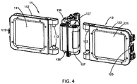
- the lighting device 1 comprises a plurality of lamp bodies. In this embodiment, it comprises two lamp bodies, which are a first lamp body 11 and a second lamp body 12.
- the first lamp body 11 and the second lamp body 12 comprise a first lamp 111 and a second lamp respectively.
- the first lamp 111 and the second lamp 121 provide of lighting when connected to a power source.
- the first lamp body 11 and the second lamp body 12 are oppositely arranged and rotatable relatively to each another.
- the lighting device 1 further comprises a holding device 13.
- the holding device 13 is arranged between the first lamp body 11 and the second lamp body 12.
- the first lamp body 11 and the second lamp body 12 are respectively rotatably connected on the holding device 13.
- the holding device 13 comprises a holding portion 132 and a connecting device 131.
- the connecting device 13 and the first lamp body 11 and the second lamp body 12 are fixedly attached.
- the holding portion 132 is extended from the connecting device 131 so as to form a handle.
- the connecting device 131 has a battery case 133 arranged therewith.
- the direct-current power source is an accumulator.
- the accumulator is arranged in the battery case 133 and electrically connected with the first lamp 111 and the second lamp 121.
- the dismountable direct-current power source facilitates the carrying, replacement, and transportation for the user, so as to further enhance the user-friendliness of the lighting apparatus according to the present invention.
- the handle has antiskid structure arranged thereon, which helps to prevent it from slipping and dropping when the user is holding it.
- the holding device 13 comprises a power switch button 134 and a lighting level button 135.
- the power switch button 134 and the lighting level button 135 are electrically connected with the direct-current power source, so as for people to adjust the light intensity and to turn on/off the first lamp 111 and the second lamp 121. More preferably, the power switch button 134 and the lighting level button 135 are arranged on the connecting device that will not hinder the user to hold the handle, but can facilitate the user to conduct controlling and adjustment to the power switch button 134 and the lighting level button 135 at any time based on the needs.
- person skilled in the art may also respectively arrange a power switch button 134 and a lighting level button 135 for the first lamp 111 and the second lamp 121 based on the needs, so as to respectively control the first lamp 111 and the second lamp 121, such that the user-friendliness of the lighting apparatus according to the present invention can be further enhanced.
- the two sides of the connecting device 131 comprise two first L-form grooves 136 and two second L-form grooves 137 respectively.
- the first lamp body 11 comprises two symmetrical first connecting units 113 affixedly arranged thereon.
- the first lamp body 11 is respectively connected in the first L-form grooves 136 of the connecting device 131 through the first connecting units 113.
- the first lamp body 11 can bring the first connecting units 113 to rotate relatively to the connecting device 131.
- the second lamp body 12 comprises two symmetrical second connecting units 123affixedly arranged thereon.
- the second lamp body 12 is respectively connected in the second L-form grooves 137 of the connecting device 131 through the second connecting units 123.
- the second lamp body 12 can bring the second connecting units 123 to rotate relatively to the connecting device 131.
- the installed first lamp body 11 and second lamp body 12 are on the same plane and both the first lamp body 11 and second lamp body 12 can freely rotate relatively to the connecting device 131 in opposite direction.
- the rotation angle can be, for example, between 0°-180°.
- the first lamp body 11 and the second lamp body 12 can rotate to the positions that they are both on the same plane.
- it can adjust the angle(s) of the first lamp body 11 and/or second lamp body 12 to a sharp angle, right angle or obtuse angle based on the needs, so as to meet the illumination demand of the user.
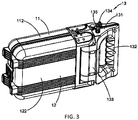
- the first lamp body 11 further comprises a lug 115 thereon, while the second lamp body 12 also comprises a buckle 125 at the corresponding position.
- the first lamp body 11 and the second lamp body 12 are rotated to overlap, it can utilize the lug 115 and the buckle 125 to buckle and lock the first lamp body 11 and the second lamp body 12. Therefore, it can not only provide a portable function, but also protect the first lamp 111 and the second lamp 121 of the first lamp body 11 and the second lamp body 12, which is to kill two birds with one stone. It is understandable that the two lamp bodies 11 and 12 can also be connected and fixed through other dismountable connection mode when they are attached.
- the rotation angle of the first lamp body 11 and the second lamp body 12 may also be adjusted according to actual needs.
- Person skilled in the art only can implement a maximum change of the rotation angle through only conducting a simple adjustment on the structure of the connecting device 131. For instance, it can turn the L-form grooves of the connecting device 131 into a plane that the first lamp body 11 and the second lamp body 12 are respectively rotatably connected with the connecting device 131 on a plane, such that the first lamp body 11 and the second lamp body 12 will not be restricted by the L-form grooves of the lighting device 1 according to the above first embodiment of the present invention during rotation, so as to achieve a larger scale or even 360° rotation.
- Those adopt the same or similar technological means of the present invention and achieve the same or similar technological result are all within the claimed scope of the present invention, while the implementation of the present invention shall not be limited hereby.
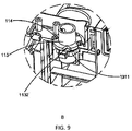
- any of the first connecting units 113 comprises a first spline 1131.
- the first spline sockets 1311 are the sockets of the connecting device 131 that respectively match the first connecting units 113.
- the first splines 1131 are adapted for each first concave portion 13111 in the first spline sockets 1311.
- the first lamp 111 brings the first spline 1131 on each first connecting unit 113 to slide along the first concave portion 13111 in the first spline socket 1311.
- the first spline 1131 on the first connecting unit 113 move for one scale in the first spline socket 1311 to enter the adjacent first concave portion 13111 in the spline socket and be positioned, so as to accomplish a fine adjustment and positioning of the angle of the first lamp 111, which helps the user to conduct adjustment based on the needs or actual conditions.
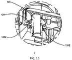
- any of the second connecting units 123 comprises a second spline 1231.
- the second spline sockets 1312 are the sockets of the connecting device 131 that respectively match the second connecting units 123.
- the second splines 1231 are adapted for each second concave portion 13121 in the second spline sockets 1312.
- the second lamp 121 brings the second spline 1231 on each second connecting unit 123 to slide along the second concave portion 13121 in the second spline socket 1312.
- the second spline 1231 on the second connecting unit 123 move for one scale in the second spline socket 1312 to enter the adjacent second concave portion 13121 in the spline socket and be positioned, so as to accomplish the adjustment and positioning of the second lamp 121 for a precise angle, which helps the user to conduct adjustment based on the needs or actual conditions.
- the working principle of the rotation of the first lamp body 11 and the second lamp body 12 relative to the connecting device 131 is simply described as follows.
- the first connecting unit 113 rotates along with the rotation of the first lamp body 11, the first spline 1131 of the first connecting unit 113 will shift in the first spline socket 1311.
- the first spline 1131 of the first connecting unit 113 shifts for one scale in the first spline socket 1311, so as to achieve the rotation and positioning of the first lamp body 11 relative to the connecting device 131.
- the second connecting unit 123 rotates along with the rotation of the second lamp body 12, the second spline 1231 of the second connecting unit 123 will shift in the second spline socket 1312.
- the second spline 1231 of the second connecting unit 123 shifts for one scale in the second spline socket 1312, so as to achieve the rotation and positioning of the second lamp body 12 relative to the connecting device 131.
- the first spline 1131 of the first connecting unit 113, the first spline socket 1311 that is adapted to the first spline 1131, the second spline 1231 of the second connecting unit 123, and the second spline socket 1312 that is adapted to the second spline 1231 are all made of plastic material, so as to tolerate the pressing and distortion occurred when the first spline 1131 is turning in the first spline socket 1311 and when the second spline 1231 is turning in the second spline socket 1312.
- first spline socket 1311 and the second spline socket 1312 can be integrally formed with the connecting device 131 or be separately arranged with the connecting device 131.
- the first lamp body 11 comprises at least a first protruding 114.
- the periphery of the first connecting unit 113 comprises first groove(s) 1132 with the same quantity to the first protruding 114.
- the shapes of first protruding 114 and the first groove 1132 match inside of the first groove 1132.
- the second lamp body 12 comprises at least a second protruding 124.
- the periphery of the second connecting unit 123 comprises second groove(s) 1232 with the same quantity to the second protruding 124.
- the shapes of second protruding 124 and the second groove 1232 match inside of the second groove 1232.
- the first connecting unit 113 and the first lamp body 11 and/or the second connecting unit 123 and the second lamp body 12 can also be fixedly attached or synchronized in motion through other ways. Therefore, those adopt the same or similar technological means to the present invention and achieve the same or similar technological result are all within the claimed scope of the present invention, while the implementation of the present invention shall not be limited hereby.
- first spline 1131 and/or the second spline 1231 may also adjust the dimensions of the first spline 1131 and/or the second spline 1231 based on actual conditions and correspondingly adjust the dimensions of the concave portion(s) of the coordinated first spline socket 1311 and/or the coordinated second spline socket 1312.
- Those adopt the same or similar technological means to the present invention and achieve the same or similar technological result are all within the claimed scope of the present invention, while the implementation of the present invention shall not be limited hereby.
- the first lamp body 11 further comprises a first lampshade 112.
- the first lampshade 112 covers and fastens the first lamp 111, so as to keep the first lamp 111 safe.
- the first lampshade 112 is preferably made of material that perform to moderate light, comprising PC materials and etc., so as to moderate the light emitted from the first lamp 111 in order to protect the user's eyes and prevent the user's eyes from being hurt by exposure to glare, especially at the moment when the first lamp 111 is just turned on.
- the second lamp body 12 further comprises a second lampshade 122.
- the second lampshade 122 covers and fastens the second lamp 121, so as to keep the second lamp 121 safe.
- the second lampshade 122 is preferably made of material that perform to moderate light, comprising PC materials and etc., so as to moderate the light emitted from the second lamp 121 in order to protect the user's eyes and prevent the user's eyes from being hurt by glare dazzling, especially at the moment when the second lamp 121 is just turned on.
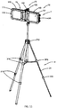
- the lighting apparatus of the present invention further comprises a bracing device 2 for supporting the lighting device 1 and providing a stable position for the lighting device 1.
- the bracing device 2 is a triangular support 21.
- the holding device 13 comprises a rabbet 138 arranged on the lower portion thereof.
- the shape of the top portion 211 of the triangular support 21 and the shape of the rabbet 138 are identical and the outer diameter of the top portion 211 of the triangular support 21 is slightly smaller than the inner diameter of the rabbet 138, such that the rabbet 138 and the top portion 211 of the triangular support 21 are in clearance fit.
- the rabbet 138 and the top portion 211 of the triangular support 21 are both round.
- the implementation of the present invention shall not be limited hereby. Person skilled in the art may arrange the rabbet 138 and the top portion 211 of the triangular support 21 into other shape, comprising lozenge and etc., according to the needs. Therefore, those adopt the same technological means to the present invention and achieve the same or similar technological result are all within the claimed scope of the present invention.
- the triangular support 21 is a multistage adjustable structure.
- the triangular support 21 comprises a first regulator 212 that is able to regulate opening degree and at least a set (a set is three pieces) of second regulators 213 for regulating the height of the triangular support 21. Therefore, the user can employ the first regulator 212 and the second regulators 213 to regulate the height and opening degree of the triangular support 21 according to actual needs, so as to ensure the position of the lighting device 1 meets the illumination demand of the user.
- the lighting apparatus of the present invention can not only be independently carried and utilized with the holding portion 132, but also be utilized in a stationary manner through placing on the triangular support 21. The user may decide the specific usage mode based on actual needs.
- the specific usage mode of the lighting apparatus according to the present invention shall not be limited.
- the tilt angle of the lighting device 1 relative to the triangular support 21 can also be adjusted.
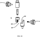
- the triangular support 21 comprises a pair of engaging teeth 22 thereon.
- the rotation direction of the engaging teeth 22 is perpendicular to the rotation directions of the first lamp body 11 and the second lamp body 12.
- the engaging teeth 22 comprises a first cog 221 and a second cog 222.
- the first cog 221 is attached on the lighting device 1 through the first screw 3.
- the second cog 222 is affixedly arranged on the triangular support 21.
- the first cog 221 and the second cog 222 are engaged and fastened through a second screw 4.
- the distance between the first cog 221 and the second cog 222 can be increased, so as to rotate the lighting device 1 to change the engaging position of the first cog 221 and the second cog 222.
- the lighting device 1 When the lighting device 1 is adjusted to an appropriate tilt angle, it can utilize the second screw 4 to engage and fasten the first cog 221 and the second cog 222 again, so as to fix the lighting device 1 on the triangular support 21.
- Person skilled in the art may change each angle of adjustment of the lighting apparatus through changing the interval angle of the first cog 221 and the second cog 222, while the protection scope of the present invention shall not be limited hereby.
- the lighting apparatus according to the present invention is able to not only adjust the precise illumination angle of the first lamp body 11 and the second lamp body 12 from lateral position, but also adjust the precise illumination angle of the first lamp body 11 and the second lamp body 12 from vertical position. Besides, it can accurately position after each of adjustment of the illumination angle, so as to enhance the convenience for the user to utilize the lighting device.
- the lighting device 1 may implement the lighting device 1 according to the present invention through assembling a plurality of the first lamp bodies 11/second lamp bodies 12 and the holding device 13 based on the client's needs or actual conditions.
- the implementation of the present invention shall not be limited hereby. Those adopt the same or similar technological means to the present invention and achieve the same or similar technological result are all within the claimed scope of the present invention.
- the lighting apparatus according to the present invention not only allows accurately axially turning of the angle of the lighting device 1, but also allows changing of the height of the bracing device 2, such that the illumination angle of the lighting apparatus according to the present invention can be adjusted.
- the lighting apparatus according to the present invention also allows adjustment to the illumination direction of the lighting apparatus through adjusting the tilt angle between the lighting device 1 and the bracing device 2. The user can conduct a single or combination adjustment to the lighting apparatus according to the present invention based on the on-site environment or the actual conditions so as to achieve the illumination demand.
- Fig. 14 illustrated an alternative implement of the lighting apparatus according to the above first embodiment of the present invention.
- the bracing device 2' is a lamp post 21'.
- the rabbet 138 on the lower portion of the holding device 13 has the top portion 211' of the lamp post 21' inserted therein, such that the lighting apparatus of the present invention is turned into a pilot lamp standing by the roadside or intersection.
- the lighting apparatus according to the present embodiment can employ the lighting apparatus according to the present embodiment as pilot lamp to provide light or tell/indicate traveling direction for people.
- the two lamp bodies can be structured to provide the same light or different lights, so as to provide pilot signal.
Landscapes
- Engineering & Computer Science (AREA)
- General Engineering & Computer Science (AREA)
- Fastening Of Light Sources Or Lamp Holders (AREA)
- Non-Portable Lighting Devices Or Systems Thereof (AREA)
Applications Claiming Priority (2)
| Application Number | Priority Date | Filing Date | Title |
|---|---|---|---|
| CN201420667544.9U CN204300999U (zh) | 2014-11-10 | 2014-11-10 | 一种工作灯 |
| PCT/CN2015/094156 WO2016074601A2 (fr) | 2014-11-10 | 2015-11-10 | Appareil d'éclairage |
Publications (3)
| Publication Number | Publication Date |
|---|---|
| EP3246624A2 true EP3246624A2 (fr) | 2017-11-22 |
| EP3246624A4 EP3246624A4 (fr) | 2018-07-11 |
| EP3246624B1 EP3246624B1 (fr) | 2020-01-08 |
Family
ID=53106533
Family Applications (1)
| Application Number | Title | Priority Date | Filing Date |
|---|---|---|---|
| EP15859207.1A Active EP3246624B1 (fr) | 2014-11-10 | 2015-11-10 | Appareil d'éclairage |
Country Status (4)
| Country | Link |
|---|---|
| US (1) | US10352537B2 (fr) |
| EP (1) | EP3246624B1 (fr) |
| CN (1) | CN204300999U (fr) |
| WO (1) | WO2016074601A2 (fr) |
Families Citing this family (13)
| Publication number | Priority date | Publication date | Assignee | Title |
|---|---|---|---|---|
| CN204300999U (zh) * | 2014-11-10 | 2015-04-29 | 李金通 | 一种工作灯 |
| CN210266995U (zh) * | 2016-11-23 | 2020-04-07 | 米沃奇电动工具公司 | 区域灯 |
| CN109538987B (zh) * | 2017-09-22 | 2025-08-15 | 宁波福泰电器有限公司 | 便携式灯具及其制造方法 |
| CN110118313B (zh) * | 2018-02-05 | 2025-07-08 | 宁波福泰电器有限公司 | 灯具及其应用 |
| CN110805839A (zh) * | 2018-08-03 | 2020-02-18 | 松下知识产权经营株式会社 | 照明装置 |
| JP7323431B2 (ja) * | 2019-11-07 | 2023-08-08 | 株式会社マキタ | ポータブルライト |
| USD986463S1 (en) * | 2020-08-21 | 2023-05-16 | Keyu Wu | Solar sensor light |
| USD1010905S1 (en) | 2021-08-11 | 2024-01-09 | RAB Lighting Inc. | Adjustable high bay light fixture |
| US11408599B1 (en) * | 2021-09-03 | 2022-08-09 | RAB Lighting Inc. | Articulating linear high bay light fixture |
| US12455065B2 (en) | 2023-08-25 | 2025-10-28 | Milwaukee Electric Tool Corporation | Work light |
| CN220707235U (zh) * | 2023-09-15 | 2024-04-02 | 宁海县瑞海电器有限公司 | 一种可折叠双面发光的泛光灯 |
| USD1101238S1 (en) | 2024-05-01 | 2025-11-04 | Milwaukee Electric Tool Corporation | Work light |
| CN118537905B (zh) * | 2024-05-21 | 2025-03-14 | 江苏思行达信息技术股份有限公司 | 一种用于电网营业厅的人脸识别处理装置及其使用方法 |
Family Cites Families (19)
| Publication number | Priority date | Publication date | Assignee | Title |
|---|---|---|---|---|
| US3585915A (en) * | 1969-05-26 | 1971-06-22 | Atlas Rand Corp | Film metering mechanism for cameras |
| DE3222003A1 (de) * | 1982-06-11 | 1983-12-15 | Hans-Ulrich Prof. Dipl.-Designer 4000 Düsseldorf Bitsch | Bildschirm-arbeitsplatzleuchte |
| US5278735A (en) * | 1993-03-19 | 1994-01-11 | Her Yih S | Distress signal lamp assembly |
| US5424931A (en) * | 1994-05-09 | 1995-06-13 | Wheeler; Todd D. | Mobile illumination device |
| US5890793A (en) * | 1997-05-08 | 1999-04-06 | Stephens; Owen | Portable luminescent lighting system |
| EP1222426B1 (fr) * | 1999-10-12 | 2006-05-31 | Eveready Battery Company, Inc. | Torche electrique a tete pivotante |
| CA2499137C (fr) * | 2004-03-01 | 2012-07-17 | Lee W. Rempel | Lampe avec boitier |
| US20080043457A1 (en) * | 2006-08-21 | 2008-02-21 | Pird, Llc | Illuminating reading material holder and system |
| JP4293314B2 (ja) * | 2007-01-26 | 2009-07-08 | 財団法人山形県産業技術振興機構 | 照明装置 |
| US7954980B2 (en) * | 2009-03-13 | 2011-06-07 | Cooper Technologies Company | Folding rechargeable worklight |
| US8430529B2 (en) * | 2009-03-13 | 2013-04-30 | Cooper Technologies Company | Folding worklight with attachment mechanism |
| US8002438B2 (en) * | 2009-07-27 | 2011-08-23 | Hun-Yuan Ko | Adjustable luminaire |
| CN201611014U (zh) * | 2010-02-04 | 2010-10-20 | 珠海市爱特保实业发展有限公司 | 便携式移动照明系统 |
| US20110205752A1 (en) * | 2010-02-24 | 2011-08-25 | Allen Derek J | Lighting Device |
| AU2011203321B2 (en) * | 2010-07-08 | 2013-12-12 | Signify Holding B.V. | Folding worklight with attachment mechanism |
| CN102401239B (zh) * | 2010-09-14 | 2013-11-13 | 宁波天瑞电器有限公司 | 一种可折叠工作灯 |
| US8201975B1 (en) * | 2011-02-25 | 2012-06-19 | Innovative & Superior Technology Inc. | LED lighting fixture with rotating terminal block |
| WO2014165170A1 (fr) * | 2013-03-12 | 2014-10-09 | International Development LLC | Ensemble lampe de travail repliable |
| CN204300999U (zh) * | 2014-11-10 | 2015-04-29 | 李金通 | 一种工作灯 |
-
2014
- 2014-11-10 CN CN201420667544.9U patent/CN204300999U/zh not_active Expired - Fee Related
-
2015
- 2015-11-10 EP EP15859207.1A patent/EP3246624B1/fr active Active
- 2015-11-10 WO PCT/CN2015/094156 patent/WO2016074601A2/fr not_active Ceased
- 2015-11-10 US US15/525,944 patent/US10352537B2/en not_active Expired - Fee Related
Also Published As
| Publication number | Publication date |
|---|---|
| CN204300999U (zh) | 2015-04-29 |
| WO2016074601A3 (fr) | 2016-07-07 |
| US20180031214A1 (en) | 2018-02-01 |
| EP3246624A4 (fr) | 2018-07-11 |
| WO2016074601A2 (fr) | 2016-05-19 |
| EP3246624B1 (fr) | 2020-01-08 |
| US10352537B2 (en) | 2019-07-16 |
Similar Documents
| Publication | Publication Date | Title |
|---|---|---|
| US10352537B2 (en) | Lighting apparatus | |
| US9243785B2 (en) | Wall mount light assembly | |
| US5788518A (en) | Adjustable connector for track lighting fixture | |
| EP3132185B1 (fr) | Ensemble lumière motorisé | |
| US20170184260A1 (en) | Portable Solar Light That Can Be Secured To Functional Accessories That Can Be Illuminated | |
| US20160025283A1 (en) | Portable lamp | |
| US20160369992A1 (en) | Lamp with protection against shining in an undesired direction | |
| CN205424520U (zh) | 照明设备 | |
| US8985791B1 (en) | Light and base | |
| US9140890B1 (en) | Adjustable magnifying glass mounting system | |
| US9810404B1 (en) | Laser with two levels of image adjustment | |
| KR200477931Y1 (ko) | 탐조등 홀더장치 | |
| EP3732390B1 (fr) | Dispositifs et procédés d'éclairage | |
| KR101522590B1 (ko) | 조명등을 구비한 광고용배너 거치대 | |
| CN214580630U (zh) | 一种可多角调节预防损毁的投光灯 | |
| KR20160091036A (ko) | 경사도를 임의로 조절할 수 있는 깃발 기꽂이 | |
| CN107726264B (zh) | 灯具框架及工作灯 | |
| KR20180006210A (ko) | 회전형 발광장치 | |
| CN219530753U (zh) | 一种可调节的庭院灯 | |
| CN211649993U (zh) | 一种调节稳固型的投光灯 | |
| CN217575439U (zh) | 一种易拆装的自行车灯 | |
| CN214664023U (zh) | 一种多角度可调式混光灯 | |
| CN204922888U (zh) | 一种角度调节装置和一种灯具 | |
| CN203585934U (zh) | 一种工作灯 | |
| CN2929470Y (zh) | 一种照明角度可调节的日光灯支架 |
Legal Events
| Date | Code | Title | Description |
|---|---|---|---|
| STAA | Information on the status of an ep patent application or granted ep patent |
Free format text: STATUS: THE INTERNATIONAL PUBLICATION HAS BEEN MADE |
|
| PUAI | Public reference made under article 153(3) epc to a published international application that has entered the european phase |
Free format text: ORIGINAL CODE: 0009012 |
|
| STAA | Information on the status of an ep patent application or granted ep patent |
Free format text: STATUS: REQUEST FOR EXAMINATION WAS MADE |
|
| 17P | Request for examination filed |
Effective date: 20170609 |
|
| AK | Designated contracting states |
Kind code of ref document: A2 Designated state(s): AL AT BE BG CH CY CZ DE DK EE ES FI FR GB GR HR HU IE IS IT LI LT LU LV MC MK MT NL NO PL PT RO RS SE SI SK SM TR |
|
| AX | Request for extension of the european patent |
Extension state: BA ME |
|
| DAV | Request for validation of the european patent (deleted) | ||
| DAX | Request for extension of the european patent (deleted) | ||
| A4 | Supplementary search report drawn up and despatched |
Effective date: 20180613 |
|
| RIC1 | Information provided on ipc code assigned before grant |
Ipc: F21V 21/14 20060101ALN20180607BHEP Ipc: F21W 131/103 20060101ALN20180607BHEP Ipc: F21V 14/02 20060101ALI20180607BHEP Ipc: F21V 15/01 20060101ALN20180607BHEP Ipc: F21S 6/00 20060101ALI20180607BHEP Ipc: F21S 9/02 20060101ALI20180607BHEP Ipc: F21S 8/08 20060101ALI20180607BHEP Ipc: F21V 21/40 20060101AFI20180607BHEP Ipc: F21V 23/04 20060101ALN20180607BHEP Ipc: F21Y 113/00 20160101ALN20180607BHEP Ipc: F21W 131/10 20060101ALN20180607BHEP |
|
| REG | Reference to a national code |
Ref country code: DE Ref legal event code: R079 Ref document number: 602015045374 Country of ref document: DE Free format text: PREVIOUS MAIN CLASS: F21V0021060000 Ipc: F21V0021400000 |
|
| GRAP | Despatch of communication of intention to grant a patent |
Free format text: ORIGINAL CODE: EPIDOSNIGR1 |
|
| STAA | Information on the status of an ep patent application or granted ep patent |
Free format text: STATUS: GRANT OF PATENT IS INTENDED |
|
| RIC1 | Information provided on ipc code assigned before grant |
Ipc: F21S 8/08 20060101ALI20190612BHEP Ipc: F21Y 113/00 20160101ALN20190612BHEP Ipc: F21S 9/02 20060101ALI20190612BHEP Ipc: F21S 6/00 20060101ALI20190612BHEP Ipc: F21V 21/40 20060101AFI20190612BHEP Ipc: F21V 23/04 20060101ALN20190612BHEP Ipc: F21V 14/02 20060101ALI20190612BHEP Ipc: F21V 21/14 20060101ALN20190612BHEP Ipc: F21W 131/10 20060101ALN20190612BHEP Ipc: F21W 131/103 20060101ALN20190612BHEP Ipc: F21V 15/01 20060101ALN20190612BHEP |
|
| INTG | Intention to grant announced |
Effective date: 20190717 |
|
| GRAS | Grant fee paid |
Free format text: ORIGINAL CODE: EPIDOSNIGR3 |
|
| GRAA | (expected) grant |
Free format text: ORIGINAL CODE: 0009210 |
|
| STAA | Information on the status of an ep patent application or granted ep patent |
Free format text: STATUS: THE PATENT HAS BEEN GRANTED |
|
| AK | Designated contracting states |
Kind code of ref document: B1 Designated state(s): AL AT BE BG CH CY CZ DE DK EE ES FI FR GB GR HR HU IE IS IT LI LT LU LV MC MK MT NL NO PL PT RO RS SE SI SK SM TR |
|
| REG | Reference to a national code |
Ref country code: GB Ref legal event code: FG4D |
|
| REG | Reference to a national code |
Ref country code: CH Ref legal event code: EP |
|
| REG | Reference to a national code |
Ref country code: IE Ref legal event code: FG4D |
|
| REG | Reference to a national code |
Ref country code: DE Ref legal event code: R096 Ref document number: 602015045374 Country of ref document: DE |
|
| REG | Reference to a national code |
Ref country code: AT Ref legal event code: REF Ref document number: 1223162 Country of ref document: AT Kind code of ref document: T Effective date: 20200215 |
|
| REG | Reference to a national code |
Ref country code: NL Ref legal event code: MP Effective date: 20200108 |
|
| REG | Reference to a national code |
Ref country code: LT Ref legal event code: MG4D |
|
| PG25 | Lapsed in a contracting state [announced via postgrant information from national office to epo] |
Ref country code: NL Free format text: LAPSE BECAUSE OF FAILURE TO SUBMIT A TRANSLATION OF THE DESCRIPTION OR TO PAY THE FEE WITHIN THE PRESCRIBED TIME-LIMIT Effective date: 20200108 Ref country code: RS Free format text: LAPSE BECAUSE OF FAILURE TO SUBMIT A TRANSLATION OF THE DESCRIPTION OR TO PAY THE FEE WITHIN THE PRESCRIBED TIME-LIMIT Effective date: 20200108 Ref country code: LT Free format text: LAPSE BECAUSE OF FAILURE TO SUBMIT A TRANSLATION OF THE DESCRIPTION OR TO PAY THE FEE WITHIN THE PRESCRIBED TIME-LIMIT Effective date: 20200108 Ref country code: PT Free format text: LAPSE BECAUSE OF FAILURE TO SUBMIT A TRANSLATION OF THE DESCRIPTION OR TO PAY THE FEE WITHIN THE PRESCRIBED TIME-LIMIT Effective date: 20200531 Ref country code: NO Free format text: LAPSE BECAUSE OF FAILURE TO SUBMIT A TRANSLATION OF THE DESCRIPTION OR TO PAY THE FEE WITHIN THE PRESCRIBED TIME-LIMIT Effective date: 20200408 Ref country code: FI Free format text: LAPSE BECAUSE OF FAILURE TO SUBMIT A TRANSLATION OF THE DESCRIPTION OR TO PAY THE FEE WITHIN THE PRESCRIBED TIME-LIMIT Effective date: 20200108 |
|
| PG25 | Lapsed in a contracting state [announced via postgrant information from national office to epo] |
Ref country code: SE Free format text: LAPSE BECAUSE OF FAILURE TO SUBMIT A TRANSLATION OF THE DESCRIPTION OR TO PAY THE FEE WITHIN THE PRESCRIBED TIME-LIMIT Effective date: 20200108 Ref country code: LV Free format text: LAPSE BECAUSE OF FAILURE TO SUBMIT A TRANSLATION OF THE DESCRIPTION OR TO PAY THE FEE WITHIN THE PRESCRIBED TIME-LIMIT Effective date: 20200108 Ref country code: HR Free format text: LAPSE BECAUSE OF FAILURE TO SUBMIT A TRANSLATION OF THE DESCRIPTION OR TO PAY THE FEE WITHIN THE PRESCRIBED TIME-LIMIT Effective date: 20200108 Ref country code: GR Free format text: LAPSE BECAUSE OF FAILURE TO SUBMIT A TRANSLATION OF THE DESCRIPTION OR TO PAY THE FEE WITHIN THE PRESCRIBED TIME-LIMIT Effective date: 20200409 Ref country code: IS Free format text: LAPSE BECAUSE OF FAILURE TO SUBMIT A TRANSLATION OF THE DESCRIPTION OR TO PAY THE FEE WITHIN THE PRESCRIBED TIME-LIMIT Effective date: 20200508 Ref country code: BG Free format text: LAPSE BECAUSE OF FAILURE TO SUBMIT A TRANSLATION OF THE DESCRIPTION OR TO PAY THE FEE WITHIN THE PRESCRIBED TIME-LIMIT Effective date: 20200408 |
|
| REG | Reference to a national code |
Ref country code: DE Ref legal event code: R097 Ref document number: 602015045374 Country of ref document: DE |
|
| PG25 | Lapsed in a contracting state [announced via postgrant information from national office to epo] |
Ref country code: SK Free format text: LAPSE BECAUSE OF FAILURE TO SUBMIT A TRANSLATION OF THE DESCRIPTION OR TO PAY THE FEE WITHIN THE PRESCRIBED TIME-LIMIT Effective date: 20200108 Ref country code: RO Free format text: LAPSE BECAUSE OF FAILURE TO SUBMIT A TRANSLATION OF THE DESCRIPTION OR TO PAY THE FEE WITHIN THE PRESCRIBED TIME-LIMIT Effective date: 20200108 Ref country code: CZ Free format text: LAPSE BECAUSE OF FAILURE TO SUBMIT A TRANSLATION OF THE DESCRIPTION OR TO PAY THE FEE WITHIN THE PRESCRIBED TIME-LIMIT Effective date: 20200108 Ref country code: ES Free format text: LAPSE BECAUSE OF FAILURE TO SUBMIT A TRANSLATION OF THE DESCRIPTION OR TO PAY THE FEE WITHIN THE PRESCRIBED TIME-LIMIT Effective date: 20200108 Ref country code: EE Free format text: LAPSE BECAUSE OF FAILURE TO SUBMIT A TRANSLATION OF THE DESCRIPTION OR TO PAY THE FEE WITHIN THE PRESCRIBED TIME-LIMIT Effective date: 20200108 Ref country code: DK Free format text: LAPSE BECAUSE OF FAILURE TO SUBMIT A TRANSLATION OF THE DESCRIPTION OR TO PAY THE FEE WITHIN THE PRESCRIBED TIME-LIMIT Effective date: 20200108 Ref country code: SM Free format text: LAPSE BECAUSE OF FAILURE TO SUBMIT A TRANSLATION OF THE DESCRIPTION OR TO PAY THE FEE WITHIN THE PRESCRIBED TIME-LIMIT Effective date: 20200108 |
|
| PLBE | No opposition filed within time limit |
Free format text: ORIGINAL CODE: 0009261 |
|
| STAA | Information on the status of an ep patent application or granted ep patent |
Free format text: STATUS: NO OPPOSITION FILED WITHIN TIME LIMIT |
|
| REG | Reference to a national code |
Ref country code: AT Ref legal event code: MK05 Ref document number: 1223162 Country of ref document: AT Kind code of ref document: T Effective date: 20200108 |
|
| 26N | No opposition filed |
Effective date: 20201009 |
|
| PG25 | Lapsed in a contracting state [announced via postgrant information from national office to epo] |
Ref country code: IT Free format text: LAPSE BECAUSE OF FAILURE TO SUBMIT A TRANSLATION OF THE DESCRIPTION OR TO PAY THE FEE WITHIN THE PRESCRIBED TIME-LIMIT Effective date: 20200108 Ref country code: AT Free format text: LAPSE BECAUSE OF FAILURE TO SUBMIT A TRANSLATION OF THE DESCRIPTION OR TO PAY THE FEE WITHIN THE PRESCRIBED TIME-LIMIT Effective date: 20200108 |
|
| PGFP | Annual fee paid to national office [announced via postgrant information from national office to epo] |
Ref country code: GB Payment date: 20201222 Year of fee payment: 6 Ref country code: FR Payment date: 20201215 Year of fee payment: 6 |
|
| PG25 | Lapsed in a contracting state [announced via postgrant information from national office to epo] |
Ref country code: SI Free format text: LAPSE BECAUSE OF FAILURE TO SUBMIT A TRANSLATION OF THE DESCRIPTION OR TO PAY THE FEE WITHIN THE PRESCRIBED TIME-LIMIT Effective date: 20200108 Ref country code: PL Free format text: LAPSE BECAUSE OF FAILURE TO SUBMIT A TRANSLATION OF THE DESCRIPTION OR TO PAY THE FEE WITHIN THE PRESCRIBED TIME-LIMIT Effective date: 20200108 |
|
| PGFP | Annual fee paid to national office [announced via postgrant information from national office to epo] |
Ref country code: DE Payment date: 20201217 Year of fee payment: 6 |
|
| PG25 | Lapsed in a contracting state [announced via postgrant information from national office to epo] |
Ref country code: MC Free format text: LAPSE BECAUSE OF FAILURE TO SUBMIT A TRANSLATION OF THE DESCRIPTION OR TO PAY THE FEE WITHIN THE PRESCRIBED TIME-LIMIT Effective date: 20200108 |
|
| REG | Reference to a national code |
Ref country code: CH Ref legal event code: PL |
|
| PG25 | Lapsed in a contracting state [announced via postgrant information from national office to epo] |
Ref country code: LU Free format text: LAPSE BECAUSE OF NON-PAYMENT OF DUE FEES Effective date: 20201110 |
|
| REG | Reference to a national code |
Ref country code: BE Ref legal event code: MM Effective date: 20201130 |
|
| PG25 | Lapsed in a contracting state [announced via postgrant information from national office to epo] |
Ref country code: CH Free format text: LAPSE BECAUSE OF NON-PAYMENT OF DUE FEES Effective date: 20201130 Ref country code: LI Free format text: LAPSE BECAUSE OF NON-PAYMENT OF DUE FEES Effective date: 20201130 |
|
| PG25 | Lapsed in a contracting state [announced via postgrant information from national office to epo] |
Ref country code: IE Free format text: LAPSE BECAUSE OF NON-PAYMENT OF DUE FEES Effective date: 20201110 |
|
| PG25 | Lapsed in a contracting state [announced via postgrant information from national office to epo] |
Ref country code: TR Free format text: LAPSE BECAUSE OF FAILURE TO SUBMIT A TRANSLATION OF THE DESCRIPTION OR TO PAY THE FEE WITHIN THE PRESCRIBED TIME-LIMIT Effective date: 20200108 Ref country code: MT Free format text: LAPSE BECAUSE OF FAILURE TO SUBMIT A TRANSLATION OF THE DESCRIPTION OR TO PAY THE FEE WITHIN THE PRESCRIBED TIME-LIMIT Effective date: 20200108 Ref country code: CY Free format text: LAPSE BECAUSE OF FAILURE TO SUBMIT A TRANSLATION OF THE DESCRIPTION OR TO PAY THE FEE WITHIN THE PRESCRIBED TIME-LIMIT Effective date: 20200108 |
|
| REG | Reference to a national code |
Ref country code: DE Ref legal event code: R119 Ref document number: 602015045374 Country of ref document: DE |
|
| PG25 | Lapsed in a contracting state [announced via postgrant information from national office to epo] |
Ref country code: MK Free format text: LAPSE BECAUSE OF FAILURE TO SUBMIT A TRANSLATION OF THE DESCRIPTION OR TO PAY THE FEE WITHIN THE PRESCRIBED TIME-LIMIT Effective date: 20200108 Ref country code: AL Free format text: LAPSE BECAUSE OF FAILURE TO SUBMIT A TRANSLATION OF THE DESCRIPTION OR TO PAY THE FEE WITHIN THE PRESCRIBED TIME-LIMIT Effective date: 20200108 |
|
| GBPC | Gb: european patent ceased through non-payment of renewal fee |
Effective date: 20211110 |
|
| PG25 | Lapsed in a contracting state [announced via postgrant information from national office to epo] |
Ref country code: BE Free format text: LAPSE BECAUSE OF NON-PAYMENT OF DUE FEES Effective date: 20201130 |
|
| PG25 | Lapsed in a contracting state [announced via postgrant information from national office to epo] |
Ref country code: GB Free format text: LAPSE BECAUSE OF NON-PAYMENT OF DUE FEES Effective date: 20211110 Ref country code: DE Free format text: LAPSE BECAUSE OF NON-PAYMENT OF DUE FEES Effective date: 20220601 |
|
| PG25 | Lapsed in a contracting state [announced via postgrant information from national office to epo] |
Ref country code: FR Free format text: LAPSE BECAUSE OF NON-PAYMENT OF DUE FEES Effective date: 20211130 |