EP3246628B1 - Petite turbomachine dotée d'un système d'allumage - Google Patents
Petite turbomachine dotée d'un système d'allumage Download PDFInfo
- Publication number
- EP3246628B1 EP3246628B1 EP17171711.9A EP17171711A EP3246628B1 EP 3246628 B1 EP3246628 B1 EP 3246628B1 EP 17171711 A EP17171711 A EP 17171711A EP 3246628 B1 EP3246628 B1 EP 3246628B1
- Authority
- EP
- European Patent Office
- Prior art keywords
- fuel
- combustion chamber
- starting
- small turbine
- turbine engine
- Prior art date
- Legal status (The legal status is an assumption and is not a legal conclusion. Google has not performed a legal analysis and makes no representation as to the accuracy of the status listed.)
- Active
Links
Images

Classifications
-
- F—MECHANICAL ENGINEERING; LIGHTING; HEATING; WEAPONS; BLASTING
- F23—COMBUSTION APPARATUS; COMBUSTION PROCESSES
- F23K—FEEDING FUEL TO COMBUSTION APPARATUS
- F23K5/00—Feeding or distributing other fuel to combustion apparatus
- F23K5/02—Liquid fuel
- F23K5/04—Feeding or distributing systems using pumps
-
- F—MECHANICAL ENGINEERING; LIGHTING; HEATING; WEAPONS; BLASTING
- F02—COMBUSTION ENGINES; HOT-GAS OR COMBUSTION-PRODUCT ENGINE PLANTS
- F02C—GAS-TURBINE PLANTS; AIR INTAKES FOR JET-PROPULSION PLANTS; CONTROLLING FUEL SUPPLY IN AIR-BREATHING JET-PROPULSION PLANTS
- F02C7/00—Features, components parts, details or accessories, not provided for in, or of interest apart form groups F02C1/00 - F02C6/00; Air intakes for jet-propulsion plants
- F02C7/22—Fuel supply systems
- F02C7/228—Dividing fuel between various burners
-
- F—MECHANICAL ENGINEERING; LIGHTING; HEATING; WEAPONS; BLASTING
- F02—COMBUSTION ENGINES; HOT-GAS OR COMBUSTION-PRODUCT ENGINE PLANTS
- F02C—GAS-TURBINE PLANTS; AIR INTAKES FOR JET-PROPULSION PLANTS; CONTROLLING FUEL SUPPLY IN AIR-BREATHING JET-PROPULSION PLANTS
- F02C7/00—Features, components parts, details or accessories, not provided for in, or of interest apart form groups F02C1/00 - F02C6/00; Air intakes for jet-propulsion plants
- F02C7/22—Fuel supply systems
- F02C7/236—Fuel delivery systems comprising two or more pumps
-
- F—MECHANICAL ENGINEERING; LIGHTING; HEATING; WEAPONS; BLASTING
- F02—COMBUSTION ENGINES; HOT-GAS OR COMBUSTION-PRODUCT ENGINE PLANTS
- F02C—GAS-TURBINE PLANTS; AIR INTAKES FOR JET-PROPULSION PLANTS; CONTROLLING FUEL SUPPLY IN AIR-BREATHING JET-PROPULSION PLANTS
- F02C7/00—Features, components parts, details or accessories, not provided for in, or of interest apart form groups F02C1/00 - F02C6/00; Air intakes for jet-propulsion plants
- F02C7/26—Starting; Ignition
-
- F—MECHANICAL ENGINEERING; LIGHTING; HEATING; WEAPONS; BLASTING
- F02—COMBUSTION ENGINES; HOT-GAS OR COMBUSTION-PRODUCT ENGINE PLANTS
- F02C—GAS-TURBINE PLANTS; AIR INTAKES FOR JET-PROPULSION PLANTS; CONTROLLING FUEL SUPPLY IN AIR-BREATHING JET-PROPULSION PLANTS
- F02C7/00—Features, components parts, details or accessories, not provided for in, or of interest apart form groups F02C1/00 - F02C6/00; Air intakes for jet-propulsion plants
- F02C7/26—Starting; Ignition
- F02C7/264—Ignition
- F02C7/266—Electric
-
- F—MECHANICAL ENGINEERING; LIGHTING; HEATING; WEAPONS; BLASTING
- F23—COMBUSTION APPARATUS; COMBUSTION PROCESSES
- F23R—GENERATING COMBUSTION PRODUCTS OF HIGH PRESSURE OR HIGH VELOCITY, e.g. GAS-TURBINE COMBUSTION CHAMBERS
- F23R3/00—Continuous combustion chambers using liquid or gaseous fuel
- F23R3/02—Continuous combustion chambers using liquid or gaseous fuel characterised by the air-flow or gas-flow configuration
- F23R3/04—Air inlet arrangements
- F23R3/06—Arrangement of apertures along the flame tube
-
- F—MECHANICAL ENGINEERING; LIGHTING; HEATING; WEAPONS; BLASTING
- F23—COMBUSTION APPARATUS; COMBUSTION PROCESSES
- F23R—GENERATING COMBUSTION PRODUCTS OF HIGH PRESSURE OR HIGH VELOCITY, e.g. GAS-TURBINE COMBUSTION CHAMBERS
- F23R3/00—Continuous combustion chambers using liquid or gaseous fuel
- F23R3/28—Continuous combustion chambers using liquid or gaseous fuel characterised by the fuel supply
-
- F—MECHANICAL ENGINEERING; LIGHTING; HEATING; WEAPONS; BLASTING
- F23—COMBUSTION APPARATUS; COMBUSTION PROCESSES
- F23R—GENERATING COMBUSTION PRODUCTS OF HIGH PRESSURE OR HIGH VELOCITY, e.g. GAS-TURBINE COMBUSTION CHAMBERS
- F23R3/00—Continuous combustion chambers using liquid or gaseous fuel
- F23R3/28—Continuous combustion chambers using liquid or gaseous fuel characterised by the fuel supply
- F23R3/30—Continuous combustion chambers using liquid or gaseous fuel characterised by the fuel supply comprising fuel prevapourising devices
- F23R3/32—Continuous combustion chambers using liquid or gaseous fuel characterised by the fuel supply comprising fuel prevapourising devices being tubular
-
- F—MECHANICAL ENGINEERING; LIGHTING; HEATING; WEAPONS; BLASTING
- F23—COMBUSTION APPARATUS; COMBUSTION PROCESSES
- F23R—GENERATING COMBUSTION PRODUCTS OF HIGH PRESSURE OR HIGH VELOCITY, e.g. GAS-TURBINE COMBUSTION CHAMBERS
- F23R3/00—Continuous combustion chambers using liquid or gaseous fuel
- F23R3/28—Continuous combustion chambers using liquid or gaseous fuel characterised by the fuel supply
- F23R3/34—Feeding into different combustion zones
- F23R3/343—Pilot flames, i.e. fuel nozzles or injectors using only a very small proportion of the total fuel to insure continuous combustion
-
- F—MECHANICAL ENGINEERING; LIGHTING; HEATING; WEAPONS; BLASTING
- F23—COMBUSTION APPARATUS; COMBUSTION PROCESSES
- F23N—REGULATING OR CONTROLLING COMBUSTION
- F23N2227/00—Ignition or checking
- F23N2227/36—Spark ignition, e.g. by means of a high voltage
-
- F—MECHANICAL ENGINEERING; LIGHTING; HEATING; WEAPONS; BLASTING
- F23—COMBUSTION APPARATUS; COMBUSTION PROCESSES
- F23N—REGULATING OR CONTROLLING COMBUSTION
- F23N2227/00—Ignition or checking
- F23N2227/38—Electrical resistance ignition
Definitions
- the invention relates to a small turbine engine with an ignition system comprising a combustion chamber connectable to a fuel-air mixture supply, the combustion chamber being provided with an ignition system with a glow plug.
- the pre-heating of the space of the combustion chamber is used to ignite the main fuel by means of gas fuel, fed by a separate manifold from a pressure vessel through a starter valve.
- gas fuel fed by a separate manifold from a pressure vessel through a starter valve.
- the main fuel is fed into the evaporating tubes inside the combustion chamber, which continues burning by itself and the feed of the starting gas fuel is interrupted.
- the second option is direct ignition of the main fuel by means of a ceramic glow plug, in which the main fuel is fed to the plug by a branch line from the main fuel manifold through a starter valve.
- the aim of the invention is to eliminate or at least minimize the drawbacks of the background art, especially to reduce the time required to reach the operating mode of the engine, improve or allow starting at low temperatures and temperatures below the freezing point and at higher flight speeds.
- Gas turbines with ignition systems are known in the prior art from US2015/0369489 , US3611717 , US3668869 , US2008/0209910 and US2667742 .
- the aim of the invention is achieved by a small turbine engine according to claim 1.
- the invention significantly extends the possibilities of starting small turbine engines in terms of flight velocity, low or minus ambient temperatures and altitudes and enables to start the engines in any position relative to the ground.
- a high-angle spray starting bypass nozzle ensures combustion of the fuel-air mixture in a large part of the combustion chamber in both the longitudinal and circumferential directions and thus allows the rapid and effective start of the engine into the operating mode, for example, in the case of the engine with evaporating tubes, it ensures rapid heating of the evaporating tubes before opening the main fuel supply.
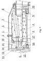
- Fig. 1 shows a cross-sectional view of a small turbine engine with an ignition system according to the invention
- Fig. 2 shows an arrangement of the fuel system of the small turbine engine according to the invention.
- the invention will be described with reference to an exemplary embodiment of a small turbine engine with an annular combustion chamber 1.
- the combustion chamber 1 comprises an outer shell 5, an inner shell 4 and a front 6.
- fuel evaporating tubes 7 are arranged along the circumference of the combustion chamber 1.
- the fuel evaporating tubes 7 are mounted with their rear ends, in the left-to-right direction, in an annular carrier 8.
- the outlet of the exhaust gas from the combustion chamber 1 is joined by a turbine distribution wheel 9 and a turbine action wheel 10, which constitute the outlet portion of the engine and which are rotatably mounted in a known manner on the structure of the engine.
- the main fuel is fed into the combustion chamber 1 from a manifold 11 through capillary tubes 12 to the evaporating tubes 7, through which the air is supplied to the inner space of the combustion chamber 1 in a known manner from an axial diffuser 14.
- the air flows into the combustion chamber 1 also through the holes in the walls of the combustion chamber 1.
- An air compressor 13 is rotatably mounted at the inlet to the engine, whereby the air, having passed through the compressor 13, flows into the space of the engine with the combustion chamber 1 through the axial diffuser 14.
- the compressor 13 is coupled to an unillustrated start-up device, e.g. an electromotor.
- the combustion chamber 1 is provided with at least one bypass nozzle 2 and spaced therefrom by at least one glow plug 3. Both the bypass nozzle 2 and the glow plug 3 are preferably situated in the area of the inner space of the combustion chamber 1, into which lead the evaporating tubes 7. In the illustrated embodiment, both the bypass nozzle 2 and the glow plug 3 are situated at the front 6 of the combustion chamber 1, or the bypass nozzle 2 is arranged in the inclined surface of the front 6 of the combustion chamber 1 or in another suitable part of the combustion chamber 1 at the entrance of the evaporating tubes 7 to the combustion chamber 1.
- the starter bypass nozzle 2 is with its inlet connected to the fuel supply pipe line 15, whereby it is connected to the suction of the starting pump 24 with its bypass outlet by means of a bypass pipe 16.
- the starter bypass nozzle 2 is arranged in such a manner that most of the amount of the fuel delivered by means of the fuel supply pipe line 15 returns through the bypass pipe 16 to the suction of the starting pump 24.
- a smaller portion of the fuel is by means of the starter bypass nozzle 2, which has a fuel spray angle in the range from 60° to 110°, ideally 90°, injected into the combustion chamber 1, where fuel properly sprayed is formed.
- the amount of the injected fuel is determined by the setting of the main fuel pump 21, which dispenses the fuel into the engine and hence also into the starting fuel pump 24.
- the starter bypass nozzle 2 has a large injection opening as well as a large bypass opening, so that there is no risk of blockage, and low fuel pressure is sufficient for the nozzle 2 to function.
- the ceramic glow plug 3 which ignites the fuel-air mixture, is mounted in the body of the combustion chamber 1 in the illustrated example of embodiment by means of a cooling housing 17 with an opening 18 situated in front of the combustion chamber, so that the air from the axial diffuser 14 flows through this opening 18 to provide the cooling of the glow plug 3.
- the ceramic glow plug 3 is located in such a manner that the droplets of the fuel from the starting bypass nozzle 2 fall on it.
- a fuel tank 25 is assigned to the engine, being connected to the main fuel pump 21, from which the fuel is further fed through a fuel filter 26, behind which the fuel manifold is divided into branches - a starting fuel branch connected through a starting solenoid valve 22 and an operating fuel branch connected through an operating solenoid valve 23.
- the fuel is fed to the inlet of the starting pump 24, whose outlet is connected by means of the fuel supply pipeline 15 to the inlet of the starting bypass nozzle 2.
- the outlet of the bypass nozzle is connected 2 by means of the bypass pipe 16 to the starting fuel branch between the starting solenoid valve 22 and the starting pump 24, i.e., it is connected to the suction of the starting pump 24.
- the operating fuel branch leads beyond the operating solenoid valve 23 to the manifold 11 and further on to the capillary tubes 12 and to the evaporating tubes 7 in the combustion chamber 1.
- the fuel is delivered by this manifold from the main pump 21 to the evaporating tubes 7 and into the combustion chamber 1.
- a small turbine engine with an ignition system is operated in such a manner that after the start-up of the engine at first the compressor 13 starts to rotate, thereby forcing the air into the engine.
- the fuel is injected with the starter bypass nozzle 2 into the front of the combustion chamber 1 , where it is mixed with the air passing through the openings in the walls of the combustion chamber 1 and through the evaporating tubes 7.
- the mixture is ignited with the ceramic glow plug 3, whereby more fuel is injected with the starter bypass nozzle 2.
- the starting solenoid valve 22 is closed and the starting pump 24 , the glow plug 3 and the starter bypass nozzle 2 are disconnected, and the fuel is henceforth fed to the engine only by means of the operating solenoid valve 23 through the manifold 11 and the capillary tubes 12 to the evaporating tubes 7.
- the invention is not limited only to turbine engines with evaporating tubes, but it can be also used in other turbine engines.
Landscapes
- Engineering & Computer Science (AREA)
- Chemical & Material Sciences (AREA)
- Combustion & Propulsion (AREA)
- Mechanical Engineering (AREA)
- General Engineering & Computer Science (AREA)
- Dowels (AREA)
- Combustion Methods Of Internal-Combustion Engines (AREA)
- Fuel-Injection Apparatus (AREA)
- Supercharger (AREA)
Claims (5)
- Petit turbomoteur avec système d'allumage comprenant une chambre de combustion (1) qui peut être connectée à l'arrivée du carburant et de l'air, tandis que la chambre de combustion (1) est munie d'un système d'allumage avec une bougie de préchauffage (3), où la chambre de combustion (1) est munie d'au moins une buse de dérivation de démarrage (2) avec angle d'arrosage de carburant entre 60° et 110°, et d'une pompe de démarrage (24), tandis que la buse de dérivation de démarrage (2) est connectée, à l'aide de la pompe de démarrage (24), à l'arrivée du carburant dans le moteur, où l'arrivée du carburant dans le moteur comprend la pompe principale (21), derrière laquelle le conduit de carburant est divisé en deux branches - branche carburant de démarrage avec électrovanne (22) et branche de service avec électrovanne de (23), tandis que derrière l'électrovanne de démarrage (22) le carburant est conduit dans l'entrée de la pompe de démarrage (24) dont la sortie est connectée, par le conduit d'arrivée du carburant (15), à l'entrée de la buse de dérivation de démarrage (2), dont la sortie est connectée, à l'aide de conduit de dérivation (16), à la branche carburant de démarrage entre l'électrovanne de démarrage (22) et la pompe de démarrage (24).
- Petit turbomoteur selon la revendication 1, caractérisé en ce que la chambre de combustion est une chambre de combustion annulaire (1) avec enveloppe, tandis que la buse de dérivation de démarrage (2) et la bougie de préchauffage (3) sont fixées à l'enveloppe de la chambre de combustion annulaire (1).
- Petit turbomoteur selon la revendication 1 ou 2, caractérisé en ce que la buse de dérivation de démarrage (2) se situe à l'avant (6) de la chambre de combustion (1).
- Petit turbomoteur selon la revendication 1, caractérisé en ce que la branche de carburant de service derrière l'électrovanne de service (23) est guidée dans la distribution (11) du carburant et ensuite dans les tubes capillaires (12) et les tuyaux d'évaporation (7) dans la chambre de combustion (1).
- Petit turbomoteur selon la revendication 1 ou 4, caractérisé en ce que la pompe principale (21) est adaptée pour déterminer la quantité du carburant injecté lors du démarrage du moteur et la pompe de démarrage (24) est adaptée pour déterminer la quantité du carburant qui arrive dans l'entrée de la buse de dérivation de démarrage (2).
Applications Claiming Priority (1)
| Application Number | Priority Date | Filing Date | Title |
|---|---|---|---|
| CZ2016-296A CZ308533B6 (cs) | 2016-05-19 | 2016-05-19 | Malý turbínový motor se zapalovacím systémem |
Publications (2)
| Publication Number | Publication Date |
|---|---|
| EP3246628A1 EP3246628A1 (fr) | 2017-11-22 |
| EP3246628B1 true EP3246628B1 (fr) | 2021-03-10 |
Family
ID=59091309
Family Applications (1)
| Application Number | Title | Priority Date | Filing Date |
|---|---|---|---|
| EP17171711.9A Active EP3246628B1 (fr) | 2016-05-19 | 2017-05-18 | Petite turbomachine dotée d'un système d'allumage |
Country Status (2)
| Country | Link |
|---|---|
| EP (1) | EP3246628B1 (fr) |
| CZ (1) | CZ308533B6 (fr) |
Cited By (1)
| Publication number | Priority date | Publication date | Assignee | Title |
|---|---|---|---|---|
| US20230272749A1 (en) * | 2022-02-28 | 2023-08-31 | General Electric Company | Fuel system having a coke filtration system |
Families Citing this family (4)
| Publication number | Priority date | Publication date | Assignee | Title |
|---|---|---|---|---|
| CN111520752A (zh) * | 2020-03-17 | 2020-08-11 | 西北工业大学 | 一种微型燃烧室蒸发管结构 |
| CN113864064B (zh) * | 2021-09-28 | 2024-11-01 | 北京永旭腾风新能源动力科技发展有限公司 | 具有双燃料系统的燃料供给系统及微型燃气轮机 |
| CN114109614B (zh) * | 2021-11-05 | 2024-06-07 | 苏州凯德航空科技有限公司 | 一种微型涡轮喷气发动机快速点火系统及其点火方法 |
| CN114263535B (zh) * | 2021-12-14 | 2023-11-14 | 西安现代控制技术研究所 | 一种有效提高微型涡喷发动机点火可靠性的方法 |
Citations (2)
| Publication number | Priority date | Publication date | Assignee | Title |
|---|---|---|---|---|
| US2818704A (en) * | 1952-10-30 | 1958-01-07 | Gen Motors Corp | Turbine engine starting system |
| US20080209910A1 (en) * | 2007-03-02 | 2008-09-04 | Turbomeca | Method of starting a gas turbine helicopter engine, a fuel feed circuit for such an engine, and an engine having such a circuit |
Family Cites Families (9)
| Publication number | Priority date | Publication date | Assignee | Title |
|---|---|---|---|---|
| US2667742A (en) * | 1947-02-24 | 1954-02-02 | Bendix Aviat Corp | Starting system for gas turbine engines |
| GB651706A (en) * | 1948-12-29 | 1951-04-04 | Rolls Royce | Improvements relating to gas turbine engine fuel systems |
| BE546730A (fr) * | 1955-04-05 | |||
| US2941363A (en) * | 1955-04-11 | 1960-06-21 | Bendix Aviat Corp | Dual baffled igniter for combustion chamber |
| FR2040938A5 (fr) * | 1969-04-24 | 1971-01-22 | Snecma | |
| US4121419A (en) * | 1977-01-26 | 1978-10-24 | Kuznetsov Vladimir Grigorievic | Start flame igniter of the combustion chamber of a gas-turbine engine |
| DE2722449C2 (de) * | 1977-05-18 | 1982-08-05 | MTU Motoren- und Turbinen-Union München GmbH, 8000 München | Zündeinrichtung einer Brennkammer für Gasturbinentriebwerke, insbesondere für Gasturbinenstrahltriebwerke von Flugzeugen |
| EP1965560A1 (fr) * | 2007-03-01 | 2008-09-03 | Advanced Digital Broadcast S.A. | Procédé et système pour la gestion de l'accès sécurité au contenu de réseau |
| FR3001497B1 (fr) * | 2013-01-29 | 2016-05-13 | Turbomeca | Ensemble de combustion de turbomachine comprenant un circuit d alimentation de carburant ameliore |
-
2016
- 2016-05-19 CZ CZ2016-296A patent/CZ308533B6/cs unknown
-
2017
- 2017-05-18 EP EP17171711.9A patent/EP3246628B1/fr active Active
Patent Citations (2)
| Publication number | Priority date | Publication date | Assignee | Title |
|---|---|---|---|---|
| US2818704A (en) * | 1952-10-30 | 1958-01-07 | Gen Motors Corp | Turbine engine starting system |
| US20080209910A1 (en) * | 2007-03-02 | 2008-09-04 | Turbomeca | Method of starting a gas turbine helicopter engine, a fuel feed circuit for such an engine, and an engine having such a circuit |
Non-Patent Citations (1)
| Title |
|---|
| "Gas turbine combustion : alternative fuels and emissions", 26 April 2010, CRC PRESS, Boca Raton, Fla. [u.a.], ISBN: 978-1-4200-8604-1, article ARTHUR LEFEBVRE: "Gas Turbine Combustion", XP055646223 * |
Cited By (2)
| Publication number | Priority date | Publication date | Assignee | Title |
|---|---|---|---|---|
| US20230272749A1 (en) * | 2022-02-28 | 2023-08-31 | General Electric Company | Fuel system having a coke filtration system |
| US11994071B2 (en) * | 2022-02-28 | 2024-05-28 | General Electric Company | Fuel system having a coke filtration system |
Also Published As
| Publication number | Publication date |
|---|---|
| CZ308533B6 (cs) | 2020-10-29 |
| EP3246628A1 (fr) | 2017-11-22 |
| CZ2016296A3 (cs) | 2017-11-29 |
Similar Documents
| Publication | Publication Date | Title |
|---|---|---|
| EP3246628B1 (fr) | Petite turbomachine dotée d'un système d'allumage | |
| JP6170562B2 (ja) | タービンエンジンの燃焼室のための2つの回路の噴射器 | |
| EP4019838B1 (fr) | Système d'allumeur torche pour une chambre de combustion de turbine à gaz et procédé d'utilisation associé | |
| US2540642A (en) | Multiple combustion chamber torch igniter and auxiliary fuel spray device arrangement for initiating combustion | |
| CN105102789B (zh) | 包括改进的燃料供给回路的涡轮机燃烧组件 | |
| US8006500B1 (en) | Swirl combustor with counter swirl fuel slinger | |
| EP4113009B1 (fr) | Torche d'allumage pour un moteur de turbine à gaz | |
| EP4019839B1 (fr) | Système d'allumeur de torche avec démarrage assisté au gaz | |
| US6941760B1 (en) | Start system for expendable gas turbine engine | |
| CN109441643A (zh) | 微小型涡喷发动机和燃气轮机燃烧室点火装置 | |
| US5665272A (en) | Multifuel combustion engine and use in generating obscurant smoke | |
| US3092964A (en) | Method of relighting in combustion chambers | |
| US3124933A (en) | Leroy stram | |
| KR101268393B1 (ko) | 하이브리드 추진기관 | |
| KR101037456B1 (ko) | 가스터빈 엔진용 연소기의 점화장치 | |
| US11067036B2 (en) | Combustor and jet engine having the same | |
| CN102985757B (zh) | 涡轮发动机燃烧室的点火过程 | |
| US6370861B1 (en) | Solid fuel afterburner and method of using the same to improve thrust and starting capabilities of a turbojet engine | |
| US5115637A (en) | External cartridge gas combustor ignitor | |
| JP2015183683A5 (fr) | ||
| US2968152A (en) | Air separator for monofuel burner | |
| CN115059547A (zh) | 一种涡喷发动机及其快速启动装置 | |
| US20070095047A1 (en) | Fuel ignition system for jet engine staring | |
| RU2643282C2 (ru) | Ракетный двигатель | |
| US12529341B2 (en) | Ignition system and method of operating a combustion engine |
Legal Events
| Date | Code | Title | Description |
|---|---|---|---|
| PUAI | Public reference made under article 153(3) epc to a published international application that has entered the european phase |
Free format text: ORIGINAL CODE: 0009012 |
|
| STAA | Information on the status of an ep patent application or granted ep patent |
Free format text: STATUS: THE APPLICATION HAS BEEN PUBLISHED |
|
| AK | Designated contracting states |
Kind code of ref document: A1 Designated state(s): AL AT BE BG CH CY CZ DE DK EE ES FI FR GB GR HR HU IE IS IT LI LT LU LV MC MK MT NL NO PL PT RO RS SE SI SK SM TR |
|
| AX | Request for extension of the european patent |
Extension state: BA ME |
|
| STAA | Information on the status of an ep patent application or granted ep patent |
Free format text: STATUS: REQUEST FOR EXAMINATION WAS MADE |
|
| 17P | Request for examination filed |
Effective date: 20180515 |
|
| RBV | Designated contracting states (corrected) |
Designated state(s): AL AT BE BG CH CY CZ DE DK EE ES FI FR GB GR HR HU IE IS IT LI LT LU LV MC MK MT NL NO PL PT RO RS SE SI SK SM TR |
|
| STAA | Information on the status of an ep patent application or granted ep patent |
Free format text: STATUS: EXAMINATION IS IN PROGRESS |
|
| 17Q | First examination report despatched |
Effective date: 20181108 |
|
| TPAC | Observations filed by third parties |
Free format text: ORIGINAL CODE: EPIDOSNTIPA |
|
| GRAP | Despatch of communication of intention to grant a patent |
Free format text: ORIGINAL CODE: EPIDOSNIGR1 |
|
| STAA | Information on the status of an ep patent application or granted ep patent |
Free format text: STATUS: GRANT OF PATENT IS INTENDED |
|
| INTG | Intention to grant announced |
Effective date: 20201012 |
|
| GRAS | Grant fee paid |
Free format text: ORIGINAL CODE: EPIDOSNIGR3 |
|
| GRAA | (expected) grant |
Free format text: ORIGINAL CODE: 0009210 |
|
| STAA | Information on the status of an ep patent application or granted ep patent |
Free format text: STATUS: THE PATENT HAS BEEN GRANTED |
|
| AK | Designated contracting states |
Kind code of ref document: B1 Designated state(s): AL AT BE BG CH CY CZ DE DK EE ES FI FR GB GR HR HU IE IS IT LI LT LU LV MC MK MT NL NO PL PT RO RS SE SI SK SM TR |
|
| REG | Reference to a national code |
Ref country code: GB Ref legal event code: FG4D |
|
| REG | Reference to a national code |
Ref country code: CH Ref legal event code: EP Ref country code: AT Ref legal event code: REF Ref document number: 1370215 Country of ref document: AT Kind code of ref document: T Effective date: 20210315 |
|
| REG | Reference to a national code |
Ref country code: IE Ref legal event code: FG4D |
|
| REG | Reference to a national code |
Ref country code: DE Ref legal event code: R096 Ref document number: 602017034166 Country of ref document: DE |
|
| RAP4 | Party data changed (patent owner data changed or rights of a patent transferred) |
Owner name: PRVNI BRNENSKA STROJIRNA VELKA BITES, A.S. Owner name: KATOLICKY, ZDENEK |
|
| REG | Reference to a national code |
Ref country code: NL Ref legal event code: FP |
|
| REG | Reference to a national code |
Ref country code: LT Ref legal event code: MG9D |
|
| PG25 | Lapsed in a contracting state [announced via postgrant information from national office to epo] |
Ref country code: NO Free format text: LAPSE BECAUSE OF FAILURE TO SUBMIT A TRANSLATION OF THE DESCRIPTION OR TO PAY THE FEE WITHIN THE PRESCRIBED TIME-LIMIT Effective date: 20210610 Ref country code: HR Free format text: LAPSE BECAUSE OF FAILURE TO SUBMIT A TRANSLATION OF THE DESCRIPTION OR TO PAY THE FEE WITHIN THE PRESCRIBED TIME-LIMIT Effective date: 20210310 Ref country code: FI Free format text: LAPSE BECAUSE OF FAILURE TO SUBMIT A TRANSLATION OF THE DESCRIPTION OR TO PAY THE FEE WITHIN THE PRESCRIBED TIME-LIMIT Effective date: 20210310 Ref country code: GR Free format text: LAPSE BECAUSE OF FAILURE TO SUBMIT A TRANSLATION OF THE DESCRIPTION OR TO PAY THE FEE WITHIN THE PRESCRIBED TIME-LIMIT Effective date: 20210611 Ref country code: BG Free format text: LAPSE BECAUSE OF FAILURE TO SUBMIT A TRANSLATION OF THE DESCRIPTION OR TO PAY THE FEE WITHIN THE PRESCRIBED TIME-LIMIT Effective date: 20210610 Ref country code: LT Free format text: LAPSE BECAUSE OF FAILURE TO SUBMIT A TRANSLATION OF THE DESCRIPTION OR TO PAY THE FEE WITHIN THE PRESCRIBED TIME-LIMIT Effective date: 20210310 |
|
| REG | Reference to a national code |
Ref country code: AT Ref legal event code: MK05 Ref document number: 1370215 Country of ref document: AT Kind code of ref document: T Effective date: 20210310 |
|
| PG25 | Lapsed in a contracting state [announced via postgrant information from national office to epo] |
Ref country code: SE Free format text: LAPSE BECAUSE OF FAILURE TO SUBMIT A TRANSLATION OF THE DESCRIPTION OR TO PAY THE FEE WITHIN THE PRESCRIBED TIME-LIMIT Effective date: 20210310 Ref country code: RS Free format text: LAPSE BECAUSE OF FAILURE TO SUBMIT A TRANSLATION OF THE DESCRIPTION OR TO PAY THE FEE WITHIN THE PRESCRIBED TIME-LIMIT Effective date: 20210310 Ref country code: LV Free format text: LAPSE BECAUSE OF FAILURE TO SUBMIT A TRANSLATION OF THE DESCRIPTION OR TO PAY THE FEE WITHIN THE PRESCRIBED TIME-LIMIT Effective date: 20210310 |
|
| PG25 | Lapsed in a contracting state [announced via postgrant information from national office to epo] |
Ref country code: EE Free format text: LAPSE BECAUSE OF FAILURE TO SUBMIT A TRANSLATION OF THE DESCRIPTION OR TO PAY THE FEE WITHIN THE PRESCRIBED TIME-LIMIT Effective date: 20210310 Ref country code: CZ Free format text: LAPSE BECAUSE OF FAILURE TO SUBMIT A TRANSLATION OF THE DESCRIPTION OR TO PAY THE FEE WITHIN THE PRESCRIBED TIME-LIMIT Effective date: 20210310 Ref country code: AT Free format text: LAPSE BECAUSE OF FAILURE TO SUBMIT A TRANSLATION OF THE DESCRIPTION OR TO PAY THE FEE WITHIN THE PRESCRIBED TIME-LIMIT Effective date: 20210310 Ref country code: SM Free format text: LAPSE BECAUSE OF FAILURE TO SUBMIT A TRANSLATION OF THE DESCRIPTION OR TO PAY THE FEE WITHIN THE PRESCRIBED TIME-LIMIT Effective date: 20210310 |
|
| PG25 | Lapsed in a contracting state [announced via postgrant information from national office to epo] |
Ref country code: IS Free format text: LAPSE BECAUSE OF FAILURE TO SUBMIT A TRANSLATION OF THE DESCRIPTION OR TO PAY THE FEE WITHIN THE PRESCRIBED TIME-LIMIT Effective date: 20210710 Ref country code: PT Free format text: LAPSE BECAUSE OF FAILURE TO SUBMIT A TRANSLATION OF THE DESCRIPTION OR TO PAY THE FEE WITHIN THE PRESCRIBED TIME-LIMIT Effective date: 20210712 Ref country code: PL Free format text: LAPSE BECAUSE OF FAILURE TO SUBMIT A TRANSLATION OF THE DESCRIPTION OR TO PAY THE FEE WITHIN THE PRESCRIBED TIME-LIMIT Effective date: 20210310 Ref country code: RO Free format text: LAPSE BECAUSE OF FAILURE TO SUBMIT A TRANSLATION OF THE DESCRIPTION OR TO PAY THE FEE WITHIN THE PRESCRIBED TIME-LIMIT Effective date: 20210310 Ref country code: SK Free format text: LAPSE BECAUSE OF FAILURE TO SUBMIT A TRANSLATION OF THE DESCRIPTION OR TO PAY THE FEE WITHIN THE PRESCRIBED TIME-LIMIT Effective date: 20210310 |
|
| REG | Reference to a national code |
Ref country code: DE Ref legal event code: R097 Ref document number: 602017034166 Country of ref document: DE |
|
| REG | Reference to a national code |
Ref country code: CH Ref legal event code: PL |
|
| PLBE | No opposition filed within time limit |
Free format text: ORIGINAL CODE: 0009261 |
|
| STAA | Information on the status of an ep patent application or granted ep patent |
Free format text: STATUS: NO OPPOSITION FILED WITHIN TIME LIMIT |
|
| PG25 | Lapsed in a contracting state [announced via postgrant information from national office to epo] |
Ref country code: LU Free format text: LAPSE BECAUSE OF NON-PAYMENT OF DUE FEES Effective date: 20210518 Ref country code: MC Free format text: LAPSE BECAUSE OF FAILURE TO SUBMIT A TRANSLATION OF THE DESCRIPTION OR TO PAY THE FEE WITHIN THE PRESCRIBED TIME-LIMIT Effective date: 20210310 Ref country code: LI Free format text: LAPSE BECAUSE OF NON-PAYMENT OF DUE FEES Effective date: 20210531 Ref country code: DK Free format text: LAPSE BECAUSE OF FAILURE TO SUBMIT A TRANSLATION OF THE DESCRIPTION OR TO PAY THE FEE WITHIN THE PRESCRIBED TIME-LIMIT Effective date: 20210310 Ref country code: AL Free format text: LAPSE BECAUSE OF FAILURE TO SUBMIT A TRANSLATION OF THE DESCRIPTION OR TO PAY THE FEE WITHIN THE PRESCRIBED TIME-LIMIT Effective date: 20210310 Ref country code: CH Free format text: LAPSE BECAUSE OF NON-PAYMENT OF DUE FEES Effective date: 20210531 Ref country code: ES Free format text: LAPSE BECAUSE OF FAILURE TO SUBMIT A TRANSLATION OF THE DESCRIPTION OR TO PAY THE FEE WITHIN THE PRESCRIBED TIME-LIMIT Effective date: 20210310 |
|
| REG | Reference to a national code |
Ref country code: BE Ref legal event code: MM Effective date: 20210531 |
|
| 26N | No opposition filed |
Effective date: 20211213 |
|
| GBPC | Gb: european patent ceased through non-payment of renewal fee |
Effective date: 20210610 |
|
| PG25 | Lapsed in a contracting state [announced via postgrant information from national office to epo] |
Ref country code: SI Free format text: LAPSE BECAUSE OF FAILURE TO SUBMIT A TRANSLATION OF THE DESCRIPTION OR TO PAY THE FEE WITHIN THE PRESCRIBED TIME-LIMIT Effective date: 20210310 |
|
| PG25 | Lapsed in a contracting state [announced via postgrant information from national office to epo] |
Ref country code: LI Free format text: LAPSE BECAUSE OF NON-PAYMENT OF DUE FEES Effective date: 20210531 Ref country code: IT Free format text: LAPSE BECAUSE OF FAILURE TO SUBMIT A TRANSLATION OF THE DESCRIPTION OR TO PAY THE FEE WITHIN THE PRESCRIBED TIME-LIMIT Effective date: 20210310 Ref country code: IE Free format text: LAPSE BECAUSE OF NON-PAYMENT OF DUE FEES Effective date: 20210518 Ref country code: GB Free format text: LAPSE BECAUSE OF NON-PAYMENT OF DUE FEES Effective date: 20210610 Ref country code: CH Free format text: LAPSE BECAUSE OF NON-PAYMENT OF DUE FEES Effective date: 20210531 |
|
| PGRI | Patent reinstated in contracting state [announced from national office to epo] |
Ref country code: LI Effective date: 20220119 Ref country code: CH Effective date: 20220119 |
|
| PG25 | Lapsed in a contracting state [announced via postgrant information from national office to epo] |
Ref country code: IS Free format text: LAPSE BECAUSE OF FAILURE TO SUBMIT A TRANSLATION OF THE DESCRIPTION OR TO PAY THE FEE WITHIN THE PRESCRIBED TIME-LIMIT Effective date: 20210710 Ref country code: FR Free format text: LAPSE BECAUSE OF NON-PAYMENT OF DUE FEES Effective date: 20210531 |
|
| PG25 | Lapsed in a contracting state [announced via postgrant information from national office to epo] |
Ref country code: BE Free format text: LAPSE BECAUSE OF NON-PAYMENT OF DUE FEES Effective date: 20210531 |
|
| PG25 | Lapsed in a contracting state [announced via postgrant information from national office to epo] |
Ref country code: HU Free format text: LAPSE BECAUSE OF FAILURE TO SUBMIT A TRANSLATION OF THE DESCRIPTION OR TO PAY THE FEE WITHIN THE PRESCRIBED TIME-LIMIT; INVALID AB INITIO Effective date: 20170518 |
|
| PG25 | Lapsed in a contracting state [announced via postgrant information from national office to epo] |
Ref country code: CY Free format text: LAPSE BECAUSE OF FAILURE TO SUBMIT A TRANSLATION OF THE DESCRIPTION OR TO PAY THE FEE WITHIN THE PRESCRIBED TIME-LIMIT Effective date: 20210310 |
|
| PG25 | Lapsed in a contracting state [announced via postgrant information from national office to epo] |
Ref country code: MK Free format text: LAPSE BECAUSE OF FAILURE TO SUBMIT A TRANSLATION OF THE DESCRIPTION OR TO PAY THE FEE WITHIN THE PRESCRIBED TIME-LIMIT Effective date: 20210310 |
|
| PG25 | Lapsed in a contracting state [announced via postgrant information from national office to epo] |
Ref country code: TR Free format text: LAPSE BECAUSE OF FAILURE TO SUBMIT A TRANSLATION OF THE DESCRIPTION OR TO PAY THE FEE WITHIN THE PRESCRIBED TIME-LIMIT Effective date: 20210310 |
|
| PG25 | Lapsed in a contracting state [announced via postgrant information from national office to epo] |
Ref country code: MT Free format text: LAPSE BECAUSE OF FAILURE TO SUBMIT A TRANSLATION OF THE DESCRIPTION OR TO PAY THE FEE WITHIN THE PRESCRIBED TIME-LIMIT Effective date: 20210310 |
|
| PGFP | Annual fee paid to national office [announced via postgrant information from national office to epo] |
Ref country code: NL Payment date: 20250408 Year of fee payment: 9 |
|
| PGFP | Annual fee paid to national office [announced via postgrant information from national office to epo] |
Ref country code: DE Payment date: 20250515 Year of fee payment: 9 |
|
| PGFP | Annual fee paid to national office [announced via postgrant information from national office to epo] |
Ref country code: CH Payment date: 20250601 Year of fee payment: 9 |