EP3246641A1 - Appareil de dégivrage rapide d'évaporateur dans une pompe à chaleur air-eau - Google Patents
Appareil de dégivrage rapide d'évaporateur dans une pompe à chaleur air-eau Download PDFInfo
- Publication number
- EP3246641A1 EP3246641A1 EP17171090.8A EP17171090A EP3246641A1 EP 3246641 A1 EP3246641 A1 EP 3246641A1 EP 17171090 A EP17171090 A EP 17171090A EP 3246641 A1 EP3246641 A1 EP 3246641A1
- Authority
- EP
- European Patent Office
- Prior art keywords
- heat pump
- cooling medium
- evaporator
- compressor
- pump according
- Prior art date
- Legal status (The legal status is an assumption and is not a legal conclusion. Google has not performed a legal analysis and makes no representation as to the accuracy of the status listed.)
- Withdrawn
Links
- 238000010257 thawing Methods 0.000 title claims abstract description 58
- XLYOFNOQVPJJNP-UHFFFAOYSA-N water Substances O XLYOFNOQVPJJNP-UHFFFAOYSA-N 0.000 title description 26
- 239000002826 coolant Substances 0.000 claims abstract description 92
- 230000008878 coupling Effects 0.000 claims description 3
- 238000010168 coupling process Methods 0.000 claims description 3
- 238000005859 coupling reaction Methods 0.000 claims description 3
- 238000002347 injection Methods 0.000 claims description 3
- 239000007924 injection Substances 0.000 claims description 3
- 239000012530 fluid Substances 0.000 claims 2
- 238000009833 condensation Methods 0.000 description 11
- 230000005494 condensation Effects 0.000 description 11
- 238000010438 heat treatment Methods 0.000 description 8
- 230000008018 melting Effects 0.000 description 7
- 238000002844 melting Methods 0.000 description 7
- 238000000034 method Methods 0.000 description 7
- 230000000694 effects Effects 0.000 description 6
- 230000008020 evaporation Effects 0.000 description 6
- 238000001704 evaporation Methods 0.000 description 6
- 230000008569 process Effects 0.000 description 5
- 230000009467 reduction Effects 0.000 description 5
- 238000009835 boiling Methods 0.000 description 4
- 238000004519 manufacturing process Methods 0.000 description 4
- 239000003595 mist Substances 0.000 description 3
- 230000004048 modification Effects 0.000 description 3
- 238000012986 modification Methods 0.000 description 3
- 238000005496 tempering Methods 0.000 description 3
- 230000007704 transition Effects 0.000 description 3
- 230000015572 biosynthetic process Effects 0.000 description 2
- 230000006735 deficit Effects 0.000 description 2
- 230000001419 dependent effect Effects 0.000 description 2
- 239000007788 liquid Substances 0.000 description 2
- 239000000463 material Substances 0.000 description 2
- 230000033228 biological regulation Effects 0.000 description 1
- 230000015556 catabolic process Effects 0.000 description 1
- 239000011248 coating agent Substances 0.000 description 1
- 238000000576 coating method Methods 0.000 description 1
- 238000001816 cooling Methods 0.000 description 1
- 230000007423 decrease Effects 0.000 description 1
- 238000006731 degradation reaction Methods 0.000 description 1
- 230000001627 detrimental effect Effects 0.000 description 1
- 230000008034 disappearance Effects 0.000 description 1
- 238000011038 discontinuous diafiltration by volume reduction Methods 0.000 description 1
- 230000005611 electricity Effects 0.000 description 1
- 238000005265 energy consumption Methods 0.000 description 1
- 238000007710 freezing Methods 0.000 description 1
- 230000008014 freezing Effects 0.000 description 1
- 238000005461 lubrication Methods 0.000 description 1
- 239000000155 melt Substances 0.000 description 1
- 239000002184 metal Substances 0.000 description 1
- 239000013589 supplement Substances 0.000 description 1
Images



Classifications
-
- F—MECHANICAL ENGINEERING; LIGHTING; HEATING; WEAPONS; BLASTING
- F25—REFRIGERATION OR COOLING; COMBINED HEATING AND REFRIGERATION SYSTEMS; HEAT PUMP SYSTEMS; MANUFACTURE OR STORAGE OF ICE; LIQUEFACTION SOLIDIFICATION OF GASES
- F25B—REFRIGERATION MACHINES, PLANTS OR SYSTEMS; COMBINED HEATING AND REFRIGERATION SYSTEMS; HEAT PUMP SYSTEMS
- F25B47/00—Arrangements for preventing or removing deposits or corrosion, not provided for in another subclass
- F25B47/02—Defrosting cycles
- F25B47/022—Defrosting cycles hot gas defrosting
-
- F—MECHANICAL ENGINEERING; LIGHTING; HEATING; WEAPONS; BLASTING
- F24—HEATING; RANGES; VENTILATING
- F24D—DOMESTIC- OR SPACE-HEATING SYSTEMS, e.g. CENTRAL HEATING SYSTEMS; DOMESTIC HOT-WATER SUPPLY SYSTEMS; ELEMENTS OR COMPONENTS THEREFOR
- F24D3/00—Hot-water central heating systems
- F24D3/18—Hot-water central heating systems using heat pumps
-
- F—MECHANICAL ENGINEERING; LIGHTING; HEATING; WEAPONS; BLASTING
- F25—REFRIGERATION OR COOLING; COMBINED HEATING AND REFRIGERATION SYSTEMS; HEAT PUMP SYSTEMS; MANUFACTURE OR STORAGE OF ICE; LIQUEFACTION SOLIDIFICATION OF GASES
- F25B—REFRIGERATION MACHINES, PLANTS OR SYSTEMS; COMBINED HEATING AND REFRIGERATION SYSTEMS; HEAT PUMP SYSTEMS
- F25B30/00—Heat pumps
- F25B30/02—Heat pumps of the compression type
-
- F—MECHANICAL ENGINEERING; LIGHTING; HEATING; WEAPONS; BLASTING
- F25—REFRIGERATION OR COOLING; COMBINED HEATING AND REFRIGERATION SYSTEMS; HEAT PUMP SYSTEMS; MANUFACTURE OR STORAGE OF ICE; LIQUEFACTION SOLIDIFICATION OF GASES
- F25B—REFRIGERATION MACHINES, PLANTS OR SYSTEMS; COMBINED HEATING AND REFRIGERATION SYSTEMS; HEAT PUMP SYSTEMS
- F25B2339/00—Details of evaporators; Details of condensers
- F25B2339/04—Details of condensers
- F25B2339/047—Water-cooled condensers
-
- F—MECHANICAL ENGINEERING; LIGHTING; HEATING; WEAPONS; BLASTING
- F25—REFRIGERATION OR COOLING; COMBINED HEATING AND REFRIGERATION SYSTEMS; HEAT PUMP SYSTEMS; MANUFACTURE OR STORAGE OF ICE; LIQUEFACTION SOLIDIFICATION OF GASES
- F25B—REFRIGERATION MACHINES, PLANTS OR SYSTEMS; COMBINED HEATING AND REFRIGERATION SYSTEMS; HEAT PUMP SYSTEMS
- F25B2400/00—General features or devices for refrigeration machines, plants or systems, combined heating and refrigeration systems or heat-pump systems, i.e. not limited to a particular subgroup of F25B
- F25B2400/04—Refrigeration circuit bypassing means
- F25B2400/0403—Refrigeration circuit bypassing means for the condenser
-
- F—MECHANICAL ENGINEERING; LIGHTING; HEATING; WEAPONS; BLASTING
- F25—REFRIGERATION OR COOLING; COMBINED HEATING AND REFRIGERATION SYSTEMS; HEAT PUMP SYSTEMS; MANUFACTURE OR STORAGE OF ICE; LIQUEFACTION SOLIDIFICATION OF GASES
- F25B—REFRIGERATION MACHINES, PLANTS OR SYSTEMS; COMBINED HEATING AND REFRIGERATION SYSTEMS; HEAT PUMP SYSTEMS
- F25B2400/00—General features or devices for refrigeration machines, plants or systems, combined heating and refrigeration systems or heat-pump systems, i.e. not limited to a particular subgroup of F25B
- F25B2400/04—Refrigeration circuit bypassing means
- F25B2400/0411—Refrigeration circuit bypassing means for the expansion valve or capillary tube
-
- F—MECHANICAL ENGINEERING; LIGHTING; HEATING; WEAPONS; BLASTING
- F25—REFRIGERATION OR COOLING; COMBINED HEATING AND REFRIGERATION SYSTEMS; HEAT PUMP SYSTEMS; MANUFACTURE OR STORAGE OF ICE; LIQUEFACTION SOLIDIFICATION OF GASES
- F25B—REFRIGERATION MACHINES, PLANTS OR SYSTEMS; COMBINED HEATING AND REFRIGERATION SYSTEMS; HEAT PUMP SYSTEMS
- F25B2400/00—General features or devices for refrigeration machines, plants or systems, combined heating and refrigeration systems or heat-pump systems, i.e. not limited to a particular subgroup of F25B
- F25B2400/04—Refrigeration circuit bypassing means
- F25B2400/0415—Refrigeration circuit bypassing means for the receiver
-
- F—MECHANICAL ENGINEERING; LIGHTING; HEATING; WEAPONS; BLASTING
- F25—REFRIGERATION OR COOLING; COMBINED HEATING AND REFRIGERATION SYSTEMS; HEAT PUMP SYSTEMS; MANUFACTURE OR STORAGE OF ICE; LIQUEFACTION SOLIDIFICATION OF GASES
- F25B—REFRIGERATION MACHINES, PLANTS OR SYSTEMS; COMBINED HEATING AND REFRIGERATION SYSTEMS; HEAT PUMP SYSTEMS
- F25B2400/00—General features or devices for refrigeration machines, plants or systems, combined heating and refrigeration systems or heat-pump systems, i.e. not limited to a particular subgroup of F25B
- F25B2400/24—Storage receiver heat
-
- F—MECHANICAL ENGINEERING; LIGHTING; HEATING; WEAPONS; BLASTING
- F25—REFRIGERATION OR COOLING; COMBINED HEATING AND REFRIGERATION SYSTEMS; HEAT PUMP SYSTEMS; MANUFACTURE OR STORAGE OF ICE; LIQUEFACTION SOLIDIFICATION OF GASES
- F25B—REFRIGERATION MACHINES, PLANTS OR SYSTEMS; COMBINED HEATING AND REFRIGERATION SYSTEMS; HEAT PUMP SYSTEMS
- F25B2600/00—Control issues
- F25B2600/25—Control of valves
- F25B2600/2501—Bypass valves
-
- F—MECHANICAL ENGINEERING; LIGHTING; HEATING; WEAPONS; BLASTING
- F25—REFRIGERATION OR COOLING; COMBINED HEATING AND REFRIGERATION SYSTEMS; HEAT PUMP SYSTEMS; MANUFACTURE OR STORAGE OF ICE; LIQUEFACTION SOLIDIFICATION OF GASES
- F25B—REFRIGERATION MACHINES, PLANTS OR SYSTEMS; COMBINED HEATING AND REFRIGERATION SYSTEMS; HEAT PUMP SYSTEMS
- F25B2600/00—Control issues
- F25B2600/25—Control of valves
- F25B2600/2513—Expansion valves
Definitions
- the invention relates to reduction of defrosting times in an air-water heat pump by more than 96 percent. In addition the need for shutting off the heat pump compressor during the defrosting operation. Furthermore it is not required that the air flow through the evaporator contributes to defrosting, apart from it preferably should keep a temperature in excess of 0 °C such that it does not counteract the defrosting.
- the invention also relates to the enablement of broadening the allowed operational range of the heat pump to encompass even extremely low evaporator temperatures and/or extremely low output power, without any risk for damage to the compressor.
- Fig. 1 illustrates a prior art heat pump.
- the evaporator 105 in a highly efficient heat pump normally has a temperature significantly below zero degrees Centigrade and often times as low as 20 degrees below zero.
- the moisture in the air will deposit on the evaporator 105 and form an increasingly thicker and increasingly more heat insulating layer of ice/frost, which leads to the COP (coefficient of performance) of the evaporator 105 being degraded more and more, which in turn has a detrimental effect on the COP of the heat pump. Therefore the evaporator 105 must be regularly defrosted such that its capacity is restored.
- an outside air heat pump cannot be defrosted via the air flow when there is a freezing temperature outside, but instead the defrosting energy must be supplied in other ways. In such case the heat must be taken from the compressor or by means of auxiliary electricity, which in turn degrades the average COP.
- the outside air is to be regarded as an unlimited energy resource, and thus the outdoor air machine can always be dimensioned to produce all heating energy required for the house, during the remaining operative time.
- the exhaust air itself is always warm enough, slightly more than 20 degrees, to enable defrosting of the evaporator 105.
- defrosting will however require rather a long time if it is to be ascertained that all ice has been removed.
- no heat energy can be withdrawn for the actual heating up of the house.
- the exhaust air is often times a limited energy resource that needs to be utilized as far as possible in order to meet the heating demand during cold periods. In this case there is no possibility to increase the heat withdrawal over and above what the power flow in the exhaust air allows.
- the energy in the exhaust air is to be seen as a "perishable".
- the present invention is constituted by supplements to the traditional cooling medium circuit in an air-water heat pump, and is defined in claim 1.
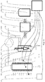
- the heat pump thereby comprises a cooling medium circuit consisting of a compressor 101, a condenser 102, a cooling medium supply 103, an expansion valve 104 and an evaporator 105.
- a control unit 106 which controls its function is also associated with the circuit.
- What is characterizing the invention is a by-pass channel 200 by-passing at least the cooling medium supply 103 and the expansion valve 104, and having a by-pass valve 201 provided in the by-pass channel 200.
- the by-pass channel 200 by-passes also the condenser 102.
- the invention includes
- the open by-pass channel according to point 1 passes the compressor power of about 1-2 kW into the evaporator 105 which becomes heated. Above all the coldest parts of the evaporator are heated, where the heaviest frosting can be expected. Thereby the ice will rapidly melt away from the metal in the evaporator, possible loose frost residues will be completely exposed to the outflowing air and will rapidly melt away. In this way a defrosting, which using traditional methods normally will take at least about 10 minutes (20% of the normal time between two defrosting operations) will be effected in less than two minutes (4% of this time).
- the cooling medium dome 301 will not add any defrosting function by themselves. However, when the pressure in the dome rapidly decreases due to the by-pass channel 200 opening, the cooling medium condensate contents of the dome will flow in huge amounts through the warm condenser 102 where it immediately is supplied with large heat energy amounts from the heat exchanger of condenser 102 (power of about 30 to 40 kW can be expected), rapidly boils and flows over to the cold evaporator 105 where it rapidly condenses and again releases its 30 to 40 kW. These added 30 to 40 kW will melt away all frost in less than ten seconds (0,33% of the normal time between two consecutive defrosting actions). Possibly the meltwater could require an additional ten seconds for leaving the evaporator. All in all a complete defrosting of the condenser 105 in less than 20 seconds ( ⁇ 0,7% of the normal time between two consecutive defrosting actions).
- the new invention is defined in claim 1.
- the invention relates to modification of a conventional cooling medium circuit, Fig. 1 , in a heat pump.
- the modification is defined above in the descriptions relating to Figs 2-6 .
- the conventional cooling medium circuit comprises a closed loop having, in order, the following components: a compressor 101, a condensor 102, a cooling medium supply 103 (sometimes referred to as a "receiver"), an expansion valve 104 and an evaporator 105.
- the flow through the cooling medium circuit is controlled by a dedicated machine control unit 106.
- the modification comprises:
- Fig. 4 as an example, the heat pump of Fig. 2 is shown supplemented with a cooling medium dome 301 tempered by return water 1122 and coupled to the cooling medium circuit.
- a cooling medium dome 301 tempered by return water 1122 and coupled to the cooling medium circuit.
- the connection of the4 dome 301 should always be located on the opposite side of the condenser 102 relative the bypass conduit 202. In this case at the condenser outlet.
- the cooling medium dome 301 comprises a closed container, coupled to the high pressure side of the cooling medium circuit at the bottom part via an open connection tube.
- the connection tube must thus be coupled to the cooling medium circuit somewhere between the compressor outlet 101u and the cooling medium supply 103. Additionally the best effect is achieved if the connection is located on the opposite side of the condenser 102 relative the connection of the bypass channel 200.
- Cooling medium will flow freely through the connection between dome 301 and cooling medium circuit such that all pressure differences between the dome and the circuit will be eliminated immediately. Due to the connection being located in the bottom of the dome, the outflow from the dome will however always consist of cooling medium condensate that might occur, since condensate will collect at the bottom of the dome.
- the inflow can on the contrary comprise vapour as well as condensate, fully dependent on the current phase of the medium in the connection to the cooling medium circuit.
- the medium pressure is determined by the conditions in the condenser and correspond to the condensation pressure of the medium at the current condensation temperature. Since the dome 301 is tempered to a temperature that during normal operation always is below the condenser temperature (when the dome 301 is tempered by exhaust air this means that the condenser temperature should not be below the exhaust air temperature, which by any reasonable standard very rarely happens), the pressure inside the dome during normal operation will substantially exceed the condensation pressure of the cooling medium at current temperature, and hence all cooling medium vapour in the dome 301 will condense and allow inflow of further cooling medium. Thereby the dome 301 after a short period of normal operation or in power reduced operation to be completely filled with cooling medium condensate.
- the medium pressure will be the same as the current very low condensation pressure in the cold evaporator.
- a small partial amount of the tempered condensate contents in the dome 301 will then rapidly be flash evaporated and drive all of the remaining condensate out into the cooling medium circuit, further on through the hot condenser for rapid heat uptake, evaporation, expansion and further flow through the wide open bypass channel 200 into the cold evaporator 105.
- the hot steam will rapidly release its heat energy and condense. This energy transfer can be expected to be largest in the coldest parts of the evaporator, i.e. those parts that carry most frost.
- the frost matter will thereby rapidly thaw from the inside, come off the evaporator material and be blown away by the exhaust air flow and subsequent possible further thawing and to run off as liquid.
- the total energy contents in the cooling medium vapour from the dome condensate should be at least as large as the energy that is required for thawing the frost material on the evaporator.
- the "smallest allowable" volume of the dome 301 is thus determined by the volume of condensate that it must be able to house. This volume is in its turn determined by the amount of ice that has to be melted, the heat of melting per liter of the ice and the heat of evaporation of the current cooling medium per liter of condensate.
- the melting heat of the ice per liter melt water at zero degrees Celsius can be set to 335 kJ.
- Fig. 7 shows the heat pump of Fig. 6 in normal operation.
- the bypass valve is maintained fully closed and the function of the machine completely corresponds to that of a traditional machine according to Fig. 1 .
- the temperature in the condenser 102 thereby exceeds the incoming temperature of the circulating flow and also to even greater extent its return temperature.
- the pressure in the condenser 102 in turn exceeds the pressure of condensation of the cooling medium at current temperature. Typical values in this state of operation is about 3°C for the temperature difference across the condensor heat exchanger, and about 6kW for the transfer power to the circulating water.
- the same pressure prevails during normal operation as in the cooling medium and the condenser 102, but substantially lower temperature, far below the temperature of the cooling medium in the dome 301 at current pressure.
- Any vapour phase of the cooling in the dome will therefore condense and the volume reduction due to the transfer of vapour to condensate is compensated by a corresponding inflow of cooling medium, in liquid and/or gas phase, from the cooling medium circuit. Any gas that has flown in will condense and new cooling medium will flow in etc.
- the dome 301 is completely filled with cooling medium condensate.
- Transition to defrosting operation takes place when the bypass valve 201between the high pressure and low pressure sides of the system is opened. Due to the pressure drop that occurs on the high pressure side a vigorous boiling off of existing cooling medium condensate in the warm condenser 102 occurs. Large amounts of evaporated cooling medium and accompanying large amounts of energy are formed in the condenser 102 and flows out via the condenser inlet and bypass conduit 202 to the evaporator 105 where they immediately are condensed and release their energy. See further under Fig. 8 .
- Fig. 8 shows the heat pump of Fig. 7 I defrosting operation.
- the bypass valve 201 is held open at maximum, and there is an almost total pressure levelling between evaporator 105 and condenser 102.
- the condenser pressure becomes much lower than in normal operation and will be very much lower than the evaporation pressure in the condenser 102 and in the communicating cooling medium dome 301.
- Any and all cooling medium condensate in the condenser 102 will thus be rapidly flash evaporated during heavy energy uptake, whereby the condenser temperature is lowered to a new equilibrium temperature, substantially lower than in normal operation.
- the temperature reduction in the condenser 102 brings about a large temperature deficit in the cooling medium relative the circulating water.
- the temperature deficit in turn causes a very heavy heat flow through the condenser heat exchanger from the circulating water and into the cooling medium, where it drives the evaporation process further.
- a typical value for the heat exchanging capacity of the condenser 102 is 2 kW per degree of temperature difference. At the new equilibrium temperature one can expect a temperature difference across the heat exchanger of fifteen to twenty degrees, which in turn gives a transfer power of about 30 to 40 kW which supplies energy to the evaporation process in the condensor.
- the vapour formed flows out of the condenser outlet, bringing with it its about 30 to 40 kW of heat power, and further on through the bypass conduit 202 to the evaporator inlet.
- the compressor 101 circulates all its flow, against a very low counter-pressure, through the evaporator 105 where the input compressor power (in principle only the idle power of the compressor) contributes a little further to the energy supply.
- the pressure levelling will in a corresponding manner provide a pressure that is much higher than during normal operation and which is far above the condensation pressure at the current evaporator temperature.
- the cooling medium vapour in the evaporator 105 is condensed and releases its about 30 to 40 kW inside the evaporator 105, the inner temperature of which is very rapidly increased to such an extent that the released heat power can flow further on and out through the evaporator heat exchanger and reach the cold outside of the evaporator 105 where the temperature almost immediately rises to the melting temperature of the water and rapidly causes the frost to begin melting.
- the evaporator 105 has a neat exchanging capacity of about 2 kW per degree of temperature difference, and hence the released heat power of about 30 to 40 kW causes an equilibrium temperature about 15 to 20 degrees above the 0 degrees prevailing in the melt water on the outside of the evaporator 105.
- cooling medium condensate 3011 will collect in the evaporator 105 and in any condensate depots during defrosting. This collected amount of condensate will rapidly evaporate on transition to normal operation and will in less than one minute via the compressor return the used defrosting heat to the circulating water.
- the machine is kept in defrosting operation by the control unit 203 as long as, but only that long, there is any frost remaining on the evaporator 105. Due to the very efficient defrosting, the total time in this state will be extremely short, not more than a few seconds, which is almost neglectable compared to the total time for a corresponding conventional defrosting. Also, the energy consumption and energy loss due to defrosting will be so much lower than what it would have been during traditional exhaust air driven defrosting.
- the control unit 203 places the machine in defrosting operation at even time intervals in order to keep the accumulated amount of frost on the evaporator 105 on an optimal level.
- optimal level is to be understood the level that over a complete heating/defrosting cycle yields the highest average heat power production and the highest average COP, in a mutual optimal balance.
- the control unit 203 also monitors the defrosting process and closes the bypass valve 201 as soon as all frost has been removed from the evaporator 105.
- Figs. 10 and 11 show the heat pump of Fig.2 and 6 , respectively, in power reduced operation.
- the bypass valve is controlled by the control unit 203 to let a suitable portion of the hot gas flow from the compressor 101 pass directly to the evaporator inlet.
- the gas flow and power flow into the condenser 102 will be reduced as will pressure and temperature in the condenser 102.
- the medium flow into the evaporator inlet will be affected to be as desired and suitable in terms of temperature, pressure and extent of flow.
- Fig. 12 shows the principle for a particularly highly efficient version of the cooling medium dome.
Landscapes
- Engineering & Computer Science (AREA)
- Physics & Mathematics (AREA)
- Mechanical Engineering (AREA)
- Thermal Sciences (AREA)
- General Engineering & Computer Science (AREA)
- Chemical & Material Sciences (AREA)
- Combustion & Propulsion (AREA)
- Heat-Pump Type And Storage Water Heaters (AREA)
- Defrosting Systems (AREA)
Applications Claiming Priority (1)
| Application Number | Priority Date | Filing Date | Title |
|---|---|---|---|
| SE1650658A SE542633C2 (sv) | 2016-05-17 | 2016-05-17 | Anordning för snabbavfrostning utan kompressorstopp av förångaren i en luft-vatten-värmepump och för att köra värmepumpen vid extremt låga förångartemepraturer och vid extremt lågalaster |
Publications (1)
| Publication Number | Publication Date |
|---|---|
| EP3246641A1 true EP3246641A1 (fr) | 2017-11-22 |
Family
ID=59276482
Family Applications (1)
| Application Number | Title | Priority Date | Filing Date |
|---|---|---|---|
| EP17171090.8A Withdrawn EP3246641A1 (fr) | 2016-05-17 | 2017-05-15 | Appareil de dégivrage rapide d'évaporateur dans une pompe à chaleur air-eau |
Country Status (2)
| Country | Link |
|---|---|
| EP (1) | EP3246641A1 (fr) |
| SE (1) | SE542633C2 (fr) |
Cited By (3)
| Publication number | Priority date | Publication date | Assignee | Title |
|---|---|---|---|---|
| WO2019146070A1 (fr) * | 2018-01-26 | 2019-08-01 | 三菱電機株式会社 | Dispositif à cycle de réfrigération |
| CN110454944A (zh) * | 2019-08-26 | 2019-11-15 | 重庆美的通用制冷设备有限公司 | 空调器的控制方法、装置及空调器 |
| CN112888586A (zh) * | 2018-12-21 | 2021-06-01 | 大众汽车股份公司 | 用于运行电动车辆的热泵的方法 |
Citations (8)
| Publication number | Priority date | Publication date | Assignee | Title |
|---|---|---|---|---|
| US4646539A (en) * | 1985-11-06 | 1987-03-03 | Thermo King Corporation | Transport refrigeration system with thermal storage sink |
| JPH07248166A (ja) * | 1994-03-14 | 1995-09-26 | Nippondenso Co Ltd | 冷凍装置 |
| US20050132729A1 (en) * | 2003-12-23 | 2005-06-23 | Manole Dan M. | Transcritical vapor compression system and method of operating including refrigerant storage tank and non-variable expansion device |
| JP2007170758A (ja) * | 2005-12-22 | 2007-07-05 | Sanden Corp | 冷凍装置 |
| WO2009140370A2 (fr) * | 2008-05-14 | 2009-11-19 | Carrier Corporation | Gestion de la charge dans des systèmes de réfrigération à compression de vapeur |
| GB2487975A (en) * | 2011-02-11 | 2012-08-15 | Frigesco Ltd | Flash defrost system |
| WO2014092152A1 (fr) * | 2012-12-14 | 2014-06-19 | シャープ株式会社 | Cycle de réfrigération et climatiseur équipé de celui-ci |
| WO2014098724A1 (fr) * | 2012-12-21 | 2014-06-26 | Fläkt Woods AB | Procédé et appareil de dégivrage d'un évaporateur en relation avec une unité de conditionnement d'air |
-
2016
- 2016-05-17 SE SE1650658A patent/SE542633C2/sv not_active IP Right Cessation
-
2017
- 2017-05-15 EP EP17171090.8A patent/EP3246641A1/fr not_active Withdrawn
Patent Citations (8)
| Publication number | Priority date | Publication date | Assignee | Title |
|---|---|---|---|---|
| US4646539A (en) * | 1985-11-06 | 1987-03-03 | Thermo King Corporation | Transport refrigeration system with thermal storage sink |
| JPH07248166A (ja) * | 1994-03-14 | 1995-09-26 | Nippondenso Co Ltd | 冷凍装置 |
| US20050132729A1 (en) * | 2003-12-23 | 2005-06-23 | Manole Dan M. | Transcritical vapor compression system and method of operating including refrigerant storage tank and non-variable expansion device |
| JP2007170758A (ja) * | 2005-12-22 | 2007-07-05 | Sanden Corp | 冷凍装置 |
| WO2009140370A2 (fr) * | 2008-05-14 | 2009-11-19 | Carrier Corporation | Gestion de la charge dans des systèmes de réfrigération à compression de vapeur |
| GB2487975A (en) * | 2011-02-11 | 2012-08-15 | Frigesco Ltd | Flash defrost system |
| WO2014092152A1 (fr) * | 2012-12-14 | 2014-06-19 | シャープ株式会社 | Cycle de réfrigération et climatiseur équipé de celui-ci |
| WO2014098724A1 (fr) * | 2012-12-21 | 2014-06-26 | Fläkt Woods AB | Procédé et appareil de dégivrage d'un évaporateur en relation avec une unité de conditionnement d'air |
Cited By (3)
| Publication number | Priority date | Publication date | Assignee | Title |
|---|---|---|---|---|
| WO2019146070A1 (fr) * | 2018-01-26 | 2019-08-01 | 三菱電機株式会社 | Dispositif à cycle de réfrigération |
| CN112888586A (zh) * | 2018-12-21 | 2021-06-01 | 大众汽车股份公司 | 用于运行电动车辆的热泵的方法 |
| CN110454944A (zh) * | 2019-08-26 | 2019-11-15 | 重庆美的通用制冷设备有限公司 | 空调器的控制方法、装置及空调器 |
Also Published As
| Publication number | Publication date |
|---|---|
| SE1650658A1 (sv) | 2017-11-18 |
| SE542633C2 (sv) | 2020-06-23 |
Similar Documents
| Publication | Publication Date | Title |
|---|---|---|
| KR100757580B1 (ko) | 공조용 히트 펌프 | |
| KR101192346B1 (ko) | 히트 펌프식 급탕장치 | |
| CN105716355B (zh) | 一种风冷冰箱辅助除霜装置及方法 | |
| CN101929753A (zh) | 双工况制冰制冷水的制冷系统 | |
| CN102725597A (zh) | 集装箱用冷冻装置 | |
| CN109844423B (zh) | 具有在输入侧和输出侧耦联的热泵装置的热泵系统 | |
| JP2012163219A (ja) | ヒートポンプシステム | |
| KR101619016B1 (ko) | 핫가스 제상 사이클을 갖는 냉동 장치 | |
| JP4317793B2 (ja) | 冷却システム | |
| EP3246641A1 (fr) | Appareil de dégivrage rapide d'évaporateur dans une pompe à chaleur air-eau | |
| JP2004218861A (ja) | ヒートポンプ式給湯器におけるドレンパン凍結防止構造 | |
| KR100939614B1 (ko) | 태양열 시스템의 온수를 이용한 냉방기 | |
| WO2023223898A1 (fr) | Procédé de démarrage d'un système de gestion thermique pour véhicules électriques et système de gestion thermique associé | |
| CN105650872A (zh) | 一种热水器 | |
| US6311507B1 (en) | Refrigeration system with minimum pre-set condensing pressure | |
| CN208431976U (zh) | 一种二氧化碳载冷剂制冷系统 | |
| CN204115322U (zh) | 热氟融霜装置 | |
| CN109791006B (zh) | 具有co2作为第一热泵介质和水作为第二热泵介质的热泵系统 | |
| CN211424781U (zh) | 一种热气融霜系统 | |
| CN206222814U (zh) | 一种节能冷库热回收利用设备 | |
| JP2012137218A (ja) | 空気冷媒式冷凍装置のデフロスト方法及び装置 | |
| CN104132473A (zh) | 两级压缩不间断制热装置及两级压缩不间断制热融霜方法 | |
| CN101688710B (zh) | 用于在吸收式冷却器中进行排热的方法和系统 | |
| KR101962878B1 (ko) | 냉동기 토출 가스에 의한 응축 폐열 회수를 이용한 냉동 시스템 | |
| CN110793246A (zh) | 一种热气融霜系统及热气融霜方法 |
Legal Events
| Date | Code | Title | Description |
|---|---|---|---|
| PUAI | Public reference made under article 153(3) epc to a published international application that has entered the european phase |
Free format text: ORIGINAL CODE: 0009012 |
|
| STAA | Information on the status of an ep patent application or granted ep patent |
Free format text: STATUS: THE APPLICATION HAS BEEN PUBLISHED |
|
| AK | Designated contracting states |
Kind code of ref document: A1 Designated state(s): AL AT BE BG CH CY CZ DE DK EE ES FI FR GB GR HR HU IE IS IT LI LT LU LV MC MK MT NL NO PL PT RO RS SE SI SK SM TR |
|
| AX | Request for extension of the european patent |
Extension state: BA ME |
|
| STAA | Information on the status of an ep patent application or granted ep patent |
Free format text: STATUS: REQUEST FOR EXAMINATION WAS MADE |
|
| 17P | Request for examination filed |
Effective date: 20180508 |
|
| RBV | Designated contracting states (corrected) |
Designated state(s): AL AT BE BG CH CY CZ DE DK EE ES FI FR GB GR HR HU IE IS IT LI LT LU LV MC MK MT NL NO PL PT RO RS SE SI SK SM TR |
|
| GRAP | Despatch of communication of intention to grant a patent |
Free format text: ORIGINAL CODE: EPIDOSNIGR1 |
|
| STAA | Information on the status of an ep patent application or granted ep patent |
Free format text: STATUS: GRANT OF PATENT IS INTENDED |
|
| INTG | Intention to grant announced |
Effective date: 20210607 |
|
| STAA | Information on the status of an ep patent application or granted ep patent |
Free format text: STATUS: THE APPLICATION IS DEEMED TO BE WITHDRAWN |
|
| 18D | Application deemed to be withdrawn |
Effective date: 20211019 |