EP3246685A1 - Élément sensible à la pression, capteur de pression, et procédé de fabrication d'un élément sensible à la pression - Google Patents
Élément sensible à la pression, capteur de pression, et procédé de fabrication d'un élément sensible à la pression Download PDFInfo
- Publication number
- EP3246685A1 EP3246685A1 EP15747084.0A EP15747084A EP3246685A1 EP 3246685 A1 EP3246685 A1 EP 3246685A1 EP 15747084 A EP15747084 A EP 15747084A EP 3246685 A1 EP3246685 A1 EP 3246685A1
- Authority
- EP
- European Patent Office
- Prior art keywords
- pressure sensing
- sensing element
- film
- sensor
- insulating layer
- Prior art date
- Legal status (The legal status is an assumption and is not a legal conclusion. Google has not performed a legal analysis and makes no representation as to the accuracy of the status listed.)
- Granted
Links
Images




Classifications
-
- G—PHYSICS
- G01—MEASURING; TESTING
- G01L—MEASURING FORCE, STRESS, TORQUE, WORK, MECHANICAL POWER, MECHANICAL EFFICIENCY, OR FLUID PRESSURE
- G01L1/00—Measuring force or stress, in general
- G01L1/20—Measuring force or stress, in general by measuring variations in ohmic resistance of solid materials or of electrically-conductive fluids; by making use of electrokinetic cells, i.e. liquid-containing cells wherein an electrical potential is produced or varied upon the application of stress
- G01L1/22—Measuring force or stress, in general by measuring variations in ohmic resistance of solid materials or of electrically-conductive fluids; by making use of electrokinetic cells, i.e. liquid-containing cells wherein an electrical potential is produced or varied upon the application of stress using resistance strain gauges
- G01L1/2287—Measuring force or stress, in general by measuring variations in ohmic resistance of solid materials or of electrically-conductive fluids; by making use of electrokinetic cells, i.e. liquid-containing cells wherein an electrical potential is produced or varied upon the application of stress using resistance strain gauges constructional details of the strain gauges
-
- A—HUMAN NECESSITIES
- A61—MEDICAL OR VETERINARY SCIENCE; HYGIENE
- A61B—DIAGNOSIS; SURGERY; IDENTIFICATION
- A61B5/00—Measuring for diagnostic purposes; Identification of persons
- A61B5/44—Detecting, measuring or recording for evaluating the integumentary system, e.g. skin, hair or nails
- A61B5/441—Skin evaluation, e.g. for skin disorder diagnosis
- A61B5/447—Skin evaluation, e.g. for skin disorder diagnosis specially adapted for aiding the prevention of ulcer or pressure sore development, i.e. before the ulcer or sore has developed
-
- G—PHYSICS
- G01—MEASURING; TESTING
- G01L—MEASURING FORCE, STRESS, TORQUE, WORK, MECHANICAL POWER, MECHANICAL EFFICIENCY, OR FLUID PRESSURE
- G01L1/00—Measuring force or stress, in general
- G01L1/20—Measuring force or stress, in general by measuring variations in ohmic resistance of solid materials or of electrically-conductive fluids; by making use of electrokinetic cells, i.e. liquid-containing cells wherein an electrical potential is produced or varied upon the application of stress
- G01L1/205—Measuring force or stress, in general by measuring variations in ohmic resistance of solid materials or of electrically-conductive fluids; by making use of electrokinetic cells, i.e. liquid-containing cells wherein an electrical potential is produced or varied upon the application of stress using distributed sensing elements
-
- G—PHYSICS
- G01—MEASURING; TESTING
- G01L—MEASURING FORCE, STRESS, TORQUE, WORK, MECHANICAL POWER, MECHANICAL EFFICIENCY, OR FLUID PRESSURE
- G01L5/00—Apparatus for, or methods of, measuring force, work, mechanical power, or torque, specially adapted for specific purposes
-
- A—HUMAN NECESSITIES
- A61—MEDICAL OR VETERINARY SCIENCE; HYGIENE
- A61B—DIAGNOSIS; SURGERY; IDENTIFICATION
- A61B2562/00—Details of sensors; Constructional details of sensor housings or probes; Accessories for sensors
- A61B2562/02—Details of sensors specially adapted for in-vivo measurements
- A61B2562/0247—Pressure sensors
-
- A—HUMAN NECESSITIES
- A61—MEDICAL OR VETERINARY SCIENCE; HYGIENE
- A61B—DIAGNOSIS; SURGERY; IDENTIFICATION
- A61B2562/00—Details of sensors; Constructional details of sensor housings or probes; Accessories for sensors
- A61B2562/04—Arrangements of multiple sensors of the same type
- A61B2562/046—Arrangements of multiple sensors of the same type in a matrix array
-
- A—HUMAN NECESSITIES
- A61—MEDICAL OR VETERINARY SCIENCE; HYGIENE
- A61B—DIAGNOSIS; SURGERY; IDENTIFICATION
- A61B2562/00—Details of sensors; Constructional details of sensor housings or probes; Accessories for sensors
- A61B2562/12—Manufacturing methods specially adapted for producing sensors for in-vivo measurements
-
- A—HUMAN NECESSITIES
- A61—MEDICAL OR VETERINARY SCIENCE; HYGIENE
- A61B—DIAGNOSIS; SURGERY; IDENTIFICATION
- A61B2562/00—Details of sensors; Constructional details of sensor housings or probes; Accessories for sensors
- A61B2562/16—Details of sensor housings or probes; Details of structural supports for sensors
- A61B2562/164—Details of sensor housings or probes; Details of structural supports for sensors the sensor is mounted in or on a conformable substrate or carrier
-
- G—PHYSICS
- G01—MEASURING; TESTING
- G01L—MEASURING FORCE, STRESS, TORQUE, WORK, MECHANICAL POWER, MECHANICAL EFFICIENCY, OR FLUID PRESSURE
- G01L5/00—Apparatus for, or methods of, measuring force, work, mechanical power, or torque, specially adapted for specific purposes
- G01L5/22—Apparatus for, or methods of, measuring force, work, mechanical power, or torque, specially adapted for specific purposes for measuring the force applied to control members, e.g. control members of vehicles, triggers
- G01L5/226—Apparatus for, or methods of, measuring force, work, mechanical power, or torque, specially adapted for specific purposes for measuring the force applied to control members, e.g. control members of vehicles, triggers to manipulators, e.g. the force due to gripping
- G01L5/228—Apparatus for, or methods of, measuring force, work, mechanical power, or torque, specially adapted for specific purposes for measuring the force applied to control members, e.g. control members of vehicles, triggers to manipulators, e.g. the force due to gripping using tactile array force sensors
Definitions
- a pressure sensing element In the automotive field, for example, it has been general to embed a pressure sensing element into a seat. This is aimed at prompting a passenger who gets on a vehicle and sits on the seat to fasten a seat belt. More specifically, upon sitting of the passenger on the vehicle seat, a predetermined level or larger load (weight) is applied to the pressure sensing element. Accordingly, a pressure sensor equipped with the pressure sensing element senses the presence of the passenger, and prompts him or her to fasten the seat belt.
- Patent Literature 1 listed below describes a stacked structure of a pressure sensor in which one circuit board having a sensor electrode provided thereon, and the other circuit board having a pressure sensitive resistor formed thereon by printing, are opposed while placing a spacer sheet in between (see Table 2 in this literature).
- the spacer sheet is a PET film having tacky layers formed on both surfaces thereof, and on both surfaces of which, the one circuit board and the other circuit board are bonded.
- Patent Literature 2 listed below is configured by a resistor board and an electrode support substrate, which are bonded while placing in between a spacer composed of an adhesion layer (see paragraph [0031] of this literature).
- the literature describes that the adhesion layer is an acrylic tacky film or the like.
- a pressure sensor which includes the pressure sensing element of this invention; and a detection unit which is electrically connected to the pressure sensing element and detects contact resistance between the pressure sensing film and the sensor electrode.
- a method of manufacturing a pressure sensing element of this invention includes an electrode forming step, forming a sensor electrode on at least one surface of a support substrate; a coating step, coating a photo-sensitive coating material so as to cover the support substrate and the sensor electrode; an insulating layer forming step, forming an insulating layer by exposing and developing the photo-sensitive coating material, the insulating layer having an opening which is partitioned by an aperture wall and an aperture end, and allows therein the sensor electrode to expose; and a pressure sensing film forming step, forming a pressure sensing film by placing a resin film, functionalized to be electro-conductive, so as to blanket the insulating layer, the coating step which includes a step of coating the photo-sensitive coating material by a screen printing technique, and the insulating layer forming step, succeeding to the coating step, which includes exposing and developing the photo-sensitive coating material, according to the guidelines (1) and (2) below, to thereby form the opening in the insulating layer:
- the pressure sensing element of this invention can demonstrate a good initial detection sensitivity both in the flat state and in the bent state, and can prevent short-circuiting in the initial state. It is therefore fully compatible to use in a wide variety of fields.
- the method of manufacturing a pressure sensing element of this invention can easily manufacture the pressure sensing element of this invention.
- the various constituents of this invention are not always necessarily be independent entities, instead allowing for example that a plurality of constituents are formed as a single member, that a single constituent is formed by a plurality of members, that one constituent forms a part of other constituent, and that a part of one constituent overlaps a part of other constituent.
- membrane, sheet and film are synonymous and are not discriminative, and embrace so-called panel and plate.
- initial state means a state where the pressure sensing film stays unpressurized from outside.
- Dynamic range means the range of change of contact resistance between the sensor electrode and the pressure sensing film.
- Initial detection sensitivity means sensitivity with which the initial pressure sensing load is detected.
- Initial pressure sensing load means a minimum pressurizing force under which electrical conduction in the sensor electrode is detectable, when the pressure sensing film is pressurized from the outside, and the pressure sensing film and the sensor electrode are brought into contact.
- electrical conduction is detectable means either that current or voltage not smaller than a predetermined threshold value is detected, or that current or voltage substantially exceeding zero is detected.
- the initial detection sensitivity preferably falls within a predetermined range. This is because, the detection will be insufficient if the initial detection sensitivity is too low, meanwhile even a very small load unintended for detection may be detected to cause erroneous detection if the initial detection sensitivity is too high.
- FIG. 1 is a plan view illustrating the pressure sensor 200 according to a first embodiment of this invention.
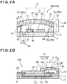
- FIG. 2A is a cross sectional view taken along line I-I in FIG. 1
- FIG. 2B is a cross sectional view taken along line II-II in FIG. 1 .
- FIG. 3A to FIG. 3C are plan views illustrating a modified example of a sensor electrode 12.
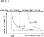
- FIG. 4 is an explanatory drawing explaining the initial detection sensitivity and dynamic range of the pressure sensing element 100 of the first embodiment.
- a curve 110 illustrated in FIG. 4 merely indicates a tendency of the dynamic range of the pressure sensing element 100, without limiting this invention.
- the pressure sensing element 100 of this embodiment is a single-channel type element configured by a pressure sensor part 15 having a single sensor electrode 12 and a pressure sensing film 14 opposed to each other.
- the pressure sensing element 100 and pressure sensor 200 of this embodiment will be outlined.
- the pressure sensing element 100 has a support substrate 11, the sensor electrode 12 supported on the support substrate 11, a pressure sensing film 14 functionalized to be electro-conductive, at least in a portion thereof faced to the sensor electrode 12, and an insulating layer 13.
- the insulating layer 13 keeps the sensor electrode 12 and the pressure sensing film 14 apart from each other by a predetermined distance A, and has formed therein an opening 20 in which the sensor electrode 12 is exposed to the pressure sensing film 14.
- the insulating layer 13 has an aperture wall 13b which partitions the opening 20, and an aperture end (top aperture end 13a) faced to the pressure sensing film 14.
- the insulating layer 13 is characteristically increased in height, measured from the support substrate 11, continuously towards the opening 20.
- the pressure sensor 200 of this embodiment has the pressure sensing element 100, and a detection unit 210 which is electrically connected to the pressure sensing element 100 and detects contact resistance between the pressure sensing film 14 and the sensor electrode 12.
- the pressure sensing element 100 of this embodiment is a device, whose measurable physical quantity varies depending on load of pressurizing force from the outside.
- the pressure sensing element 100 when applied with pressurizing force from the outside, causes changes in the contact resistance between the pressure sensing film 14 and the sensor electrode 12.
- a first electrode 12a and a second electrode 12b are connected to an unillustrated current source. In the initial state, as illustrated in FIG. 2A and FIG. 2B , the pressure sensing film 14 and the sensor electrode 12 are kept apart, and are not electrically connected.
- the pressure sensing element 100 While being secured with the predetermined distance "A" for keeping the sensor electrode 12 and the pressure sensing film 14 apart (also simply referred to as the "predetermined distance A”, hereinafter), the pressure sensing element 100 is successfully prevented from causing short-circuiting when mounted on a flat surface, that is, in the initial state.
- the distance A in this invention represents, as illustrated in FIG. 2A , the difference between height H2 of a top aperture end 13a of the insulating layer 13, and height H3 of the sensor electrode 12.
- the pressure sensing film 14 which is stacked on the insulating layer 13 having the slope 22 inclines conforming to the slope 22.
- the inclination of the surface over the opening 20 is oriented to bulge towards the side opposite to the support substrate 11 (also referred to a "first direction", hereinafter). Accordingly, even if the pressure sensing element 100 is bent in the first direction, the pressure sensing film 14 and the sensor electrode 12 are less likely to approach each other, and thereby the short-circuiting is avoidable.
- the surface of the pressure sensing film 14 over the opening 20 is oriented to bulge towards the first direction includes the case where the pressure sensing film 14 over the opening 20 bulges towards the first direction, and the case where it is kept nearly flat.
- the case where "the pressure sensing film 14 over the opening 20 bulges in the first direction” may conveniently be referred to the pressure sensing film 14 which appears in FIG. 2A and FIG. 2B or on the right side of FIG. 9D .
- the case where "the pressure sensing film 14 over the opening 20 is kept nearly flat” may conveniently be referred to the pressure sensing film 14 which appears in the left side of FIG. 9D .
- the pressure sensing element 100 of this embodiment has the support substrate 11 which supports the sensor electrode 12.
- the support substrate 11 has formed on one surface thereof the sensor electrode 12, and has stacked thereon the insulating layer 13 having the opening 20 formed therein, and the pressure sensing film 14.
- the thus manufactured sensor electrode 12 is further plated in a predetermined region thereof. More specifically, the surface of the sensor electrode 12, faced to the pressure sensing film 14, is plated. By the plating, the sensor electrode 12 may be prevented from being oxidized or degraded, and may be improved in the wear resistance against the pressure sensing film 14 which is repetitively pressed thereon. The plating may be given during, or succeeding to, the film making process of the sensor electrode 12.
- the plating is specifically exemplified by, but not limited to, nickel plating with a thickness of approximately 2 ⁇ m or larger and 10 ⁇ m or smaller, and gold plating with a thickness of approximately 0.02 ⁇ m or larger and 0.20 ⁇ m or smaller.
- the height 3H (see FIG. 2A ) of such suitably plated sensor electrode 12 typically falls in, but not specifically limited to, the range from 10 ⁇ m or larger and 45 ⁇ m or smaller, from the practical viewpoint.
- Height H3 of the sensor electrode 12, and/or, height H2 of the top aperture end 13a in the insulating layer 13, which will be described later, are preferably controlled so that the predetermined distance A may be controlled to a suitable level.
- the insulating layer 13 having the opening 20 formed therein may be formed, for example, by coating a photo-sensitive coating material 174 by a printing technique over the support substrate 11 having the sensor electrode 12 provided thereto, followed by exposure and development.
- the slope 22 may be formed to a certain level of significance by controlling the viscosity of the photo-sensitive coating material 174, prompt exposure after the coating by printing, exposure conditions and so forth.
- the photo-sensitive coating material 174 formed by printing would be leveled, and would fail in producing a desired amount of variation in the level of height of the insulating layer 13.
- the insulating layer 13 may be formed by a technique other than printing. For example, a film material having the opening 20 preliminarily formed at a predetermined position, and embossed to form projections around the opening 20 may be used as the insulating layer 13, and may be bonded to the support substrate 11.
- the slope 22 which extends up to a point approximately 1 mm away from the side faces of the sensor electrode 12 faced to the aperture wall 13b. Accordingly, by controlling distance D5 to 850 ⁇ m or shorter, the slope 22 may surely be formed in the region containing distance D5. Meanwhile, with distance D5 controlled to 50 ⁇ m or longer, development failure will be avoidable, and even in case of accidental misalignment in the exposure process, the sensor electrode 12 and the insulating layer 13 may be prevented from overlapping with each other.
- the insulating layer 13 may alternatively be formed by aligning and bonding a tacky sheet or adhesive sheet, having preliminarily formed therein the opening 20 and the slope 22 which surrounds the opening 20, to the top surface of the support substrate 11.
- the pressure sensing film 14 is a component which is brought into contact with the sensor electrode 12, to electrify the pair of the first electrode 12a and the second electrode 12b, which configure the sensor electrode 12.
- the pressure sensing film 14 is functionalized to be electro-conductive" means that the pressure sensing film 14 is electro-conductive, only enough to electrify the sensor electrode 12 through the pressure sensing film 14 when pressed externally. More specifically, the pressure sensing film 14 which is externally loaded by pressurizing force is brought into contact with the first electrode 12a and the second electrode 12b so as to bridge them, and thereby the first electrode 12a and the second electrode 12b are electrically connected.
- the pressure sensing film 14 in this embodiment is a resin film containing a carbon particle 140, as illustrated in FIG. 2A and FIG. 2B .
- the pressure sensing film 14 is functionalized to be electro-conductive with the carbon particle 140.
- the resin film used as the pressure sensing film 14 contains just as much amount of the carbon particle 140 necessary for demonstrating an electro-conductive function.
- the resin film is flexible. With such electro-conductive function of the resin film per se, the pressure sensing film 14 may be thinned, a good flexibility is ensured, and the dynamic range of the pressure sensing element 100 may be increased. Since the electro-conductive resin film is used as the pressure sensing film 14, so as to configure the touch area, so that the pressure sensing film 14 is less likely to make the user, who externally touches it, feel like something is wrong.
- the pressure sensing element 100 may be controlled so that the surface of the pressure sensing film 14, faced to the sensor electrode 12, has a surface roughness Rz of 0.10 ⁇ m or larger and 0.50 ⁇ m or smaller. By such control, a good formability of the pressure sensing film 14 is ensured, and detection sensitivity of contact resistance is stabilized.
- the insulating layer 13 has openings 20 through which the pressure sensing film 14 is opposed to the sensor electrodes 12 while placing the hollow space S in between.
- the adhesion layer 30 has apertures 30a.
- Each aperture 30a contains, in a plan view, the upper aperture 20a of each opening.
- the aperture 30a is larger than the upper aperture 20a of the opening 20 in a plan view, and therefore contains the upper aperture 20a. With such configuration, the adhesive which composes the adhesion layer 30 may be prevented from entering the hollow space S out from the upper aperture 20a.
- predetermined values in the context of the guideline (1) and the guideline (2) may represent either predetermined range or predetermined value. This manufacturing method encompasses both cases where the predetermined value in the guideline (1) and the predetermined value in the guideline (2) are same, and different.
- the steps 1 to 6 represent an exemplary mode of the electrode forming step.
- the screen plate 172 preferably used here is exemplified by a polyester mesh having a mesh count of #120 (general commercial product), and a 3D-woven stainless steel mesh (3D-165-126, from Asada Mesh Co., Ltd.) having a mesh count of #165, but not limited thereto. It is also preferable to prebake the photo-sensitive coated film 176, after formed, just enough to smooth out the tuck on the surface of the photo-sensitive coated film 176. It is also preferable to control the viscosity of the photo-sensitive coating material 174, or timing of exposure, so that the photo-sensitive coating material 174 will not be leveled, and thereby the photo-sensitive coated film 176 will not be planarized.
- an adhesive sheet having been punched out at portions corresponded to the individual openings 20 may be laminated with the pressure sensing film 14 to form the adhesion layer 30, and the obtained stack may be bonded to the insulating layer 30 while placing the adhesion layer 30 in between as described later. In all cases, the adhesion layer 30 will not reach the top aperture end 13a.
- the steps below are optionally implemented. More specifically, in order to make the external terminal electrodes 12d appropriately rigid, a reinforcing plate (not illustrated) is formed on the external terminal electrodes 12d.
- the reinforcing plate is generally composed of a plate made of metal such as stainless steel or aluminum, or a film made of polyimide or polyethylene terephthalate, having a desired thickness, and is laminated with the external terminal electrodes 12d using a tacky agent or adhesive.
- Precision punching of the external terminal electrodes 12d is followed by a step of contour punching for determining overall contour of the pressure sensing element 300.
- the pressure sensing element 300 is manufactured by the steps 1 to 15 described above. The thus manufactured pressure sensing element 300 is then checked in terms of dimension of the individual portions, conduction performance of the sensor electrodes 12 and the lead wires 12c, and pressure-sensitive resistivity characteristic, and those satisfied certain standards are shipped as accepted products. Alternatively, the pressure sensing element 300 obtained above may be electrically connected with the detection unit 210 to manufacture the pressure sensor 400. If the pressure sensing element 300 manufactured as described above has the sensor electrodes 12 and the lead wires 12c provided only on one surface thereof, the CCL with the support substrate 11 may be processed in the form of roll which is passed through steps 1 to 15 form.
- the pressure sensing element 300 thus manufactured is shown in FIG. 9D , in which a pressure sensor part 15a (15) on the left hand side of the drawing has a larger aperture size of the opening 20, and a lower height of the top aperture end 13a, than those of the pressure sensor part 15b (15) on the right hand side of the drawing. Accordingly, the pressure sensor part 15a (15) has an initial pressure sensing load smaller than that of the pressure sensor part 15b (15).
- the pressure sensor 400 of this invention may be disposed over a part, or entire portion, of an area modeled on the human hand, to implement a hand-shaped, or glove-type pressure sensor.
- a pressure sensor 200 having the pressure sensing element 100 composed of a single sensor electrode 12, may be used while being placed on a surface with a complex texture, in the same way as for the pressure sensor 400.
- the photo-sensitive coated film 176 was formed by screen printing as described below. More specifically, on the top surface of the printing work, the screen plate 172 which is a 120-mesh ( 120) polyester mesh was placed so as to be mounted on the sensor electrode 12, and so as to be landed on the surface of the support substrate 11 around the sensor electrode 12 (see FIG. 9A ). The squeegee 170 was moved along the screen plate 172 so as to coat the photo-sensitive coating material 174 onto the printing work, and the screen plate 172 was then removed, to thereby obtain the printing work having the photo-sensitive coated film 176 formed thereon by coating the photo-sensitive coating material 174 (see FIG. 11 ).
- the screen plate 172 which is a 120-mesh ( 120) polyester mesh was placed so as to be mounted on the sensor electrode 12, and so as to be landed on the surface of the support substrate 11 around the sensor electrode 12 (see FIG. 9A ).
- the squeegee 170 was moved along the screen plate 172 so as to coat the photo-sensitive
- the above-obtained printing work having the photo-sensitive coated film 176 was embedded in an acrylic resin to thereby manufacture a test piece.
- the test piece was then sliced in the direction of normal line of the support substrate 11, at individual positions "a" to “l” indicated in FIG. 11 , and the cross sections were polished to give the individual samples to be measured.
- Values of distance D5 measured from the sensor electrode 12 (side face of the second electrode 12b) to the individual positions "a" to “l” were summarized in Table 1.
- the pressure sensors 200 of Examples and Comparative Examples obtained above were subjected to evaluation of pressure sensing characteristics described below.
- Five samples were prepared and evaluated for every Example and every Comparative Example.
- the pressure sensor 200 was rated as "not observed” if short-circuiting was not observed for all of five samples, and rated as "observed” if short-circuiting was observed in any one of five samples. Results of the evaluations are summarized in Table 3.
- Each of the pressure sensors 200 of Examples and Comparative Examples was placed on a flat surface, and the pressure sensor part 15 was gradually loaded from the outside of the pressure sensing film 14. The load under which electric conduction is initially detected was determined as initial pressure sensing load (N).
- Each of the pressure sensors 200 of Examples, Comparative Examples, and Reference Example was placed on a flat surface, and the pressure sensor part 15 having an area of 4 mm 2 was loaded with a load of 1.1 MPa (112.5 gf/mm 2 ), under which the resistivity ( ⁇ ) was measured.
- each of the pressure sensors 200 of Examples and Comparative Examples showed the initial pressure sensing load in the range from 0.1 N or larger and 0.7 N or smaller, and the sensor resistivity under large load in the range from 500 ⁇ or larger and 2500 ⁇ or smaller, proving good pressure sensing characteristics.
- Comparative Example 1 having a distance D5 of zero, was found to show development failure, due to misalignment of exposure in the step of forming the insulating layer 13.
Landscapes
- Health & Medical Sciences (AREA)
- Physics & Mathematics (AREA)
- Life Sciences & Earth Sciences (AREA)
- General Physics & Mathematics (AREA)
- Heart & Thoracic Surgery (AREA)
- Surgery (AREA)
- Engineering & Computer Science (AREA)
- Biomedical Technology (AREA)
- Biophysics (AREA)
- Medical Informatics (AREA)
- Molecular Biology (AREA)
- Pathology (AREA)
- Animal Behavior & Ethology (AREA)
- General Health & Medical Sciences (AREA)
- Public Health (AREA)
- Veterinary Medicine (AREA)
- Dermatology (AREA)
- Force Measurement Appropriate To Specific Purposes (AREA)
Applications Claiming Priority (1)
| Application Number | Priority Date | Filing Date | Title |
|---|---|---|---|
| PCT/JP2015/050817 WO2016113867A1 (fr) | 2015-01-14 | 2015-01-14 | Élément sensible à la pression, capteur de pression, et procédé de fabrication d'un élément sensible à la pression |
Publications (3)
| Publication Number | Publication Date |
|---|---|
| EP3246685A1 true EP3246685A1 (fr) | 2017-11-22 |
| EP3246685A4 EP3246685A4 (fr) | 2018-05-23 |
| EP3246685B1 EP3246685B1 (fr) | 2020-05-06 |
Family
ID=54200725
Family Applications (1)
| Application Number | Title | Priority Date | Filing Date |
|---|---|---|---|
| EP15747084.0A Not-in-force EP3246685B1 (fr) | 2015-01-14 | 2015-01-14 | Élément sensible à la pression, capteur de pression, et procédé de fabrication d'un élément sensible à la pression |
Country Status (4)
| Country | Link |
|---|---|
| US (1) | US9574955B2 (fr) |
| EP (1) | EP3246685B1 (fr) |
| JP (1) | JP5782582B1 (fr) |
| WO (1) | WO2016113867A1 (fr) |
Cited By (7)
| Publication number | Priority date | Publication date | Assignee | Title |
|---|---|---|---|---|
| EP3222394A2 (fr) * | 2016-03-25 | 2017-09-27 | Seiko Epson Corporation | Robot et dispositif de détection de force externe |
| US10670479B2 (en) | 2018-02-27 | 2020-06-02 | Methode Electronics, Inc. | Towing systems and methods using magnetic field sensing |
| US10696109B2 (en) | 2017-03-22 | 2020-06-30 | Methode Electronics Malta Ltd. | Magnetolastic based sensor assembly |
| US11084342B2 (en) | 2018-02-27 | 2021-08-10 | Methode Electronics, Inc. | Towing systems and methods using magnetic field sensing |
| US11135882B2 (en) | 2018-02-27 | 2021-10-05 | Methode Electronics, Inc. | Towing systems and methods using magnetic field sensing |
| US11221262B2 (en) | 2018-02-27 | 2022-01-11 | Methode Electronics, Inc. | Towing systems and methods using magnetic field sensing |
| US11491832B2 (en) | 2018-02-27 | 2022-11-08 | Methode Electronics, Inc. | Towing systems and methods using magnetic field sensing |
Families Citing this family (18)
| Publication number | Priority date | Publication date | Assignee | Title |
|---|---|---|---|---|
| US12114995B2 (en) | 2014-11-10 | 2024-10-15 | Walgreen Health Solutions, Llc | Wireless pressure-sensitive dressing assemblies and wireless monitoring systems equipped therewith |
| JP6530687B2 (ja) * | 2015-09-24 | 2019-06-12 | 日本メクトロン株式会社 | 感圧素子および圧力センサ |
| JP6772506B2 (ja) * | 2016-03-25 | 2020-10-21 | セイコーエプソン株式会社 | ロボット |
| GB2550411B (en) * | 2016-05-20 | 2019-04-03 | Hp1 Tech Ltd | Device for detecting a force |
| WO2018052096A1 (fr) * | 2016-09-14 | 2018-03-22 | ソニー株式会社 | Capteur, dispositif d'entrée, et dispositif électronique |
| JP6982953B2 (ja) * | 2016-09-21 | 2021-12-17 | エルジー ディスプレイ カンパニー リミテッド | センサ装置 |
| JP6997533B2 (ja) * | 2017-04-28 | 2022-01-17 | 日東電工株式会社 | 生体センサ用シート |
| CN107479757B (zh) * | 2017-08-25 | 2020-07-14 | 上海天马微电子有限公司 | 显示面板和显示装置 |
| US11014417B2 (en) | 2018-02-27 | 2021-05-25 | Methode Electronics, Inc. | Towing systems and methods using magnetic field sensing |
| CN108613759B (zh) * | 2018-05-03 | 2020-06-02 | 湖南厚生医疗器械有限公司 | 一种触觉传感器皮肤 |
| KR102103171B1 (ko) * | 2018-08-27 | 2020-06-01 | (주)모어씽즈 | 정전식 센서와 저항식 센서를 통합한 하이브리드 대면적 압력 센서 |
| JP7099908B2 (ja) * | 2018-08-30 | 2022-07-12 | トヨタ自動車株式会社 | センサシステム、ロボットハンド、センサシステムの較正方法、およびプログラム |
| KR102666867B1 (ko) * | 2018-12-13 | 2024-05-21 | 삼성디스플레이 주식회사 | 표시장치 |
| US11422332B2 (en) * | 2019-02-01 | 2022-08-23 | Tdk Taiwan Corp. | Driving mechanism |
| CN211507472U (zh) * | 2020-04-24 | 2020-09-15 | 湃瑞电子科技(苏州)有限公司 | 一种压力传感器及其按键结构和按键模组 |
| CN111595491B (zh) * | 2020-05-18 | 2021-08-31 | 重庆大学 | 一种低串扰可无限细分的矩阵式触觉传感单元 |
| FR3130786B1 (fr) * | 2021-12-17 | 2023-12-15 | Nanomade Labs | Micro-capteur à électrodes interdigitées |
| WO2023136041A1 (fr) * | 2022-01-17 | 2023-07-20 | 株式会社フジクラ | Unité de capteur sensible à la pression |
Family Cites Families (9)
| Publication number | Priority date | Publication date | Assignee | Title |
|---|---|---|---|---|
| US5878620A (en) | 1997-01-23 | 1999-03-09 | Schlege Systems, Inc. | Conductive fabric sensor for vehicle seats |
| LU90286B1 (fr) | 1998-09-11 | 2000-03-13 | Iee Sarl | Capteur de force |
| JP2001159569A (ja) | 1999-12-02 | 2001-06-12 | Denso Corp | 感圧センサ |
| JP3980300B2 (ja) | 2000-09-07 | 2007-09-26 | 株式会社フジクラ | 膜状感圧抵抗体および感圧センサ |
| US6909354B2 (en) * | 2001-02-08 | 2005-06-21 | Interlink Electronics, Inc. | Electronic pressure sensitive transducer apparatus and method for manufacturing same |
| JP2004028883A (ja) | 2002-06-27 | 2004-01-29 | Denso Corp | 感圧センサ |
| WO2007107525A1 (fr) * | 2006-03-17 | 2007-09-27 | Iee International Electronics & Engineering S.A. | Capteur de pression |
| LU91810B1 (en) * | 2011-04-22 | 2012-10-23 | Iee Sarl | Footwear article with pressure sensor |
| JP2012247372A (ja) * | 2011-05-30 | 2012-12-13 | Nippon Mektron Ltd | 圧力センサ及びその製造方法並びに圧力検出モジュール |
-
2015
- 2015-01-14 US US14/769,290 patent/US9574955B2/en not_active Expired - Fee Related
- 2015-01-14 WO PCT/JP2015/050817 patent/WO2016113867A1/fr not_active Ceased
- 2015-01-14 JP JP2015515750A patent/JP5782582B1/ja not_active Expired - Fee Related
- 2015-01-14 EP EP15747084.0A patent/EP3246685B1/fr not_active Not-in-force
Cited By (8)
| Publication number | Priority date | Publication date | Assignee | Title |
|---|---|---|---|---|
| EP3222394A2 (fr) * | 2016-03-25 | 2017-09-27 | Seiko Epson Corporation | Robot et dispositif de détection de force externe |
| US10696109B2 (en) | 2017-03-22 | 2020-06-30 | Methode Electronics Malta Ltd. | Magnetolastic based sensor assembly |
| US10940726B2 (en) | 2017-03-22 | 2021-03-09 | Methode Electronics Malta Ltd. | Magnetoelastic based sensor assembly |
| US10670479B2 (en) | 2018-02-27 | 2020-06-02 | Methode Electronics, Inc. | Towing systems and methods using magnetic field sensing |
| US11084342B2 (en) | 2018-02-27 | 2021-08-10 | Methode Electronics, Inc. | Towing systems and methods using magnetic field sensing |
| US11135882B2 (en) | 2018-02-27 | 2021-10-05 | Methode Electronics, Inc. | Towing systems and methods using magnetic field sensing |
| US11221262B2 (en) | 2018-02-27 | 2022-01-11 | Methode Electronics, Inc. | Towing systems and methods using magnetic field sensing |
| US11491832B2 (en) | 2018-02-27 | 2022-11-08 | Methode Electronics, Inc. | Towing systems and methods using magnetic field sensing |
Also Published As
| Publication number | Publication date |
|---|---|
| EP3246685A4 (fr) | 2018-05-23 |
| US9574955B2 (en) | 2017-02-21 |
| WO2016113867A1 (fr) | 2016-07-21 |
| US20160363491A1 (en) | 2016-12-15 |
| JPWO2016113867A1 (ja) | 2017-04-27 |
| EP3246685B1 (fr) | 2020-05-06 |
| JP5782582B1 (ja) | 2015-09-24 |
Similar Documents
| Publication | Publication Date | Title |
|---|---|---|
| EP3246685B1 (fr) | Élément sensible à la pression, capteur de pression, et procédé de fabrication d'un élément sensible à la pression | |
| US10048141B2 (en) | Pressure sensing element and pressure sensor | |
| US10359326B2 (en) | Pressure sensor capable of suppressing dispersion in the initial load of pressure | |
| US9423309B2 (en) | Pressure sensor, method for manufacture thereof, and pressure detection module | |
| US10034370B2 (en) | Stretchable circuit board and method for manufacturing stretchable circuit board | |
| JP5995362B2 (ja) | 分布量センサおよび分布量計測システム | |
| EP2833111A1 (fr) | Capteur capacitif | |
| JP2001165788A (ja) | 感圧装置 | |
| TW201209664A (en) | Pressure detecting unit and information input device having pressure detecting unit | |
| KR102180901B1 (ko) | 용이한 압력 분포 확인 구조를 갖는 압저항형 압력센서 | |
| US20240280422A1 (en) | Shear force sensor, and detection unit for shear force sensor | |
| US20150199048A1 (en) | Touch panel assembly | |
| JP2018105775A (ja) | フレキシブルデバイス | |
| JP2024164789A (ja) | 応力センサ | |
| JP2012057992A (ja) | 感圧センサー | |
| TWI778684B (zh) | 感壓電路板及感壓電路板的製作方法 | |
| JPH0426134B2 (fr) | ||
| JP2015145881A (ja) | 圧力センサ | |
| CN118518001B (zh) | 一种含缝阵列的电阻柔性应变传感器及其制备方法 | |
| WO2025154440A1 (fr) | Capteur de charge | |
| KR102472286B1 (ko) | 압력 감지 센서 | |
| JP2018112405A (ja) | 感圧センサ | |
| JP2025089937A (ja) | 応力センサ | |
| CN119173730A (zh) | 一种传感装置 | |
| JPS615328A (ja) | 情報入力用タブレツト |
Legal Events
| Date | Code | Title | Description |
|---|---|---|---|
| STAA | Information on the status of an ep patent application or granted ep patent |
Free format text: STATUS: THE INTERNATIONAL PUBLICATION HAS BEEN MADE |
|
| PUAI | Public reference made under article 153(3) epc to a published international application that has entered the european phase |
Free format text: ORIGINAL CODE: 0009012 |
|
| STAA | Information on the status of an ep patent application or granted ep patent |
Free format text: STATUS: REQUEST FOR EXAMINATION WAS MADE |
|
| 17P | Request for examination filed |
Effective date: 20150814 |
|
| AK | Designated contracting states |
Kind code of ref document: A1 Designated state(s): AL AT BE BG CH CY CZ DE DK EE ES FI FR GB GR HR HU IE IS IT LI LT LU LV MC MK MT NL NO PL PT RO RS SE SI SK SM TR |
|
| AX | Request for extension of the european patent |
Extension state: BA ME |
|
| DAX | Request for extension of the european patent (deleted) | ||
| A4 | Supplementary search report drawn up and despatched |
Effective date: 20180423 |
|
| RIC1 | Information provided on ipc code assigned before grant |
Ipc: G01L 1/22 20060101ALI20180417BHEP Ipc: G01L 5/00 20060101ALI20180417BHEP Ipc: G01L 1/20 20060101AFI20180417BHEP Ipc: G01L 5/22 20060101ALI20180417BHEP Ipc: A61B 5/00 20060101ALI20180417BHEP |
|
| STAA | Information on the status of an ep patent application or granted ep patent |
Free format text: STATUS: EXAMINATION IS IN PROGRESS |
|
| 17Q | First examination report despatched |
Effective date: 20190228 |
|
| GRAP | Despatch of communication of intention to grant a patent |
Free format text: ORIGINAL CODE: EPIDOSNIGR1 |
|
| STAA | Information on the status of an ep patent application or granted ep patent |
Free format text: STATUS: GRANT OF PATENT IS INTENDED |
|
| INTG | Intention to grant announced |
Effective date: 20191213 |
|
| GRAS | Grant fee paid |
Free format text: ORIGINAL CODE: EPIDOSNIGR3 |
|
| GRAA | (expected) grant |
Free format text: ORIGINAL CODE: 0009210 |
|
| STAA | Information on the status of an ep patent application or granted ep patent |
Free format text: STATUS: THE PATENT HAS BEEN GRANTED |
|
| AK | Designated contracting states |
Kind code of ref document: B1 Designated state(s): AL AT BE BG CH CY CZ DE DK EE ES FI FR GB GR HR HU IE IS IT LI LT LU LV MC MK MT NL NO PL PT RO RS SE SI SK SM TR |
|
| REG | Reference to a national code |
Ref country code: GB Ref legal event code: FG4D |
|
| REG | Reference to a national code |
Ref country code: AT Ref legal event code: REF Ref document number: 1267536 Country of ref document: AT Kind code of ref document: T Effective date: 20200515 Ref country code: CH Ref legal event code: EP |
|
| REG | Reference to a national code |
Ref country code: IE Ref legal event code: FG4D |
|
| REG | Reference to a national code |
Ref country code: DE Ref legal event code: R096 Ref document number: 602015052219 Country of ref document: DE |
|
| REG | Reference to a national code |
Ref country code: LT Ref legal event code: MG4D |
|
| REG | Reference to a national code |
Ref country code: NL Ref legal event code: MP Effective date: 20200506 |
|
| PG25 | Lapsed in a contracting state [announced via postgrant information from national office to epo] |
Ref country code: PT Free format text: LAPSE BECAUSE OF FAILURE TO SUBMIT A TRANSLATION OF THE DESCRIPTION OR TO PAY THE FEE WITHIN THE PRESCRIBED TIME-LIMIT Effective date: 20200907 Ref country code: SE Free format text: LAPSE BECAUSE OF FAILURE TO SUBMIT A TRANSLATION OF THE DESCRIPTION OR TO PAY THE FEE WITHIN THE PRESCRIBED TIME-LIMIT Effective date: 20200506 Ref country code: IS Free format text: LAPSE BECAUSE OF FAILURE TO SUBMIT A TRANSLATION OF THE DESCRIPTION OR TO PAY THE FEE WITHIN THE PRESCRIBED TIME-LIMIT Effective date: 20200906 Ref country code: LT Free format text: LAPSE BECAUSE OF FAILURE TO SUBMIT A TRANSLATION OF THE DESCRIPTION OR TO PAY THE FEE WITHIN THE PRESCRIBED TIME-LIMIT Effective date: 20200506 Ref country code: NO Free format text: LAPSE BECAUSE OF FAILURE TO SUBMIT A TRANSLATION OF THE DESCRIPTION OR TO PAY THE FEE WITHIN THE PRESCRIBED TIME-LIMIT Effective date: 20200806 Ref country code: GR Free format text: LAPSE BECAUSE OF FAILURE TO SUBMIT A TRANSLATION OF THE DESCRIPTION OR TO PAY THE FEE WITHIN THE PRESCRIBED TIME-LIMIT Effective date: 20200807 Ref country code: FI Free format text: LAPSE BECAUSE OF FAILURE TO SUBMIT A TRANSLATION OF THE DESCRIPTION OR TO PAY THE FEE WITHIN THE PRESCRIBED TIME-LIMIT Effective date: 20200506 |
|
| PG25 | Lapsed in a contracting state [announced via postgrant information from national office to epo] |
Ref country code: HR Free format text: LAPSE BECAUSE OF FAILURE TO SUBMIT A TRANSLATION OF THE DESCRIPTION OR TO PAY THE FEE WITHIN THE PRESCRIBED TIME-LIMIT Effective date: 20200506 Ref country code: LV Free format text: LAPSE BECAUSE OF FAILURE TO SUBMIT A TRANSLATION OF THE DESCRIPTION OR TO PAY THE FEE WITHIN THE PRESCRIBED TIME-LIMIT Effective date: 20200506 Ref country code: RS Free format text: LAPSE BECAUSE OF FAILURE TO SUBMIT A TRANSLATION OF THE DESCRIPTION OR TO PAY THE FEE WITHIN THE PRESCRIBED TIME-LIMIT Effective date: 20200506 Ref country code: BG Free format text: LAPSE BECAUSE OF FAILURE TO SUBMIT A TRANSLATION OF THE DESCRIPTION OR TO PAY THE FEE WITHIN THE PRESCRIBED TIME-LIMIT Effective date: 20200806 |
|
| REG | Reference to a national code |
Ref country code: AT Ref legal event code: MK05 Ref document number: 1267536 Country of ref document: AT Kind code of ref document: T Effective date: 20200506 |
|
| PG25 | Lapsed in a contracting state [announced via postgrant information from national office to epo] |
Ref country code: AL Free format text: LAPSE BECAUSE OF FAILURE TO SUBMIT A TRANSLATION OF THE DESCRIPTION OR TO PAY THE FEE WITHIN THE PRESCRIBED TIME-LIMIT Effective date: 20200506 Ref country code: NL Free format text: LAPSE BECAUSE OF FAILURE TO SUBMIT A TRANSLATION OF THE DESCRIPTION OR TO PAY THE FEE WITHIN THE PRESCRIBED TIME-LIMIT Effective date: 20200506 |
|
| PG25 | Lapsed in a contracting state [announced via postgrant information from national office to epo] |
Ref country code: AT Free format text: LAPSE BECAUSE OF FAILURE TO SUBMIT A TRANSLATION OF THE DESCRIPTION OR TO PAY THE FEE WITHIN THE PRESCRIBED TIME-LIMIT Effective date: 20200506 Ref country code: SM Free format text: LAPSE BECAUSE OF FAILURE TO SUBMIT A TRANSLATION OF THE DESCRIPTION OR TO PAY THE FEE WITHIN THE PRESCRIBED TIME-LIMIT Effective date: 20200506 Ref country code: RO Free format text: LAPSE BECAUSE OF FAILURE TO SUBMIT A TRANSLATION OF THE DESCRIPTION OR TO PAY THE FEE WITHIN THE PRESCRIBED TIME-LIMIT Effective date: 20200506 Ref country code: CZ Free format text: LAPSE BECAUSE OF FAILURE TO SUBMIT A TRANSLATION OF THE DESCRIPTION OR TO PAY THE FEE WITHIN THE PRESCRIBED TIME-LIMIT Effective date: 20200506 Ref country code: EE Free format text: LAPSE BECAUSE OF FAILURE TO SUBMIT A TRANSLATION OF THE DESCRIPTION OR TO PAY THE FEE WITHIN THE PRESCRIBED TIME-LIMIT Effective date: 20200506 Ref country code: IT Free format text: LAPSE BECAUSE OF FAILURE TO SUBMIT A TRANSLATION OF THE DESCRIPTION OR TO PAY THE FEE WITHIN THE PRESCRIBED TIME-LIMIT Effective date: 20200506 Ref country code: ES Free format text: LAPSE BECAUSE OF FAILURE TO SUBMIT A TRANSLATION OF THE DESCRIPTION OR TO PAY THE FEE WITHIN THE PRESCRIBED TIME-LIMIT Effective date: 20200506 Ref country code: DK Free format text: LAPSE BECAUSE OF FAILURE TO SUBMIT A TRANSLATION OF THE DESCRIPTION OR TO PAY THE FEE WITHIN THE PRESCRIBED TIME-LIMIT Effective date: 20200506 |
|
| REG | Reference to a national code |
Ref country code: DE Ref legal event code: R097 Ref document number: 602015052219 Country of ref document: DE |
|
| PG25 | Lapsed in a contracting state [announced via postgrant information from national office to epo] |
Ref country code: SK Free format text: LAPSE BECAUSE OF FAILURE TO SUBMIT A TRANSLATION OF THE DESCRIPTION OR TO PAY THE FEE WITHIN THE PRESCRIBED TIME-LIMIT Effective date: 20200506 Ref country code: PL Free format text: LAPSE BECAUSE OF FAILURE TO SUBMIT A TRANSLATION OF THE DESCRIPTION OR TO PAY THE FEE WITHIN THE PRESCRIBED TIME-LIMIT Effective date: 20200506 |
|
| PLBE | No opposition filed within time limit |
Free format text: ORIGINAL CODE: 0009261 |
|
| STAA | Information on the status of an ep patent application or granted ep patent |
Free format text: STATUS: NO OPPOSITION FILED WITHIN TIME LIMIT |
|
| 26N | No opposition filed |
Effective date: 20210209 |
|
| PG25 | Lapsed in a contracting state [announced via postgrant information from national office to epo] |
Ref country code: SI Free format text: LAPSE BECAUSE OF FAILURE TO SUBMIT A TRANSLATION OF THE DESCRIPTION OR TO PAY THE FEE WITHIN THE PRESCRIBED TIME-LIMIT Effective date: 20200506 |
|
| PG25 | Lapsed in a contracting state [announced via postgrant information from national office to epo] |
Ref country code: MC Free format text: LAPSE BECAUSE OF FAILURE TO SUBMIT A TRANSLATION OF THE DESCRIPTION OR TO PAY THE FEE WITHIN THE PRESCRIBED TIME-LIMIT Effective date: 20200506 |
|
| REG | Reference to a national code |
Ref country code: CH Ref legal event code: PL |
|
| GBPC | Gb: european patent ceased through non-payment of renewal fee |
Effective date: 20210114 |
|
| PG25 | Lapsed in a contracting state [announced via postgrant information from national office to epo] |
Ref country code: LU Free format text: LAPSE BECAUSE OF NON-PAYMENT OF DUE FEES Effective date: 20210114 |
|
| REG | Reference to a national code |
Ref country code: BE Ref legal event code: MM Effective date: 20210131 |
|
| PG25 | Lapsed in a contracting state [announced via postgrant information from national office to epo] |
Ref country code: FR Free format text: LAPSE BECAUSE OF NON-PAYMENT OF DUE FEES Effective date: 20210131 |
|
| PG25 | Lapsed in a contracting state [announced via postgrant information from national office to epo] |
Ref country code: CH Free format text: LAPSE BECAUSE OF NON-PAYMENT OF DUE FEES Effective date: 20210131 Ref country code: LI Free format text: LAPSE BECAUSE OF NON-PAYMENT OF DUE FEES Effective date: 20210131 Ref country code: GB Free format text: LAPSE BECAUSE OF NON-PAYMENT OF DUE FEES Effective date: 20210114 |
|
| PG25 | Lapsed in a contracting state [announced via postgrant information from national office to epo] |
Ref country code: IE Free format text: LAPSE BECAUSE OF NON-PAYMENT OF DUE FEES Effective date: 20210114 |
|
| PG25 | Lapsed in a contracting state [announced via postgrant information from national office to epo] |
Ref country code: BE Free format text: LAPSE BECAUSE OF NON-PAYMENT OF DUE FEES Effective date: 20210131 |
|
| PG25 | Lapsed in a contracting state [announced via postgrant information from national office to epo] |
Ref country code: HU Free format text: LAPSE BECAUSE OF FAILURE TO SUBMIT A TRANSLATION OF THE DESCRIPTION OR TO PAY THE FEE WITHIN THE PRESCRIBED TIME-LIMIT; INVALID AB INITIO Effective date: 20150114 |
|
| PG25 | Lapsed in a contracting state [announced via postgrant information from national office to epo] |
Ref country code: CY Free format text: LAPSE BECAUSE OF FAILURE TO SUBMIT A TRANSLATION OF THE DESCRIPTION OR TO PAY THE FEE WITHIN THE PRESCRIBED TIME-LIMIT Effective date: 20200506 |
|
| PG25 | Lapsed in a contracting state [announced via postgrant information from national office to epo] |
Ref country code: MK Free format text: LAPSE BECAUSE OF FAILURE TO SUBMIT A TRANSLATION OF THE DESCRIPTION OR TO PAY THE FEE WITHIN THE PRESCRIBED TIME-LIMIT Effective date: 20200506 |
|
| PGFP | Annual fee paid to national office [announced via postgrant information from national office to epo] |
Ref country code: DE Payment date: 20231128 Year of fee payment: 10 |
|
| PG25 | Lapsed in a contracting state [announced via postgrant information from national office to epo] |
Ref country code: TR Free format text: LAPSE BECAUSE OF FAILURE TO SUBMIT A TRANSLATION OF THE DESCRIPTION OR TO PAY THE FEE WITHIN THE PRESCRIBED TIME-LIMIT Effective date: 20200506 |
|
| PG25 | Lapsed in a contracting state [announced via postgrant information from national office to epo] |
Ref country code: MT Free format text: LAPSE BECAUSE OF FAILURE TO SUBMIT A TRANSLATION OF THE DESCRIPTION OR TO PAY THE FEE WITHIN THE PRESCRIBED TIME-LIMIT Effective date: 20200506 |
|
| REG | Reference to a national code |
Ref country code: DE Ref legal event code: R081 Ref document number: 602015052219 Country of ref document: DE Owner name: MEKTEC CORPORATION, JP Free format text: FORMER OWNER: NIPPON MEKTRON, LTD., TOKYO, JP |
|
| REG | Reference to a national code |
Ref country code: DE Ref legal event code: R119 Ref document number: 602015052219 Country of ref document: DE |
|
| PG25 | Lapsed in a contracting state [announced via postgrant information from national office to epo] |
Ref country code: DE Free format text: LAPSE BECAUSE OF NON-PAYMENT OF DUE FEES Effective date: 20250801 |