EP3246719A1 - Dispositif de surveillance de batterie avec émulateur de batterie - Google Patents
Dispositif de surveillance de batterie avec émulateur de batterie Download PDFInfo
- Publication number
- EP3246719A1 EP3246719A1 EP17164013.9A EP17164013A EP3246719A1 EP 3246719 A1 EP3246719 A1 EP 3246719A1 EP 17164013 A EP17164013 A EP 17164013A EP 3246719 A1 EP3246719 A1 EP 3246719A1
- Authority
- EP
- European Patent Office
- Prior art keywords
- signal
- physical
- battery
- battery cells
- monitoring device
- Prior art date
- Legal status (The legal status is an assumption and is not a legal conclusion. Google has not performed a legal analysis and makes no representation as to the accuracy of the status listed.)
- Granted
Links
Images



Classifications
-
- B—PERFORMING OPERATIONS; TRANSPORTING
- B60—VEHICLES IN GENERAL
- B60L—PROPULSION OF ELECTRICALLY-PROPELLED VEHICLES; SUPPLYING ELECTRIC POWER FOR AUXILIARY EQUIPMENT OF ELECTRICALLY-PROPELLED VEHICLES; ELECTRODYNAMIC BRAKE SYSTEMS FOR VEHICLES IN GENERAL; MAGNETIC SUSPENSION OR LEVITATION FOR VEHICLES; MONITORING OPERATING VARIABLES OF ELECTRICALLY-PROPELLED VEHICLES; ELECTRIC SAFETY DEVICES FOR ELECTRICALLY-PROPELLED VEHICLES
- B60L58/00—Methods or circuit arrangements for monitoring or controlling batteries or fuel cells, specially adapted for electric vehicles
- B60L58/10—Methods or circuit arrangements for monitoring or controlling batteries or fuel cells, specially adapted for electric vehicles for monitoring or controlling batteries
- B60L58/12—Methods or circuit arrangements for monitoring or controlling batteries or fuel cells, specially adapted for electric vehicles for monitoring or controlling batteries responding to state of charge [SoC]
- B60L58/15—Preventing overcharging
-
- B—PERFORMING OPERATIONS; TRANSPORTING
- B60—VEHICLES IN GENERAL
- B60L—PROPULSION OF ELECTRICALLY-PROPELLED VEHICLES; SUPPLYING ELECTRIC POWER FOR AUXILIARY EQUIPMENT OF ELECTRICALLY-PROPELLED VEHICLES; ELECTRODYNAMIC BRAKE SYSTEMS FOR VEHICLES IN GENERAL; MAGNETIC SUSPENSION OR LEVITATION FOR VEHICLES; MONITORING OPERATING VARIABLES OF ELECTRICALLY-PROPELLED VEHICLES; ELECTRIC SAFETY DEVICES FOR ELECTRICALLY-PROPELLED VEHICLES
- B60L58/00—Methods or circuit arrangements for monitoring or controlling batteries or fuel cells, specially adapted for electric vehicles
- B60L58/10—Methods or circuit arrangements for monitoring or controlling batteries or fuel cells, specially adapted for electric vehicles for monitoring or controlling batteries
- B60L58/18—Methods or circuit arrangements for monitoring or controlling batteries or fuel cells, specially adapted for electric vehicles for monitoring or controlling batteries of two or more battery modules
- B60L58/20—Methods or circuit arrangements for monitoring or controlling batteries or fuel cells, specially adapted for electric vehicles for monitoring or controlling batteries of two or more battery modules having different nominal voltages
-
- B—PERFORMING OPERATIONS; TRANSPORTING
- B60—VEHICLES IN GENERAL
- B60L—PROPULSION OF ELECTRICALLY-PROPELLED VEHICLES; SUPPLYING ELECTRIC POWER FOR AUXILIARY EQUIPMENT OF ELECTRICALLY-PROPELLED VEHICLES; ELECTRODYNAMIC BRAKE SYSTEMS FOR VEHICLES IN GENERAL; MAGNETIC SUSPENSION OR LEVITATION FOR VEHICLES; MONITORING OPERATING VARIABLES OF ELECTRICALLY-PROPELLED VEHICLES; ELECTRIC SAFETY DEVICES FOR ELECTRICALLY-PROPELLED VEHICLES
- B60L58/00—Methods or circuit arrangements for monitoring or controlling batteries or fuel cells, specially adapted for electric vehicles
- B60L58/10—Methods or circuit arrangements for monitoring or controlling batteries or fuel cells, specially adapted for electric vehicles for monitoring or controlling batteries
- B60L58/12—Methods or circuit arrangements for monitoring or controlling batteries or fuel cells, specially adapted for electric vehicles for monitoring or controlling batteries responding to state of charge [SoC]
-
- B—PERFORMING OPERATIONS; TRANSPORTING
- B60—VEHICLES IN GENERAL
- B60W—CONJOINT CONTROL OF VEHICLE SUB-UNITS OF DIFFERENT TYPE OR DIFFERENT FUNCTION; CONTROL SYSTEMS SPECIALLY ADAPTED FOR HYBRID VEHICLES; ROAD VEHICLE DRIVE CONTROL SYSTEMS FOR PURPOSES NOT RELATED TO THE CONTROL OF A PARTICULAR SUB-UNIT
- B60W10/00—Conjoint control of vehicle sub-units of different type or different function
- B60W10/04—Conjoint control of vehicle sub-units of different type or different function including control of propulsion units
- B60W10/08—Conjoint control of vehicle sub-units of different type or different function including control of propulsion units including control of electric propulsion units, e.g. motors or generators
-
- B—PERFORMING OPERATIONS; TRANSPORTING
- B60—VEHICLES IN GENERAL
- B60W—CONJOINT CONTROL OF VEHICLE SUB-UNITS OF DIFFERENT TYPE OR DIFFERENT FUNCTION; CONTROL SYSTEMS SPECIALLY ADAPTED FOR HYBRID VEHICLES; ROAD VEHICLE DRIVE CONTROL SYSTEMS FOR PURPOSES NOT RELATED TO THE CONTROL OF A PARTICULAR SUB-UNIT
- B60W10/00—Conjoint control of vehicle sub-units of different type or different function
- B60W10/24—Conjoint control of vehicle sub-units of different type or different function including control of energy storage means
- B60W10/26—Conjoint control of vehicle sub-units of different type or different function including control of energy storage means for electrical energy, e.g. batteries or capacitors
-
- B—PERFORMING OPERATIONS; TRANSPORTING
- B60—VEHICLES IN GENERAL
- B60W—CONJOINT CONTROL OF VEHICLE SUB-UNITS OF DIFFERENT TYPE OR DIFFERENT FUNCTION; CONTROL SYSTEMS SPECIALLY ADAPTED FOR HYBRID VEHICLES; ROAD VEHICLE DRIVE CONTROL SYSTEMS FOR PURPOSES NOT RELATED TO THE CONTROL OF A PARTICULAR SUB-UNIT
- B60W30/00—Purposes of road vehicle drive control systems not related to the control of a particular sub-unit, e.g. of systems using conjoint control of vehicle sub-units
- B60W30/18—Propelling the vehicle
-
- G—PHYSICS
- G01—MEASURING; TESTING
- G01R—MEASURING ELECTRIC VARIABLES; MEASURING MAGNETIC VARIABLES
- G01R31/00—Arrangements for testing electric properties; Arrangements for locating electric faults; Arrangements for electrical testing characterised by what is being tested not provided for elsewhere
- G01R31/36—Arrangements for testing, measuring or monitoring the electrical condition of accumulators or electric batteries, e.g. capacity or state of charge [SoC]
- G01R31/3644—Constructional arrangements
- G01R31/3648—Constructional arrangements comprising digital calculation means, e.g. for performing an algorithm
-
- G—PHYSICS
- G01—MEASURING; TESTING
- G01R—MEASURING ELECTRIC VARIABLES; MEASURING MAGNETIC VARIABLES
- G01R31/00—Arrangements for testing electric properties; Arrangements for locating electric faults; Arrangements for electrical testing characterised by what is being tested not provided for elsewhere
- G01R31/36—Arrangements for testing, measuring or monitoring the electrical condition of accumulators or electric batteries, e.g. capacity or state of charge [SoC]
- G01R31/396—Acquisition or processing of data for testing or for monitoring individual cells or groups of cells within a battery
-
- G—PHYSICS
- G01—MEASURING; TESTING
- G01R—MEASURING ELECTRIC VARIABLES; MEASURING MAGNETIC VARIABLES
- G01R19/00—Arrangements for measuring currents or voltages or for indicating presence or sign thereof
- G01R19/165—Indicating that current or voltage is either above or below a predetermined value or within or outside a predetermined range of values
- G01R19/16533—Indicating that current or voltage is either above or below a predetermined value or within or outside a predetermined range of values characterised by the application
- G01R19/16538—Indicating that current or voltage is either above or below a predetermined value or within or outside a predetermined range of values characterised by the application in AC or DC supplies
- G01R19/16542—Indicating that current or voltage is either above or below a predetermined value or within or outside a predetermined range of values characterised by the application in AC or DC supplies for batteries
-
- Y—GENERAL TAGGING OF NEW TECHNOLOGICAL DEVELOPMENTS; GENERAL TAGGING OF CROSS-SECTIONAL TECHNOLOGIES SPANNING OVER SEVERAL SECTIONS OF THE IPC; TECHNICAL SUBJECTS COVERED BY FORMER USPC CROSS-REFERENCE ART COLLECTIONS [XRACs] AND DIGESTS
- Y02—TECHNOLOGIES OR APPLICATIONS FOR MITIGATION OR ADAPTATION AGAINST CLIMATE CHANGE
- Y02E—REDUCTION OF GREENHOUSE GAS [GHG] EMISSIONS, RELATED TO ENERGY GENERATION, TRANSMISSION OR DISTRIBUTION
- Y02E60/00—Enabling technologies; Technologies with a potential or indirect contribution to GHG emissions mitigation
- Y02E60/10—Energy storage using batteries
-
- Y—GENERAL TAGGING OF NEW TECHNOLOGICAL DEVELOPMENTS; GENERAL TAGGING OF CROSS-SECTIONAL TECHNOLOGIES SPANNING OVER SEVERAL SECTIONS OF THE IPC; TECHNICAL SUBJECTS COVERED BY FORMER USPC CROSS-REFERENCE ART COLLECTIONS [XRACs] AND DIGESTS
- Y02—TECHNOLOGIES OR APPLICATIONS FOR MITIGATION OR ADAPTATION AGAINST CLIMATE CHANGE
- Y02T—CLIMATE CHANGE MITIGATION TECHNOLOGIES RELATED TO TRANSPORTATION
- Y02T10/00—Road transport of goods or passengers
- Y02T10/60—Other road transportation technologies with climate change mitigation effect
- Y02T10/70—Energy storage systems for electromobility, e.g. batteries
Definitions
- the present invention relates in general to a battery monitoring device such as for monitoring a series of rechargeable batteries.
- Lithium-ion batteries are safe, provided certain precautions are met when charging and discharging.
- Such battery packs are often implemented with a battery monitoring device to maintain the cells in the battery pack within a safe operating state, which may include a protection circuit that limits the peak voltage of each battery cell during charge and prevents the cell voltage from dropping too low on discharge. Additionally, the temperatures of the cells may be monitored to prevent temperature extremes, since lithium-ion batteries are at risk of a self-initiated exothermal reaction, often referred to as thermal runaway. Overloading of a lithium-ion battery can set it on fire, which is not easily extinguished. During a thermal runaway, the high heat of the failing cell can propagate to the next cell, causing it to become thermally unstable as well. Thus, such a battery monitoring device may include protection circuitry to maintain the various cells' voltages and currents within safe limits so that the battery cells are in a safe operating state.
- Rechargeable batteries are often configured as clusters or stacks of such batteries arranged into battery arrays, packs, or series-connected strings (collectively referred to herein as "battery packs").
- a battery pack may include two or more cells coupled in series, with a number of series cell strings connected in parallel as an option.
- problems may arise due to differences in the characteristics of the individual cells, i.e., cell capacities and/or cell charges.
- a difference in the cell ampere-hour capacities and/or cell charges may be referred to as cell imbalance.
- the cells In a new battery pack, the cells generally start off well balanced.
- Cell imbalance may develop, however, due to aging or other causes, such as, for example, insertion of different grade cells due to repair, battery misuse, or differences in the active material quality of the cells at the time of cell manufacturing. Because of these and other problems resulting from cell imbalance, cell balancing techniques may be required to equalize the charge and/or capacity on every cell and/or prevent individual cells from becoming overstressed (i.e., functioning outside of a safe operating state).
- aspects of the present disclosure provide a battery monitoring device to diagnose and/or determine impending cell imbalance and/or unsafe operating conditions of a battery pack.
- aspects of the present disclosure provide an implementation of a battery monitoring device that achieves a high safety integrity level (SIL or ASIL (Automotive Safety Integrity Level)) in a cost effective manner.
- SIL high safety integrity level
- ASIL Automotive Safety Integrity Level
- FIG. 1 illustrates a block diagram of such a utilization of two sensor circuits, sensor 11 and sensor 13.
- Each of the sensors 11 and 13 measures the same set of unknown physical properties, referred to herein as the Physical Set, which is mapped (i.e., converted) into a set of corresponding signals, referred to herein as the signal-set 1 and signal-set 2.
- a component may be any specified part or portion of a battery cell or group of battery cells.
- FTTI system fault tolerant time interval
- FIGS. 2 and 3 illustrate block diagrams of battery monitoring devices configured in accordance with various embodiments of the present invention.
- certain components are configured to emulate a preselected behavior (e.g., one or more physical properties) of a battery pack.
- Such components may at least replace the circuitry that previously implemented the sensor 13.
- the components can enhance the safety of a single battery monitoring integrated circuit solution and/or be embeddable in a single battery monitoring integrated circuit.
- embodiments of the present invention implement the Signal Set circuitry 200, which may include a sensor circuit 210, a signal injector 213, a multiplexer (“MUX”) 208, and a reference (“REF”) circuit 209.
- the Signal Set circuitry 200 is coupled to a controller 215.
- the signal injector 213 produces a set of known physical properties, referred to herein as the Replacement Physical Set resulting from a transformation of a set of known signals, labeled as Signal-Set-R 205 in FIG. 2 .
- the Replacement Physical Set may represent an emulation of a Physical Set (described hereinafter) produced by the battery cells when the battery pack 210 is operating normally and/or safely (i.e., within a safe operating state).
- the reference circuit 209 assists the controller 215 in managing the timing of the sensing of the Physical Set and the Replacement Physical Set.
- the multiplexer 208 receives at its inputs the Physical Set and the Replacement Physical Set.
- the multiplexer 208 performs a selective (e.g., periodic) output between the Physical Set and the Replacement Physical Set for input into the sensor circuit 210.
- the Replacement Physical Set is referred to herein as representing one or more known physical properties of the one or more battery cells of the battery pack 210, because these values are what are expected (i.e., known) to be produced by the one or more battery cells of the battery pack 210 (e.g., when functioning within a safe operating state).
- the Physical Set is referred to herein as representing the one or more unknown physical properties of the one or more battery cells of the battery pack 210, because these values are the physical properties received from the one or more battery cells of the battery pack 210 while they are in actual operation ("unknown” because they result from the future operation of the one or more battery cells of the battery pack 210).
- the Physical Set may include a set of voltages across one or more battery cells within the battery pack 210, and/or a current (or, the voltages associated with a current shunt 211) flowing within the battery pack 210.
- Embodiments of the present invention may also measure and compare other physical properties associated with the battery cells of the battery pack 210, such as the measured temperatures of the various battery cells.
- embodiments of the present invention may implement a battery monitoring device that measures and compares any one or more physical properties associated with one or more battery cells of a battery pack (herein referred to as the "Physical Set").
- the sensor circuit 210 senses (e.g., measures) the Physical Set or the Replacement Physical Set, as the case may be, to produce the Signal-Set 206.
- the sensor circuit 210 produces a first Signal-Set 206, for example, by measuring the physical properties associated with the Physical Set 201 (e.g., voltage(s), current(s), temperature(s), or any other physical properties that may be monitored or sensed from the battery cells) received from the battery pack 210.
- the sensor circuit 210 When the sensor circuit 210 receives the Replacement Physical Set 202 via the multiplexer 208, the sensor circuit 210 produces a second Signal-Set 206, for example, by measuring the physical quantities produced by the signal injector 213, which may emulate the physical properties (or at least a threshold range of such physical properties) of one or more cells of the battery pack 210 produced during normal and/or safe operation.
- Such sensor circuitry is well known in the art, and may implement any suitable configuration of circuitry (e.g., analog-to-digital converters) for measuring the received physical properties to produce corresponding digitized versions of such measurements.
- the controller 215 sends a Request signal 203 to the sensor circuit 210 and the reference (“REF") circuit 209 to provide the Signal-Set-R signal(s) 205, and the Replace Command 204 for instructing the multiplexer 208 to selectively (e.g., periodically) output the received Physical Set 201 or the received Replacement Physical Set 202.
- REF Reference
- the controller 215 sends a Request signal 203 to the sensor circuit 210 and the reference (“REF") circuit 209 to provide the Signal-Set-R signal(s) 205, and the Replace Command 204 for instructing the multiplexer 208 to selectively (e.g., periodically) output the received Physical Set 201 or the received Replacement Physical Set 202.
- the controller 215 may be configured to compare the measured voltages across each of the battery cells of the battery pack 210 to expected voltage values as emulated within the Replacement Physical Set 202 to monitor for differences between them beyond a predetermined threshold variance. In a similar manner, a current passing through one or more battery cells of the battery pack 210 may be compared by the controller 215 to an expected current value as emulated within the Replacement Physical Set.
- the Physical Set and the Replacement Physical Set are each vectors, i.e., they may be composed of more than one scalar signal.
- the Physical Set 201 may represent a set of voltages sensed from battery cells of the battery pack 210, as well as a difference of potential of a pair of voltages (e.g., sensed from a micro-shunt 211) for representing a current flowing within battery cells of the battery pack 210.
- the Replacement Physical Set 202 may then be a vector having the same size as the vector of the Physical Set 201.
- circuitry including the reference circuit 209, the signal injector 213, and the multiplexer 208 can be configured to inject arbitrary patterns into the input of the sensor circuit 210. Such arbitrary patterns are thus known to the controller 215, which can then check for the integrity of the sensor circuit 210 by comparing each received vector from the battery pack 210 with the corresponding expected vector generated by the controller 215.
- the sensor circuit 210, the multiplexer 208, the signal injector 213, and the reference circuit 209 may all be implemented on a single integrated circuit chip in certain embodiments of the present invention.
- the sensor circuit 210 may be implemented, along with its power supply 306, on a portion 305 of the integrated circuit chip that is separated by an anti-CMF (common mode failure) barrier 303 from the portion 307 of the integrated circuit chip implementing the multiplexer 208, the signal injector 213, and the reference circuit 209, and their associated power supply 308, thus providing protection against common mode failures due to, e.g., common semiconductor area, common temperature, and other common factors.
- CMF common mode failure
- the integrated circuit chip may also include communication (“COMM”) circuitry 330 for communicating the Signal-Set 206 and Request 203 signals to/from the controller 215 via the communication link 320.
- communication communication
- FIG. 6 where there is illustrated a block diagram of exemplary circuitry that may be implemented to perform the functionality embodied within the reference circuit 209.
- the reference circuit 209 may implement a bank of registers 601 for storing various data.
- a SOC register 620 may store a SOC bit (described hereinafter) received from the controller 215 on the Request line 203.
- the DSOC register 622 may store a DSOC bit (described hereinafter) received from the controller 215 on the Request line 203 (a DSOC event).
- a Signal-Set-R V C register 624 may receive an average voltage set-point value from the controller 215.
- a Signal-Set-R V I register 626 may receive from the controller 215 a set-point value representing the current.
- the Signal-Set-R 205 contains both of the average voltage (Signal-Set-R V c ) set point value and the current (Signal-Set-R V I ) set point value.
- the controller 215 may be configured so that the Signal-Set-R V c set point value represents an average voltage set point, which may represent the entire range of voltages within the battery cells of the battery pack 210, or merely a portion of that range selected in a random manner each time the battery monitoring device performs a cycle of measurements.
- the controller 215 may be configured to assign, in a deterministic manner, a series of the Signal-Set-R V c set point values to represent average voltage values spanning some sub-range of the entire voltage range of the battery pack 210.
- the controller 215 may be configured to explore those sub-ranges that are determined to be most related to performance of the battery pack 210 under safe operating conditions (i.e., during a safe operating state).
- the Signal-Set-R V c set point value for the average voltage may be configured to encompass an over-voltage threshold value, or an under-voltage threshold value, known to be important for safely operating the battery pack 210.
- the Signal-Set-R V I set point value for the battery current may be configured by the controller 215 to represent an over-current threshold, i.e., corresponding to a maximum allowed absolute value of the current within the battery pack 210 under safe operating conditions.
- the controller 215 may be configured to output the Signal-Set-R 205 (e.g., the Signal-Set-R V c and/or Signal-Set-R V I set points) for utilization within the battery monitoring device so that the controller 215 can then compare actual voltages and/or currents (i.e., within the Physical Set) to such set point values within the Signal-Set-R 205 to determine whether such actual values within the Physical Set indicate that the battery pack 210 is operating within a safe operating state.
- the Signal-Set-R 205 e.g., the Signal-Set-R V c and/or Signal-Set-R V I set points
- controller 215 may be configured so that the SOC and the DSOC bits (which are mutually exclusive) are not sent before the set-points information is sent.
- the DATA_READY bit 604 and the DATA 605 form the Signal-Set 206.
- the DATA_READY bit 604 is transitioned from a logic 1 to a logic 0 by the sensor circuit 210 when it begins a measurement, and is transitioned from a logic 0 to a logic 1 by the sensor circuit 210 when the measurement ends.
- the DATA_READY bit 604 is used by the reference circuit 209 in order to timely command its outputs.
- the reference circuit 209 may be configured to not change the value of its own outputs while the sensor circuit 210 is performing a measurement. As such, the reference circuit 209 may be configured so that its outputs change only after the end of each measurement.
- the reference circuit 209 may be configured so that both the SOC and DSOC bits transition back to a logic 0 after a time interval dT.
- the reference circuit 209 may be configured so that the time interval dT is less than the time requested to run a measurement.
- the time interval dT may be generated by a timer (not shown) embedded in the rising edge detector 606 from which the resent signal exits on the reset line 607.
- the Replace Command signal 204 is sent to the multiplexer 208 when a DSOC event occurs (DSOC bit is a logic 1), and ends when the DATA_READY bit 604 accompanying the DATA 605 transitions to a logic 1.
- DSOC bit is a logic 1
- DATA_READY bit 604 accompanying the DATA 605 transitions to a logic 1.
- a reset signal 607 will be delivered by the rising edge detector 606 upon receipt of the DATA_READY bit within the Signal-Set 206.
- the DATA values may be disregarded by the reference circuit 209.
- the reset signal 607 thus resets the reference circuit 209 so that it is ready for the next cycle of the battery monitoring device, whether it be the measurement of the Physical Set or the Replacement Physical Set.
- a process 800 starts at step 801, and proceeds to step 802 where the controller 215 sends a first Request signal 203 (e.g., by activating a proper bit, referred to as a start of conversion event ("SOC")).
- SOC start of conversion event
- This Request signal 203 is sent to the sensor circuit 210 and the reference circuit 209 where it may be stored in the SOC register 620.
- SOC start of conversion event
- the multiplexer 208 outputs the Physical Set 201 to the sensor circuit 210.
- the Replace Command may be a logic 0 as a result of the logic 0 from the DSOC register 622 and/or the initial logic 1 from the SOC register 620, either of which produces a logic 0 output from the logic gate 602 to the flip flop 603.
- the controller 215 reads the output of the sensor circuit 210, i.e., the Signal-Set 206. This causes the sensor circuit 210 to measure the Physical Set output from the multiplexer 208 (see, Measurement is Running activity in FIG. 7 ) to thereby convert the measured Physical Set to the Signal-Set 206, which is sent to the controller 215.
- the controller 215 may store this version of the Signal-Set 206 in a first set of registers (not shown).
- the reference circuit 209 also receives the DATA_READY bit and stores it within the register 604. (Note that in some embodiments, the numerical part of the DATA associated with the Signal-Set 206 may be stored within a bank of registers 605 within the reference circuit 209.) Storage of the DATA_READY bit 604 causes the rising edge detector 606 to send out a reset signal on the reset line 607 to clear all of the registers 604, 620, 622, 624, and 626, while also resetting the flip-flop circuit 603.
- the controller 215 then sends a second Request signal 203 in step 806, which may be referred to as the replacement request signal (e.g., by activating a proper bit, referred to as the diagnostic start of conversion ("DSOC") event) to the reference circuit 209 and the sensor circuit 210, whereupon the reference circuit 209 sends the Signal-Set-R 205 to the signal injector 213, along with a Replace Command signal 204 to the multiplexer 208.
- the Signal-Set-R 205 produced by the reference circuit 209 may be an echo of a set of values received by the controller 215, which can send those values at any time. In other words, the Signal-Set-R values received from the controller 215 may be transparently passed by the reference circuit 209 to the signal injector 213.
- the signal injector 213 produces the Replacement Physical Set 202 in response to receipt of the Signal-Set-R 205, as further described with respect to FIGS. 4-5 .
- the multiplexer 208 selects the Replacement Physical Set 202 for input into the sensor circuit 210 in response to receipt of the Replace Command signal 204 from the reference circuit 209.
- the sensor circuit 210 measures the values of the Replacement Physical Set 202 in a similar manner as it had measured the Physical Set 201.
- this measured Replacement Physical Set is converted by the sensor circuit 210 to a new version of the Signal-Set 206 and sent to the controller 215.
- the controller 215 may store this version of the Signal-Set 206 in a second set of registers (not shown).
- the controller 215 may check for a variance (within a predetermined threshold) between the two previous versions of the Signal-Set 206. In other words, the controller 215 may compare the previously received Signal-Set 206 corresponding to the measured Physical Set 201 received from the battery pack 210 to the measured Replacement Physical Set 202 produced by the signal injector 213 resulting from the Signal-Set-R 205 from the reference circuit 209 (for example, by utilizing one or more comparators (not shown) for comparing the values stored in the first set of registers to those stored in the second set of registers)). In step 812, the controller 215 then determines with such comparators whether there is a variance (within a predetermined threshold) between the two stored Signal-Sets. If not, then the process may return in step 814 to the start 801 of the process 800.
- a variance within a predetermined threshold
- the controller 215 may output the Switch Command signal 207 (or any other type of signal as desired).
- the controller 215 may implement any suitable circuitry and/or algorithm (including in software and/or hardware) for determining the criteria for outputting the Switch Command signal 207 as a function of the comparison of the measured Physical Set to the measured Replacement Physical Set.
- Such criteria may include a variance (within a predetermined threshold) between one or more corresponding ones of the compared measured Physical Set and measured Replacement Physical Set.
- Switch Command signal 207 e.g., to an emergency switch actuator 217), which may be normally closed, to open this emergency switch actuator 217 so that the battery pack 210 reaches a safe state (e.g., by disconnecting the battery cells from a charging source).
- a portion 400 of the signal injector 213 is further described with the circuit diagram of FIG. 4 .
- This circuitry 400 of the signal injector 213 is configured to emulate the voltages of the N battery cells in the battery pack 210.
- a power supply voltage, Vpwr is received (e.g., from the power supply 308) by the voltage reference circuit 401, the voltage reference circuit 402, the buffer 403, and the buffer 404.
- the voltage reference circuit 401 is configured to provide a predetermined input voltage, V_ref_dac, into the positive input of the buffer 403, which outputs a predetermined input voltage, V_buf_dac, for the digital-to-analog converter ("DAC") 406.
- An exemplary voltage value for V_buf_dac may be about 5 volts.
- the voltage reference circuit 402 is configured to provide a predetermined input voltage, Vref_pmp, into the positive input of the buffer 404 for providing a predetermined input voltage, V_buf_pmp, to the charge pump 405.
- An exemplary voltage value for V_buf_pmp may be about 10 volts.
- M could be equal to about 6.
- the produced voltage, Vpump provides the gain for the amplifier 407.
- the current buffers 403 and 404 each provide current capability with a unity gain.
- the Signal-Set-R V C set point value received from the reference circuit 209 is input into the DAC 406, which converts this digital signal into an analog signal, Vcref, which is received into the non-inverting input of the amplifier 407.
- the inverting input to the amplifier 407 may be coupled to ground through a resistor Ri.
- the inverting input to the amplifier 407 may be tied to its output through a resistor Rf.
- the resistors 408 may be configured to emulate voltages of the battery cells of the battery pack 210.
- the resistance values R i may have arbitrary values (e.g., a uniform distribution of resistance values within ⁇ 10% around a nominal value).
- the resistors 408 produces a portion of the Replacement Physical Set 202 that is input into the multiplexer 208, as shown in FIGS. 2 and 3 .
- this portion of the Replacement Physical Set 202 produces voltages V 0 ...V N , which are configured to correspond to the voltages V' 0 ...V' N from the battery cells of the battery pack 210.
- the resistors 408 may be configured with N resistance values R;
- G the gain of the amplifier 407.
- FIG. 5 illustrates a portion 500 of the signal injector 213 configured to produce the voltage V -1 for emulating the corresponding voltage V' -1 of the Physical Set 201 from the battery stack 210.
- the current from the current shunt 211 (see FIG. 2 ) for the Physical Set 201 may be produced by the voltages V'o and V' -1 .
- the voltage V 0 is produced by the resistors 408.
- the circuitry 500 in FIG. 5 may be configured to emulate the behavior of a current shunt (e.g., the current shunt 211 in FIG. 2 ) providing the voltage V -1 for input into the multiplexer 208 and eventual receipt by the sensor circuit 210.
- a current flowing through a battery cell may have any sign (positive or negative).
- a typical shunt e.g., the current shunt 211 in FIG. 2
- a typical shunt e.g., the current shunt 211 in FIG. 2
- a battery pack 210 may have very low resistance (e.g., 100 ⁇ ), so the voltage drop through it may be very small.
- the circuitry 500 illustrated in FIG. 5 may utilize the voltage reference 401 and the current buffer 403 previously described with respect to FIG. 4 for producing an input voltage, V_buf_dac, to the DAC 504.
- the Signal-Set-R V I set point value from the reference circuit 209 is received by the logic circuitry 501 and the inverting buffer 502.
- the DAC 504 may be configured to work only with an ever positive digital input. A reason for such a configuration is that such a DAC is less expensive and more accurate. Therefore, the circuitry 500 may be configured with a multiplexer 503 and an inverting buffer 502 implemented within the input path of the DAC 504 so that both signs of the Signal-Set-R V I set point value are properly managed.
- the logic circuit 501 has a Boolean output, y, of a logic 1 when the input, x, is greater than or equal to zero; else it is a logic 0.
- the selection input (i.e., the output from the logic circuit 501) to the multiplexer 503 is a logic 1
- the input labeled as 1 is selected for output from the multiplexer 503, otherwise the input labeled as 0 is selected.
- the DAC 504 converts the digital signal V m from the multiplexer 503 into an analog signal, Viref.
- V m is the absolute value of the Signal-Set-R V I set point value received by the logic circuits 502 and 503; therefore, Viref is a positive value.
- the multiplexers 505, 506 may be configured in order to properly manage both inputs of the differential amplifier 508, considering that Viref is a positive value.
- the output Viref of the DAC 504 is sent to the non-inverting input of the differential amplifier 508; otherwise, it is sent to the inverting input of the differential amplifier 508.
- the output voltage V -1 of the differential amplifier 508 has a sign (positive or negative) that follows the sign of the received Signal-Set-R V I set point value.
- the differential amplifier 508 operates as an attenuator, accepting a differential voltage, which may have any sign (positive or negative). Since the differential input to the differential amplifier 508 may attain any sign, the differential amplifier 508 is supplied with both positive and negative voltages by the charge pump 509.
- the current buffer 507 provides current capability with a unity gain producing a voltage, V_plus, to the input of the charge pump 509 and to the differential amplifier 508.
- the charge pump 509 multiplies the input voltage, V_plus, by a negative factor (e.g., -1). As an example, the voltage, V_plus, may be about 5 volts, and the output voltage, V_minus, from the charge pump 509 may be about -5 volts.
- V ⁇ 1 g I ⁇ G I ⁇ V I
- G I the gain of the differential amplifier 508.
- the resistors R 1 ...R N may be assigned different values so that the corresponding emulated cell voltages assume different values.
- Such a configuration may be able to achieve the capability of recognizing the different channels entering the sensor circuit 210 by marking them individually. With such a configuration, the controller 215 will be programmed to have knowledge of all those gains, including G I in Equation [2] so that the controller 215 can check for the expected values.
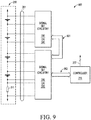
- FIG. 9 illustrates embodiments of the present invention implementing a system 900 whereby two or more of the Signal-Set circuitry 200, 300 may be implemented in order to perform a monitoring of a battery pack 210.
- each of the Signal-Set circuitries 200, 300 are implemented to monitor a certain number of the battery cells within the battery pack 210, with one of the Signal-Set circuitry 200, 300 also monitoring the current within the battery pack 210.
- a signal controller 215 may communicate over the buses 901, 902 with the Signal-Set circuitries 200, 300, including have an ability to address each of the Signal-Set circuitries 200, 300 on an individual addressable basis.
- FIG. 10 illustrates embodiments of the present invention in which a battery pack 210 is utilized within some sort of vehicle 1001 for supplying electric power to an electric motor 1002.
- the electric motor 1002 may be configured to power the vehicle 1001, such as for powering its drive train and/or other accessories.
- a vehicle system controller 1004 may then implement the battery monitoring device disclosed within embodiments of the present invention, which may include a single Signal-Set circuitry 200, 300 coupled to a controller 215, or a battery monitoring system with multiple Signal-Set circuitries 200, 300, such as system 900 illustrated in FIG. 9 .
- a battery monitoring device configured to monitor performance of one or more battery cells including a signal injector configured to produce a replacement physical set that emulates one or more physical properties associated with the one or more battery cells, and a multiplexer configured to selectively output, during different periods of time, the replacement physical set received from the signal injector or a physical set of physical properties received from the one or more battery cells.
- the battery monitoring device may further include a controller configured to compare the physical set to the replacement physical set for a variance outside of a predetermined threshold. The controller may be configured to switch the one or more battery cells into a safe state when the comparison of the physical set to the replacement physical set results in the variance outside of the predetermined threshold.
- the replacement physical set may be predetermined physical quantities that emulate a threshold range of physical properties produced during normal or safe operation of the one or more battery cells.
- the battery monitoring device may further include a sensor circuit configured to separately convert (1) the physical set to a first signal set representing a first digitized measurement of the physical set, and (2) the replacement physical set to a second signal set representing a second digitized measurement of the replacement physical set, wherein the controller compares the first signal set to the second signal set for the variance outside of the predetermined threshold.
- the battery monitoring device may be configured as a single integrated circuit, wherein the sensor circuit is separated from the signal injector and the multiplexer by a common mode failure barrier.
- the signal injector may further include a digital-to-analog converter configured to convert a received digitized voltage set-point value from the controller to thereby output a corresponding analog voltage set-point value, a first amplifier configured to amplify the analog voltage set-point value, and a resistor network configured to produce the replacement physical set emulating one or more voltages of the one or more battery cells as a function of the amplified analog voltage set-point value.
- the signal injector may further include a charge pump configured to power the first amplifier, a second amplifier configured to amplify a first reference voltage for input into the charge pump, and a third amplifier configured to amplify a second reference voltage to power the digital-to-analog converter.
- the resistor network may include a plurality of series-connected resistors configured to receive the amplified analog voltage set-point value to thereby produce a plurality of voltages emulating voltages of the one or more battery cells.
- aspects of the present invention provide a method for monitoring performance of battery cells in a battery pack including converting a physical set of physical properties received from the battery cells to a first signal set representing a first digitized measurement of the physical set, producing a replacement physical set that emulates one or more physical properties associated with the battery cells, converting the replacement physical set to a second signal set representing a second digitized measurement of the replacement physical set, and comparing the first signal set to the second signal set for a variance outside of a predetermined threshold.
- the method may further include, in response to a determination that the comparison of the first signal set to the second signal set results in the variance outside of the predetermined threshold, outputting a switch command suitable to switch the battery cells into a safe state.
- the replacement physical set may be predetermined physical quantities that emulate a threshold range of physical properties produced during normal or safe operation of the battery cells.
- the producing of the replacement physical set may further include converting a received digitized voltage set-point value into a corresponding analog voltage set-point value, amplifying the analog voltage set-point value, and producing with a resistor network the replacement physical set emulating voltages of the battery cells as a function of the amplified analog voltage set-point value.
- the resistor network may include a plurality of series-connected resistors configured to receive the amplified analog voltage set-point value to thereby produce a plurality of voltages emulating voltages of the battery cells.
- a vehicle including an electric motor configured to power the vehicle, a battery pack configured to power the electric motor, and a vehicle system controller configured to control operation of the electric motor and the battery pack, wherein the vehicle system controller includes a battery monitoring device configured to monitor performance of one or more battery cells within the battery pack.
- the battery monitoring device may include a signal injector configured to produce a replacement physical set that emulates one or more physical properties associated with the one or more battery cells, and a multiplexer configured to selectively output, during different periods of time, the replacement physical set received from the signal injector or a physical set of physical properties received from the one or more battery cells.
- the battery monitoring device may further include a sensor circuit configured to (1) convert the physical set to a first signal set representing a first digitized measurement of the physical set, and (2) convert the replacement physical set to a second signal set representing a second digitized measurement of the replacement physical set, and a controller configured to compare the first signal set to the second signal set for the variance outside of the predetermined threshold.
- the controller may be configured to switch the one or more battery cells into a safe state when the comparison of the first signal set representing the first digitized measurement of the physical set to the second signal set representing the second digitized measurement of the replacement physical set results in the variance outside of the predetermined threshold.
- the replacement physical set may be predetermined physical quantities that emulate a threshold range of physical properties produced during normal or safe operation of the one or more battery cells.
- the signal injector may further include a digital-to-analog converter configured to convert a received digitized voltage set-point value from the controller to thereby output a corresponding analog voltage set-point value, a first amplifier configured to amplify the analog voltage set-point value, a resistor network configured to produce the replacement physical set emulating one or more voltages of the one or more battery cells as a function of the amplified analog voltage set-point value, a charge pump configured to power the first amplifier, a second amplifier configured to amplify a first reference voltage for input into the charge pump, and a third amplifier configured to amplify a second reference voltage to power the digital-to-analog converter.
- the resistor network may include a plurality of series-connected resistors configured to receive the amplified analog voltage set-point value to thereby produce a plurality of voltages emulating voltages of the one or more battery cells.
- substantially refers to a degree of deviation that is sufficiently small so as to not measurably detract from the identified property or circumstance.
- the exact degree of deviation allowable may in some cases depend on the specific context.
- the singular forms "a,” “an,” and “the” include plural referents unless the context clearly dictates otherwise.
- the phrase “A, B, C, and/or D” includes A, B, C, and D individually, but also includes any and all combinations and subcombinations of A, B, C, and D.
- These computer program instructions may be provided to a processor of a general purpose computer, special purpose computer, or other programmable data processing apparatus (e.g., the signal set circuitry 200 and/or 300, and the controller 215) to produce a machine, such that the instructions, which execute via the processor of the computer or other programmable data processing apparatus, create means for implementing the functions/acts specified in the flowchart and/or block diagram block or blocks.
- a processor of a general purpose computer, special purpose computer, or other programmable data processing apparatus e.g., the signal set circuitry 200 and/or 300, and the controller 215) to produce a machine, such that the instructions, which execute via the processor of the computer or other programmable data processing apparatus, create means for implementing the functions/acts specified in the flowchart and/or block diagram block or blocks.
- These computer program instructions may also be stored in a computer readable medium that can direct a computer, other programmable data processing apparatus, or other devices to function in a particular manner, such that the instructions stored in the computer readable medium produce an article of manufacture including instructions which implement the function/act specified in the flowchart and/or block diagram block or blocks.
- the computer program instructions may also be loaded onto a computer, other programmable data processing apparatus, or other devices to cause a series of operational steps to be performed on the computer, other programmable apparatus or other devices to produce a computer implemented process such that the instructions which execute on the computer or other programmable apparatus provide processes for implementing the functions/acts specified in the flowchart and/or block diagram block or blocks.
- aspects of the present invention may take the form of an entirely hardware embodiment, an entirely software embodiment (including firmware, resident software, micro-code, etc.) or an embodiment combining software and hardware aspects that may all generally be referred to herein as a "circuit,” “module” or “system.”
- aspects of the present invention may take the form of a computer program product embodied in one or more computer readable medium(s) having computer readable program code embodied thereon.
- the computer readable medium may be a computer readable signal medium or a computer readable storage medium.
- a computer readable storage medium may be, for example, but not limited to, an electronic, magnetic, optical, electromagnetic, infrared, or semiconductor system, apparatus, or device, or any suitable combination of the foregoing.
- a computer readable storage medium may be any tangible medium that can contain, or store a program for use by or in connection with an instruction execution system, apparatus, or device.
- a computer readable signal medium may include a propagated data signal with computer readable program code embodied therein, for example, in baseband or as part of a carrier wave. Such a propagated signal may take any of a variety of forms, including, but not limited to, electro-magnetic, optical, or any suitable combination thereof.
- a computer readable signal medium may be any computer readable medium that is not a computer readable storage medium and that can communicate, propagate, or transport a program for use by or in connection with an instruction execution system, apparatus, or device.
- Program code embodied on a computer readable medium may be transmitted using any appropriate medium, including but not limited to wireless, wireline, optical fiber cable, RF, etc., or any suitable combination of the foregoing.
- Computer program code for carrying out operations for aspects of the present invention may be written in any combination of one or more programming languages, including an object-oriented programming language such as Java, Smalltalk, C++, or the like, and conventional procedural programming languages, such as the "C" programming language or similar programming languages.
- the program code may execute entirely on the user's computer, partly on the user's computer, as a stand-alone software package, partly on the user's computer and partly on a remote computer or entirely on the remote computer or server.
- the remote computer may be connected to the user's computer through any type of network, including a local area network (LAN) or a wide area network (WAN), or the connection may be made to an external computer (for example, through the Internet using an Internet Service Provider).
- LAN local area network
- WAN wide area network
- Internet Service Provider for example, AT&T, MCI, Sprint, EarthLink, MSN, GTE, etc.
Landscapes
- Engineering & Computer Science (AREA)
- Mechanical Engineering (AREA)
- Transportation (AREA)
- General Physics & Mathematics (AREA)
- Physics & Mathematics (AREA)
- Chemical & Material Sciences (AREA)
- Combustion & Propulsion (AREA)
- Life Sciences & Earth Sciences (AREA)
- Sustainable Development (AREA)
- Sustainable Energy (AREA)
- Power Engineering (AREA)
- Automation & Control Theory (AREA)
- Secondary Cells (AREA)
Applications Claiming Priority (1)
| Application Number | Priority Date | Filing Date | Title |
|---|---|---|---|
| US15/157,871 US10106049B2 (en) | 2016-05-18 | 2016-05-18 | Battery monitoring device |
Publications (2)
| Publication Number | Publication Date |
|---|---|
| EP3246719A1 true EP3246719A1 (fr) | 2017-11-22 |
| EP3246719B1 EP3246719B1 (fr) | 2022-12-07 |
Family
ID=58461246
Family Applications (1)
| Application Number | Title | Priority Date | Filing Date |
|---|---|---|---|
| EP17164013.9A Active EP3246719B1 (fr) | 2016-05-18 | 2017-03-30 | Dispositif de surveillance de batterie avec émulateur de batterie |
Country Status (3)
| Country | Link |
|---|---|
| US (1) | US10106049B2 (fr) |
| EP (1) | EP3246719B1 (fr) |
| CN (1) | CN107415725B (fr) |
Cited By (1)
| Publication number | Priority date | Publication date | Assignee | Title |
|---|---|---|---|---|
| TWI861297B (zh) * | 2019-12-04 | 2024-11-11 | 德商羅伯特 博世有限公司 | 用於檢查電池系統的電阻的功能性之方法和裝置,其中電阻充當系統電阻 |
Families Citing this family (7)
| Publication number | Priority date | Publication date | Assignee | Title |
|---|---|---|---|---|
| DE102014214996A1 (de) * | 2014-07-30 | 2016-02-04 | Robert Bosch Gmbh | Verfahren zum Betrieb eines Batteriesystems |
| KR102135996B1 (ko) * | 2016-10-05 | 2020-07-20 | 주식회사 엘지화학 | 배터리 보호 시스템 및 방법 |
| US20190018408A1 (en) * | 2017-07-12 | 2019-01-17 | Qualcomm Incorporated | Systems and methods for verifying integrity of a sensing system |
| US11327121B2 (en) * | 2019-04-03 | 2022-05-10 | Transportation Ip Holdings, Llc | Deviation detection system for energy storage system |
| KR102332444B1 (ko) * | 2019-12-23 | 2021-11-26 | 삼성에스디아이 주식회사 | 열 폭주 검출 장치, 배터리 시스템 및 배터리 시스템의 열 폭주 검출 방법 |
| EP4056402A1 (fr) * | 2021-03-10 | 2022-09-14 | Volvo Truck Corporation | Système de sécurité pour détecter un état critique dans un bloc-batterie |
| CN119147802B (zh) * | 2024-11-19 | 2025-02-14 | 湖南恩智测控技术有限公司 | soc同步控制方法、装置、设备及存储介质 |
Citations (9)
| Publication number | Priority date | Publication date | Assignee | Title |
|---|---|---|---|---|
| EP1993185A2 (fr) * | 2007-05-16 | 2008-11-19 | Hitachi Vehicle Energy, Ltd. | Contrôleur de cellules, module de batterie et système d'alimentation électrique |
| EP2085784A2 (fr) * | 2008-01-29 | 2009-08-05 | Hitachi Ltd. | Système de batterie pour véhicule, module de batterie sur véhicule et contrôleur de cellule |
| CN102944859A (zh) * | 2012-11-23 | 2013-02-27 | 中国科学院电工研究所 | 一种用于电池管理系统的测试装置 |
| DE102012211092A1 (de) * | 2012-06-28 | 2014-01-02 | Robert Bosch Gmbh | Batteriesystem und Kraftfahrzeug mit Batteriesystem |
| US20140129164A1 (en) * | 2012-11-02 | 2014-05-08 | Analog Devices Technology | System and method to reduce data handling on lithium ion battery monitors |
| US20140225622A1 (en) * | 2011-09-08 | 2014-08-14 | Hitachi Vehicle Energy, Ltd. | Battery system monitoring device |
| CN104166057A (zh) * | 2014-08-12 | 2014-11-26 | 山东兴宇新能源科技有限公司 | 一种锂电池保护板测试系统 |
| US20140361743A1 (en) * | 2013-06-11 | 2014-12-11 | Ford Global Technologies, Llc | Detection of Imbalance Across Multiple Battery Cells Measured by the Same Voltage Sensor |
| US20150046108A1 (en) * | 2012-03-13 | 2015-02-12 | Primearth Ev Energy Co., Ltd. | Device and method for estimating secondary cell status |
Family Cites Families (42)
| Publication number | Priority date | Publication date | Assignee | Title |
|---|---|---|---|---|
| US4564798A (en) * | 1982-10-06 | 1986-01-14 | Escutcheon Associates | Battery performance control |
| US5047961A (en) | 1988-05-31 | 1991-09-10 | Simonsen Bent P | Automatic battery monitoring system |
| US5184025A (en) * | 1988-11-14 | 1993-02-02 | Elegant Design Solutions, Inc. | Computer-controlled uninterruptible power supply |
| US5349540A (en) * | 1989-05-12 | 1994-09-20 | Fraunhofer Gesellschaft Zur Foerder Der Angewandten Forschung E. V. | Apparatus for determining the state of physical properties of rechargeable electric energy storage devices |
| US5349535A (en) | 1992-10-20 | 1994-09-20 | Digicomp Research Corporation | Battery condition monitoring and recording system for electric vehicles |
| CN2192014Y (zh) * | 1994-05-03 | 1995-03-15 | 天津华夏科技实业有限公司 | 冷柜、冰箱电子温度控制器 |
| US5781013A (en) | 1994-10-26 | 1998-07-14 | Fuji Jukogyo Kabushiki Kaisha | Battery management system for electric vehicle |
| US5869951A (en) | 1994-10-26 | 1999-02-09 | Fuji Jukogyo Kabushiki Kaisha | Battery management system for electric vehicle |
| US5619417A (en) | 1994-11-23 | 1997-04-08 | Chrysler Corporation | Battery monitoring system for an electric vehicle |
| US5646534A (en) | 1995-01-06 | 1997-07-08 | Chrysler Corporation | Battery monitor for electric vehicles |
| DE19752278A1 (de) * | 1997-11-26 | 1999-06-02 | Bosch Gmbh Robert | Steuerung für ein Kraftfahrzeug mit Fernbedienung oder Transponder |
| DE10394007T5 (de) | 2002-12-31 | 2006-02-02 | Midtronics, Inc., Willowbrook | Vorrichtung und Verfahren zum Vorhersagen der verbleibenden Entladezeit einer Batterie |
| US7317298B1 (en) * | 2003-07-01 | 2008-01-08 | American Power Conversion Corporation | Discharging battery monitoring |
| JP4266358B2 (ja) * | 2004-04-12 | 2009-05-20 | 三菱電機株式会社 | 車載電子制御装置 |
| US7521896B2 (en) * | 2004-07-20 | 2009-04-21 | Panasonic Ev Energy Co., Ltd. | Abnormal voltage detector apparatus for detecting voltage abnormality in assembled battery |
| JP4066381B2 (ja) * | 2005-03-01 | 2008-03-26 | 三菱電機株式会社 | 車載電子制御装置 |
| CN101184994B (zh) * | 2005-04-05 | 2010-11-17 | 能量控制系统工程公司 | 复用器和基于开关的电化学电池监测器以及管理系统和方法 |
| US7349813B2 (en) * | 2006-05-16 | 2008-03-25 | Dresser, Inc. | Fault tolerant power system architecture for fluid flow measurement systems |
| US7612540B2 (en) | 2006-10-24 | 2009-11-03 | Honeywell International Inc. | Lithium-ion battery diagnostic and prognostic techniques |
| JP2009042080A (ja) * | 2007-08-09 | 2009-02-26 | Panasonic Corp | 電圧検出装置 |
| US8564277B2 (en) * | 2009-08-31 | 2013-10-22 | Maxim Integrated Products, Inc. | System for and method of virtual simultaneous sampling with a single ADC core |
| DE102010041492A1 (de) | 2010-09-28 | 2012-03-29 | Robert Bosch Gmbh | Verfahren und Anordnung zur Überwachung mindestens einer Batterie, Batterie mit einer solchen Anordnung sowie ein Kraftfahrzeug mit einer entsprechenden Batterie |
| US9261568B2 (en) * | 2011-02-07 | 2016-02-16 | Analog Devices, Inc. | Diagnostic method to monitor battery cells of safety-critical systems |
| DE102011079291A1 (de) | 2011-07-18 | 2013-01-24 | Sb Limotive Company Ltd. | Batteriemanagementsystem und Verfahren zur Bestimmung der Ladezustände von Batteriezellen, Batterie und Kraftfahrzeug mit Batteriemanagementsystem |
| DE112013000582B4 (de) | 2012-01-16 | 2025-06-05 | Maxim Integrated Products, Inc. | Verfahren und Vorrichtung zur differentiellen Kommunikation |
| US9298867B2 (en) * | 2012-06-22 | 2016-03-29 | GM Global Technology Operations LLC | Modular system and method for simulating performance of an electrical device |
| US8743492B2 (en) * | 2012-07-20 | 2014-06-03 | International Business Machines Corporation | Variable stopwrite threshold with variable smoothing factor |
| WO2014098837A1 (fr) * | 2012-12-19 | 2014-06-26 | Schneider Electric USA, Inc. | Surveillance de profil de tension de batterie pendant le démarrage de générateur |
| US10012702B2 (en) * | 2012-12-19 | 2018-07-03 | Schneider Electric USA, Inc. | Multi-phase power meter configured for monitoring generator battery voltage |
| US9316694B2 (en) * | 2013-02-12 | 2016-04-19 | Johnson Controls Technology Company | Battery monitoring system with time-based diagnostic activation |
| US8901888B1 (en) * | 2013-07-16 | 2014-12-02 | Christopher V. Beckman | Batteries for optimizing output and charge balance with adjustable, exportable and addressable characteristics |
| US9496740B2 (en) * | 2013-06-16 | 2016-11-15 | Chris Beckman | Techniques for optimizing power supply output |
| WO2014191794A1 (fr) | 2013-05-29 | 2014-12-04 | Freescale Semiconductor, Inc. | Appareil de surveillance de cellules, appareil de surveillance de batterie, circuit intégré et procédé permettant de surveiller une cellule rechargeable |
| DE112014002675T5 (de) | 2013-06-04 | 2016-02-18 | Trw Automotive U.S. Llc | Optimierte Spannungsversorgungsarchitektur |
| US9677916B2 (en) * | 2014-07-15 | 2017-06-13 | Palo Alto Research Center Incorporated | Energy system monitoring |
| US9312837B2 (en) * | 2014-08-05 | 2016-04-12 | Apple Inc. | Dynamic margin tuning for controlling custom circuits and memories |
| US10247783B2 (en) * | 2014-09-23 | 2019-04-02 | Ford Global Technologies, Llc | Sensor system for measuring battery internal state |
| US9843069B2 (en) * | 2014-09-26 | 2017-12-12 | Ford Global Technologies, Llc | Battery capacity degradation resolution methods and systems |
| KR102356475B1 (ko) * | 2015-02-06 | 2022-01-27 | 삼성전자주식회사 | 배터리의 충전 전압 데이터에 기반한 배터리 상태 추정 방법 및 장치 |
| US10153521B2 (en) * | 2015-08-06 | 2018-12-11 | Powin Energy Corporation | Systems and methods for detecting a battery pack having an operating issue or defect |
| US10330732B2 (en) * | 2015-10-01 | 2019-06-25 | California Institute Of Technology | Systems and methods for monitoring characteristics of energy units |
| CN108432081A (zh) * | 2015-12-31 | 2018-08-21 | 深圳市大疆创新科技有限公司 | 用于管理电池组件的方法和系统 |
-
2016
- 2016-05-18 US US15/157,871 patent/US10106049B2/en active Active
-
2017
- 2017-03-30 EP EP17164013.9A patent/EP3246719B1/fr active Active
- 2017-05-10 CN CN201710327809.9A patent/CN107415725B/zh active Active
Patent Citations (9)
| Publication number | Priority date | Publication date | Assignee | Title |
|---|---|---|---|---|
| EP1993185A2 (fr) * | 2007-05-16 | 2008-11-19 | Hitachi Vehicle Energy, Ltd. | Contrôleur de cellules, module de batterie et système d'alimentation électrique |
| EP2085784A2 (fr) * | 2008-01-29 | 2009-08-05 | Hitachi Ltd. | Système de batterie pour véhicule, module de batterie sur véhicule et contrôleur de cellule |
| US20140225622A1 (en) * | 2011-09-08 | 2014-08-14 | Hitachi Vehicle Energy, Ltd. | Battery system monitoring device |
| US20150046108A1 (en) * | 2012-03-13 | 2015-02-12 | Primearth Ev Energy Co., Ltd. | Device and method for estimating secondary cell status |
| DE102012211092A1 (de) * | 2012-06-28 | 2014-01-02 | Robert Bosch Gmbh | Batteriesystem und Kraftfahrzeug mit Batteriesystem |
| US20140129164A1 (en) * | 2012-11-02 | 2014-05-08 | Analog Devices Technology | System and method to reduce data handling on lithium ion battery monitors |
| CN102944859A (zh) * | 2012-11-23 | 2013-02-27 | 中国科学院电工研究所 | 一种用于电池管理系统的测试装置 |
| US20140361743A1 (en) * | 2013-06-11 | 2014-12-11 | Ford Global Technologies, Llc | Detection of Imbalance Across Multiple Battery Cells Measured by the Same Voltage Sensor |
| CN104166057A (zh) * | 2014-08-12 | 2014-11-26 | 山东兴宇新能源科技有限公司 | 一种锂电池保护板测试系统 |
Cited By (1)
| Publication number | Priority date | Publication date | Assignee | Title |
|---|---|---|---|---|
| TWI861297B (zh) * | 2019-12-04 | 2024-11-11 | 德商羅伯特 博世有限公司 | 用於檢查電池系統的電阻的功能性之方法和裝置,其中電阻充當系統電阻 |
Also Published As
| Publication number | Publication date |
|---|---|
| CN107415725A (zh) | 2017-12-01 |
| EP3246719B1 (fr) | 2022-12-07 |
| CN107415725B (zh) | 2022-10-28 |
| US10106049B2 (en) | 2018-10-23 |
| US20170334306A1 (en) | 2017-11-23 |
Similar Documents
| Publication | Publication Date | Title |
|---|---|---|
| EP3246719B1 (fr) | Dispositif de surveillance de batterie avec émulateur de batterie | |
| JP7471337B2 (ja) | 直列接続電池セルのための監視システム | |
| KR102684737B1 (ko) | Bms 평가 장치 및 이를 이용한 bms 평가 방법 | |
| EP3443636B1 (fr) | Procédé et système d'équilibrage de cellule | |
| JP6628956B2 (ja) | バッテリモジュールシステム | |
| EP3317683B1 (fr) | Appareil de mesure d'impédance de cellule de stockage d'énergie, procédés et systèmes associés | |
| US20100217552A1 (en) | Battery Management System for Measuring Remaining Charges in a Battery Packet with Multi-Cells | |
| KR20130094703A (ko) | 대형 배터리 시스템을 위한 동적으로 재구성가능한 프레임워크 | |
| CN1794001A (zh) | 通过测量输入充电电压来检验智能电池故障的方法及相关系统 | |
| US11480626B1 (en) | Systems and method for testing battery management systems | |
| CN104335440A (zh) | 确定多串式逆变器中的串结构 | |
| Hu | Battery management system for electric vehicle applications | |
| Vitols | Design of an embedded battery management system with passive balancing | |
| Lai et al. | A quantitative method for early-stage detection of the internal-short-circuit in Lithium-ion battery pack under float-charging conditions | |
| WO2016106968A1 (fr) | Batterie et procédé et système d'apprentissage de correction automatique de capacité pour batterie | |
| KR101036037B1 (ko) | 이차 전지 | |
| Dorn et al. | Battery management system | |
| CN112701362A (zh) | 涉及电池单元测量的系统和方法 | |
| CN107516916A (zh) | 电池组或电容器组管理系统及其控制方法 | |
| JP5897941B2 (ja) | 2次電池の充放電検査装置 | |
| Shah et al. | Platform software development for battery management system in electric vehicle | |
| CN114270203B (zh) | 电池组模拟装置及使用其检查电池管理单元的方法 | |
| KR102761622B1 (ko) | 배터리 전류 측정 장치 및 방법과, 배터리 팩 | |
| KR20210080650A (ko) | 배터리의 안전 상태 제시를 위한 배터리의 고장 상태 알고리즘 | |
| US20260126496A1 (en) | Device for diagnosing a state of a battery and method thereof |
Legal Events
| Date | Code | Title | Description |
|---|---|---|---|
| PUAI | Public reference made under article 153(3) epc to a published international application that has entered the european phase |
Free format text: ORIGINAL CODE: 0009012 |
|
| STAA | Information on the status of an ep patent application or granted ep patent |
Free format text: STATUS: THE APPLICATION HAS BEEN PUBLISHED |
|
| AK | Designated contracting states |
Kind code of ref document: A1 Designated state(s): AL AT BE BG CH CY CZ DE DK EE ES FI FR GB GR HR HU IE IS IT LI LT LU LV MC MK MT NL NO PL PT RO RS SE SI SK SM TR |
|
| AX | Request for extension of the european patent |
Extension state: BA ME |
|
| STAA | Information on the status of an ep patent application or granted ep patent |
Free format text: STATUS: REQUEST FOR EXAMINATION WAS MADE |
|
| 17P | Request for examination filed |
Effective date: 20180522 |
|
| RBV | Designated contracting states (corrected) |
Designated state(s): AL AT BE BG CH CY CZ DE DK EE ES FI FR GB GR HR HU IE IS IT LI LT LU LV MC MK MT NL NO PL PT RO RS SE SI SK SM TR |
|
| STAA | Information on the status of an ep patent application or granted ep patent |
Free format text: STATUS: EXAMINATION IS IN PROGRESS |
|
| 17Q | First examination report despatched |
Effective date: 20191205 |
|
| RIC1 | Information provided on ipc code assigned before grant |
Ipc: G01R 19/165 20060101ALN20220615BHEP Ipc: B60L 58/15 20190101ALI20220615BHEP Ipc: G01R 31/396 20190101ALI20220615BHEP Ipc: G01R 31/36 20060101AFI20220615BHEP |
|
| RIC1 | Information provided on ipc code assigned before grant |
Ipc: G01R 19/165 20060101ALN20220621BHEP Ipc: B60L 58/15 20190101ALI20220621BHEP Ipc: G01R 31/396 20190101ALI20220621BHEP Ipc: G01R 31/36 20060101AFI20220621BHEP |
|
| GRAP | Despatch of communication of intention to grant a patent |
Free format text: ORIGINAL CODE: EPIDOSNIGR1 |
|
| STAA | Information on the status of an ep patent application or granted ep patent |
Free format text: STATUS: GRANT OF PATENT IS INTENDED |
|
| RIC1 | Information provided on ipc code assigned before grant |
Ipc: G01R 19/165 20060101ALN20220701BHEP Ipc: B60L 58/15 20190101ALI20220701BHEP Ipc: G01R 31/396 20190101ALI20220701BHEP Ipc: G01R 31/36 20060101AFI20220701BHEP |
|
| RIC1 | Information provided on ipc code assigned before grant |
Ipc: G01R 19/165 20060101ALN20220721BHEP Ipc: B60L 58/15 20190101ALI20220721BHEP Ipc: G01R 31/396 20190101ALI20220721BHEP Ipc: G01R 31/36 20060101AFI20220721BHEP |
|
| INTG | Intention to grant announced |
Effective date: 20220803 |
|
| GRAS | Grant fee paid |
Free format text: ORIGINAL CODE: EPIDOSNIGR3 |
|
| GRAA | (expected) grant |
Free format text: ORIGINAL CODE: 0009210 |
|
| STAA | Information on the status of an ep patent application or granted ep patent |
Free format text: STATUS: THE PATENT HAS BEEN GRANTED |
|
| AK | Designated contracting states |
Kind code of ref document: B1 Designated state(s): AL AT BE BG CH CY CZ DE DK EE ES FI FR GB GR HR HU IE IS IT LI LT LU LV MC MK MT NL NO PL PT RO RS SE SI SK SM TR |
|
| REG | Reference to a national code |
Ref country code: GB Ref legal event code: FG4D |
|
| REG | Reference to a national code |
Ref country code: CH Ref legal event code: EP Ref country code: AT Ref legal event code: REF Ref document number: 1536609 Country of ref document: AT Kind code of ref document: T Effective date: 20221215 |
|
| REG | Reference to a national code |
Ref country code: DE Ref legal event code: R096 Ref document number: 602017064313 Country of ref document: DE |
|
| REG | Reference to a national code |
Ref country code: IE Ref legal event code: FG4D |
|
| REG | Reference to a national code |
Ref country code: LT Ref legal event code: MG9D |
|
| REG | Reference to a national code |
Ref country code: NL Ref legal event code: MP Effective date: 20221207 |
|
| PG25 | Lapsed in a contracting state [announced via postgrant information from national office to epo] |
Ref country code: SE Free format text: LAPSE BECAUSE OF FAILURE TO SUBMIT A TRANSLATION OF THE DESCRIPTION OR TO PAY THE FEE WITHIN THE PRESCRIBED TIME-LIMIT Effective date: 20221207 Ref country code: NO Free format text: LAPSE BECAUSE OF FAILURE TO SUBMIT A TRANSLATION OF THE DESCRIPTION OR TO PAY THE FEE WITHIN THE PRESCRIBED TIME-LIMIT Effective date: 20230307 Ref country code: LT Free format text: LAPSE BECAUSE OF FAILURE TO SUBMIT A TRANSLATION OF THE DESCRIPTION OR TO PAY THE FEE WITHIN THE PRESCRIBED TIME-LIMIT Effective date: 20221207 Ref country code: FI Free format text: LAPSE BECAUSE OF FAILURE TO SUBMIT A TRANSLATION OF THE DESCRIPTION OR TO PAY THE FEE WITHIN THE PRESCRIBED TIME-LIMIT Effective date: 20221207 Ref country code: ES Free format text: LAPSE BECAUSE OF FAILURE TO SUBMIT A TRANSLATION OF THE DESCRIPTION OR TO PAY THE FEE WITHIN THE PRESCRIBED TIME-LIMIT Effective date: 20221207 |
|
| REG | Reference to a national code |
Ref country code: AT Ref legal event code: MK05 Ref document number: 1536609 Country of ref document: AT Kind code of ref document: T Effective date: 20221207 |
|
| PG25 | Lapsed in a contracting state [announced via postgrant information from national office to epo] |
Ref country code: RS Free format text: LAPSE BECAUSE OF FAILURE TO SUBMIT A TRANSLATION OF THE DESCRIPTION OR TO PAY THE FEE WITHIN THE PRESCRIBED TIME-LIMIT Effective date: 20221207 Ref country code: PL Free format text: LAPSE BECAUSE OF FAILURE TO SUBMIT A TRANSLATION OF THE DESCRIPTION OR TO PAY THE FEE WITHIN THE PRESCRIBED TIME-LIMIT Effective date: 20221207 Ref country code: LV Free format text: LAPSE BECAUSE OF FAILURE TO SUBMIT A TRANSLATION OF THE DESCRIPTION OR TO PAY THE FEE WITHIN THE PRESCRIBED TIME-LIMIT Effective date: 20221207 Ref country code: HR Free format text: LAPSE BECAUSE OF FAILURE TO SUBMIT A TRANSLATION OF THE DESCRIPTION OR TO PAY THE FEE WITHIN THE PRESCRIBED TIME-LIMIT Effective date: 20221207 Ref country code: GR Free format text: LAPSE BECAUSE OF FAILURE TO SUBMIT A TRANSLATION OF THE DESCRIPTION OR TO PAY THE FEE WITHIN THE PRESCRIBED TIME-LIMIT Effective date: 20230308 |
|
| PG25 | Lapsed in a contracting state [announced via postgrant information from national office to epo] |
Ref country code: NL Free format text: LAPSE BECAUSE OF FAILURE TO SUBMIT A TRANSLATION OF THE DESCRIPTION OR TO PAY THE FEE WITHIN THE PRESCRIBED TIME-LIMIT Effective date: 20221207 |
|
| PG25 | Lapsed in a contracting state [announced via postgrant information from national office to epo] |
Ref country code: SM Free format text: LAPSE BECAUSE OF FAILURE TO SUBMIT A TRANSLATION OF THE DESCRIPTION OR TO PAY THE FEE WITHIN THE PRESCRIBED TIME-LIMIT Effective date: 20221207 Ref country code: RO Free format text: LAPSE BECAUSE OF FAILURE TO SUBMIT A TRANSLATION OF THE DESCRIPTION OR TO PAY THE FEE WITHIN THE PRESCRIBED TIME-LIMIT Effective date: 20221207 Ref country code: PT Free format text: LAPSE BECAUSE OF FAILURE TO SUBMIT A TRANSLATION OF THE DESCRIPTION OR TO PAY THE FEE WITHIN THE PRESCRIBED TIME-LIMIT Effective date: 20230410 Ref country code: EE Free format text: LAPSE BECAUSE OF FAILURE TO SUBMIT A TRANSLATION OF THE DESCRIPTION OR TO PAY THE FEE WITHIN THE PRESCRIBED TIME-LIMIT Effective date: 20221207 Ref country code: CZ Free format text: LAPSE BECAUSE OF FAILURE TO SUBMIT A TRANSLATION OF THE DESCRIPTION OR TO PAY THE FEE WITHIN THE PRESCRIBED TIME-LIMIT Effective date: 20221207 Ref country code: AT Free format text: LAPSE BECAUSE OF FAILURE TO SUBMIT A TRANSLATION OF THE DESCRIPTION OR TO PAY THE FEE WITHIN THE PRESCRIBED TIME-LIMIT Effective date: 20221207 |
|
| P01 | Opt-out of the competence of the unified patent court (upc) registered |
Effective date: 20230725 |
|
| PG25 | Lapsed in a contracting state [announced via postgrant information from national office to epo] |
Ref country code: SK Free format text: LAPSE BECAUSE OF FAILURE TO SUBMIT A TRANSLATION OF THE DESCRIPTION OR TO PAY THE FEE WITHIN THE PRESCRIBED TIME-LIMIT Effective date: 20221207 Ref country code: IS Free format text: LAPSE BECAUSE OF FAILURE TO SUBMIT A TRANSLATION OF THE DESCRIPTION OR TO PAY THE FEE WITHIN THE PRESCRIBED TIME-LIMIT Effective date: 20230407 Ref country code: AL Free format text: LAPSE BECAUSE OF FAILURE TO SUBMIT A TRANSLATION OF THE DESCRIPTION OR TO PAY THE FEE WITHIN THE PRESCRIBED TIME-LIMIT Effective date: 20221207 |
|
| REG | Reference to a national code |
Ref country code: DE Ref legal event code: R097 Ref document number: 602017064313 Country of ref document: DE |
|
| PLBE | No opposition filed within time limit |
Free format text: ORIGINAL CODE: 0009261 |
|
| STAA | Information on the status of an ep patent application or granted ep patent |
Free format text: STATUS: NO OPPOSITION FILED WITHIN TIME LIMIT |
|
| PG25 | Lapsed in a contracting state [announced via postgrant information from national office to epo] |
Ref country code: MC Free format text: LAPSE BECAUSE OF FAILURE TO SUBMIT A TRANSLATION OF THE DESCRIPTION OR TO PAY THE FEE WITHIN THE PRESCRIBED TIME-LIMIT Effective date: 20221207 Ref country code: DK Free format text: LAPSE BECAUSE OF FAILURE TO SUBMIT A TRANSLATION OF THE DESCRIPTION OR TO PAY THE FEE WITHIN THE PRESCRIBED TIME-LIMIT Effective date: 20221207 |
|
| REG | Reference to a national code |
Ref country code: CH Ref legal event code: PL |
|
| 26N | No opposition filed |
Effective date: 20230908 |
|
| GBPC | Gb: european patent ceased through non-payment of renewal fee |
Effective date: 20230330 |
|
| PG25 | Lapsed in a contracting state [announced via postgrant information from national office to epo] |
Ref country code: SI Free format text: LAPSE BECAUSE OF FAILURE TO SUBMIT A TRANSLATION OF THE DESCRIPTION OR TO PAY THE FEE WITHIN THE PRESCRIBED TIME-LIMIT Effective date: 20221207 |
|
| REG | Reference to a national code |
Ref country code: BE Ref legal event code: MM Effective date: 20230331 |
|
| PG25 | Lapsed in a contracting state [announced via postgrant information from national office to epo] |
Ref country code: LU Free format text: LAPSE BECAUSE OF NON-PAYMENT OF DUE FEES Effective date: 20230330 |
|
| REG | Reference to a national code |
Ref country code: IE Ref legal event code: MM4A |
|
| PG25 | Lapsed in a contracting state [announced via postgrant information from national office to epo] |
Ref country code: GB Free format text: LAPSE BECAUSE OF NON-PAYMENT OF DUE FEES Effective date: 20230330 |
|
| PG25 | Lapsed in a contracting state [announced via postgrant information from national office to epo] |
Ref country code: LI Free format text: LAPSE BECAUSE OF NON-PAYMENT OF DUE FEES Effective date: 20230331 Ref country code: IE Free format text: LAPSE BECAUSE OF NON-PAYMENT OF DUE FEES Effective date: 20230330 Ref country code: GB Free format text: LAPSE BECAUSE OF NON-PAYMENT OF DUE FEES Effective date: 20230330 Ref country code: CH Free format text: LAPSE BECAUSE OF NON-PAYMENT OF DUE FEES Effective date: 20230331 |
|
| PG25 | Lapsed in a contracting state [announced via postgrant information from national office to epo] |
Ref country code: BE Free format text: LAPSE BECAUSE OF NON-PAYMENT OF DUE FEES Effective date: 20230331 |
|
| PG25 | Lapsed in a contracting state [announced via postgrant information from national office to epo] |
Ref country code: IT Free format text: LAPSE BECAUSE OF FAILURE TO SUBMIT A TRANSLATION OF THE DESCRIPTION OR TO PAY THE FEE WITHIN THE PRESCRIBED TIME-LIMIT Effective date: 20221207 |
|
| PG25 | Lapsed in a contracting state [announced via postgrant information from national office to epo] |
Ref country code: BG Free format text: LAPSE BECAUSE OF FAILURE TO SUBMIT A TRANSLATION OF THE DESCRIPTION OR TO PAY THE FEE WITHIN THE PRESCRIBED TIME-LIMIT Effective date: 20221207 |
|
| PG25 | Lapsed in a contracting state [announced via postgrant information from national office to epo] |
Ref country code: BG Free format text: LAPSE BECAUSE OF FAILURE TO SUBMIT A TRANSLATION OF THE DESCRIPTION OR TO PAY THE FEE WITHIN THE PRESCRIBED TIME-LIMIT Effective date: 20221207 |
|
| PG25 | Lapsed in a contracting state [announced via postgrant information from national office to epo] |
Ref country code: CY Free format text: LAPSE BECAUSE OF FAILURE TO SUBMIT A TRANSLATION OF THE DESCRIPTION OR TO PAY THE FEE WITHIN THE PRESCRIBED TIME-LIMIT; INVALID AB INITIO Effective date: 20170330 |
|
| PG25 | Lapsed in a contracting state [announced via postgrant information from national office to epo] |
Ref country code: HU Free format text: LAPSE BECAUSE OF FAILURE TO SUBMIT A TRANSLATION OF THE DESCRIPTION OR TO PAY THE FEE WITHIN THE PRESCRIBED TIME-LIMIT; INVALID AB INITIO Effective date: 20170330 |
|
| PG25 | Lapsed in a contracting state [announced via postgrant information from national office to epo] |
Ref country code: TR Free format text: LAPSE BECAUSE OF FAILURE TO SUBMIT A TRANSLATION OF THE DESCRIPTION OR TO PAY THE FEE WITHIN THE PRESCRIBED TIME-LIMIT Effective date: 20221207 |
|
| PGFP | Annual fee paid to national office [announced via postgrant information from national office to epo] |
Ref country code: DE Payment date: 20260219 Year of fee payment: 10 |
|
| PGFP | Annual fee paid to national office [announced via postgrant information from national office to epo] |
Ref country code: FR Payment date: 20260219 Year of fee payment: 10 |