EP3246846B1 - Kommunikationssystem, leistungsversorgungssystem, das ein solches kommunikationssystem umfasst, und entsprechendes verfahren - Google Patents
Kommunikationssystem, leistungsversorgungssystem, das ein solches kommunikationssystem umfasst, und entsprechendes verfahren Download PDFInfo
- Publication number
- EP3246846B1 EP3246846B1 EP17290079.7A EP17290079A EP3246846B1 EP 3246846 B1 EP3246846 B1 EP 3246846B1 EP 17290079 A EP17290079 A EP 17290079A EP 3246846 B1 EP3246846 B1 EP 3246846B1
- Authority
- EP
- European Patent Office
- Prior art keywords
- communication
- contactless
- contactless medium
- medium
- communication device
- Prior art date
- Legal status (The legal status is an assumption and is not a legal conclusion. Google has not performed a legal analysis and makes no representation as to the accuracy of the status listed.)
- Active
Links
Images


Classifications
-
- G—PHYSICS
- G06—COMPUTING OR CALCULATING; COUNTING
- G06K—GRAPHICAL DATA READING; PRESENTATION OF DATA; RECORD CARRIERS; HANDLING RECORD CARRIERS
- G06K7/00—Methods or arrangements for sensing record carriers, e.g. for reading patterns
- G06K7/10—Methods or arrangements for sensing record carriers, e.g. for reading patterns by electromagnetic radiation, e.g. optical sensing; by corpuscular radiation
- G06K7/10009—Methods or arrangements for sensing record carriers, e.g. for reading patterns by electromagnetic radiation, e.g. optical sensing; by corpuscular radiation sensing by radiation using wavelengths larger than 0.1 mm, e.g. radio-waves or microwaves
- G06K7/10019—Methods or arrangements for sensing record carriers, e.g. for reading patterns by electromagnetic radiation, e.g. optical sensing; by corpuscular radiation sensing by radiation using wavelengths larger than 0.1 mm, e.g. radio-waves or microwaves resolving collision on the communication channels between simultaneously or concurrently interrogated record carriers.
- G06K7/10079—Methods or arrangements for sensing record carriers, e.g. for reading patterns by electromagnetic radiation, e.g. optical sensing; by corpuscular radiation sensing by radiation using wavelengths larger than 0.1 mm, e.g. radio-waves or microwaves resolving collision on the communication channels between simultaneously or concurrently interrogated record carriers. the collision being resolved in the spatial domain, e.g. temporary shields for blindfolding the interrogator in specific directions
- G06K7/10089—Methods or arrangements for sensing record carriers, e.g. for reading patterns by electromagnetic radiation, e.g. optical sensing; by corpuscular radiation sensing by radiation using wavelengths larger than 0.1 mm, e.g. radio-waves or microwaves resolving collision on the communication channels between simultaneously or concurrently interrogated record carriers. the collision being resolved in the spatial domain, e.g. temporary shields for blindfolding the interrogator in specific directions the interrogation device using at least one directional antenna or directional interrogation field to resolve the collision
-
- G—PHYSICS
- G06—COMPUTING OR CALCULATING; COUNTING
- G06K—GRAPHICAL DATA READING; PRESENTATION OF DATA; RECORD CARRIERS; HANDLING RECORD CARRIERS
- G06K7/00—Methods or arrangements for sensing record carriers, e.g. for reading patterns
- G06K7/10—Methods or arrangements for sensing record carriers, e.g. for reading patterns by electromagnetic radiation, e.g. optical sensing; by corpuscular radiation
- G06K7/10009—Methods or arrangements for sensing record carriers, e.g. for reading patterns by electromagnetic radiation, e.g. optical sensing; by corpuscular radiation sensing by radiation using wavelengths larger than 0.1 mm, e.g. radio-waves or microwaves
- G06K7/10316—Methods or arrangements for sensing record carriers, e.g. for reading patterns by electromagnetic radiation, e.g. optical sensing; by corpuscular radiation sensing by radiation using wavelengths larger than 0.1 mm, e.g. radio-waves or microwaves using at least one antenna particularly designed for interrogating the wireless record carriers
- G06K7/10356—Methods or arrangements for sensing record carriers, e.g. for reading patterns by electromagnetic radiation, e.g. optical sensing; by corpuscular radiation sensing by radiation using wavelengths larger than 0.1 mm, e.g. radio-waves or microwaves using at least one antenna particularly designed for interrogating the wireless record carriers using a plurality of antennas, e.g. configurations including means to resolve interference between the plurality of antennas
-
- G—PHYSICS
- G06—COMPUTING OR CALCULATING; COUNTING
- G06K—GRAPHICAL DATA READING; PRESENTATION OF DATA; RECORD CARRIERS; HANDLING RECORD CARRIERS
- G06K7/00—Methods or arrangements for sensing record carriers, e.g. for reading patterns
- G06K7/10—Methods or arrangements for sensing record carriers, e.g. for reading patterns by electromagnetic radiation, e.g. optical sensing; by corpuscular radiation
- G06K7/10009—Methods or arrangements for sensing record carriers, e.g. for reading patterns by electromagnetic radiation, e.g. optical sensing; by corpuscular radiation sensing by radiation using wavelengths larger than 0.1 mm, e.g. radio-waves or microwaves
- G06K7/10366—Methods or arrangements for sensing record carriers, e.g. for reading patterns by electromagnetic radiation, e.g. optical sensing; by corpuscular radiation sensing by radiation using wavelengths larger than 0.1 mm, e.g. radio-waves or microwaves the interrogation device being adapted for miscellaneous applications
- G06K7/10475—Methods or arrangements for sensing record carriers, e.g. for reading patterns by electromagnetic radiation, e.g. optical sensing; by corpuscular radiation sensing by radiation using wavelengths larger than 0.1 mm, e.g. radio-waves or microwaves the interrogation device being adapted for miscellaneous applications arrangements to facilitate interaction with further interrogation devices, e.g. such that at least two interrogation devices may function and cooperate in a network of such devices
Definitions
- the present invention relates to a communication system with at least one contactless medium, the communication system being of the type comprising a first communication device adapted to read data on a first non-contact medium and a second communication device adapted to read data. data on a second contactless medium,
- the invention also relates to a service provisioning system comprising such a communication system, and an associated communication method.
- the document EP 1 605 391 describes a set of antennas for an RFID reader operating at distinct carrier frequencies.
- a communication system comprising two communication devices for reading each of the data on a contactless medium.
- a first communication device is configured to read data on a contactless identification medium to identify the user
- the second communication device is configured to read data on a payment medium in order to pay a payment for the identified user.
- the same contactless media can serve both as an identification medium and a payment medium.
- Each communication device comprises an antenna (or loop) generating an electromagnetic field to allow communication between the communication device and the respective contactless medium when said contactless medium is placed in a region, referred to as a "communication region" where the Electromagnetic field has sufficient intensity.
- the antennas are physically spaced from one another so as to avoid any overlap of the communication regions.
- each user In order to identify and possibly pay for the service, this input and / or output of the service as appropriate, each user must thus successively present the identification medium in the first communication region associated with the first communication device then the contactless payment medium in the second communication region associated with the second device.
- the purpose of the invention is therefore to improve the ergonomics of systems employing two non-contact communication devices.
- the subject of the invention is an assembly comprising a communication system and at least one non-contact medium according to claim 1.
- the assembly also has one or more of the features according to claims 2 to 5.
- the invention also relates to a service delivery system according to claim 6.
- the service delivery system also has one or more of the features of claims 7 to 9.
- the invention also relates to a communication method according to claim 10.
- the communication method also has one or more of the features according to claims 11 to 12.
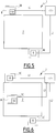
- the service delivery system 1, shown on the figure 1 is intended to provide a service requiring the identification of a service user.
- this service delivery system 1 is, as shown, constituted by a system for controlling access to a reserved area 2, for which the identification of the users to be able to determine whether they have a right of access. access to enter and / or leave the reserved area 2 and, if necessary, to determine the amount that the user must pay in order to benefit from this right of access.
- Reserved area 2 is typically a parking lot.
- the reserved zone 2 is a road network, for example a motorway network.
- the access control system 1 thus comprises an input terminal 3A, disposed at an input of the reserved zone 2, and an output terminal 4A disposed at an output of the reserved zone 2.
- the input terminal 3A comprises an identifier 6 for reading a unique identifier (described below) of a first contactless medium 12 ( Figure 2 ), and the output terminal 4A comprises a service payment system 8 with a communication system 10 for communicating with the first contactless medium 12 ( Figure 2 ) and, through this, allow the identification of the user and the payment of the service.
- the identifier 6 is connected by an L1 data link to a server 11 and the service payment system 8 is connected by an L2 data link to the server 11.
- the server 11 is for example a management server reserved area 2.
- the server 11 is then configured to create and manage user accounts each associated with a unique identifier (described below).
- contactless media is meant a medium carrying data transferable by electromagnetic waves to suitable communication systems.
- data recorded on the first non-contact medium 12 is readable by inductive coupling.
- the first contactless medium 12 is a contactless payment card, or a mobile phone capable of near-field communication (CCP or NFC).
- the first non-contact medium 12 comprises an integrated circuit (not shown) comprising a memory and an antenna.
- the first contactless medium 12 is in accordance with the ISO 14443 standard defining requirements for contactless media, such as physical characteristics of the first non-contact media 12, the radio frequency power and a transmission protocol.
- the communication system 10 comprises a title management device 14, a payment unit 16 and an external controller 18.
- the title management device 14 is connected to the external controller 18 via a connection 20 and the payment unit 16 is connected to the external controller 18 by a connection 22.
- the title management device 14 is capable of identifying the first contactless medium 12.
- identifying is meant obtaining a unique identifier associated with the first contactless medium 12.
- the unique identifier makes it possible to identify without For example, in the case where the first contactless medium 12 is a payment card, the unique identifier is the primary account number (or PAN of the English "Primary Account Number"). saved on the map. Obtaining this unique identifier makes it possible to identify the user by retrieving the data of a user account associated with this unique identifier or the creation of a user account during a first obtaining of the identifier concerned.
- the title management device 14 comprises a first communication device 24 and a first data processing unit 26.
- the first communication device 24 is able to establish a communication with the first non-contact medium 12.
- the first device communication 24 is also suitable for establishing a communication with a contactless smart card which is not necessarily a payment card, for example a membership card or a transport card, a badge, or a parking ticket without contact that is distributed at the entrance of the reserved area 2, for example a so-called "radio-tag" chip according to the RFID principle (of the English "Radio Frequency Identification").
- the first communication device 24 comprises a first coupler 28 and a first antenna 30.
- the first data processing unit 26 and the first coupler 28 are connected by a connection 33 to the first antenna 30.
- the first data processing unit 26 is formed for example of a memory and a processor associated with the memory, not shown.
- the first data processing unit 26 is configured to process information received from the first antenna 30.
- the information received is, for example, information relating to the identification of the first contactless medium 12.
- the first antenna 30 is, for example, a loop antenna, preferably made in printed circuit. It is able to convert an electrical signal into a high-frequency magnetic field (13.56 MHz +/- 7 kHz in the case of ISO 14443) that can be modulated to transmit information to the media. In the opposite direction, the media is read by load modulation.
- the first antenna 30 has a round shape or a loop shape. In a variant, the first antenna 30 has a rectangular shape.
- the first antenna 30 is disposed in a protective envelope, not shown.
- a first communication region 34 is defined with the first non-contact medium 12 such that, when the first non-contact medium 12 is in the first communication region 34, the first communication device 24 is adapted to communicating with the first contactless medium 12, that is to say, at least, reading data recorded on the first contactless medium 12 and, preferably, transmitting to the first contactless medium 12 electromagnetic signals carriers of information.
- the first communication region 34 has a volume defined by the first antenna 30.
- the first communication region 34 corresponds in particular to a volume in which an electromagnetic field generated during a reading of data on the first contactless medium 12 by the first antenna 30 has a power greater than a threshold value.
- the volume of the first communication region 34 is a function of the characteristics of the first antenna 30, the first non-contact medium 12 and propagation medium, that is to say air between the first antenna 30 and the first contactless medium 12.
- the first communication region 34 is represented by a hatching.
- the first communication region 34 is delimited externally by the first antenna 30.
- the first communication region 34 is delimited by a communication distance between a point between the first antenna 30 and the first contactless medium 12 A typical value of the communication distance is 3 cm.
- the first communication region 34 has a cylindrical or barrel-shaped volume.
- the first coupler 28 is configured to receive electrical signals from the first antenna 30 and to convert them into interpretable data by the first data processing unit 26.
- the first coupler comprises a processor implementing the common communication standards.
- non-contact such as ISO / IEC 14443-2, ISO / IEC 14443-3 and ISO / IEC 14443-4 ("Identification cards - Contactless integrated circuit (s) cards - Proximity cards - Part 2: Radio frequency interface and communication signals "," - Part 3: initialization and anti-collision "and” - Part 4: transmission protocol ", so as to allow the detection of the first non-contact medium 12, the transfer of energy initiating the dialogue and exchanging information with the first contactless medium 12 via the first antenna 30.
- the first coupler 28 is clean, when activated, to control the first antenna 30 so that it emits a field for detecting the approach of a contactless medium.
- the first coupler 28 is also clean, when the presence of a non-contact medium in the first communication region 34 has been detected, to control the first antenna 30 so that it successively emits several electromagnetic signals each using a protocol communication device corresponding to one of the existing contactless communication protocols, in other words, so that the first antenna 30 performs a polling (or "polling" in English), while waiting for a response of the detected contactless media .
- the first coupler 28 is still clean, when a response from the contactless medium has been received, to fix the last protocol used as a communication protocol with said contactless medium, and to exchange data with the contactless medium using this protocol. Communication.
- the identifier 6 of the input terminal 3A typically has the same characteristics as the title management device 14 described above.
- the title management device 6 has the following characteristic: first data processing unit 26 is able to communicate the unique identifier associated with the first contactless medium 12 to the management server 11, as well as the time and date of presentation of said first contactless medium 12 to the input terminal 3A.
- the payment unit 16 is able to authorize and make a payment using the first contactless medium 12.
- payments is meant here the technical steps that are required to make a payment of a product or service by payment using a payment into a bank account.
- payments means the transmission of technical data, such as the primary account number or other technical or computer data, from the first contactless medium 12, via the payment unit 16, to a dedicated computer server, for example in a bank.
- the payment unit 16 complies with the EMVCo EMVCo requirements, including the requirements listed in the book. D, version 2.6, of these specifications.
- the payment unit 16 also complies with payment security provisions such as the protection of data against fraudulent use set up by the banks.
- the payment unit 16 comprises a second communication device 36 and a second data processing unit 38.
- the second communication device 36 is able to establish a communication with the first contactless medium 12.
- the second communication device 36 comprises a second coupler 40 and a second antenna 42.
- the second data processing unit 38 and the second coupler 40 are connected by a connection 46 to the second antenna 42.
- the second data processing unit 38 is formed for example of a memory and a processor associated with the memory, not shown.
- the second data processing unit 38 is configured to process information received from the second antenna 42.
- the information received is, for example, information relating to the payment by the first contactless medium 12, such as a user's bank account number.
- the data processing unit 38 is configured to generate data to be sent by the second communication device 36.
- the second antenna 42 is, for example, a loop antenna, preferably made in printed circuit. It is suitable for converting an electrical signal into a field Magnetic high frequency (13.56 MHz +/- 7 kHz in the case of ISO 14443) flexible to transmit information to the media. In the opposite direction, the media is read by load modulation.
- the second antenna 42 has a round shape or a loop shape. In a variant, the second antenna 42 has a rectangular shape.
- the second antenna 42 is disposed in a protective casing (not shown) with the second data processing unit 38 and the second coupler 40.
- a communication region 48 is defined with the first contactless medium 12.
- the second antenna 42 is able to communicate with the first medium contactless 12, that is to say to exchange with the first contactless media 12 electromagnetic signals including messages relating to payment.
- the second communication region 48 has a volume defined by the second antenna 42.
- the second communication region 48 corresponds in particular to a volume in which an electromagnetic field generated during a read / write of data on the first contactless medium 12 by the second antenna 42 has a power greater than a threshold value.
- the volume of the second communication region 48 is a function of the characteristics of the second antenna 42, the first non-contact medium 12 and the propagation medium, that is to say the air between the second antenna 42 and the second antenna 42. first contactless media 12.
- the second communication region 48 is represented by a hatching.
- the second communication region 48 is delimited externally by the second antenna 42.
- the second communication region 48 is delimited by a communication distance between a point between the second antenna 42 and the first contactless medium 12 A typical value of the communication distance is 3 cm.
- the second communication region 48 has a cylindrical volume.
- the second communication region 48 and the first communication region 34 overlap.
- the first and second communication regions 34, 48 include an overlap region 50 belonging to both the first communication region 34 and the second communication region 48.
- the first antenna 30 and the second antenna 42 are arranged concentrically with respect to each other.
- the first antenna 30 and the second antenna 42 comprise the same center.
- the first antenna 30 is arranged concentrically around the second antenna 42.
- the second communication region 48 is then entirely comprised in the first communication region 34, i.e. the second communication region 48 constitutes a part of the first communication region 34.
- the overlap 50 is then merged with the second communication region 48.
- the first antenna 30 is arranged next to the second antenna 42.
- the first and second communication regions 34, 48 defined by the electromagnetic field of the first and second antenna 30, 42 respectively, overlap, in this variant not shown, only in a fraction of the volume of the first communication region 34 and the second communication region 48. In other words, only part of the second communication region 48 is included in the first region
- the overlap region 50 is then formed by said portion of the second communication region 48 included in the first communication region 34.
- the communication system 10 comprises a presentation area of the first contactless medium 12, materialized on a surface (not shown) of the communication system 10 visible to the user, said presentation area corresponding to the intersection of the area overlap 50 with said visible surface.
- the second coupler 40 is configured to receive electrical signals from the second antenna 42 and to convert them into interpretable data by the second data processing unit 38.
- the second coupler 40 comprises a processor implementing the common standards of contactless communication, such as ISO / IEC 14443-2, ISO / IEC 14443-3 and ISO / IEC 14443-4 ("Identification cards - Contactless integrated circuit (s) cards - Proximity cards - Part 2: Radio Frequency Interface and Communication Signals "," - Part 3: Initialization and Anti-collision "and” - Part 4: Transmission Protocol ", to permit the selection and decoding of radio waves picked up by the second antenna 42.
- ISO / IEC 14443-2 ISO / IEC 14443-3
- ISO / IEC 14443-4 ISO / IEC 14443-4
- the second coupler is also configured to update the first contactless media 12 information about the payment.
- the second coupler 40 is configured to encrypt or decrypt the messages of a communication with the first contactless medium 12.
- the second coupler 40 is clean, when it is activated and the presence of a first non-contact medium 12 in the second communication region 48 has been detected, to control the second antenna 42 so that it emits successively several electromagnetic signals each using a own communication corresponding to one of the existing contactless communication protocols, in other words, so that the second antenna 42 performs a polling (or "polling" in English), waiting for a response of the contactless contact detected.
- the second coupler 40 is also clean when a response from the contactless medium has been received, to fix the last protocol used as a communication protocol with said contactless medium, and to exchange data with the contactless medium using this protocol. Communication.
- the external controller 18 of the data communication system 10 is configured to selectively activate the first and second communication devices 24, 36.
- activate is meant to send to the first communication device 24, respectively to the second communication device 36, an activation instruction such that, upon receipt of this instruction, said communication device 24, 36 emits an electromagnetic field of communication with the first contactless medium 12.
- activate means providing a power supply to the communication device 24, 36 concerned.
- selective activate is meant that the activation instruction or the power supply is each time exclusive to either the first communication device 24 or the second communication device 36, so that never more than one of the communication devices 24, 36 is activated at a time.
- the other communication device 24, 36, which is then not activated, is thus unable to read data on the first contactless medium 12 and no electromagnetic field is generated by the antenna of this communication device 24 , 36 not activated.
- Activating separately the first and second communication devices 24, 36 makes it possible to avoid interference of the electromagnetic field generated by the first antenna 30 with the electromagnetic field generated by the second antenna 42.
- the external controller 18 is distinct from the first communication device 24 and the second communication device 36. In addition, the external controller 18 is disposed externally with respect to the title management device 14 and with respect to the control unit 14. payment 16.
- a method 100 of operation of the service delivery system 1 will now be described, with reference to the figure 3 .
- the method 100 includes a first phase 110 for managing an entry in the reserved zone 2, followed by a phase 120 for managing an output outside the reserved zone 2.
- Phase 110 includes a step 130 for activating identifier 6, followed by a step 140 of identification, then a step 150 of creation of a user account, before finally a step 160 of authorization of access.
- a user wishing to access the parking 2 has a first contactless medium 12 at the input terminal 3A. More specifically, the user presents the first contactless medium 12 in the first communication region 34 of the identifier 6 of the input terminal 3A.
- a presence detector (not shown) detects the presence of the first non-contact medium 12 and activates the identifier 6.
- the identification step 140 comprises a substep 142 of active waiting for detection of the first contactless medium 12, followed by a substep 144 of user data transmission.
- the first antenna 30 successively emits several electromagnetic signals each using a proper communication protocol corresponding to one of the existing contactless communication protocols.
- the first antenna 30 performs a polling (or "polling" in English) to detect a response of the first contactless medium 12.
- the first antenna 30 transmits a signal using a communication protocol implemented by the service subscription cards before issuing a signal using a communication protocol implemented by the bank cards.
- the identifier 6 receives a response from the first contactless medium 12 and sets the last protocol used as the communication protocol with the first contactless medium 12.
- the identifier 6 exchanges data with the first non-contact medium 12 so as to retrieve identification information from the first non-contact medium 12, for example, PAN.
- the first communication device 24 of the identifier 6 establishes a communication with the first contactless medium 12, using the communication protocol set in the previous sub-step 142. Then, when an electromagnetic signal is received by the first antenna 30, a corresponding electrical signal is produced by the first antenna 30 and transferred by the connection 33 to the first coupler 28, which first coupler 28 selects and decodes this signal before transferring the data thus extracted from the data processing unit 26.
- the data processing unit 26 processes the received data and thus identifies the first contactless medium 12.
- the received data comprise, for example, the unique identifier of the first contactless medium 12.
- the identification step 140 is implemented several times, as indicated by the arrow I on the figure 3 . For example, during an identification failure, said step 140 is repeated.
- step 150 of creation of a user account at least some of the received data is transferred by the data link L1 to the server 11.
- the server 11 then creates a user account associated with the received data, that is to say say, typically to the unique identifier of the first contactless medium 12, then it records said account in a memory of the server 11.
- step 160 of access authorization access to the reserved zone 2 is authorized.
- an entry barrier (not shown) opens. The user can then bring his vehicle into the car park.
- the server 11 records the date and time of entry of the user in the parking in the user account.
- the vehicle When leaving the car park, the vehicle is moved to the output terminal 4A. It is then that the output management phase 120 begins.
- Phase 120 includes a first activation step 170, followed by an identification step 180, before a step 190 of searching for the associated user account, then a step 200 of determining a time spent in the reserved zone 2, a step 210 for calculating a payment amount, a first signaling step 215, a second activation step 220, a payment step 230, a second signaling step 240, a third activation step 250, a step 260 of payment, and finally a step 270 of exit authorization.
- the output terminal 4A detects the presence of the vehicle. A message is transmitted to the external controller 18, which in response activates the title management device 14. The identification step 180 can then begin.
- the identification step 180 typically has the same characteristics as the identification step 140 described above. Therefore, the identification step 180 comprises a substep 182 corresponding to the substep 142 of the active waiting detection of the first contactless medium 12, and the following sub-step 184 corresponding to the substep 144 of user data transmission.
- the unique identifier is transmitted by the data link L2 to the server 11, which searches for the user account associated with the unique identifier stored in the server memory 11. From of the date of the time of entry into the reserved zone 2, recorded in the user account, and the date of the current time, the server 11 determines, during the step 200, a time spent in the zone 2. Depending on the time spent in the area reserved 2 and applicable parking rates, the server 11 finally determines, in step 210, the amount of a payment to be made by the user.
- the external controller 18 is informed of the execution of the first communication step 180. More specifically, the title management device 14 sends a message to the external controller 18, said message signaling to the controller external 18 that the first communication step 180 is completed. The external controller 18 then deactivates the title management device 14.
- the external controller 18 activates the payment unit 16.
- the payment step 230 can then begin.
- the payment step 230 includes a sub-step 232 of active waiting detection of the first contactless media 12 and a sub-step 234 of user data transmission.
- the second antenna 42 successively emits several electromagnetic signals, each using a specific communication protocol corresponding to one of the existing contactless communication protocols.
- the second antenna 42 performs a polling (or "polling" in English) to detect a response of the first contactless medium 12.
- the second antenna 42 transmits a signal using a communication protocol implemented by bank cards.
- the second antenna 42 transmits a signal using a communication protocol that allows contactless payment according to the rules mentioned above.
- the unit payment 16 receives a response from the first contactless medium 12 and sets the last protocol used as the communication protocol with the first contactless medium 12.
- the payment unit 16 exchanges data with the first contactless medium 12 so as to retrieve information relating to a payment by the first contactless medium 12, for example the PAN.
- the second communication device 36 of the payment unit 16 establishes a communication with the first contactless medium 12, using the communication protocol set in the preceding substep 232.
- the communication comprises data received from the first contactless medium 12 and data sent to the first contactless medium 12.
- an electromagnetic signal is received by the second antenna 42
- a corresponding electrical signal is produced by the second antenna 42 and transferred by the connection 46 to second coupler 40.
- the second coupler 40 selects and decodes this signal before transferring the data thus extracted to the data processing unit 38.
- data is transferred from the data processing unit 38 to the second coupler 28 which encodes data into signals.
- the signals are, in the form of a modulation of the high frequency magnetic field, emitted by the second antenna 42 to the first contactless medium 12.
- These signals are typically used by the first contactless medium 12 to evolve its own corresponding technical data. for example the number of payments made by the first contactless medium 12, the amount of payments made by the first contactless medium 12, the payment limits, the rules that will condition the need for a connection, for example via the Internet with a bank or rules that define the possibility of making a payment without connection with the bank.
- the payment step 230 is implemented several times, as indicated by the symbol I on the figure 3 . For example, upon a denial of payment in payment step 230, said step 230 is repeated.
- the external controller 18 is informed of the execution of the payment step 230. More specifically, the payment unit 16 sends a message to the external controller 18, said message signaling to the external controller 18 that the payment step 230 is completed. The external controller 18 then deactivates the payment unit 16.
- the external controller 18 reactivates the title management device 14.
- the acknowledgment step 260 can then begin.
- Acknowledgment step 260 includes an active waiting sub-step 262 for detecting the first contactless medium 12, followed by a substep 264 for transmitting user data.
- the detection active sub-step 262 typically has the same characteristics as the detecting active wait sub-step 142 described above.
- a marking on the contactless medium 12 is recorded, which confirms the payment made during the payment step 230.
- the acknowledgment step 260 is implemented several times, as indicated by the symbol I on the figure 3 . For example, during an acknowledgment failure, said step 260 is repeated.
- the exit from the reserved zone 2 is authorized.
- an exit barrier of the parking (not shown) opens. The user's vehicle can then leave the car park.
- the y-axis of the figure 4 represents the intensity C of an electromagnetic field during a period of time t. If the intensity C has the value 1, the magnetic field is generated, and if the intensity C has the value 0, the magnetic field is not generated.
- the intensity C of two electromagnetic fields over time is represented. By a continuous line, the intensity C of a first electromagnetic field EM1 generated by the first antenna 30 of the title management device 14 is represented, and by a discontinuous line, the intensity C of a second electromagnetic field EM2 generated by the second antenna 42 of the payment unit is shown.
- the active waiting sub-step 182 is performed and between the time t2 and t3, the transmission sub-step 184 is performed.
- the active waiting sub-step 232 is performed and between the time t5 and t6, the transmission sub-step 234 is performed.
- the first electromagnetic field EM1 is generated again.
- This period corresponds to the payment clearing step 260, between the times t7 and t8, the active waiting sub-step 262 and, between the times t8 and t9, the transmission sub-step 264.
- the duration of the period between t0 and t9 is less than 1 s.
- the duration is 0.8 s.
- the communication system 10 can perform both the identification and the payment without the user has to move the first contactless media 12.
- the user will thus perform a single action for the implementation of the entire method described, namely to present the first contactless medium 12 in the second communication region 48 This simplifies the ergonomics of the use of the communication system 10.
- the use is easier to understand by the user.
- the invention makes it possible to avoid having to distribute paper tickets at the entrance to the reserved area since it is directly a medium already owned by the user that serves as an identification token. This reduces the risk of loss or damage to the ticket and reduces the consumption of consumables for the operator of the access control system.
- the contactless medium presented to the second communication device 36 is constituted by a second non-contact medium different from the first non-contact medium.
- the second contactless medium must, in this variant, be constituted by a payment card or a mobile phone capable of near-field communication (CCP or NFC)
- the first medium without contact can be constituted by a contactless smart card which is not necessarily a payment card, for example a membership card or a transport card, a badge, or a contactless parking ticket which is distributed in entry of the reserved zone 2, for example a so-called "radio-tag" chip according to the RFID (Radio Frequency Identification) principle.
- the service payment system 8 instead of being integrated into an output terminal, is integrated in an input terminal 3B of the access control system 1.
- This variant is particularly suitable for cases where the reserved area 2 is for example a public transport network, a cinema, a swimming pool, an amusement park, a zoological park, a museum, a monument, a historic site or a fixed-price car park.
- the access control system 1 comprises an output terminal 4B of reserved area 2 equipped with identifier 6.
- the service payment system 8 is integrated neither in an input terminal nor in an output terminal of the access control system 1, but in a separate equipment 5C connected by an L3 data link to the server 11
- the access control system 1 comprises, in this variant, an input terminal 3C and an output terminal 4C each equipped with the identifier 6.
- the service payment system 8 may be a service control and payment terminal, typically in a fast food restaurant.
- the title management device 14 may be able to register in a memory of the first contactless medium 12, after the payment step 110, one or more title (s) giving right to the (x) service (s) ) bought.
Landscapes
- Engineering & Computer Science (AREA)
- Physics & Mathematics (AREA)
- Health & Medical Sciences (AREA)
- Toxicology (AREA)
- General Health & Medical Sciences (AREA)
- Electromagnetism (AREA)
- Artificial Intelligence (AREA)
- Computer Vision & Pattern Recognition (AREA)
- General Physics & Mathematics (AREA)
- Theoretical Computer Science (AREA)
- Computer Networks & Wireless Communication (AREA)
- Near-Field Transmission Systems (AREA)
- Devices For Checking Fares Or Tickets At Control Points (AREA)
- Mobile Radio Communication Systems (AREA)
Claims (12)
- Anordnung aufweisend ein Kommunikationssystem (10) und mindestens ein kontaktloses Medium (12), wobei das Kommunikationssystem (10) eine erste Kommunikationsvorrichtung (24), die zum Lesen von Daten auf dem kontaktlosen Medium (12) eingerichtet ist, und eine zweite Kommunikationsvorrichtung (36) aufweist, die zum Lesen von Daten auf dem kontaktlosen Medium eingerichtet ist, wobei die erste Kommunikationsvorrichtung (24) einen ersten Koppler (28) und eine erste Antenne (30) aufweist, die einen ersten Kommunikationsbereich (34) mit dem kontaktlosen Medium (12) definiert, derart, dass, wenn das kontaktlose Medium (12) in dem ersten Kommunikationsbereich (34) platziert ist, die erste Kommunikationsvorrichtung (24) eine Kommunikation mit dem kontaktlosen Medium (12) herstellen kann, und die zweite Kommunikationsvorrichtung (36) einen zweiten Koppler (40) und eine zweite Antenne (42) aufweist, die einen zweiten Kommunikationsbereich (48) mit dem kontaktlosen Medium derart definiert, dass wenn das kontaktlose Medium (12) in dem zweiten Kommunikationsbereich (48) platziert ist, die zweite Kommunikationsvorrichtung (36) eine Kommunikation mit dem kontaktlosen Medium (12) herstellen kann, wobei sich der erste und der zweite Kommunikationsbereich (34, 48) überlappen,
wobei das Kommunikationssystem (10) eine externe Steuerung (18) aufweist, die von der ersten und zweiten Kommunikationsvorrichtung (24, 36) verschieden ist und konfiguriert ist, die erste und zweite Kommunikationsvorrichtung (24, 36) selektiv zu aktivieren,
charakterisiert
dadurch, dass jede der ersten und zweiten Antenne (30, 42) dazu eingerichtet ist, ein elektrisches Signal in ein modulierbares Hochfrequenzmagnetfeld umzuwandeln, um Informationen an das kontaktlose Medium zu übermitteln (12),
und dadurch, dass
das kontaktlose Medium (12) durch eine kontaktlose Bezahlkarte oder ein Mobiltelefon gebildet wird, das zur Nahfeldkommunikation eingerichtet ist, und die zweite Kommunikationsvorrichtung (36) zu einer kontaktlosen Bezahleinheit gehört. - Anordnung nach Anspruch 1, wobei die erste Antenne (30) konzentrisch um die zweite Antenne (42) herum angeordnet ist.
- Anordnung nach Anspruch 1 oder 2, wobei der zweite Kommunikationsbereich (48) in dem ersten Kommunikationsbereich (34) enthalten ist.
- Anordnung nach einem der Ansprüche 1 bis 3, wobei die zweite Kommunikationsvorrichtung (36) ferner eingerichtet ist, Daten auf das kontaktlose Medium (12) zu schreiben.
- Anordnung nach einem der Ansprüche 1 bis 4, wobei die erste Kommunikationsvorrichtung (24) eingerichtet ist, eine eindeutige Kennung des kontaktlosen Mediums (12) zu beschaffen.
- Dienstbereitstellungssystem (1), aufweisend das Kommunikationssystem (10) nach einem der Ansprüche 1 bis 5.
- Dienstbereitstellungssystem (1) nach Anspruch 6, wobei das Dienstbereitstellungssystem (1) aus einem Zugangskontrollsystem (2) für einen reservierten Bereich gebildet ist, wobei das Zugangskontrollsystem mindestens einen Eingangspfosten (3A), der an einem Eingang des reservierten Bereichs (2) angeordnet ist, und mindestens einen Ausgangspfosten (4A), der an einem Ausgang des reservierten Bereichs (2) angeordnet ist, aufweist,
wobei der Eingangspfosten (3A) einen Identifikator (6) zum Lesen einer eindeutigen Kennung des kontaktlosen Mediums (12) aufweist und der Ausgangspfosten (4A) das Kommunikationssystem (10) aufweist. - Dienstbereitstellungssystem (1) nach Anspruch 6, wobei das Dienstbereitstellungssystem (1) aus einem Zugangskontrollsystem (2) für einen reservierten Bereiche gebildet ist, wobei das Zugangskontrollsystem mindestens einen Eingangspfosten (3B), der an einem Eingang des reservierten Bereichs (2) angeordnet ist, und mindestens einen Ausgangspfosten (4B), der an einem Ausgang des reservierten Bereichs (2) angeordnet ist aufweist, wobei der Eingangspfosten (3B) das Kommunikationssystem (10) aufweist und der Ausgangspfosten (4B) einen Identifikator (6) zum Lesen einer eindeutigen Kennung des kontaktlosen Mediums (12) aufweist.
- Dienstbereitstellungssystem (1) nach Anspruch 6, wobei das Dienstbereitstellungssystem (1) aus einem Zugangskontrollsystem (2) für einen reservierten Bereich gebildet ist, wobei das Zugangskontrollsystem mindestens einen Eingangspfosten (3C), der an einem Eingang des reservierten Bereichs (2) angeordnet ist, und mindestens einen Ausgangspfosten (4C), der an einem Ausgang des reservierten Bereichs (2) angeordnet ist, und mindestens ein separates Gerät (5C) aufweist, das von dem Eingangspfosten (3C) und dem Ausgangspfosten (4C) verschieden ist,
wobei der Eingangspfosten (3C) einen Identifikator (6) zum Lesen einer eindeutigen Kennung des kontaktlosen Mediums (12) aufweist, wobei der Ausgangspfosten (4C) auch einen Identifikator (6) zum Lesen einer eindeutigen Kennung des kontaktlosen Mediums (12) aufweist und das separate Gerät (5C) das Kommunikationssystem (10) aufweist. - Verfahren (120) zum Kommunizieren mit mindestens einem kontaktlosen Medium (12), das eine integrierte Schaltung mit einem Speicher und einer Kontaktloses-Medium-Antenne aufweist, wobei das Verfahren (120) aufweist:einen Schritt des Präsentierens des kontaktlosen Mediums (12),einen ersten Schritt (180) des Kommunizierens mit dem kontaktlosen Medium (12), wobei der erste Kommunikationsschritt (180) durch eine erste Kommunikationsvorrichtung (24) durchgeführt wird, die einen ersten Koppler (28) und eine erste Antenne (30) aufweist, die einen ersten Kommunikationsbereich (34) mit dem kontaktlosen Medium definiert (12) derart, dass, wenn das kontaktlose Medium (12) in dem ersten Kommunikationsbereich (34) platziert ist, die erste Kommunikationsvorrichtung (24) eine Kommunikation mit dem kontaktlosen Medium (12) herstellen kann, undeinen zweiten Kommunikationsschritt (230) mit dem kontaktlosen Medium, wobei der zweite Kommunikationsschritt (230) durch eine zweite Kommunikationsvorrichtung (36) durchgeführt wird, die einen zweiten Koppler (40) und eine zweite Antenne (42) aufweist, die einen zweiten Kommunikationsbereich (48) mit dem kontaktlosen Medium definiert derart, dass, wenn das kontaktlose Medium in dem zweiten Kommunikationsbereich (48) platziert ist, die zweite Kommunikationsvorrichtung (36) eine Kommunikation mit dem kontaktlosen Medium herstellen kann, wobei der erste und der zweite Kommunikationsbereich (34, 48) einen Überlappungsbereich (50) aufweisen, der sowohl zum ersten Kommunikationsbereich (34) als auch zum zweiten Kommunikationsbereich (48) gehört,wobei der erste Kommunikationsschritt (180) und der zweite Kommunikationsschritt (230) von einer externen Steuerung (18) ausgelöst werden, die von der ersten und der zweiten Kommunikationsvorrichtung (24, 36) verschieden ist, wobei die externe Steuerung (18) nacheinander die erste Kommunikationsvorrichtung (24) und dann die zweite Kommunikationsvorrichtung (36) aktiviert,charakterisiertdadurch, dass jede der ersten und zweiten Antenne (30, 42) dazu eingerichtet ist, ein elektrisches Signal in ein modulierbares Hochfrequenzmagnetfeld umzuwandeln, um Informationen an das kontaktlose Medium zu übermitteln (12),und dadurch, dassdas kontaktlose Medium (12) durch eine kontaktlose Bezahlkarte oder ein Mobiltelefon gebildet wird, das zur Nahfeldkommunikation eingerichtet ist, und die zweite Kommunikationsvorrichtung (36) zu einer kontaktlosen Bezahleinheit gehört.
- Verfahren (120) nach Anspruch 10, aufweisend einen Signalisierungsschritt (215), wobei die externe Steuerung (18) über die Ausführung des ersten Kommunikationsschritts (180) informiert wird, gefolgt von einem Aktivierungsschritt (220), bei dem die externe Steuerung (18) die zweite Kommunikationsvorrichtung (36) zum Ausführen des zweiten Kommunikationsschritts (230) aktiviert.
- Verfahren (120) nach Anspruch 10 oder 11, wobei in dem Präsentationsschritt das kontaktlose Medium (12) in dem Überlappungsbereich (50) angeordnet wird, wobei das kontaktlose Medium (12) in diesem Überlappungsbereich (50) während der ersten und zweiten Kommunikationsphase in diesem Bereich verbleibt.
Priority Applications (5)
| Application Number | Priority Date | Filing Date | Title |
|---|---|---|---|
| PL17290079T PL3246846T3 (pl) | 2017-06-19 | 2017-06-19 | System komunikacyjny, system świadczenia usług obejmujący taki system komunikacyjny i powiązany sposób |
| EP17290079.7A EP3246846B1 (de) | 2017-06-19 | 2017-06-19 | Kommunikationssystem, leistungsversorgungssystem, das ein solches kommunikationssystem umfasst, und entsprechendes verfahren |
| ES17290079T ES2760999T3 (es) | 2017-06-19 | 2017-06-19 | Sistema de comunicación, sistema de prestación de servicios que comprende un tal sistema de comunicación, y procedimiento asociado |
| MX2018007285A MX378156B (es) | 2017-06-19 | 2018-06-14 | Sistema de comunicacion, sistema de prestacion de servicio que comprende un sistema de comunicacion, y proceso asociado. |
| CA3008731A CA3008731A1 (fr) | 2017-06-19 | 2018-06-15 | Systeme de communication, systeme de fourniture de service comprenant un tel systeme de communication, et procede associe |
Applications Claiming Priority (1)
| Application Number | Priority Date | Filing Date | Title |
|---|---|---|---|
| EP17290079.7A EP3246846B1 (de) | 2017-06-19 | 2017-06-19 | Kommunikationssystem, leistungsversorgungssystem, das ein solches kommunikationssystem umfasst, und entsprechendes verfahren |
Publications (3)
| Publication Number | Publication Date |
|---|---|
| EP3246846A2 EP3246846A2 (de) | 2017-11-22 |
| EP3246846A3 EP3246846A3 (de) | 2018-02-14 |
| EP3246846B1 true EP3246846B1 (de) | 2019-09-18 |
Family
ID=59298414
Family Applications (1)
| Application Number | Title | Priority Date | Filing Date |
|---|---|---|---|
| EP17290079.7A Active EP3246846B1 (de) | 2017-06-19 | 2017-06-19 | Kommunikationssystem, leistungsversorgungssystem, das ein solches kommunikationssystem umfasst, und entsprechendes verfahren |
Country Status (5)
| Country | Link |
|---|---|
| EP (1) | EP3246846B1 (de) |
| CA (1) | CA3008731A1 (de) |
| ES (1) | ES2760999T3 (de) |
| MX (1) | MX378156B (de) |
| PL (1) | PL3246846T3 (de) |
Family Cites Families (2)
| Publication number | Priority date | Publication date | Assignee | Title |
|---|---|---|---|---|
| US7439862B2 (en) * | 2004-05-18 | 2008-10-21 | Assa Abloy Ab | Antenna array for an RFID reader compatible with transponders operating at different carrier frequencies |
| US7511620B2 (en) * | 2006-03-31 | 2009-03-31 | Symbol Technologies, Inc. | Methods and apparatus for antenna failover in an RFID system with multi-antenna zones |
-
2017
- 2017-06-19 PL PL17290079T patent/PL3246846T3/pl unknown
- 2017-06-19 EP EP17290079.7A patent/EP3246846B1/de active Active
- 2017-06-19 ES ES17290079T patent/ES2760999T3/es active Active
-
2018
- 2018-06-14 MX MX2018007285A patent/MX378156B/es unknown
- 2018-06-15 CA CA3008731A patent/CA3008731A1/fr active Pending
Non-Patent Citations (1)
| Title |
|---|
| None * |
Also Published As
| Publication number | Publication date |
|---|---|
| EP3246846A3 (de) | 2018-02-14 |
| PL3246846T3 (pl) | 2020-06-15 |
| CA3008731A1 (fr) | 2018-12-19 |
| ES2760999T3 (es) | 2020-05-18 |
| EP3246846A2 (de) | 2017-11-22 |
| MX378156B (es) | 2025-03-10 |
| MX2018007285A (es) | 2019-02-08 |
Similar Documents
| Publication | Publication Date | Title |
|---|---|---|
| US10380849B2 (en) | Payment processing with automatic no-touch mode selection | |
| Curran et al. | Near field communication | |
| US8233841B2 (en) | Near field communication initialization | |
| TWI498838B (zh) | 銷售點系統及完成交易的方法 | |
| KR101757421B1 (ko) | 원-클릭 오프라인 구매 | |
| US10346827B2 (en) | Display of a transaction history using a payment card display device for secure transaction processing | |
| CN101107615A (zh) | 具有近场通信(nfc)的安全信用卡 | |
| TW201301161A (zh) | 移動裝置、授權交易支付的方法及傳送交易支付的方法 | |
| EP2865112B1 (de) | Authentifizierungsmethode zwischen einem mobilen endgerät und einer station | |
| EP2177922A1 (de) | Prüfverfahren eines elektronischen Identitätsdokuments und entsprechende Vorrichtung | |
| EP3246846B1 (de) | Kommunikationssystem, leistungsversorgungssystem, das ein solches kommunikationssystem umfasst, und entsprechendes verfahren | |
| CA3116316A1 (en) | Proximity electronic credit exchange system and method therefor | |
| EP1794896B1 (de) | Kontaktlose datenschutzvorrichtung | |
| EP1988498A2 (de) | Verfahren und System zum Austausch von Daten, die einem Benutzer vorbehalten sind | |
| HK1247378A (en) | Communication system, service provision system comprising such a communication system, and associated method | |
| HK1247378B (zh) | 通信系统,包括这种通信系统的服务提供系统及相关方法 | |
| HK1247378A1 (en) | Communication system, service provision system comprising such a communication system, and associated method | |
| EP1214686A1 (de) | Tragbares elektronisches gerät mit einer anzeigevorrichtung und mittel zum laden von nachrichten dafür | |
| EP2938007A1 (de) | Verfahren zur steuerung einer gesamtheit von miteinander kommunizierenden objekten, das die ausbreitung eines signals, insbesondere eines wecksignals, zwischen diesen objekten ermöglicht | |
| FR2976385A1 (fr) | Procede pour definir une transaction a effectuer au moyen d'un serveur | |
| FR2899706A1 (fr) | Procede de reponse adaptative par authentification a une requete d'action |
Legal Events
| Date | Code | Title | Description |
|---|---|---|---|
| PUAI | Public reference made under article 153(3) epc to a published international application that has entered the european phase |
Free format text: ORIGINAL CODE: 0009012 |
|
| STAA | Information on the status of an ep patent application or granted ep patent |
Free format text: STATUS: THE APPLICATION HAS BEEN PUBLISHED |
|
| AK | Designated contracting states |
Kind code of ref document: A2 Designated state(s): AL AT BE BG CH CY CZ DE DK EE ES FI FR GB GR HR HU IE IS IT LI LT LU LV MC MK MT NL NO PL PT RO RS SE SI SK SM TR |
|
| AX | Request for extension of the european patent |
Extension state: BA ME |
|
| PUAL | Search report despatched |
Free format text: ORIGINAL CODE: 0009013 |
|
| AK | Designated contracting states |
Kind code of ref document: A3 Designated state(s): AL AT BE BG CH CY CZ DE DK EE ES FI FR GB GR HR HU IE IS IT LI LT LU LV MC MK MT NL NO PL PT RO RS SE SI SK SM TR |
|
| AX | Request for extension of the european patent |
Extension state: BA ME |
|
| RIC1 | Information provided on ipc code assigned before grant |
Ipc: G06K 7/10 20060101AFI20180105BHEP |
|
| STAA | Information on the status of an ep patent application or granted ep patent |
Free format text: STATUS: REQUEST FOR EXAMINATION WAS MADE |
|
| 17P | Request for examination filed |
Effective date: 20180306 |
|
| RAP1 | Party data changed (applicant data changed or rights of an application transferred) |
Owner name: REVENUE COLLECTION SYSTEMS FRANCE SAS |
|
| STAA | Information on the status of an ep patent application or granted ep patent |
Free format text: STATUS: EXAMINATION IS IN PROGRESS |
|
| 17Q | First examination report despatched |
Effective date: 20180531 |
|
| RBV | Designated contracting states (corrected) |
Designated state(s): AL AT BE BG CH CY CZ DE DK EE ES FI FR GB GR HR HU IE IS IT LI LT LU LV MC MK MT NL NO PL PT RO RS SE SI SK SM TR |
|
| REG | Reference to a national code |
Ref country code: HK Ref legal event code: DE Ref document number: 1247378 Country of ref document: HK |
|
| GRAP | Despatch of communication of intention to grant a patent |
Free format text: ORIGINAL CODE: EPIDOSNIGR1 |
|
| STAA | Information on the status of an ep patent application or granted ep patent |
Free format text: STATUS: GRANT OF PATENT IS INTENDED |
|
| INTG | Intention to grant announced |
Effective date: 20190423 |
|
| GRAS | Grant fee paid |
Free format text: ORIGINAL CODE: EPIDOSNIGR3 |
|
| GRAA | (expected) grant |
Free format text: ORIGINAL CODE: 0009210 |
|
| STAA | Information on the status of an ep patent application or granted ep patent |
Free format text: STATUS: THE PATENT HAS BEEN GRANTED |
|
| AK | Designated contracting states |
Kind code of ref document: B1 Designated state(s): AL AT BE BG CH CY CZ DE DK EE ES FI FR GB GR HR HU IE IS IT LI LT LU LV MC MK MT NL NO PL PT RO RS SE SI SK SM TR |
|
| REG | Reference to a national code |
Ref country code: GB Ref legal event code: FG4D Free format text: NOT ENGLISH |
|
| REG | Reference to a national code |
Ref country code: CH Ref legal event code: EP |
|
| REG | Reference to a national code |
Ref country code: DE Ref legal event code: R096 Ref document number: 602017007170 Country of ref document: DE |
|
| REG | Reference to a national code |
Ref country code: AT Ref legal event code: REF Ref document number: 1182178 Country of ref document: AT Kind code of ref document: T Effective date: 20191015 |
|
| REG | Reference to a national code |
Ref country code: IE Ref legal event code: FG4D Free format text: LANGUAGE OF EP DOCUMENT: FRENCH |
|
| REG | Reference to a national code |
Ref country code: NL Ref legal event code: MP Effective date: 20190918 |
|
| PG25 | Lapsed in a contracting state [announced via postgrant information from national office to epo] |
Ref country code: SE Free format text: LAPSE BECAUSE OF FAILURE TO SUBMIT A TRANSLATION OF THE DESCRIPTION OR TO PAY THE FEE WITHIN THE PRESCRIBED TIME-LIMIT Effective date: 20190918 Ref country code: NO Free format text: LAPSE BECAUSE OF FAILURE TO SUBMIT A TRANSLATION OF THE DESCRIPTION OR TO PAY THE FEE WITHIN THE PRESCRIBED TIME-LIMIT Effective date: 20191218 Ref country code: BG Free format text: LAPSE BECAUSE OF FAILURE TO SUBMIT A TRANSLATION OF THE DESCRIPTION OR TO PAY THE FEE WITHIN THE PRESCRIBED TIME-LIMIT Effective date: 20191218 Ref country code: HR Free format text: LAPSE BECAUSE OF FAILURE TO SUBMIT A TRANSLATION OF THE DESCRIPTION OR TO PAY THE FEE WITHIN THE PRESCRIBED TIME-LIMIT Effective date: 20190918 Ref country code: LT Free format text: LAPSE BECAUSE OF FAILURE TO SUBMIT A TRANSLATION OF THE DESCRIPTION OR TO PAY THE FEE WITHIN THE PRESCRIBED TIME-LIMIT Effective date: 20190918 Ref country code: FI Free format text: LAPSE BECAUSE OF FAILURE TO SUBMIT A TRANSLATION OF THE DESCRIPTION OR TO PAY THE FEE WITHIN THE PRESCRIBED TIME-LIMIT Effective date: 20190918 |
|
| REG | Reference to a national code |
Ref country code: LT Ref legal event code: MG4D |
|
| PG25 | Lapsed in a contracting state [announced via postgrant information from national office to epo] |
Ref country code: RS Free format text: LAPSE BECAUSE OF FAILURE TO SUBMIT A TRANSLATION OF THE DESCRIPTION OR TO PAY THE FEE WITHIN THE PRESCRIBED TIME-LIMIT Effective date: 20190918 Ref country code: GR Free format text: LAPSE BECAUSE OF FAILURE TO SUBMIT A TRANSLATION OF THE DESCRIPTION OR TO PAY THE FEE WITHIN THE PRESCRIBED TIME-LIMIT Effective date: 20191219 Ref country code: AL Free format text: LAPSE BECAUSE OF FAILURE TO SUBMIT A TRANSLATION OF THE DESCRIPTION OR TO PAY THE FEE WITHIN THE PRESCRIBED TIME-LIMIT Effective date: 20190918 Ref country code: LV Free format text: LAPSE BECAUSE OF FAILURE TO SUBMIT A TRANSLATION OF THE DESCRIPTION OR TO PAY THE FEE WITHIN THE PRESCRIBED TIME-LIMIT Effective date: 20190918 |
|
| PG25 | Lapsed in a contracting state [announced via postgrant information from national office to epo] |
Ref country code: NL Free format text: LAPSE BECAUSE OF FAILURE TO SUBMIT A TRANSLATION OF THE DESCRIPTION OR TO PAY THE FEE WITHIN THE PRESCRIBED TIME-LIMIT Effective date: 20190918 Ref country code: PT Free format text: LAPSE BECAUSE OF FAILURE TO SUBMIT A TRANSLATION OF THE DESCRIPTION OR TO PAY THE FEE WITHIN THE PRESCRIBED TIME-LIMIT Effective date: 20200120 Ref country code: EE Free format text: LAPSE BECAUSE OF FAILURE TO SUBMIT A TRANSLATION OF THE DESCRIPTION OR TO PAY THE FEE WITHIN THE PRESCRIBED TIME-LIMIT Effective date: 20190918 Ref country code: RO Free format text: LAPSE BECAUSE OF FAILURE TO SUBMIT A TRANSLATION OF THE DESCRIPTION OR TO PAY THE FEE WITHIN THE PRESCRIBED TIME-LIMIT Effective date: 20190918 |
|
| REG | Reference to a national code |
Ref country code: ES Ref legal event code: FG2A Ref document number: 2760999 Country of ref document: ES Kind code of ref document: T3 Effective date: 20200518 |
|
| PG25 | Lapsed in a contracting state [announced via postgrant information from national office to epo] |
Ref country code: IS Free format text: LAPSE BECAUSE OF FAILURE TO SUBMIT A TRANSLATION OF THE DESCRIPTION OR TO PAY THE FEE WITHIN THE PRESCRIBED TIME-LIMIT Effective date: 20200224 Ref country code: SK Free format text: LAPSE BECAUSE OF FAILURE TO SUBMIT A TRANSLATION OF THE DESCRIPTION OR TO PAY THE FEE WITHIN THE PRESCRIBED TIME-LIMIT Effective date: 20190918 Ref country code: CZ Free format text: LAPSE BECAUSE OF FAILURE TO SUBMIT A TRANSLATION OF THE DESCRIPTION OR TO PAY THE FEE WITHIN THE PRESCRIBED TIME-LIMIT Effective date: 20190918 Ref country code: SM Free format text: LAPSE BECAUSE OF FAILURE TO SUBMIT A TRANSLATION OF THE DESCRIPTION OR TO PAY THE FEE WITHIN THE PRESCRIBED TIME-LIMIT Effective date: 20190918 |
|
| REG | Reference to a national code |
Ref country code: DE Ref legal event code: R097 Ref document number: 602017007170 Country of ref document: DE |
|
| PLBE | No opposition filed within time limit |
Free format text: ORIGINAL CODE: 0009261 |
|
| STAA | Information on the status of an ep patent application or granted ep patent |
Free format text: STATUS: NO OPPOSITION FILED WITHIN TIME LIMIT |
|
| PG2D | Information on lapse in contracting state deleted |
Ref country code: IS |
|
| PG25 | Lapsed in a contracting state [announced via postgrant information from national office to epo] |
Ref country code: DK Free format text: LAPSE BECAUSE OF FAILURE TO SUBMIT A TRANSLATION OF THE DESCRIPTION OR TO PAY THE FEE WITHIN THE PRESCRIBED TIME-LIMIT Effective date: 20190918 Ref country code: IS Free format text: LAPSE BECAUSE OF FAILURE TO SUBMIT A TRANSLATION OF THE DESCRIPTION OR TO PAY THE FEE WITHIN THE PRESCRIBED TIME-LIMIT Effective date: 20200119 |
|
| 26N | No opposition filed |
Effective date: 20200619 |
|
| PG25 | Lapsed in a contracting state [announced via postgrant information from national office to epo] |
Ref country code: SI Free format text: LAPSE BECAUSE OF FAILURE TO SUBMIT A TRANSLATION OF THE DESCRIPTION OR TO PAY THE FEE WITHIN THE PRESCRIBED TIME-LIMIT Effective date: 20190918 |
|
| PG25 | Lapsed in a contracting state [announced via postgrant information from national office to epo] |
Ref country code: MC Free format text: LAPSE BECAUSE OF FAILURE TO SUBMIT A TRANSLATION OF THE DESCRIPTION OR TO PAY THE FEE WITHIN THE PRESCRIBED TIME-LIMIT Effective date: 20190918 |
|
| REG | Reference to a national code |
Ref country code: CH Ref legal event code: PL |
|
| REG | Reference to a national code |
Ref country code: AT Ref legal event code: UEP Ref document number: 1182178 Country of ref document: AT Kind code of ref document: T Effective date: 20190918 |
|
| PG25 | Lapsed in a contracting state [announced via postgrant information from national office to epo] |
Ref country code: LU Free format text: LAPSE BECAUSE OF NON-PAYMENT OF DUE FEES Effective date: 20200619 |
|
| REG | Reference to a national code |
Ref country code: BE Ref legal event code: MM Effective date: 20200630 |
|
| PG25 | Lapsed in a contracting state [announced via postgrant information from national office to epo] |
Ref country code: IE Free format text: LAPSE BECAUSE OF NON-PAYMENT OF DUE FEES Effective date: 20200619 Ref country code: CH Free format text: LAPSE BECAUSE OF NON-PAYMENT OF DUE FEES Effective date: 20200630 Ref country code: LI Free format text: LAPSE BECAUSE OF NON-PAYMENT OF DUE FEES Effective date: 20200630 |
|
| PG25 | Lapsed in a contracting state [announced via postgrant information from national office to epo] |
Ref country code: BE Free format text: LAPSE BECAUSE OF NON-PAYMENT OF DUE FEES Effective date: 20200630 |
|
| GBPC | Gb: european patent ceased through non-payment of renewal fee |
Effective date: 20210619 |
|
| PG25 | Lapsed in a contracting state [announced via postgrant information from national office to epo] |
Ref country code: GB Free format text: LAPSE BECAUSE OF NON-PAYMENT OF DUE FEES Effective date: 20210619 |
|
| PG25 | Lapsed in a contracting state [announced via postgrant information from national office to epo] |
Ref country code: TR Free format text: LAPSE BECAUSE OF FAILURE TO SUBMIT A TRANSLATION OF THE DESCRIPTION OR TO PAY THE FEE WITHIN THE PRESCRIBED TIME-LIMIT Effective date: 20190918 Ref country code: MT Free format text: LAPSE BECAUSE OF FAILURE TO SUBMIT A TRANSLATION OF THE DESCRIPTION OR TO PAY THE FEE WITHIN THE PRESCRIBED TIME-LIMIT Effective date: 20190918 Ref country code: CY Free format text: LAPSE BECAUSE OF FAILURE TO SUBMIT A TRANSLATION OF THE DESCRIPTION OR TO PAY THE FEE WITHIN THE PRESCRIBED TIME-LIMIT Effective date: 20190918 |
|
| PG25 | Lapsed in a contracting state [announced via postgrant information from national office to epo] |
Ref country code: MK Free format text: LAPSE BECAUSE OF FAILURE TO SUBMIT A TRANSLATION OF THE DESCRIPTION OR TO PAY THE FEE WITHIN THE PRESCRIBED TIME-LIMIT Effective date: 20190918 |
|
| P01 | Opt-out of the competence of the unified patent court (upc) registered |
Effective date: 20230425 |
|
| PGFP | Annual fee paid to national office [announced via postgrant information from national office to epo] |
Ref country code: PL Payment date: 20250526 Year of fee payment: 9 Ref country code: DE Payment date: 20250617 Year of fee payment: 9 |
|
| PGFP | Annual fee paid to national office [announced via postgrant information from national office to epo] |
Ref country code: FR Payment date: 20250630 Year of fee payment: 9 |
|
| PGFP | Annual fee paid to national office [announced via postgrant information from national office to epo] |
Ref country code: AT Payment date: 20250522 Year of fee payment: 9 |
|
| PGFP | Annual fee paid to national office [announced via postgrant information from national office to epo] |
Ref country code: ES Payment date: 20250710 Year of fee payment: 9 |
|
| PGFP | Annual fee paid to national office [announced via postgrant information from national office to epo] |
Ref country code: IT Payment date: 20250609 Year of fee payment: 9 |