EP3246893B1 - Dispositif de commande embarqué, dispositif d'identification de position et d'orientation de véhicule hôte, et dispositif d'affichage embarqué - Google Patents
Dispositif de commande embarqué, dispositif d'identification de position et d'orientation de véhicule hôte, et dispositif d'affichage embarqué Download PDFInfo
- Publication number
- EP3246893B1 EP3246893B1 EP15877995.9A EP15877995A EP3246893B1 EP 3246893 B1 EP3246893 B1 EP 3246893B1 EP 15877995 A EP15877995 A EP 15877995A EP 3246893 B1 EP3246893 B1 EP 3246893B1
- Authority
- EP
- European Patent Office
- Prior art keywords
- vehicle
- travel control
- posture
- position error
- travel
- Prior art date
- Legal status (The legal status is an assumption and is not a legal conclusion. Google has not performed a legal analysis and makes no representation as to the accuracy of the status listed.)
- Active
Links
Images






Classifications
-
- B—PERFORMING OPERATIONS; TRANSPORTING
- B60—VEHICLES IN GENERAL
- B60W—CONJOINT CONTROL OF VEHICLE SUB-UNITS OF DIFFERENT TYPE OR DIFFERENT FUNCTION; CONTROL SYSTEMS SPECIALLY ADAPTED FOR HYBRID VEHICLES; ROAD VEHICLE DRIVE CONTROL SYSTEMS FOR PURPOSES NOT RELATED TO THE CONTROL OF A PARTICULAR SUB-UNIT
- B60W50/00—Details of control systems for road vehicle drive control not related to the control of a particular sub-unit, e.g. process diagnostic or vehicle driver interfaces
- B60W50/08—Interaction between the driver and the control system
- B60W50/14—Means for informing the driver, warning the driver or prompting a driver intervention
-
- B—PERFORMING OPERATIONS; TRANSPORTING
- B60—VEHICLES IN GENERAL
- B60R—VEHICLES, VEHICLE FITTINGS, OR VEHICLE PARTS, NOT OTHERWISE PROVIDED FOR
- B60R21/00—Arrangements or fittings on vehicles for protecting or preventing injuries to occupants or pedestrians in case of accidents or other traffic risks
-
- B—PERFORMING OPERATIONS; TRANSPORTING
- B60—VEHICLES IN GENERAL
- B60W—CONJOINT CONTROL OF VEHICLE SUB-UNITS OF DIFFERENT TYPE OR DIFFERENT FUNCTION; CONTROL SYSTEMS SPECIALLY ADAPTED FOR HYBRID VEHICLES; ROAD VEHICLE DRIVE CONTROL SYSTEMS FOR PURPOSES NOT RELATED TO THE CONTROL OF A PARTICULAR SUB-UNIT
- B60W40/00—Estimation or calculation of non-directly measurable driving parameters for road vehicle drive control systems not related to the control of a particular sub unit, e.g. by using mathematical models
-
- B—PERFORMING OPERATIONS; TRANSPORTING
- B60—VEHICLES IN GENERAL
- B60W—CONJOINT CONTROL OF VEHICLE SUB-UNITS OF DIFFERENT TYPE OR DIFFERENT FUNCTION; CONTROL SYSTEMS SPECIALLY ADAPTED FOR HYBRID VEHICLES; ROAD VEHICLE DRIVE CONTROL SYSTEMS FOR PURPOSES NOT RELATED TO THE CONTROL OF A PARTICULAR SUB-UNIT
- B60W40/00—Estimation or calculation of non-directly measurable driving parameters for road vehicle drive control systems not related to the control of a particular sub unit, e.g. by using mathematical models
- B60W40/02—Estimation or calculation of non-directly measurable driving parameters for road vehicle drive control systems not related to the control of a particular sub unit, e.g. by using mathematical models related to ambient conditions
-
- B—PERFORMING OPERATIONS; TRANSPORTING
- B60—VEHICLES IN GENERAL
- B60W—CONJOINT CONTROL OF VEHICLE SUB-UNITS OF DIFFERENT TYPE OR DIFFERENT FUNCTION; CONTROL SYSTEMS SPECIALLY ADAPTED FOR HYBRID VEHICLES; ROAD VEHICLE DRIVE CONTROL SYSTEMS FOR PURPOSES NOT RELATED TO THE CONTROL OF A PARTICULAR SUB-UNIT
- B60W40/00—Estimation or calculation of non-directly measurable driving parameters for road vehicle drive control systems not related to the control of a particular sub unit, e.g. by using mathematical models
- B60W40/10—Estimation or calculation of non-directly measurable driving parameters for road vehicle drive control systems not related to the control of a particular sub unit, e.g. by using mathematical models related to vehicle motion
-
- B—PERFORMING OPERATIONS; TRANSPORTING
- B60—VEHICLES IN GENERAL
- B60W—CONJOINT CONTROL OF VEHICLE SUB-UNITS OF DIFFERENT TYPE OR DIFFERENT FUNCTION; CONTROL SYSTEMS SPECIALLY ADAPTED FOR HYBRID VEHICLES; ROAD VEHICLE DRIVE CONTROL SYSTEMS FOR PURPOSES NOT RELATED TO THE CONTROL OF A PARTICULAR SUB-UNIT
- B60W50/00—Details of control systems for road vehicle drive control not related to the control of a particular sub-unit, e.g. process diagnostic or vehicle driver interfaces
- B60W50/02—Ensuring safety in case of control system failures, e.g. by diagnosing, circumventing or fixing failures
-
- B—PERFORMING OPERATIONS; TRANSPORTING
- B60—VEHICLES IN GENERAL
- B60W—CONJOINT CONTROL OF VEHICLE SUB-UNITS OF DIFFERENT TYPE OR DIFFERENT FUNCTION; CONTROL SYSTEMS SPECIALLY ADAPTED FOR HYBRID VEHICLES; ROAD VEHICLE DRIVE CONTROL SYSTEMS FOR PURPOSES NOT RELATED TO THE CONTROL OF A PARTICULAR SUB-UNIT
- B60W50/00—Details of control systems for road vehicle drive control not related to the control of a particular sub-unit, e.g. process diagnostic or vehicle driver interfaces
- B60W50/02—Ensuring safety in case of control system failures, e.g. by diagnosing, circumventing or fixing failures
- B60W50/0205—Diagnosing or detecting failures; Failure detection models
-
- B—PERFORMING OPERATIONS; TRANSPORTING
- B60—VEHICLES IN GENERAL
- B60W—CONJOINT CONTROL OF VEHICLE SUB-UNITS OF DIFFERENT TYPE OR DIFFERENT FUNCTION; CONTROL SYSTEMS SPECIALLY ADAPTED FOR HYBRID VEHICLES; ROAD VEHICLE DRIVE CONTROL SYSTEMS FOR PURPOSES NOT RELATED TO THE CONTROL OF A PARTICULAR SUB-UNIT
- B60W50/00—Details of control systems for road vehicle drive control not related to the control of a particular sub-unit, e.g. process diagnostic or vehicle driver interfaces
- B60W50/02—Ensuring safety in case of control system failures, e.g. by diagnosing, circumventing or fixing failures
- B60W50/029—Adapting to failures or work around with other constraints, e.g. circumvention by avoiding use of failed parts
-
- G—PHYSICS
- G08—SIGNALLING
- G08G—TRAFFIC CONTROL SYSTEMS
- G08G1/00—Traffic control systems for road vehicles
- G08G1/09—Arrangements for giving variable traffic instructions
- G08G1/0962—Arrangements for giving variable traffic instructions having an indicator mounted inside the vehicle, e.g. giving voice messages
-
- G—PHYSICS
- G08—SIGNALLING
- G08G—TRAFFIC CONTROL SYSTEMS
- G08G1/00—Traffic control systems for road vehicles
- G08G1/16—Anti-collision systems
-
- B—PERFORMING OPERATIONS; TRANSPORTING
- B60—VEHICLES IN GENERAL
- B60W—CONJOINT CONTROL OF VEHICLE SUB-UNITS OF DIFFERENT TYPE OR DIFFERENT FUNCTION; CONTROL SYSTEMS SPECIALLY ADAPTED FOR HYBRID VEHICLES; ROAD VEHICLE DRIVE CONTROL SYSTEMS FOR PURPOSES NOT RELATED TO THE CONTROL OF A PARTICULAR SUB-UNIT
- B60W2520/00—Input parameters relating to overall vehicle dynamics
-
- B—PERFORMING OPERATIONS; TRANSPORTING
- B60—VEHICLES IN GENERAL
- B60W—CONJOINT CONTROL OF VEHICLE SUB-UNITS OF DIFFERENT TYPE OR DIFFERENT FUNCTION; CONTROL SYSTEMS SPECIALLY ADAPTED FOR HYBRID VEHICLES; ROAD VEHICLE DRIVE CONTROL SYSTEMS FOR PURPOSES NOT RELATED TO THE CONTROL OF A PARTICULAR SUB-UNIT
- B60W2556/00—Input parameters relating to data
- B60W2556/45—External transmission of data to or from the vehicle
- B60W2556/50—External transmission of data to or from the vehicle of positioning data, e.g. GPS [Global Positioning System] data
Definitions
- PTL 1 a technology in which stability of automatic driving control is determined according to a detection state of a white line in front of an own vehicle and displaying is performed on the on-vehicle display device based on the determination result.
- PTL 1 JP-A-2001-199295
- PTL 2 EP 1 906 376
- PTL 3 EP 2 264 404
- PTL 4 JP H03 51783
- PTL 5 JP 2011 107108
- PTL 6 JP 2014 106854 A
- PTL 2 describes a vehicle control system that controls a vehicle with high accuracy by taking into account a position error.
- PTL 4 describes an automobile navigation system, for determining the position of a vehicle.
- PTL 5 describes a method for accurate calculation of a vehicle using pseudorange data and a gaze vector.
- the own vehicle positioning device 40 may also be configured in such a way that position interpolation or error correction on the positioning result by the GNSS satellite is performed by utilizing information such as a moving speed, an advancing azimuth, and the like of the own vehicle capable of being acquired from the external sensor group 50 or the vehicle sensor group 60 and positioning information is output based on the result.
- the positioning information output from the own vehicle positioning device 40 typically represents a position of the own vehicle using a value of a predetermined geographical coordinate system such as a latitude and a longitude.
- information other than the positioning information own vehicle may also be available. For example, information indicating a road on which the own vehicle travels and a position on the road may be output from the own vehicle positioning device 40 as the positioning information.
- the actuator group 70 is a device group that controls control elements such as steering, braking, acceleration, or the like that determines a movement of the own vehicle.
- the actuator group 70 is configured to control the movement of the own vehicle based on a target control value output from the on-vehicle control device 10 and operation information of a handle, a brake pedal, an accelerator pedal by the driver.
- a position and posture of own vehicle 360 represents a position and a posture of an own vehicle.
- the position and posture of own vehicle 360 is information which is normally not included in a peripheral road map data group 121, in Fig. 2 , the position and posture of own vehicle 360 is illustrated in the figure for convenience of explanation.
- the position and posture of own vehicle 360 is represented by combining position information and posture information.
- the position information of the position and posture of own vehicle 360 is represented as, for example, a point on a coordinate system defined according to a peripheral road map.
- a method for specifying the position and posture of own vehicle is not limited to the land mark observation or the odometry described above.
- the position and posture may be corrected by receiving position information from a wireless communication device arranged on the side of a road or the position and posture may be corrected by using the high-accuracy GNSS.
- Step S403 the vehicle position and posture specifying unit 102 can specify the position and posture of own vehicle by using the method described above.
- Step S404 the on-vehicle control device 10 estimates an error (position and posture error) of the position and posture of own vehicle specified in Step S403.
- the current position and posture error is estimated, by the vehicle position and posture error specifying unit 103 of the on-vehicle control device 10, based on the error included in positioning information acquired in Step S402.
- Step S404 in a case where the position and posture of own vehicle can be specified using observation information of the land mark, the position and posture error is calculated based on the error of observation information (for example, a relative distance of the recognized land mark) or the position error of the land mark in map information.
- the position and posture error is calculated by accumulating the error of information from the vehicle sensor group 60 used in the odometry described above.
- an angle of the own vehicle with respect to the x-axis in the advancing direction is represented as a posture-angle ⁇ (t) and the error of the posture angle ⁇ (t) is a posture error ⁇ (t) at the time t.
- a vehicle speed and an angular velocity are respectively represented as v(t) and ⁇ (t) and the error of the vehicle speed v(t) is a velocity error ⁇ v(t) and the error of the angular velocity ⁇ (t) is an angular velocity error ⁇ (t) at the time t.
- Step S404 by the method as described above, the vehicle position and posture error specifying unit 103 can estimate the current position and posture error.
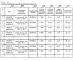
- the estimated position and posture error and the position and posture of own vehicle specified in Step S403 are stored in the vehicle position and posture-related data group 122 in a data format illustrated in Fig. 3 .
- Step S405 the on-vehicle control device 10 executes position and posture error transition estimation processing in order to estimate how the position and posture error will make transition in future.
- position and posture error transition estimation processing is executed by the future travel content estimation unit 108 and the future position and posture error specifying unit 104 of the on-vehicle control device 10 according to a processing flow 450 illustrated in Fig. 6 .
- the error of the future position and posture of own vehicle is estimated by using the current position and posture errors specified in Step S404 as an initial value. Details of the processing flow 450 of Fig. 6 will be described later.
- Step S406 the on-vehicle control device 10 executes suitable travel control level determination processing for determining a suitable travel control level in future travel control of the own vehicle.
- the suitable travel control level determination processing is executed by the allowable position and posture error specifying unit 105, the travel control content determination unit 106, the future travel content estimation unit 108, and the driver state specifying unit 111 of the on-vehicle control device 10, according to a processing flow 500 illustrated in Fig. 7 .
- the suitable travel control level corresponding to a future travel control content of the own vehicle is determined based on the error of the future position and posture of own vehicle estimated in Step S405. Details of the processing flow 500 of Fig. 7 will be described later.
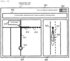
- Step S407 the on-vehicle control device 10 executes traveling control continuity information notification processing for notifying a driver of information relating to continuity of travel control of the own vehicle, based on the suitable travel control level determined in Step S406.
- traveling control continuity information notification processing is executed by the travel control continuity information determination unit 109 and the travel control continuity information output unit 110 of the on-vehicle control device 10, according to a processing flow 700 illustrated in Fig. 12 . Details of the processing flow 700 of Fig. 12 will be described later.
- the on-vehicle control device 10 determines the travel control content of the own vehicle in Step S408.
- information relating to an assumed travel route of the own vehicle is specified by the travel route information specifying unit 107 of the on-vehicle control device 10 with reference to the peripheral road map data group 121, based on information output from the travel route determination device 80.
- the information includes information relating to a road shape on the assumed travel route of the own vehicle .
- the travel control content of the own vehicle is determined by the travel control content determination unit 106 of the on-vehicle control device 10 based on information relating to the specified assumed travel route and the current travel control level.
- the travel control contents such as steering control or acceleration and deceleration control, that are needed for automatically travelling on the right and left turns and the curve are determined based on the road shape on the assumed travel route.
- Fig. 6 indicates the processing flow 450 of position and posture error transition estimation processing.
- Step S451 the future travel content estimation unit 108 acquires travel control plan information representing travel control content of the own vehicle.
- the travel control plan information is determined according to, for example, the travel control processing flow 400 of Fig. 5 based on the travel control content determined by the travel control content determination unit 106 in Step S408 of a processing cycle at the previous time.
- travel control plan information information representing a travel control content of the own vehicle at the time subsequent from the present time point, for example, information such as a target track or target speed profile indicating how to control the own vehicle is included.
- Step S453 the future travel content estimation unit 108 specifies the travel content of the own vehicle until to (to is an arbitrary value) second elapse based on the travel control plan information acquired in Step S451.
- the processing proceeds to Step S455.
- the future travel content estimation unit 108 estimates the travel content of the own vehicle until to seconds elapse in Step S454.
- the travel route information specifying unit 107 information relating to the assumed travel route of the own vehicle is specified in a method similar to Step S408 of Fig. 5 and matters how the driver drives the own vehicle for to seconds from the present time point based on the specified information is estimated.
- a traveling estimation method of the own vehicle for example, it may also simply estimate that the own vehicle continues to travel at a constant velocity or acceleration.
- the travel control content is temporarily calculated such that the travel content of the own vehicle may be estimated using external information obtained from the peripheral road map data group 121 or the external sensor group 50, based on a road shape represented by information relating to the assumed travel route specified by the travel route information specifying unit 107. It is preferable that the value of the to is greater than the maximum value of a verification target time T which will be described later.
- Step S455 the future position and posture error specifying unit 104 estimates a position and posture error until to seconds elapse based on the travel content of the own vehicle specified in Step S453 or the travel content of the own vehicle estimated in Step S454.
- the position and posture error in future is estimated by adding position and posture errors accumulated for to seconds from the present time due to traveling of the own vehicle on the assumed travel route to the initial value, using the current position and posture error specified in Step S404 of Fig. 5 as an initial value.
- Step S455 the future position and posture error specifying unit 104, basically, calculates the worst value of the assumed position and posture error by taking the travel content of the own vehicle into account for to seconds from the present time point.
- errors accumulated until to seconds elapse through the odometry are calculated by assuming a situation in which the position and posture cannot be specified with high-accuracy, for example, position estimation using land mark information.
- an advancing direction, a speed, angular velocity, or the like is determined when the own vehicle travels the assumed travel route based on the travel control content represented by travel control plan information acquired in Step S451 or the travel control content temporarily calculated in Step S454 and the position and posture error until to seconds elapse is estimated using the position and posture error calculation equation described above.
- the position and posture error is set for a point, for which the position and posture of own vehicle can be specified with high accuracy by land mark recognition, or the like, by taking specification accuracy of the position and posture of own vehicle at that point into account.
- the calculation may be made in such a way that the position and posture errors are not accumulated while traveling a road section in which the lane is recognizable in a state where the position in the lateral direction can be estimated with high accuracy by recognizing a lane of the traveling road.
- a transition of the position and posture error may be estimated based on land mark information that exists on the road that the own vehicle will travel and the recognition probability for land mark information. For example, errors which are accumulated so far may be reset when passing through a site for which accurate position information can be received from a road infrastructure.
- a surrounding environment of the own vehicle is also included, in addition to a feature inherent in the vehicle sensor group 60, for example, a quantization error.
- a slip ratio of the tire significantly influences the velocity error.
- the slip ratio of the tire is significantly influenced by a frictional resistance value of the road surface.
- frictional resistance values of respective roads may be stored in the peripheral road map data group 121 and the frictional resistance values may be referenced to correct the variance value of the velocity errors in such a way that a higher variance value is set to a road as the frictional resistance value of the road is increased.
- the road surface state such as freeze, rain, snow, or the like may be recognized based on information obtained from the external sensor group 50 or the wireless communication unit 30 and a change in the frictional resistance value from the recognized result may be estimated to correct a variance value of the velocity errors.
- ⁇ x(t + ⁇ t) ⁇ x(t) + ⁇ v(t) ⁇ ⁇ t by respectively setting ⁇ (t), ⁇ (t), and ⁇ y(t) to 0 as described above to rearrange the equation (1).
- the position error ⁇ x(t + ⁇ t) is accumulated in a form in which the velocity error ⁇ v(t) is set as inclination and is proportional to the elapsed time ⁇ t.
- the position and posture of own vehicle can be specified with a fixed high accuracy, irrespective of the elapsed time. For that reason, it is possible to measure how many position and posture errors are generated by the odometry by comparing the error of the position and posture of own vehicle in a case where land mark is recognized with the position and posture accuracy of own vehicle accuracy in a case where the position and posture of own vehicle is estimated by the odometry. It is possible to estimate the magnitude of the velocity error ⁇ v(t) by statistically obtaining the measurement results.
- Step S455 the future position and posture error specifying unit 104 estimates the position and posture error which includes the longitudinal direction of the own vehicle, that is, the position error ⁇ x(t + to) in the x-axis direction and the lateral direction of the own vehicle, that is, the position error ⁇ y(t + to) in the y-axis direction in future after a predetermined time to elapses from the present time t, based on the travel content of the own vehicle specified or estimated in Step S453 or S454.
- the position and posture error estimation method described above is an example. As long as it is possible to estimate the transition of position and posture error until at least to seconds elapse, the future position and posture error may be estimated by using any method.
- Step S455 When processing of Step S455 is executed, the future position and posture error specifying unit 104 ends position and posture error transition estimation processing illustrated in the processing flow 450 of Fig. 6 . With this, processing of Step S405 of Fig. 5 is completed.
- the future travel content estimation unit 108 executes processing of Step S453 or S454 based on information relating to the assumed travel route of the own vehicle specified by the travel route information specifying unit 107 so as to specify or estimate the travel content of the own vehicle according to the road shape on the assumed travel routes.
- the future position and posture error specifying unit 104 estimates the position and posture error of processing of Step S455 based on the processing result. That is, the future position and posture error specifying unit 104 performs processing of Step S455 so as to make it possible to estimate the position and posture error according to the road shape on the assumed travel route based on information specified by the travel route information specifying unit 107 .
- Fig. 7 illustrates a processing flow 500 of the suitable travel control level determination processing.
- Step S501 the travel control content determination unit 106 acquires a travel control level Lc according to the current travel control content of the own vehicle.
- Step S502 the travel control content determination unit 106 sets an initial value of variables L and Lo based on the current travel control level Lc acquired in Step S501.
- the current travel control level Lc acquired in Step S501 is set as the initial value of the variable L representing a travel control level being selected.
- the symbol ⁇ which indicates an invalid value is set as the initial value of the variable Lo indicating a lapse of setting of the suitable travel control level.
- the driver state specifying unit 111 specifies which state a driver of the own vehicle is in the current time and acquires the result.
- a state of a driver is detected based on an image obtained by capturing an expression, or the like of the driver by a camera or biological information (gaze, perspiration, pulse, body temperature, or the like) of the driver detected by various sensors.
- which state the driver is in any of an awakening state, a dozing state, an attention-distracting state, and the like is identified.
- a value indicating a detection-disabled state is acquired.
- the verification target time T for determining a suitable travel control level is determined based on the state of the driver of the own vehicle.
- Step S505 the future travel content estimation unit 108 specifies a future travel content of the own vehicle based on the verification target time T determined in Step S504.
- the travel content of the own vehicle for a verification target time T from the present time is specified.
- the future travel content estimation unit 108 can specify the travel content of the own vehicle until T seconds elapse by the method similar to, for example, Steps S451 to S454 of Fig. 6 . That is, the future travel content estimation unit 108 specifies the travel content of the own vehicle according to the road shape on the assumed travel route based on information relating to the assumed travel route of the own vehicle specified by the travel route information specifying unit 107. In this case, the travel content of the own vehicle may be included to specify at the time which is later than the verification target time T.
- the allowable position and posture error specifying unit 105 specifies an allowable range (allowable position and posture error range) of the position and posture error of the own vehicle in future travel control, that is, requested accuracy of the position and posture of own vehicle based on the current value of the variable L, the value of the verification target time T which is set in Step S504, and the future travel content of the own vehicle specified in Step S505 .
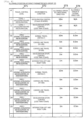
- the allowable position and posture error specifying unit 105 references the allowable position accuracy parameter data group 123 illustrated in Fig.
- the allowable position and posture error range according to a value of the travel control level represented by the variable L, regarding the travel content of the own vehicle in a period from the present time to a certain time point in future according to the verification target time T.
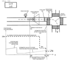
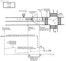
- the control level represented by the variable L is 3 and the travel content of the own vehicle in a period from the present time to the verification target time T later is a content indicating that the own vehicle turns right the intersection after traveling a straight course.
- allowable position errors in the longitudinal direction (x-axis direction) and the lateral direction (y-axis direction) at the time of traveling a straight course are obtained as 10 m and 0.
- the allowable position and posture error specifying unit 105 specifies an allowable range of position and posture error including an allowable range of position error of the own vehicle in the longitudinal direction, that is, the x-axis direction, and an allowable range of position error of the own vehicle in the lateral direction, that is, the y-axis direction.
- the allowable position and posture error specifying unit 105 determines a data record to be referenced in the allowable position accuracy parameter data group 123 and specifies the allowable position and posture error range by taking the future travel content of the own vehicle specified in Step S505 according to the road shape on the assumed travel route into account.
- the allowable position and posture error specifying unit 105 performs processing of Step S506 so as to make it possible to specify the allowable position and posture error range based on the road shape on the assumed travel route.
- the allowable position and posture error range may be specified regarding a time range which includes a future time point further later than the verification target time T.
- Step S507 the travel control content determination unit 106 compares the value of a period from the present time to the verification target time T among the position and posture errors estimated by the future position and posture error specifying unit 104 with the allowable position and posture error range in the travel control level according to the value of the variable L specified in Step S506. It is determined whether the position and posture error until the verification target time T seconds elapse is less than the allowable position and posture error range based on the comparison result. As a result, in a case where the position and posture error is less than the allowable position and posture error range all the time in a period of time from the present time to the verification target time T, the processing proceeds to Step S508.
- Step S511 the processing proceeds to Step S511.
- the period of time for which the position and posture error and the allowable position and posture error range are compared with each other in Step S507 may not necessarily coincide with the verification target time T.
- a comparison of the position and posture error with the allowable position and posture error range may be performed to determine, based on the comparison result, whether the position and posture error is less than or equal to the allowable position and posture error range.
- the comparison of the position and posture error with the allowable position and posture error range may be performed using discrete values of respective errors.
- the position and posture error which is estimated by the future position and posture error specifying unit 104 at predetermined discrete times in a period from the present time to the verification target time T, is compared with the allowable position and posture error range at respective time points. It may be determined, based on the comparison result, whether the position and posture error is less than or equal to the allowable position and posture error range.
- Step S508 the travel control content determination unit 106 substitutes the current value of the variable L into the variable Lo. That is, the value of the travel control level used when the allowable position and posture error range is specified in previous Step S506 is set as a suitable travel control level.
- the travel control level for which a confirmation whether requirements of the position and posture accuracy are satisfied or not is to be performed does not exist anymore and thus, the value of the variable Lo at that time is decided as the suitable travel control level of the own vehicle and the suitable travel control level determination processing is completed.
- the processing proceeds to Step S510.
- the value of the variable Lo is decided as the suitable travel control level of the own vehicle and suitable travel control level determination processing illustrated in the processing flow 500 of Fig. 7 is ended.
- Step S512 the travel control content determination unit 106 determines whether the current value of the variable L is less than or equal to 1 or not. As a result, when the variable L is less than or equal to 1, the processing proceeds to Step S513. On the other hand, when the variable L is greater than 1, the processing proceeds to Step S514. That is, when the relation of L > 1 is established, there is a possibility that in a lower travel control level, requirements of position and posture accuracy are satisfied and travel control obtained by degenerating the functionality can be executed and thus, the processing proceeds to Step S514 and suitable travel control level determination processing is continued.
- Step S513 the travel control content determination unit 106 sets the value of the variable Lo to 0. That is, the suitable travel control level is set to 0 such that the driver drives manually without performing automatic driving control.
- Step S512 is executed, suitable travel control level determination processing illustrated in the processing flow 500 of Fig. 7 is ended.
- Step S514 the travel control content determination unit 106 decreases the value of the variable L by 1. That is, the value of the travel control level used when the allowable position and posture error range is specified in previous Step S506 is decremented by 1 so as to regard the lower travel control level as a processing target thereafter.
- Step S514 processing returns to Step S503 and processing described above is repeated using the value of the variable L after being decreased.
- suitable travel control level determination processing illustrated in the processing flow 500 of Fig. 7 is performed.
- the suitable travel control level corresponding to the future travel control content of the own vehicle is set by the travel control content determination unit 106.
- Step S503 the state of the driver is specified in Step S503 and subsequently, the verification target time T is set based on the state of the driver in Step S504.
- the set value of the verification target time T is represented as T1.
- Step S505 the travel track 550 of Fig. 8 and a travel speed profile of the own vehicle on the travel track 550 are specified as the travel contents of the own vehicle in a period from the present time until T1 seconds elapse. With this, an estimated position 572 of the own vehicle after T1 seconds is specified.
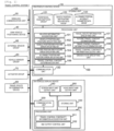
- the related information acquisition unit 101, the allowable position and posture error specifying unit 105, the travel control content determination unit 106, the travel route information specifying unit 107, the future travel content estimation unit 108, the travel control continuity information determination unit 109, the travel control continuity information output unit 110, and the driver state specifying unit 111 are the same as those described in the first embodiment, respectively.
- the processing unit 100A executes a predetermined operation program stored in the storing unit 120 so as to make it possible to perform processing corresponding to the respective units.
Landscapes
- Engineering & Computer Science (AREA)
- Automation & Control Theory (AREA)
- Mechanical Engineering (AREA)
- Transportation (AREA)
- Physics & Mathematics (AREA)
- Human Computer Interaction (AREA)
- Mathematical Physics (AREA)
- General Physics & Mathematics (AREA)
- Traffic Control Systems (AREA)
- Navigation (AREA)
- Aviation & Aerospace Engineering (AREA)
- Radar, Positioning & Navigation (AREA)
- Remote Sensing (AREA)
- Control Of Driving Devices And Active Controlling Of Vehicle (AREA)
Claims (9)
- Dispositif de commande embarqué (10) qui est monté sur un véhicule pour commander le déplacement du véhicule, le dispositif comprenant :une unité de spécification d'erreur de position de véhicule (103) qui estime une erreur de position du véhicule ;une unité de détermination d'informations de continuité de commande de déplacement (109) qui détermine des informations de continuité de commande de déplacement concernant la continuité d'un état de commande de déplacement du véhicule sur la base de l'erreur de position du véhicule estimée par l'unité de spécification d'erreur de position de véhicule (103) ; etune unité de sortie d'informations de continuité de commande de déplacement (110) qui délivre en sortie les informations de continuité de commande de déplacement concernant la continuité de l'état de commande de déplacement du véhicule déterminée par l'unité de détermination d'informations de continuité de commande de déplacement (109), caractérisé par une unité de spécification d'erreur de position future qui estime une erreur de position future du véhicule sur la base de l'erreur de position du véhicule estimée par l'unité de spécification d'erreur de position de véhicule (103),dans lequel l'unité de détermination d'informations de continuité de commande de déplacement (109) détermine les informations de continuité de commande de déplacement concernant la continuité de l'état de commande de déplacement du véhicule sur la base de l'erreur de position future estimée par l'unité de spécification d'erreur de position future.
- Dispositif de commande embarqué (10) selon la revendication 1, comprenant en outre :une unité de spécification d'erreur de position admissible (105) qui détermine une plage admissible d'une erreur de position (561) dans une commande de déplacement future du véhicule,dans lequel l'unité de détermination d'informations de continuité de commande de déplacement (109) détermine les informations de continuité de commande de déplacement concernant la continuité de l'état de commande de déplacement du véhicule sur la base d'un résultat de comparaison de l'erreur de position future estimée par l'unité de spécification d'erreur de position future et de la plage admissible de l'erreur de position (561) déterminée par l'unité de spécification d'erreur de position admissible (105).
- Dispositif de commande embarqué (10) selon la revendication 2,dans lequel l'unité de spécification d'erreur de position future estime une erreur de position dans une direction longitudinale (304) qui représente l'erreur de position future dans une direction parallèle à une direction d'avancement d'une route de déplacement du véhicule et une erreur de position dans une direction latérale (305) qui représente l'erreur de position future dans une direction orthogonale à la direction d'avancement de la route de déplacement,l'unité de spécification d'erreur de position admissible (105) détermine une erreur admissible dans une direction longitudinale (373) qui représente la plage admissible de l'erreur de position (561) dans la direction parallèle à la direction d'avancement de la route de déplacement du véhicule et une erreur admissible dans une direction latérale (374) qui représente la plage admissible de l'erreur de position (561) dans la direction orthogonale à la direction d'avancement de la route de déplacement du véhicule, etl'unité de détermination d'informations de continuité de commande de déplacement (109) détermine des informations de continuité de commande de déplacement concernant la continuité de l'état de commande de déplacement du véhicule sur la base d'un résultat de comparaison de l'erreur de position dans une direction longitudinale (304) et/ou de l'erreur de position dans une direction latérale (305) estimée par l'unité de spécification d'erreur de position future et de l'erreur admissible dans une direction longitudinale (373) et/ou de l'erreur admissible dans une direction latérale (374) déterminée par l'unité de spécification d'erreur de position admissible (105).
- Dispositif de commande embarqué (10) selon la revendication 2 ou 3, comprenant en outre :une unité de spécification d'informations d'itinéraire de déplacement (107) qui spécifie des informations concernant un itinéraire de déplacement supposé du véhicule,dans lequel l'unité de spécification d'erreur de position future estime l'erreur de position future du véhicule sur la base des informations concernant l'itinéraire de déplacement supposé spécifié par l'unité de spécification d'informations d'itinéraire de déplacement (107).
- Dispositif de commande embarqué (10) selon la revendication 4 citant la revendication 2,dans lequel les informations concernant l'itinéraire de déplacement supposé comprennent des informations concernant une forme de route sur l'itinéraire de déplacement supposé, etl'unité de spécification d'erreur de position admissible (105) détermine la plage admissible de l'erreur de position (561) sur la base de la forme de route sur l'itinéraire de déplacement supposé.
- Dispositif de commande embarqué (10) selon la revendication 1, comprenant en outre :une unité de détermination de contenu de commande de déplacement (106) qui détermine un contenu de commande de déplacement du véhicule,dans lequel l'unité de spécification d'erreur de position future estime une erreur de position future du véhicule sur la base du contenu de commande de déplacement du véhicule déterminé par l'unité de détermination de contenu de commande de déplacement (106).
- Dispositif de commande embarqué (10) selon la revendication 2, comprenant en outre :une unité de détermination de contenu de commande de déplacement (106) qui détermine un contenu de commande de déplacement du véhicule,dans lequel l'unité de spécification d'erreur de position admissible (105) détermine la plage admissible de l'erreur de position (561) sur la base du contenu de commande de déplacement du véhicule déterminé par l'unité de détermination de contenu de commande de déplacement (106).
- Dispositif de commande embarqué (10) selon la revendication 7,dans lequel l'unité de spécification d'erreur de position admissible (105) sélectionne l'un quelconque de niveaux de commande de déplacement (371) parmi une pluralité de niveaux de commande de déplacement (371) qui sont définis à l'avance en fonction du contenu de commande de déplacement du véhicule et détermine la plage admissible de l'erreur de position (561) sur la base du niveau de commande de déplacement sélectionné (371),l'unité de détermination de contenu de commande de déplacement (106) définit l'un quelconque des niveaux de commande de déplacement (371) parmi la pluralité de niveaux de commande de déplacement (371) en tant que niveau de commande de déplacement approprié (752) correspondant à un contenu de commande de déplacement futur du véhicule, sur la base d'un résultat de comparaison de l'erreur de position future estimée par l'unité de spécification d'erreur de position future et de la plage admissible de l'erreur de position (561) déterminée par l'unité de spécification d'erreur de position admissible (105), etl'unité de détermination d'informations de continuité de commande de déplacement (109) détermine des informations de continuité de commande de déplacement concernant la continuité de l'état de commande de déplacement du véhicule sur la base du niveau de commande de déplacement approprié (752) défini par l'unité de détermination de contenu de commande de déplacement (106).
- Dispositif de commande embarqué (10) selon la revendication 2, comprenant en outre :une unité de spécification d'état de conducteur (111) qui estime un état d'un conducteur du véhicule,dans lequel l'unité de spécification d'erreur de position admissible (105) détermine la plage admissible de l'erreur de position (561) sur la base d'un temps cible de vérification déterminé en fonction de l'état du conducteur du véhicule estimé par l'unité de spécification d'état de conducteur (111).
Applications Claiming Priority (2)
| Application Number | Priority Date | Filing Date | Title |
|---|---|---|---|
| JP2015005314A JP6298772B2 (ja) | 2015-01-14 | 2015-01-14 | 車載用制御装置、自車位置姿勢特定装置、車載用表示装置 |
| PCT/JP2015/084545 WO2016114044A1 (fr) | 2015-01-14 | 2015-12-09 | Dispositif de commande embarqué, dispositif d'identification de position et d'orientation de véhicule hôte, et dispositif d'affichage embarqué |
Publications (3)
| Publication Number | Publication Date |
|---|---|
| EP3246893A1 EP3246893A1 (fr) | 2017-11-22 |
| EP3246893A4 EP3246893A4 (fr) | 2019-04-17 |
| EP3246893B1 true EP3246893B1 (fr) | 2024-07-10 |
Family
ID=56405599
Family Applications (1)
| Application Number | Title | Priority Date | Filing Date |
|---|---|---|---|
| EP15877995.9A Active EP3246893B1 (fr) | 2015-01-14 | 2015-12-09 | Dispositif de commande embarqué, dispositif d'identification de position et d'orientation de véhicule hôte, et dispositif d'affichage embarqué |
Country Status (5)
| Country | Link |
|---|---|
| US (1) | US10303168B2 (fr) |
| EP (1) | EP3246893B1 (fr) |
| JP (1) | JP6298772B2 (fr) |
| CN (1) | CN107077794B (fr) |
| WO (1) | WO2016114044A1 (fr) |
Families Citing this family (47)
| Publication number | Priority date | Publication date | Assignee | Title |
|---|---|---|---|---|
| EP3144918B1 (fr) * | 2015-09-21 | 2018-01-10 | Urban Software Institute GmbH | Système informatique et procédé de surveillance d'un système de trafic |
| JP6815724B2 (ja) * | 2015-11-04 | 2021-01-20 | トヨタ自動車株式会社 | 自動運転システム |
| JP6590270B2 (ja) * | 2016-05-16 | 2019-10-16 | 本田技研工業株式会社 | 車両制御システム、車両制御方法、および車両制御プログラム |
| KR101793223B1 (ko) * | 2016-07-13 | 2017-11-03 | 모바일 어플라이언스 주식회사 | 차량 운전 보조장치 |
| JP6312754B2 (ja) * | 2016-08-04 | 2018-04-18 | 三菱電機株式会社 | 車両走行制御装置および車両走行制御方法 |
| JP7214329B2 (ja) * | 2016-08-09 | 2023-01-30 | 日立Astemo株式会社 | 表示内容認識装置、および車両制御装置 |
| JP6831190B2 (ja) | 2016-08-15 | 2021-02-17 | トヨタ自動車株式会社 | 自動運転車両の制御システム及び制御方法 |
| EP3506236B1 (fr) * | 2016-08-25 | 2022-01-12 | Sony Group Corporation | Dispositif et procédé de commande d'état de véhicule, et véhicule |
| JP6544320B2 (ja) * | 2016-08-26 | 2019-07-17 | トヨタ自動車株式会社 | 自動運転車両の制御システム及び制御方法 |
| US10019008B2 (en) * | 2016-09-28 | 2018-07-10 | Baidu Usa Llc | Sideslip compensated control method for autonomous vehicles |
| JP6805704B2 (ja) * | 2016-10-11 | 2020-12-23 | 日産自動車株式会社 | 経路選択方法及び経路選択装置 |
| JP6855759B2 (ja) * | 2016-11-11 | 2021-04-07 | トヨタ自動車株式会社 | 自動運転車両の制御システム |
| WO2018105074A1 (fr) * | 2016-12-08 | 2018-06-14 | 三菱電機株式会社 | Dispositif de commande de rapport et procédé de commande de rapport |
| JP6678609B2 (ja) * | 2017-03-01 | 2020-04-08 | 株式会社東芝 | 情報処理装置、情報処理方法、情報処理プログラム、および移動体 |
| JP2018147247A (ja) * | 2017-03-06 | 2018-09-20 | オムロン株式会社 | 運転者身体コンディション回復支援装置、方法およびプログラム |
| JP6508845B2 (ja) | 2017-06-02 | 2019-05-08 | 本田技研工業株式会社 | 車両制御システム、車両制御方法、およびプログラム |
| RU2737645C1 (ru) | 2017-07-28 | 2020-12-01 | Ниссан Мотор Ко., Лтд. | Способ отображения окружающей обстановки и устройство отображения окружающей обстановки |
| JP6747405B2 (ja) | 2017-08-25 | 2020-08-26 | トヨタ自動車株式会社 | 自車位置自信度演算装置 |
| JP6863194B2 (ja) * | 2017-09-19 | 2021-04-21 | トヨタ自動車株式会社 | 自動運転システム |
| JP6859927B2 (ja) * | 2017-11-06 | 2021-04-14 | トヨタ自動車株式会社 | 自車位置推定装置 |
| JP2019185225A (ja) * | 2018-04-04 | 2019-10-24 | 株式会社デンソー | 車両の自動運転制御装置 |
| JP6985207B2 (ja) * | 2018-05-09 | 2021-12-22 | トヨタ自動車株式会社 | 自動運転システム |
| JP6971197B2 (ja) * | 2018-05-22 | 2021-11-24 | ヤンマーパワーテクノロジー株式会社 | 作業車両 |
| DE102018005869A1 (de) * | 2018-07-25 | 2020-01-30 | Zf Active Safety Gmbh | System zur Erstellung eines Umgebungsmodells eines Fahrzeugs |
| WO2020039530A1 (fr) * | 2018-08-23 | 2020-02-27 | 三菱電機株式会社 | Dispositif de sélection de conducteur et procédé de sélection de conducteur |
| CN110866429B (zh) | 2018-08-28 | 2024-03-08 | 阿里巴巴集团控股有限公司 | 漏扫识别方法、装置、自助收银终端及系统 |
| CN109814548B (zh) * | 2018-12-29 | 2022-02-15 | 广州蓝海机器人系统有限公司 | 一种基于室内微波基站的导航方法和agv |
| JP7081556B2 (ja) * | 2019-04-04 | 2022-06-07 | トヨタ自動車株式会社 | 車両制御装置 |
| JP7202982B2 (ja) * | 2019-06-28 | 2023-01-12 | 日産自動車株式会社 | 運転支援方法及び運転支援装置 |
| WO2021005687A1 (fr) * | 2019-07-08 | 2021-01-14 | 三菱電機株式会社 | Dispositif et procédé d'estimation de position |
| JP7204612B2 (ja) | 2019-08-06 | 2023-01-16 | 株式会社東芝 | 位置姿勢推定装置、位置姿勢推定方法及びプログラム |
| EP4018338B1 (fr) * | 2019-08-23 | 2023-09-20 | Volvo Truck Corporation | Procédure de quantification d'un parcours de véhicule en suivant la performance. |
| US11674819B2 (en) * | 2019-12-30 | 2023-06-13 | Subaru Corporation | Mobility information provision system, server, and vehicle |
| JP7036136B2 (ja) * | 2020-03-02 | 2022-03-15 | トヨタ自動車株式会社 | 車載装置およびプログラム |
| JP7437982B2 (ja) * | 2020-03-10 | 2024-02-26 | 本田技研工業株式会社 | 移動体制御装置、移動体制御方法、及びプログラム |
| DE102020108907B4 (de) * | 2020-03-31 | 2022-04-21 | Daimler Ag | Verfahren zur landmarkenbasierten Lokalisierung eines Fahrzeugs |
| CN112748453B (zh) * | 2020-08-13 | 2023-11-17 | 腾讯科技(深圳)有限公司 | 道路侧定位方法、装置、设备及存储介质 |
| WO2022097376A1 (fr) * | 2020-11-06 | 2022-05-12 | ソニーグループ株式会社 | Dispositif, procédé et programme de traitement de signal et système de commande de véhicule |
| CN112959248B (zh) * | 2021-02-05 | 2022-12-02 | 机械工业第九设计研究院股份有限公司 | 一种汽车零件生产用汽车工装夹具及使用方法 |
| JP2022123940A (ja) * | 2021-02-15 | 2022-08-25 | 本田技研工業株式会社 | 車両制御装置 |
| JP7676897B2 (ja) * | 2021-04-14 | 2025-05-15 | トヨタ自動車株式会社 | 自動運転装置 |
| JP7610480B2 (ja) * | 2021-07-14 | 2025-01-08 | 日立Astemo株式会社 | 車両制御装置 |
| US12110017B2 (en) * | 2022-03-01 | 2024-10-08 | Ford Global Technologies, Llc | Street lane-level matching method for automotive applications |
| US12384411B2 (en) * | 2022-09-27 | 2025-08-12 | Robert Bosch Gmbh | Systems and methods for distribution-aware goal prediction for modular autonomous vehicle control |
| US12415510B1 (en) * | 2022-10-31 | 2025-09-16 | Zoox, Inc. | Simulated vehicle position errors in driving simulations |
| DE102023208926A1 (de) * | 2023-09-14 | 2025-03-20 | Robert Bosch Gesellschaft mit beschränkter Haftung | Verfahren und Vorrichtung zum Erstellen einer digitalen Karte und Betreiben eines automatisierten Fahrzeugs |
| JP2025082342A (ja) * | 2023-11-17 | 2025-05-29 | 株式会社日立製作所 | 死角領域推定装置、走行環境作成装置、車両制御装置及び車両 |
Citations (1)
| Publication number | Priority date | Publication date | Assignee | Title |
|---|---|---|---|---|
| EP2264404B1 (fr) * | 2009-06-18 | 2014-03-12 | Clarion Co., Ltd. | Appareil de détection de position et programme de détection de position |
Family Cites Families (31)
| Publication number | Priority date | Publication date | Assignee | Title |
|---|---|---|---|---|
| JPH07117581B2 (ja) * | 1989-07-19 | 1995-12-18 | トヨタ自動車株式会社 | 自動車用航法装置 |
| US6021367A (en) * | 1994-08-24 | 2000-02-01 | Ford Global Technologies, Inc. | Vehicle steering system and method for controlling vehicle direction through differential braking of left and right road wheels |
| JP3388132B2 (ja) * | 1997-04-09 | 2003-03-17 | 本田技研工業株式会社 | 車両制御装置 |
| JP3548009B2 (ja) * | 1998-07-10 | 2004-07-28 | 本田技研工業株式会社 | 車両用走行制御装置 |
| JP3167987B2 (ja) * | 1999-08-06 | 2001-05-21 | 富士重工業株式会社 | カーブ進入制御装置 |
| JP3167990B2 (ja) * | 1999-09-14 | 2001-05-21 | 富士重工業株式会社 | カーブ進入制御装置 |
| JP3758443B2 (ja) | 2000-01-19 | 2006-03-22 | 日産自動車株式会社 | 走行状態提示装置 |
| JP3878008B2 (ja) * | 2001-12-07 | 2007-02-07 | 株式会社日立製作所 | 車両用走行制御装置及び地図情報データ記録媒体 |
| DE10218924A1 (de) * | 2002-04-27 | 2003-11-06 | Bosch Gmbh Robert | Verfahren und Vorrichtung zur Kursprädiktion bei Kraftfahrzeugen |
| US7522091B2 (en) * | 2002-07-15 | 2009-04-21 | Automotive Systems Laboratory, Inc. | Road curvature estimation system |
| US7272482B2 (en) * | 2002-09-30 | 2007-09-18 | Nissan Motor Co., Ltd. | Preceding-vehicle following control system |
| US7512475B2 (en) * | 2004-03-19 | 2009-03-31 | Delphi Technologies, Inc. | Automatic lateral acceleration limiting and non threat target rejection |
| US7751973B2 (en) * | 2004-05-04 | 2010-07-06 | Visteon Global Technologies, Inc. | Curve warning system |
| US7974778B2 (en) * | 2004-09-17 | 2011-07-05 | Honda Motor Co., Ltd. | Vehicular control object determination system and vehicular travel locus estimation system |
| JP4622453B2 (ja) * | 2004-10-27 | 2011-02-02 | 日産自動車株式会社 | 自動操舵車両 |
| EP1659367B1 (fr) * | 2004-11-19 | 2008-09-03 | Harman Becker Automotive Systems GmbH | Navigation d'un véhicule pour l'avertissement intégré de virages basé sur les modèles clothoides |
| US7474961B2 (en) * | 2005-02-04 | 2009-01-06 | Visteon Global Technologies, Inc. | System to determine the path of a vehicle |
| JP4639997B2 (ja) * | 2005-02-18 | 2011-02-23 | トヨタ自動車株式会社 | 車両の減速制御装置 |
| US7792624B2 (en) * | 2005-10-05 | 2010-09-07 | Nissan Motor Co., Ltd. | Cruise control system |
| JP4169065B2 (ja) * | 2006-02-13 | 2008-10-22 | 株式会社デンソー | 車両制御装置 |
| JP5162103B2 (ja) * | 2006-05-15 | 2013-03-13 | トヨタ自動車株式会社 | 支援制御装置 |
| JP2008012975A (ja) * | 2006-07-04 | 2008-01-24 | Xanavi Informatics Corp | 車両走行制御システム |
| JP4860391B2 (ja) * | 2006-07-27 | 2012-01-25 | 本田技研工業株式会社 | 車両の走行安全装置 |
| JP2008070261A (ja) * | 2006-09-14 | 2008-03-27 | Toshiba Corp | 位置把握システムとその装置及び位置把握方法 |
| JP4944551B2 (ja) * | 2006-09-26 | 2012-06-06 | 日立オートモティブシステムズ株式会社 | 走行制御装置、走行制御方法、および、走行制御プログラム |
| US8180513B2 (en) * | 2008-05-05 | 2012-05-15 | Southwest Research Institute | Autonomous ground vehicle control system for high-speed and safe operation |
| JP2010076697A (ja) * | 2008-09-29 | 2010-04-08 | Advics Co Ltd | 車両の速度制御装置 |
| JP2011107108A (ja) * | 2009-11-20 | 2011-06-02 | Toyota Motor Corp | 移動体用測位装置 |
| US8509982B2 (en) * | 2010-10-05 | 2013-08-13 | Google Inc. | Zone driving |
| JP5890736B2 (ja) * | 2012-04-13 | 2016-03-22 | 本田技研工業株式会社 | 走行支援制御装置 |
| JP2014106854A (ja) * | 2012-11-29 | 2014-06-09 | Toyota Infotechnology Center Co Ltd | 自動運転車両制御装置および方法 |
-
2015
- 2015-01-14 JP JP2015005314A patent/JP6298772B2/ja active Active
- 2015-12-09 EP EP15877995.9A patent/EP3246893B1/fr active Active
- 2015-12-09 WO PCT/JP2015/084545 patent/WO2016114044A1/fr not_active Ceased
- 2015-12-09 US US15/522,410 patent/US10303168B2/en active Active
- 2015-12-09 CN CN201580057238.0A patent/CN107077794B/zh active Active
Patent Citations (1)
| Publication number | Priority date | Publication date | Assignee | Title |
|---|---|---|---|---|
| EP2264404B1 (fr) * | 2009-06-18 | 2014-03-12 | Clarion Co., Ltd. | Appareil de détection de position et programme de détection de position |
Also Published As
| Publication number | Publication date |
|---|---|
| JP6298772B2 (ja) | 2018-03-20 |
| CN107077794A (zh) | 2017-08-18 |
| CN107077794B (zh) | 2020-04-21 |
| WO2016114044A1 (fr) | 2016-07-21 |
| US20170329328A1 (en) | 2017-11-16 |
| EP3246893A4 (fr) | 2019-04-17 |
| US10303168B2 (en) | 2019-05-28 |
| EP3246893A1 (fr) | 2017-11-22 |
| JP2016130971A (ja) | 2016-07-21 |
Similar Documents
| Publication | Publication Date | Title |
|---|---|---|
| EP3246893B1 (fr) | Dispositif de commande embarqué, dispositif d'identification de position et d'orientation de véhicule hôte, et dispositif d'affichage embarqué | |
| CN111176270B (zh) | 使用动态地标的定位 | |
| CN107000752B (zh) | 用于在其周围环境中定位车辆的方法和设备 | |
| CN106352867B (zh) | 用于确定车辆自身位置的方法和设备 | |
| US9283967B2 (en) | Accurate curvature estimation algorithm for path planning of autonomous driving vehicle | |
| JP5472163B2 (ja) | 速度規制値通知装置及び速度規制値通知システム | |
| US20170154531A1 (en) | Drive support apparatus | |
| US20160185348A1 (en) | Vehicle collision avoidance supporting apparatus and vehicle collision avoidance supporting method | |
| JP6451857B2 (ja) | 走行制御装置の制御方法および走行制御装置 | |
| CN109752741A (zh) | 车辆定位设备 | |
| CN105937912A (zh) | 车辆的地图数据处理装置 | |
| US11002553B2 (en) | Method and device for executing at least one measure for increasing the safety of a vehicle | |
| CN120970629A (zh) | 驾驶员辅助系统和方法 | |
| CN113306559A (zh) | 在路形估计中对于垂直道路曲度的补偿 | |
| CN115214667B (zh) | 车辆控制装置、存储介质以及车辆控制方法 | |
| JP6971315B2 (ja) | 情報管理装置 | |
| EP4130669A1 (fr) | Dispositif et procédé pour générer des informations de voie | |
| JP2019174191A (ja) | データ構造、情報送信装置、制御方法、プログラム及び記憶媒体 | |
| EP3339808B1 (fr) | Positionnement d'objets dans un affichage de réalité augmentée | |
| JP5666401B2 (ja) | ナビゲーションシステム、ナビゲーション装置、およびナビゲーションシステムの動作方法 | |
| CN116222587B (zh) | 位置精度判定装置、存储介质以及判定方法 | |
| JP2022054223A (ja) | 位置推定装置 | |
| CN116645651B (zh) | 道路端推测装置、道路端推测方法及计算机程序产品 | |
| CN116022131A (zh) | 道路信息处理系统 | |
| JP7160913B2 (ja) | 交通関与体の配向を推定するためのシステム及び方法 |
Legal Events
| Date | Code | Title | Description |
|---|---|---|---|
| STAA | Information on the status of an ep patent application or granted ep patent |
Free format text: STATUS: THE INTERNATIONAL PUBLICATION HAS BEEN MADE |
|
| PUAI | Public reference made under article 153(3) epc to a published international application that has entered the european phase |
Free format text: ORIGINAL CODE: 0009012 |
|
| STAA | Information on the status of an ep patent application or granted ep patent |
Free format text: STATUS: REQUEST FOR EXAMINATION WAS MADE |
|
| 17P | Request for examination filed |
Effective date: 20170814 |
|
| AK | Designated contracting states |
Kind code of ref document: A1 Designated state(s): AL AT BE BG CH CY CZ DE DK EE ES FI FR GB GR HR HU IE IS IT LI LT LU LV MC MK MT NL NO PL PT RO RS SE SI SK SM TR |
|
| AX | Request for extension of the european patent |
Extension state: BA ME |
|
| DAV | Request for validation of the european patent (deleted) | ||
| DAX | Request for extension of the european patent (deleted) | ||
| RIC1 | Information provided on ipc code assigned before grant |
Ipc: B60R 21/00 20060101ALI20181127BHEP Ipc: G08G 1/16 20060101AFI20181127BHEP Ipc: G08G 1/0962 20060101ALI20181127BHEP Ipc: B60W 50/14 20120101ALI20181127BHEP Ipc: G05D 1/00 20060101ALI20181127BHEP Ipc: B60W 40/02 20060101ALI20181127BHEP |
|
| A4 | Supplementary search report drawn up and despatched |
Effective date: 20190315 |
|
| RIC1 | Information provided on ipc code assigned before grant |
Ipc: G05D 1/00 20060101ALI20190311BHEP Ipc: B60W 40/02 20060101ALI20190311BHEP Ipc: B60R 21/00 20060101ALI20190311BHEP Ipc: G08G 1/0962 20060101ALI20190311BHEP Ipc: G08G 1/16 20060101AFI20190311BHEP Ipc: B60W 50/14 20120101ALI20190311BHEP |
|
| STAA | Information on the status of an ep patent application or granted ep patent |
Free format text: STATUS: EXAMINATION IS IN PROGRESS |
|
| 17Q | First examination report despatched |
Effective date: 20210610 |
|
| RAP3 | Party data changed (applicant data changed or rights of an application transferred) |
Owner name: HITACHI ASTEMO, LTD. |
|
| GRAP | Despatch of communication of intention to grant a patent |
Free format text: ORIGINAL CODE: EPIDOSNIGR1 |
|
| STAA | Information on the status of an ep patent application or granted ep patent |
Free format text: STATUS: GRANT OF PATENT IS INTENDED |
|
| RIC1 | Information provided on ipc code assigned before grant |
Ipc: B60W 50/029 20120101ALI20240126BHEP Ipc: B60W 50/02 20120101ALI20240126BHEP Ipc: B60W 40/10 20120101ALI20240126BHEP Ipc: B60W 40/00 20060101ALI20240126BHEP Ipc: G05D 1/00 20060101ALI20240126BHEP Ipc: G08G 1/0962 20060101ALI20240126BHEP Ipc: B60W 50/14 20120101ALI20240126BHEP Ipc: B60W 40/02 20060101ALI20240126BHEP Ipc: B60R 21/00 20060101ALI20240126BHEP Ipc: G08G 1/16 20060101AFI20240126BHEP |
|
| INTG | Intention to grant announced |
Effective date: 20240216 |
|
| GRAS | Grant fee paid |
Free format text: ORIGINAL CODE: EPIDOSNIGR3 |
|
| GRAA | (expected) grant |
Free format text: ORIGINAL CODE: 0009210 |
|
| STAA | Information on the status of an ep patent application or granted ep patent |
Free format text: STATUS: THE PATENT HAS BEEN GRANTED |
|
| AK | Designated contracting states |
Kind code of ref document: B1 Designated state(s): AL AT BE BG CH CY CZ DE DK EE ES FI FR GB GR HR HU IE IS IT LI LT LU LV MC MK MT NL NO PL PT RO RS SE SI SK SM TR |
|
| REG | Reference to a national code |
Ref country code: CH Ref legal event code: EP |
|
| REG | Reference to a national code |
Ref country code: DE Ref legal event code: R096 Ref document number: 602015089203 Country of ref document: DE |
|
| REG | Reference to a national code |
Ref country code: LT Ref legal event code: MG9D |
|
| REG | Reference to a national code |
Ref country code: NL Ref legal event code: MP Effective date: 20240710 |
|
| PG25 | Lapsed in a contracting state [announced via postgrant information from national office to epo] |
Ref country code: PT Free format text: LAPSE BECAUSE OF FAILURE TO SUBMIT A TRANSLATION OF THE DESCRIPTION OR TO PAY THE FEE WITHIN THE PRESCRIBED TIME-LIMIT Effective date: 20241111 |
|
| REG | Reference to a national code |
Ref country code: AT Ref legal event code: MK05 Ref document number: 1702752 Country of ref document: AT Kind code of ref document: T Effective date: 20240710 |
|
| PG25 | Lapsed in a contracting state [announced via postgrant information from national office to epo] |
Ref country code: NL Free format text: LAPSE BECAUSE OF FAILURE TO SUBMIT A TRANSLATION OF THE DESCRIPTION OR TO PAY THE FEE WITHIN THE PRESCRIBED TIME-LIMIT Effective date: 20240710 |
|
| PG25 | Lapsed in a contracting state [announced via postgrant information from national office to epo] |
Ref country code: PT Free format text: LAPSE BECAUSE OF FAILURE TO SUBMIT A TRANSLATION OF THE DESCRIPTION OR TO PAY THE FEE WITHIN THE PRESCRIBED TIME-LIMIT Effective date: 20241111 Ref country code: NL Free format text: LAPSE BECAUSE OF FAILURE TO SUBMIT A TRANSLATION OF THE DESCRIPTION OR TO PAY THE FEE WITHIN THE PRESCRIBED TIME-LIMIT Effective date: 20240710 |
|
| PG25 | Lapsed in a contracting state [announced via postgrant information from national office to epo] |
Ref country code: NO Free format text: LAPSE BECAUSE OF FAILURE TO SUBMIT A TRANSLATION OF THE DESCRIPTION OR TO PAY THE FEE WITHIN THE PRESCRIBED TIME-LIMIT Effective date: 20241010 |
|
| PG25 | Lapsed in a contracting state [announced via postgrant information from national office to epo] |
Ref country code: FI Free format text: LAPSE BECAUSE OF FAILURE TO SUBMIT A TRANSLATION OF THE DESCRIPTION OR TO PAY THE FEE WITHIN THE PRESCRIBED TIME-LIMIT Effective date: 20240710 Ref country code: PL Free format text: LAPSE BECAUSE OF FAILURE TO SUBMIT A TRANSLATION OF THE DESCRIPTION OR TO PAY THE FEE WITHIN THE PRESCRIBED TIME-LIMIT Effective date: 20240710 Ref country code: GR Free format text: LAPSE BECAUSE OF FAILURE TO SUBMIT A TRANSLATION OF THE DESCRIPTION OR TO PAY THE FEE WITHIN THE PRESCRIBED TIME-LIMIT Effective date: 20241011 |
|
| PG25 | Lapsed in a contracting state [announced via postgrant information from national office to epo] |
Ref country code: BG Free format text: LAPSE BECAUSE OF FAILURE TO SUBMIT A TRANSLATION OF THE DESCRIPTION OR TO PAY THE FEE WITHIN THE PRESCRIBED TIME-LIMIT Effective date: 20240710 |
|
| PG25 | Lapsed in a contracting state [announced via postgrant information from national office to epo] |
Ref country code: LV Free format text: LAPSE BECAUSE OF FAILURE TO SUBMIT A TRANSLATION OF THE DESCRIPTION OR TO PAY THE FEE WITHIN THE PRESCRIBED TIME-LIMIT Effective date: 20240710 |
|
| PG25 | Lapsed in a contracting state [announced via postgrant information from national office to epo] |
Ref country code: IS Free format text: LAPSE BECAUSE OF FAILURE TO SUBMIT A TRANSLATION OF THE DESCRIPTION OR TO PAY THE FEE WITHIN THE PRESCRIBED TIME-LIMIT Effective date: 20241110 Ref country code: AT Free format text: LAPSE BECAUSE OF FAILURE TO SUBMIT A TRANSLATION OF THE DESCRIPTION OR TO PAY THE FEE WITHIN THE PRESCRIBED TIME-LIMIT Effective date: 20240710 |
|
| PG25 | Lapsed in a contracting state [announced via postgrant information from national office to epo] |
Ref country code: HR Free format text: LAPSE BECAUSE OF FAILURE TO SUBMIT A TRANSLATION OF THE DESCRIPTION OR TO PAY THE FEE WITHIN THE PRESCRIBED TIME-LIMIT Effective date: 20240710 |
|
| PG25 | Lapsed in a contracting state [announced via postgrant information from national office to epo] |
Ref country code: RS Free format text: LAPSE BECAUSE OF FAILURE TO SUBMIT A TRANSLATION OF THE DESCRIPTION OR TO PAY THE FEE WITHIN THE PRESCRIBED TIME-LIMIT Effective date: 20241010 Ref country code: ES Free format text: LAPSE BECAUSE OF FAILURE TO SUBMIT A TRANSLATION OF THE DESCRIPTION OR TO PAY THE FEE WITHIN THE PRESCRIBED TIME-LIMIT Effective date: 20240710 |
|
| PG25 | Lapsed in a contracting state [announced via postgrant information from national office to epo] |
Ref country code: RS Free format text: LAPSE BECAUSE OF FAILURE TO SUBMIT A TRANSLATION OF THE DESCRIPTION OR TO PAY THE FEE WITHIN THE PRESCRIBED TIME-LIMIT Effective date: 20241010 Ref country code: PL Free format text: LAPSE BECAUSE OF FAILURE TO SUBMIT A TRANSLATION OF THE DESCRIPTION OR TO PAY THE FEE WITHIN THE PRESCRIBED TIME-LIMIT Effective date: 20240710 Ref country code: NO Free format text: LAPSE BECAUSE OF FAILURE TO SUBMIT A TRANSLATION OF THE DESCRIPTION OR TO PAY THE FEE WITHIN THE PRESCRIBED TIME-LIMIT Effective date: 20241010 Ref country code: LV Free format text: LAPSE BECAUSE OF FAILURE TO SUBMIT A TRANSLATION OF THE DESCRIPTION OR TO PAY THE FEE WITHIN THE PRESCRIBED TIME-LIMIT Effective date: 20240710 Ref country code: IS Free format text: LAPSE BECAUSE OF FAILURE TO SUBMIT A TRANSLATION OF THE DESCRIPTION OR TO PAY THE FEE WITHIN THE PRESCRIBED TIME-LIMIT Effective date: 20241110 Ref country code: HR Free format text: LAPSE BECAUSE OF FAILURE TO SUBMIT A TRANSLATION OF THE DESCRIPTION OR TO PAY THE FEE WITHIN THE PRESCRIBED TIME-LIMIT Effective date: 20240710 Ref country code: GR Free format text: LAPSE BECAUSE OF FAILURE TO SUBMIT A TRANSLATION OF THE DESCRIPTION OR TO PAY THE FEE WITHIN THE PRESCRIBED TIME-LIMIT Effective date: 20241011 Ref country code: FI Free format text: LAPSE BECAUSE OF FAILURE TO SUBMIT A TRANSLATION OF THE DESCRIPTION OR TO PAY THE FEE WITHIN THE PRESCRIBED TIME-LIMIT Effective date: 20240710 Ref country code: ES Free format text: LAPSE BECAUSE OF FAILURE TO SUBMIT A TRANSLATION OF THE DESCRIPTION OR TO PAY THE FEE WITHIN THE PRESCRIBED TIME-LIMIT Effective date: 20240710 Ref country code: BG Free format text: LAPSE BECAUSE OF FAILURE TO SUBMIT A TRANSLATION OF THE DESCRIPTION OR TO PAY THE FEE WITHIN THE PRESCRIBED TIME-LIMIT Effective date: 20240710 Ref country code: AT Free format text: LAPSE BECAUSE OF FAILURE TO SUBMIT A TRANSLATION OF THE DESCRIPTION OR TO PAY THE FEE WITHIN THE PRESCRIBED TIME-LIMIT Effective date: 20240710 |
|
| REG | Reference to a national code |
Ref country code: DE Ref legal event code: R097 Ref document number: 602015089203 Country of ref document: DE |
|
| PG25 | Lapsed in a contracting state [announced via postgrant information from national office to epo] |
Ref country code: DK Free format text: LAPSE BECAUSE OF FAILURE TO SUBMIT A TRANSLATION OF THE DESCRIPTION OR TO PAY THE FEE WITHIN THE PRESCRIBED TIME-LIMIT Effective date: 20240710 Ref country code: SM Free format text: LAPSE BECAUSE OF FAILURE TO SUBMIT A TRANSLATION OF THE DESCRIPTION OR TO PAY THE FEE WITHIN THE PRESCRIBED TIME-LIMIT Effective date: 20240710 Ref country code: RO Free format text: LAPSE BECAUSE OF FAILURE TO SUBMIT A TRANSLATION OF THE DESCRIPTION OR TO PAY THE FEE WITHIN THE PRESCRIBED TIME-LIMIT Effective date: 20240710 |
|
| PG25 | Lapsed in a contracting state [announced via postgrant information from national office to epo] |
Ref country code: EE Free format text: LAPSE BECAUSE OF FAILURE TO SUBMIT A TRANSLATION OF THE DESCRIPTION OR TO PAY THE FEE WITHIN THE PRESCRIBED TIME-LIMIT Effective date: 20240710 |
|
| PG25 | Lapsed in a contracting state [announced via postgrant information from national office to epo] |
Ref country code: CZ Free format text: LAPSE BECAUSE OF FAILURE TO SUBMIT A TRANSLATION OF THE DESCRIPTION OR TO PAY THE FEE WITHIN THE PRESCRIBED TIME-LIMIT Effective date: 20240710 |
|
| PG25 | Lapsed in a contracting state [announced via postgrant information from national office to epo] |
Ref country code: IT Free format text: LAPSE BECAUSE OF FAILURE TO SUBMIT A TRANSLATION OF THE DESCRIPTION OR TO PAY THE FEE WITHIN THE PRESCRIBED TIME-LIMIT Effective date: 20240710 Ref country code: SK Free format text: LAPSE BECAUSE OF FAILURE TO SUBMIT A TRANSLATION OF THE DESCRIPTION OR TO PAY THE FEE WITHIN THE PRESCRIBED TIME-LIMIT Effective date: 20240710 |
|
| PLBE | No opposition filed within time limit |
Free format text: ORIGINAL CODE: 0009261 |
|
| STAA | Information on the status of an ep patent application or granted ep patent |
Free format text: STATUS: NO OPPOSITION FILED WITHIN TIME LIMIT |
|
| 26N | No opposition filed |
Effective date: 20250411 |
|
| PG25 | Lapsed in a contracting state [announced via postgrant information from national office to epo] |
Ref country code: MC Free format text: LAPSE BECAUSE OF FAILURE TO SUBMIT A TRANSLATION OF THE DESCRIPTION OR TO PAY THE FEE WITHIN THE PRESCRIBED TIME-LIMIT Effective date: 20240710 |
|
| REG | Reference to a national code |
Ref country code: CH Ref legal event code: PL |
|
| PG25 | Lapsed in a contracting state [announced via postgrant information from national office to epo] |
Ref country code: LU Free format text: LAPSE BECAUSE OF NON-PAYMENT OF DUE FEES Effective date: 20241209 |
|
| GBPC | Gb: european patent ceased through non-payment of renewal fee |
Effective date: 20241209 |
|
| PG25 | Lapsed in a contracting state [announced via postgrant information from national office to epo] |
Ref country code: SE Free format text: LAPSE BECAUSE OF FAILURE TO SUBMIT A TRANSLATION OF THE DESCRIPTION OR TO PAY THE FEE WITHIN THE PRESCRIBED TIME-LIMIT Effective date: 20240710 |
|
| REG | Reference to a national code |
Ref country code: BE Ref legal event code: MM Effective date: 20241231 |
|
| PG25 | Lapsed in a contracting state [announced via postgrant information from national office to epo] |
Ref country code: GB Free format text: LAPSE BECAUSE OF NON-PAYMENT OF DUE FEES Effective date: 20241209 Ref country code: BE Free format text: LAPSE BECAUSE OF NON-PAYMENT OF DUE FEES Effective date: 20241231 |
|
| PG25 | Lapsed in a contracting state [announced via postgrant information from national office to epo] |
Ref country code: FR Free format text: LAPSE BECAUSE OF NON-PAYMENT OF DUE FEES Effective date: 20241231 |
|
| PG25 | Lapsed in a contracting state [announced via postgrant information from national office to epo] |
Ref country code: CH Free format text: LAPSE BECAUSE OF NON-PAYMENT OF DUE FEES Effective date: 20241231 |
|
| PG25 | Lapsed in a contracting state [announced via postgrant information from national office to epo] |
Ref country code: IE Free format text: LAPSE BECAUSE OF NON-PAYMENT OF DUE FEES Effective date: 20241209 |
|
| PGFP | Annual fee paid to national office [announced via postgrant information from national office to epo] |
Ref country code: DE Payment date: 20251028 Year of fee payment: 11 |