EP3247021A1 - Dispositif de puissance - Google Patents
Dispositif de puissance Download PDFInfo
- Publication number
- EP3247021A1 EP3247021A1 EP17155586.5A EP17155586A EP3247021A1 EP 3247021 A1 EP3247021 A1 EP 3247021A1 EP 17155586 A EP17155586 A EP 17155586A EP 3247021 A1 EP3247021 A1 EP 3247021A1
- Authority
- EP
- European Patent Office
- Prior art keywords
- switch
- connector
- power supply
- supply unit
- power
- Prior art date
- Legal status (The legal status is an assumption and is not a legal conclusion. Google has not performed a legal analysis and makes no representation as to the accuracy of the status listed.)
- Granted
Links
Images



Classifications
-
- H—ELECTRICITY
- H01—ELECTRIC ELEMENTS
- H01M—PROCESSES OR MEANS, e.g. BATTERIES, FOR THE DIRECT CONVERSION OF CHEMICAL ENERGY INTO ELECTRICAL ENERGY
- H01M10/00—Secondary cells; Manufacture thereof
- H01M10/42—Methods or arrangements for servicing or maintenance of secondary cells or secondary half-cells
- H01M10/44—Methods for charging or discharging
- H01M10/441—Methods for charging or discharging for several batteries or cells simultaneously or sequentially
-
- G—PHYSICS
- G01—MEASURING; TESTING
- G01R—MEASURING ELECTRIC VARIABLES; MEASURING MAGNETIC VARIABLES
- G01R19/00—Arrangements for measuring currents or voltages or for indicating presence or sign thereof
- G01R19/165—Indicating that current or voltage is either above or below a predetermined value or within or outside a predetermined range of values
- G01R19/16566—Circuits and arrangements for comparing voltage or current with one or several thresholds and for indicating the result not covered by subgroups G01R19/16504, G01R19/16528, G01R19/16533
- G01R19/16576—Circuits and arrangements for comparing voltage or current with one or several thresholds and for indicating the result not covered by subgroups G01R19/16504, G01R19/16528, G01R19/16533 comparing DC or AC voltage with one threshold
-
- G—PHYSICS
- G01—MEASURING; TESTING
- G01R—MEASURING ELECTRIC VARIABLES; MEASURING MAGNETIC VARIABLES
- G01R31/00—Arrangements for testing electric properties; Arrangements for locating electric faults; Arrangements for electrical testing characterised by what is being tested not provided for elsewhere
- G01R31/36—Arrangements for testing, measuring or monitoring the electrical condition of accumulators or electric batteries, e.g. capacity or state of charge [SoC]
- G01R31/382—Arrangements for monitoring battery or accumulator variables, e.g. SoC
- G01R31/3835—Arrangements for monitoring battery or accumulator variables, e.g. SoC involving only voltage measurements
-
- H—ELECTRICITY
- H02—GENERATION; CONVERSION OR DISTRIBUTION OF ELECTRIC POWER
- H02H—EMERGENCY PROTECTIVE CIRCUIT ARRANGEMENTS
- H02H9/00—Emergency protective circuit arrangements for limiting excess current or voltage without disconnection
- H02H9/001—Emergency protective circuit arrangements for limiting excess current or voltage without disconnection limiting speed of change of electric quantities, e.g. soft switching on or off
- H02H9/004—Emergency protective circuit arrangements for limiting excess current or voltage without disconnection limiting speed of change of electric quantities, e.g. soft switching on or off in connection with live-insertion of plug-in units
-
- H—ELECTRICITY
- H02—GENERATION; CONVERSION OR DISTRIBUTION OF ELECTRIC POWER
- H02J—ELECTRIC POWER NETWORKS; CIRCUIT ARRANGEMENTS OR SYSTEMS FOR SUPPLYING OR DISTRIBUTING ELECTRIC POWER; SYSTEMS FOR STORING ELECTRIC ENERGY
- H02J1/00—Circuit arrangements for DC mains or DC distribution networks
- H02J1/001—Hot plugging or unplugging of load or power modules to or from power distribution networks
-
- H—ELECTRICITY
- H02—GENERATION; CONVERSION OR DISTRIBUTION OF ELECTRIC POWER
- H02J—ELECTRIC POWER NETWORKS; CIRCUIT ARRANGEMENTS OR SYSTEMS FOR SUPPLYING OR DISTRIBUTING ELECTRIC POWER; SYSTEMS FOR STORING ELECTRIC ENERGY
- H02J7/00—Circuit arrangements for charging or discharging batteries or for supplying loads from batteries
- H02J7/34—Parallel operation in networks using both storage and other DC sources, e.g. providing buffering
- H02J7/35—Parallel operation in networks using both storage and other DC sources, e.g. providing buffering with light sensitive cells
-
- H—ELECTRICITY
- H02—GENERATION; CONVERSION OR DISTRIBUTION OF ELECTRIC POWER
- H02J—ELECTRIC POWER NETWORKS; CIRCUIT ARRANGEMENTS OR SYSTEMS FOR SUPPLYING OR DISTRIBUTING ELECTRIC POWER; SYSTEMS FOR STORING ELECTRIC ENERGY
- H02J7/00—Circuit arrangements for charging or discharging batteries or for supplying loads from batteries
- H02J7/50—Circuit arrangements for charging or discharging batteries or for supplying loads from batteries acting upon multiple batteries simultaneously or sequentially
- H02J7/52—Circuit arrangements for charging or discharging batteries or for supplying loads from batteries acting upon multiple batteries simultaneously or sequentially for charge balancing, e.g. equalisation of charge between batteries
- H02J7/56—Active balancing, e.g. using capacitor-based, inductor-based or DC-DC converters
-
- H—ELECTRICITY
- H02—GENERATION; CONVERSION OR DISTRIBUTION OF ELECTRIC POWER
- H02J—ELECTRIC POWER NETWORKS; CIRCUIT ARRANGEMENTS OR SYSTEMS FOR SUPPLYING OR DISTRIBUTING ELECTRIC POWER; SYSTEMS FOR STORING ELECTRIC ENERGY
- H02J7/00—Circuit arrangements for charging or discharging batteries or for supplying loads from batteries
- H02J7/60—Circuit arrangements for charging or discharging batteries or for supplying loads from batteries including safety or protection arrangements
-
- H—ELECTRICITY
- H02—GENERATION; CONVERSION OR DISTRIBUTION OF ELECTRIC POWER
- H02J—ELECTRIC POWER NETWORKS; CIRCUIT ARRANGEMENTS OR SYSTEMS FOR SUPPLYING OR DISTRIBUTING ELECTRIC POWER; SYSTEMS FOR STORING ELECTRIC ENERGY
- H02J7/00—Circuit arrangements for charging or discharging batteries or for supplying loads from batteries
- H02J7/60—Circuit arrangements for charging or discharging batteries or for supplying loads from batteries including safety or protection arrangements
- H02J7/685—Circuit arrangements for charging or discharging batteries or for supplying loads from batteries including safety or protection arrangements using connection detecting circuits
-
- H—ELECTRICITY
- H02—GENERATION; CONVERSION OR DISTRIBUTION OF ELECTRIC POWER
- H02J—ELECTRIC POWER NETWORKS; CIRCUIT ARRANGEMENTS OR SYSTEMS FOR SUPPLYING OR DISTRIBUTING ELECTRIC POWER; SYSTEMS FOR STORING ELECTRIC ENERGY
- H02J9/00—Circuit arrangements for emergency or stand-by power supply, e.g. for emergency lighting
- H02J9/04—Circuit arrangements for emergency or stand-by power supply, e.g. for emergency lighting in which the distribution system is disconnected from the normal source and connected to a standby source
- H02J9/06—Circuit arrangements for emergency or stand-by power supply, e.g. for emergency lighting in which the distribution system is disconnected from the normal source and connected to a standby source with automatic change-over, e.g. UPS systems
- H02J9/061—Circuit arrangements for emergency or stand-by power supply, e.g. for emergency lighting in which the distribution system is disconnected from the normal source and connected to a standby source with automatic change-over, e.g. UPS systems for DC powered loads
-
- H—ELECTRICITY
- H02—GENERATION; CONVERSION OR DISTRIBUTION OF ELECTRIC POWER
- H02J—ELECTRIC POWER NETWORKS; CIRCUIT ARRANGEMENTS OR SYSTEMS FOR SUPPLYING OR DISTRIBUTING ELECTRIC POWER; SYSTEMS FOR STORING ELECTRIC ENERGY
- H02J1/00—Circuit arrangements for DC mains or DC distribution networks
- H02J1/10—Parallel operation of DC sources
-
- H—ELECTRICITY
- H02—GENERATION; CONVERSION OR DISTRIBUTION OF ELECTRIC POWER
- H02J—ELECTRIC POWER NETWORKS; CIRCUIT ARRANGEMENTS OR SYSTEMS FOR SUPPLYING OR DISTRIBUTING ELECTRIC POWER; SYSTEMS FOR STORING ELECTRIC ENERGY
- H02J7/00—Circuit arrangements for charging or discharging batteries or for supplying loads from batteries
- H02J7/60—Circuit arrangements for charging or discharging batteries or for supplying loads from batteries including safety or protection arrangements
- H02J7/62—Circuit arrangements for charging or discharging batteries or for supplying loads from batteries including safety or protection arrangements against overcurrent
-
- Y—GENERAL TAGGING OF NEW TECHNOLOGICAL DEVELOPMENTS; GENERAL TAGGING OF CROSS-SECTIONAL TECHNOLOGIES SPANNING OVER SEVERAL SECTIONS OF THE IPC; TECHNICAL SUBJECTS COVERED BY FORMER USPC CROSS-REFERENCE ART COLLECTIONS [XRACs] AND DIGESTS
- Y02—TECHNOLOGIES OR APPLICATIONS FOR MITIGATION OR ADAPTATION AGAINST CLIMATE CHANGE
- Y02E—REDUCTION OF GREENHOUSE GAS [GHG] EMISSIONS, RELATED TO ENERGY GENERATION, TRANSMISSION OR DISTRIBUTION
- Y02E60/00—Enabling technologies; Technologies with a potential or indirect contribution to GHG emissions mitigation
- Y02E60/10—Energy storage using batteries
Definitions
- Embodiments of the present invention relate to a power device.
- a power device detachably installed with a battery is known in the art.
- an inrush current flows from the power device to the battery or from the battery to the power device in some times. This inrush current may generate a failure of the power device or the battery, or an electrical shock accident.
- a battery management unit (BMU) is known in the art as a unit for preventing a failure of the battery caused by a large current such as the inrush current.
- a power device includes a connector, a power supply unit, a switch unit, a connector-side voltage detector, a connection determiner, and a switch controller.
- a battery is detachably connected to the connector.
- the power supply unit is provided between the connector and external equipment to supply electric power to the external equipment.
- the switch unit is provided to change over between power supply and a power cut-off states unidirectionally from the connector to the power supply unit.
- the connector-side voltage detector detects a connector-side voltage of the switch unit.
- the connection determiner determines whether or not the battery is connected to the connector on the basis of the connector-side voltage detected by the connector-side voltage detector.
- the switch controller controls the switch unit such that electric power is supplied unidirectionally from the connector to the power supply unit when the connection determiner determines that the battery is connected.
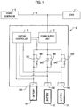
- the power device 1 is connected to a power line PL connected to a power generator G such as a photovoltaic generator and a load L such as various types of electric equipment.
- a power generator G such as a photovoltaic generator and a load L such as various types of electric equipment.
- a plurality of batteries E1, E2, andE3 (collectively referred to as a battery E) are detachably connected to the power device 1.
- the power device 1 safely and reliably performs installation/removal (hot swapping) of the battery E and charging/discharging of the battery E.
- the power device 1 is provided with connectors CN1, CN2, and CN3 (collectively referred to as a connector CN), a system controller 11, a power supply unit 12, bidirectional switches SA1, SA2, and SA3 (collectively referred to as a bidirectional switch SA), and unidirectional switches SB1, SB2, and SB3 (collectively referred to as a unidirectional switch SB).
- the connector CN is, for example, a receptacle connector. Each connector CN is provided with a connection terminal to which the battery E is detachably connected.
- the battery E includes, for example, a lithium-ion battery or a nickel-hydrogen battery.
- the battery E may be appropriately changed depending on where the power device 1 is applied.
- the battery E includes a single cell structure, a cell module formed by combining a plurality of cells, an electric device having a charge storage function, and the like.
- the system controller 11 includes a control unit 111, a first voltage detector 112, second voltage detectors 113a, 113b, and 113c (collectively referred to as a second voltage detector 113), a memory 114, a monitor 115, and an operating unit 116.
- the control unit 111 is provided with a central processing unit (CPU), a random access memory (RAM) serving as a main memory of the CPU, a timer, and the like.
- the control unit 111 is connected to the power supply unit 12, each bidirectional switch SA, each unidirectional switch SB, the first voltage detector 112, each second voltage detector 113, the memory 114, the monitor 115, and the operating unit 116 via a data line used to transmit commands or data to control each of them.
- control unit 111 When the power device 1 is powered on, the control unit 111 reads and executes a control program stored in the memory 114. As a result, the control unit 111 serves as the connection determiner 111a, the switch controller 111b, and the voltage controller 111c and executes a control process described below.
- the first and second voltage detectors 112 and 113 include voltage sensors or the like.
- the first voltage detector 112 is connected to the power line between the power supply unit 12 and the bidirectional switch SA.
- the first voltage detector 112 detects a voltage of this power line, that is, a voltage V0 of the power supply unit 12 side of the bidirectional switch SA.
- the voltage V0 detected by the first voltage detector 112 will be referred to as a first voltage.
- the first voltage detector 112 supplies a signal representing the first voltage to the control unit 111.
- the second voltage detector 113 is connected to the power line between the connector CN and the bidirectional switch SA.
- the second voltage detector 113 detects a voltage of this power line, that is, a voltage of the connector CN side of the bidirectional switch SA.
- the second voltage detector 113a is connected to the power line between the connector CN1 and the bidirectional switch SA1 to detect a voltage V1 of the connector CN1 side of the bidirectional switch SA1.
- the second voltage detector 113b detects a voltage V2 of the connector CN2 side of the bidirectional switch SA2.
- the second voltage detector 113c detects a voltage V3 of the connector CN3 side of the bidirectional switch SA3.
- the voltages V1, V2, and V3 detected by the second voltage detector 113 will be referred to as a second voltage.
- the second voltage detector 113 supplies a signal representing the second voltage to the control unit 111.
- the memory 114 includes a memory device such as a read-only memory (ROM) or a flash memory.
- the memory 114 stores a control program and data used by the control unit 111 to execute control processes described below, and various data generated or obtained by allowing the control unit 111 to execute various processes.
- the data used to execute the control processes described below includes data for controlling the bidirectional switch SA, the unidirectional switch SB, and the power supply unit 12.
- the memory 114 stores data used in control to turn on the bidirectional switch SA and turn off the unidirectional switch SB. This control is performed on the basis of whether or not the first and second voltages are equal to each other. This criterion is to determine whether or not the battery E has a chargeable/dischargeable state. If this criterion is satisfied (when the first and second voltages are equal to each other), the bidirectional switch SA is turned on, and the unidirectional switch SB is turned off.
- the memory 114 stores data used in control to turn off the bidirectional switch SA and turn on the unidirectional switch SB. This control is performed when the battery E is newly installed. In addition, the memory 114 stores data used to control the first voltage such that the first and second voltages become equal to each other. This control is also performed when the battery E is newly installed. Furthermore, the memory 114 stores data used in control to turn off both the bidirectional switch SA and the unidirectional switch SB. This control is performed when operation for instructing removal of the battery E is made.
- the memory 114 stores state data representing each state of the second voltage detector 113, the bidirectional switch SA, and the unidirectional switch SB.
- the control unit 111 detects the secondvoltage for each second voltage detector 113 by referring to the state data and updates and stores the detected second voltage.
- the control unit 111 controls the bidirectional switch SA and the unidirectional switch SB by referring to the state data.
- the ON/OFF states of the bidirectional switch SA and the unidirectional switch SB represented by the state data are sequentially updated and stored in the control unit 111.
- the memory 114 stores various display information displayed on the monitor 115. In addition, the memory 114 stores various setting information set on the basis of user's operation using the operating unit 116.
- the monitor 115 includes a display interface devices such as a liquid crystal display (LCD) and an organic electro-luminescence (EL) device.
- the monitor 115 displays, on a screen, various types of information such as a connection state of the battery E in each connector CN (presence/absence of the battery E), the first voltage detected by the first voltage detector 112, the second voltage detected by the second voltage detector 113, information representing whether or not charging or discharging can be performed (such as “chargeable/dischargeable state,” “dischargeable state,” and “non-chargeable/dischargeable state”), and a charging processing level (such as “under charging” or “charging completed”).
- the monitor 115 may be provided in positions corresponding to each connector CN to display various types of information corresponding to each connector CN.
- the operating unit 116 includes an input interface device for receiving user's operation.
- the operating unit 116 supplies the control unit 111 with an operation signal corresponding to the user's operation.
- the operating unit 116 receives, for example, operation for setting an initial value and upper and lower limits of the first voltage.
- the control unit 111 stores various types of setting information in the memory 114 in response to the user' s operation using the operating unit 116. Note that the operating unit 116 may be provided in each position corresponding to each connector CN.
- the power supplyunit 12 includes a power conditioner (power converter) such as a DC-AC inverter circuit, an AC-DC converter circuit, or a DC-DC converter circuit.
- the power supply unit 12 converts the AC power supplied from the power generator G into DC power and supplies the converted DC power to the battery E connected to the connector CN (for charging).
- the power supply unit 12 converts the DC power supplied (discharged) from each battery E into AC power and supplied the convertedACpower to the loadL.
- the power supply unit 12 receives, for example, apulsewidthmodulation (PWM) signal from the voltage controller 111c and supplies electric power in response to this signal.
- PWM pulsesewidthmodulation
- a resistor (pull-down resistor) of 1 k ⁇ may be arranged in the ground side of the power supply unit 12.
- the bidirectional switch SA is provided between the connector CN and the power supply unit 12.
- the bidirectional switch SA includes a switch circuit (bidirectional switch) such as a TRIAC (bidirectional thyristor), a metal-oxide semiconductor field effect transistor (MOSFET), an insulated gate bipolar transistor (IGBT), or a bipolar transistor.
- the bidirectional switch is implemented ina so-calledback-to-back manner in which, for example, sources of a pair of MOSFETs of the same channel are connected to each other.
- the bidirectional switch SA changes over between power supply and a power cut-off states bidirectionallybetween the power supplyunit 12 and the connector CN.
- bidirectional switch SA When the bidirectional switch SA is turned on, electric power is supplied bidirectionally between the power supply unit 12 and the connector CN (chargeable/dischargeable state). In contrast, when the bidirectional switch SA is turned off, electric power is cut off between the power supplyunit 12 and the connector CN (non-chargeable/dischargeable state).
- the unidirectional switch SB is provided between the connector CN and the power supply unit 12.
- the unidirectional switch SB is connected to the bidirectional switch SA in parallel.
- the unidirectional switch SB includes a switch circuit (unidirectional switch) such as a thyristor, a MOSFET, an IGBT, or a bipolar transistor.
- the unidirectional switch SB changes over between power supply and power cut-off states unidirectionally from the connector CN to the power supply unit 12.
- the unidirectional switch SB is turned on, power is supplied unidirectionally from the connector CN to the power supply unit 12 (only dischargeable state).
- the unidirectional switch SB is turned off, supply of power from the connector CN to the power supply unit 12 is cut off (non-dischargeable state).
- control process performed by the control unit 111 in the power device 1 configured in this manner will be described in brief.
- the control processes can be classified into a control process executed when the battery E is installed and a control process executed when the battery E is removed.
- the control process executed when the battery E is installed has a process of setting overall batteries E connected to the power device 1 to the "only-dischargeable” state and a process of setting all of the batteries E connected to the power device 1 to the "chargeable/dischargeable” state. Meanwhile, the control process executed when the battery E is removed has a process of setting the batteries E to the "non-chargeable/dischargeable” state.
- control process executed by the control unit 111 will be described with reference to FIGS. 4 and 5 .
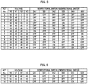
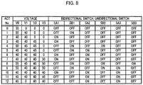
- a control process executed when the battery E1 is installed in the connector CN1 will be described by assuming that the battery E is not connected to any one of each connector CN of the power device 1 (Operation No. 0 in FIG. 5 ).
- connection determiner 111a periodically obtains a signal representing the first voltage from the first voltage detector 112 and sequentially updates and stores it. Inaddition, the connection determiner 111a periodically obtains a signal representing the second voltage from each second voltage detector 113 by referring to the state data of FIG. 3 . Furthermore, the connection determiner 111a updates and stores the second voltage detected by each second voltage detector 113.
- the switch controller 111b turns off the bidirectional switch SA and turns on the unidirectional switch SB corresponding to all of the connectors CN connected to the battery E (step S102). As a result, overall batteries E connected to the power device 1 are set to the dischargeable state.
- the switch controller 111b refers to the state data of FIG. 3 .
- the switch controller 111b turns off the bidirectional switch SA and turns on the unidirectional switch SB respectively corresponding to all of the second voltages exceeding a predetermined value (for example, 0 V), out of the second voltages.
- a predetermined value for example, 0 V
- the switch controller 111b turns off the bidirectional switch SA1 and turns on the unidirectional switch SB1 corresponding to the second voltage V1.
- the battery E1 connected to the connector CN1 becomes the dischargeable state. Note that, since the bidirectional switch SA is turned off in this state, the battery E is not charged, and the second voltage does not follow a change of the first voltage.
- the voltage controller 111c controls the first voltage using the power supply unit 12 on the basis of the second voltage (voltage of the battery E) determined to be installed with the battery E (step S103).
- the voltage controller 111c controls the first voltage such that the first and second voltages become equal to each other.
- step S104 If the switch controller 111b determines that there is no second voltage satisfying the criterion (NO in step S104), the voltage controller 111c returns to step S103 and controls the first voltage.
- the switch controller 111b turns on the bidirectional switch SA and turns off the unidirectional switch SB corresponding to the second voltage (step S105). For example, in Operation No. 2, the bidirectional switch SA1 is turned on, and the unidirectional switch SB1 is turned off corresponding to the second voltage V1. As a result, the battery E1 connected to the connector CN1 has the chargeable/dischargeable state.
- the switch controller 111b turns on the bidirectional switch SA and turns off the unidirectional switch SB for the group determined to satisfy the criterion. Note that, in this state (as the bidirectional switch SA is turned on), the second voltage becomes equal to the first voltage and follows a change of the first voltage.
- the switch controller 111b determines whether or not the bidirectional switches SA are turned on, and the unidirectional switches SB are turned off corresponding to all of the connectors CN connected to the battery E (step S106). That is, the switch controller 111b determines whether or not all of the connected batteries E have the chargeable/dischargeable state.
- the bidirectional switch SA1 is turned on, and the unidirectional switch SB1 is turned off corresponding to the connector CN1.
- the batteries E2 and E3 are not connected to the connectors CN2 and CN3, respectively (the second voltages V2 andV3 are set to zero) .
- the switch controller 111b determines that all of the connected batteries E have the chargeable/dischargeable state.
- step S106 If it is determined that all of the connected batteries E do not have the chargeable/dischargeable state (NO in step S106), the switch controller 111b returns to step S103 and performs the aforementioned process.
- step S106 if it is determined that all of the connected batteries E have the chargeable/dischargeable state (YES in step S106), the switch controller 111b returns to step S101. That is, in this case, a series of control processes for a case when the battery E is installed are completed.
- control process of steps S101 to S106 is also performed even when other batteries E2 and E3 are installed.
- connection determiner 111a turns off the bidirectional switches SA1 and SA2 and turns on the unidirectional switches SB1 and SB2 corresponding to the connectors CN1 and CN2, respectively, so that the batteries E1 and E2 are set to the dischargeable state (YES in step S101, and step S102).
- the battery E2 connected to the connector CN2 has the chargeable/dischargeable state.
- connection determiner 111a turns off the bidirectional switches SA1, SA2, and SA3 and turns on the unidirectional switches SB1, SB2, and SB3 corresponding to the connectors CN1, CN2, and CN3, respectively, so that the batteries E1, E2, and E3 are set to the dischargeable state (YES in step S101, and step S102).
- the voltage controller 111c increases the first voltage V0 up to 55 V such that the first voltage V0 becomes higher than the second voltage V3 (OperationNo. 8). Then, the voltage controller 111c decreases the first voltage V0 such that the first voltage V0 becomes equal to the second voltage V3.
- the battery E3 connected to the connector CN3 has the chargeable/dischargeable state.
- the battery E is installed in each connector CN.
- the connection determiner 111a determines whether or not the connector CN to remove the battery E is selected (step S107). For example, a user checks a connection state (presence/absence of the battery E) of each connector CN displayed on the monitor 115 and performs operation for selecting the connector CN to remove the battery E using the operating unit 116. Specifically, in Operation No. 11, if a user performs operation for selecting the connector CN1, the connection determiner 111a determines that the connector CN to remove the battery E is selected.
- connection determiner 111a If it is determined that the connector CN to remove the battery E is not selected in the process of step S107 (NO in step S107), the connection determiner 111a returns to step S101 and performs the same process as that described above.
- connection determiner 111a determines that the connector CN to remove the battery E is selected (YES in step S107)
- the switch controller 111b turns off both the unidirectional switch SB and the bidirectional switch SA corresponding to the selected connector CN (step S108).
- the connection determiner 111a notifies the monitor 115 of a fact that the battery E is removed. For example, in Operation No. 12, if a user removes the battery E1 from the connector CN1, the second voltage V1 becomes 0 V.
- the power device 1 maintains the bidirectional switch SA in the OFF state until the first voltage between the power supply unit 12 and the bidirectional switch SA and the second voltage between the connector CN and the bidirectional switch SA satisfy the criterion (become equal to each other).
- the bidirectional switch SA is turned on. That is, if the battery E is connected to the connector CN during the operation of the power device 1, the charging/discharging of the battery E is not performed until the first and second voltages satisfy the criterion. Meanwhile, if the criterion is satisfied, the bidirectional switch SA is controlled to perform charging/discharging. Using the power device 1, it is possible to safely and reliably perform installation/removal and charging/discharging of the battery E during the operation of the power device 1.
- this criterion may be appropriately and arbitrarily changed as long as it is recognized that the battery E has the chargeable/dischargeable state.
- a threshold value may be set for a voltage difference or ratio between the first and second voltages, and this threshold value may be used as a criterion to turn on the bidirectional switch SA and turn off the unidirectional switch SB.
- the first voltage is controlled such that the first and second voltages satisfy the criterion using the voltage controller 111c when a battery E is newly installed. As a result, it is possible to effectively set the newly installed battery E to the chargeable/dischargeable state.
- the unidirectional switch SB When the battery E is newly installed, the unidirectional switch SB is turned on. As a result, it is possible to supply (discharge) electric power unidirectionally from the connector CN to the power supply unit 12. Since the power device 1 can maintain the dischargeable state from the connected battery E, it is possible to take a countermeasure even when an unexpected voltage drop (such as an instantaneous interruption) occurs in external equipment (such as the power generator G or the load L).
- an unexpected voltage drop such as an instantaneous interruption
- the switch controller 111b turns on the bidirectional switch SA and turns off the unidirectional switch SB belonging to the group determined to satisfy the criterion.
- both the unidirectional switch SB and the bidirectional switch SA corresponding to the selected connector CN are turned off in response to the user's operation.
- the batteries E can be safely removed without performing this process. If a single battery E is removed while two or more batteries E are connected, the other battery E has low impedance. Therefore, the electric current flowing through the removed battery E flows to the other battery E. Consequently, no inrush current is generated between the removed battery E and the connector CN.
- the switch controller 111b receives removal of the battery E at any time, and the bidirectional switch SA and the unidirectional switch SB may not be turned off when the battery E is removed. Meanwhile, if a single battery E is connected, the switch controller 111b turns off the bidirectional switch SA and the unidirectional switch SB when the connector CN to remove the battery E is selected. As a result, it is possible to safely perform the removal even when only a single battery E is connected.
- the switch controller 111b may receive operation for selecting a group for which the charging is to be preferentially performed out of a plurality of groups and may preferentially charge the battery E corresponding to the group selected by a user.
- the switch controller 111b receives operation for selecting a group having the chargeable/dischargeable state.
- a user checks the state of the battery E for each group displayed on the monitor 115 and performs operation for selecting a group for which the charging is preferentially performed using the operating unit 116.
- the switch controller 111b turns on the bidirectional switches SA1 and SA2 and turns off the unidirectional switches SB1 and SB2 of the selected group.
- the switch controller 111b turns off the bidirectional switch SA3 and turns on the unidirectional switch SB3 of the non-selected group. That is, the batteries E1 and E2 belonging to the selected group are set to the chargeable/dischargeable state, and the battery E3 belonging to the non-selected group is set to the only dischargeable state.
- the voltage controller 111c controls the power supply unit 12 such that the power supply unit 12 performs charging until the batteries E1 and E2 corresponding to the selected group have a predefined voltage (for example, 55 V). As a result, it is possible to preferentially perform charging of the battery E corresponding to the group selected by a user.
- a predefined voltage for example, 55 V
- the switch controller 111b turns off both the bidirectional switches SA1 and SA2 and the unidirectional switches SB1 and SB2 of the corresponding group. As a result, it is possible to set the selected battery E in a non-chargeable/dischargeable state and safely remove the selected battery E. In addition, the switch controller 111b displays a fact that the charging is completed for the selected group on the monitor 115 to notify a user.
- the switch controller 111b turns on the bidirectional switch SA3 of the non-selected group and turns off the unidirectional switch SB3 so that the battery E3 corresponding to the non-selected group has the chargeable/dischargeable state.
- the voltage controller 111c may allow the power supply unit 12 to perform charging until the battery E3 corresponding to the non-selected group has a predefined voltage (for example, 55 V).
- the switch controller 111b may receive operation for setting a charging sequence and charge the battery E in order along the sequence set by a user.
- the switch controller 111b turns on the bidirectional switch SA and turns off the unidirectional switch SB corresponding to the connector CN connected to the charging target battery E in order along the sequence set by a user, so that the corresponding battery E has the chargeable/dischargeable state.
- the switch controller 111b turns off the bidirectional switch SA and turns on the unidirectional switch SB corresponding to the connector CN connected to the non-charging target battery E, so that the corresponding battery E has an only dischargeable state.
- the voltage controller 111c sequentially repeats a process of allowing the power supply unit 12 to perform charging in order along the sequence set by a user until the charging target battery E has a predefined voltage (for example, 55 V).
- the connection determiner 111a may determine whether or not its removal is allowed on the basis of the state of the load L. For example, the connection determiner 111a obtains a power consumption of the load L when the connector CN from which the battery E is removed is selected depending on user's operation. If the power consumption is higher than a threshold value, the connection determiner 111a locks the corresponding connector CN and inhibits removal of the battery E from the connector CN. Otherwise, if the power consumption is not higher than the threshold value, the connection determiner 111a unlocks the connector CN and allows the battery E to be removed from the connector CN.
- aswitchunit (including a bidirectional switch SA and a unidirectional switch SB) corresponding to a connector CN connected to a battery E is controlled on the basis of a relationship between a voltage (first voltage V0) of the power supply unit 12 side and a voltage (second voltages V1 to V3) of the connector CN side of the switch unit.
- a first relationship is established in advance for a case where the first voltage V0 is higher than the second voltage V1, V2, and V3. If first relationship is satisfied, the switch controller 111b turns off the bidirectional switch SA and turns on the unidirectional switch SB. That is, this control is performed on the basis of whether or not the first voltage is higher than the second voltage. If the bidirectional switch SA is turned off, and the unidirectional switch SB is turned on, the battery E connected to the connector CN corresponding to this switch unit has an only dischargeable state.
- the voltage controller 111c changes the first voltage V0 such that the first relationship is satisfied, that is, the first voltage V0 becomes higher than the second voltage.
- a second relationship is set in advance for a case where the first voltage V0 is equal to the second voltages V1, V2, and V3. If the second relationship is satisfied, the switch controller 111b turns on the bidirectional switch SA and turns off the unidirectional switch SB. That is, this control is performed on the basis of whether or not the first voltage is equal to the second voltage. If the bidirectional switch SA is turned on, and the unidirectional switch SB is turned off, the battery E connected to the connector CN corresponding to this switch unit has a chargeable/dischargeable state.
- the voltage controller 111c changes the first voltage V0 such that the second relationship is satisfied, that is, the first voltage V0 becomes equal to the second voltage.
- the switch controller 111b determines whether or not the first voltage V0 and the second voltage V1 corresponding to the connector CN1 satisfy a predetermined first relationship (step S112). If the first voltage V0 is higher than the second voltage V1, it is determined that the first relationship is satisfied. Otherwise, it is determined that the first relationship is not satisfied.
- the voltage controller 111c controls the power supply unit 12 such that the first relationship is satisfied by changing the first voltage V0 (step S113).
- the switch controller 111b controls the switch unit (including the bidirectional switch SA and the unidirectional switch SB) corresponding to the connector CN installed with the battery E such that the battery E has the only dischargeable state (step S114).
- the bidirectional switch SA1 changes over to OFF, and the unidirectional switch SB1 changes over to ON. In this manner, in Operation No.
- the switch controller 111b determines whether or not the first and second voltages satisfy a predetermined second relationship (step S115). If there is a second voltage equal to the first voltage V0, it is determined that the second relationship is satisfied. If there is no second voltage equal to the first voltage, it is determined that the second relationship is not satisfied. For example, in Operations Nos. 1, 4, and 8, there is no second voltage equal to the first voltage V0. Therefore, it is determined that the second relationship is not satisfied.
- the switch controller 111b turns on the corresponding bidirectional switch SA and turns off the corresponding unidirectional switch SB (stepS117) .
- the battery E installed in the connector CN corresponding to this switch unit has the chargeable/dischargeable state.
- the bidirectional switch SA1 satisfying the second relationship is turned on, and the unidirectional switch SB1 is turned off.
- the bidirectional switch SA2 satisfying the second relationship is turned on, and the unidirectional switch SB2 is turned off.
- the bidirectional switch SA3 satisfying the second relationship is turned on, and the unidirectional switch SB3 is turned off.
- the switch controller 111b determines whether or not the bidirectional switch SA is turned on, and the unidirectional switch SB is turned off (step S117) corresponding to each connector CN connected to the battery E. That is, the switch controller 111b determines whether or not the switch unit corresponding to each connected battery E is controlled.
- the battery E1 connected to the connector CN1 does not have the chargeable/dischargeable state.
- the batteries E1 and E2 connected to the connectors CN1 and CN2, respectively do not have the chargeable/dischargeable state (the bidirectional switch SA is not turned on, and the unidirectional switch SB is not turned off).
- the switch controller 111b determines that the switch unit is not controlled (NO in step S118). The switch controller 111b repeatedly performs the process of steps S115 to S118 until it is determined that the chargeable/dischargeable state is established.
- steps S119 and S120 are similar to that of steps S107 and S108 of the first embodiment.
- the switch unit (including the bidirectional switch SA and the unidirectional switch SB) is controlled such that electric power is supplied unidirectionally from the connector CN to the power supply unit 12.
- an unexpected voltage drop such as an instantaneous interruption
- the switch controller 111b controls the switch unit (including the bidirectional switch SA and the unidirectional switch SB) already having the chargeable/dischargeable state such that the battery E installed in the connector CN corresponding to this switch unit has the only dischargeable state when the first voltage V0 is changed.
- this control may not be performed. That is, the voltage controller 111c may change the first voltage V0 while the battery E is kept in the chargeable/dischargeable state.
- the second voltage V1 is changed to 50 V along with the first voltage V0.
- the second voltages V1 and V2 are changed to 55 V along with the first voltage V0. In this manner, the first voltage V0 may be changed while the switch unit (having the chargeable/dischargeable state) corresponding to the connector CN already connected to the battery E is kept in its state.
- the switch unit may include a pair of unidirectional switches provided to change over between power supply and power cut-off states only in different directions. That is, the switch unit corresponding to the connector CN may include a first switch provided to change over between power supply and power cut-off states unidirectionally from the power supply unit 12 to the connector CN, and a second switch connected in parallel with the first switch and provided to change over between power supply and power cut-off states unidirectionally from the connector CN to the power supply unit 12.
- the switch unit may include only the bidirectional switch SA or only the unidirectional switch SB.
- the numbers of connectors CN, the bidirectional switches SA, and the unidirectional switches SB may be changed arbitrarily.
- a commercially available power source may also be employed as an input power source of the power device 1 instead of the power generator G or along with the power generator G.
- the power device 1 may also be operated using the power of the battery E.
Landscapes
- Engineering & Computer Science (AREA)
- Power Engineering (AREA)
- Physics & Mathematics (AREA)
- General Physics & Mathematics (AREA)
- Chemical & Material Sciences (AREA)
- Electrochemistry (AREA)
- General Chemical & Material Sciences (AREA)
- Chemical Kinetics & Catalysis (AREA)
- Manufacturing & Machinery (AREA)
- Business, Economics & Management (AREA)
- Emergency Management (AREA)
- Charge And Discharge Circuits For Batteries Or The Like (AREA)
- Secondary Cells (AREA)
Priority Applications (1)
| Application Number | Priority Date | Filing Date | Title |
|---|---|---|---|
| PL17155586T PL3247021T3 (pl) | 2016-05-20 | 2017-02-10 | Urządzenie zasilające |
Applications Claiming Priority (2)
| Application Number | Priority Date | Filing Date | Title |
|---|---|---|---|
| JP2016101039 | 2016-05-20 | ||
| JP2017017681A JP6434070B2 (ja) | 2016-05-20 | 2017-02-02 | 電源装置 |
Publications (2)
| Publication Number | Publication Date |
|---|---|
| EP3247021A1 true EP3247021A1 (fr) | 2017-11-22 |
| EP3247021B1 EP3247021B1 (fr) | 2020-06-24 |
Family
ID=58017960
Family Applications (1)
| Application Number | Title | Priority Date | Filing Date |
|---|---|---|---|
| EP17155586.5A Active EP3247021B1 (fr) | 2016-05-20 | 2017-02-10 | Dispositif de puissance |
Country Status (3)
| Country | Link |
|---|---|
| US (1) | US10122208B2 (fr) |
| EP (1) | EP3247021B1 (fr) |
| PL (1) | PL3247021T3 (fr) |
Families Citing this family (4)
| Publication number | Priority date | Publication date | Assignee | Title |
|---|---|---|---|---|
| WO2017145316A1 (fr) * | 2016-02-25 | 2017-08-31 | 株式会社 東芝 | Installation de raccordement au réseau électrique |
| CA3059572C (fr) * | 2017-04-10 | 2023-04-04 | Vertiv Energy Systems, Inc. | Convertisseurs cc-cc ayant des bornes a balle |
| US11152663B2 (en) * | 2018-06-18 | 2021-10-19 | Datalogic Ip Tech S.R.L. | Advanced battery system |
| EP3981056B1 (fr) * | 2019-06-05 | 2023-05-24 | Blue Solutions | Dispositif et systeme rechargeables de stockage d'energie electrique, vehicule et installation munis d'un tel systeme |
Citations (6)
| Publication number | Priority date | Publication date | Assignee | Title |
|---|---|---|---|---|
| US20130181526A1 (en) * | 2010-10-15 | 2013-07-18 | Sanyo Electric Co., Ltd. | Power supply system |
| EP2670012A1 (fr) * | 2012-05-16 | 2013-12-04 | LG Electronics, Inc. | Dispositif de stockage d'énergie et procédé de commande de celui-ci |
| JP2014079139A (ja) * | 2012-10-12 | 2014-05-01 | Sharp Corp | 直流給電システム、および電気機器 |
| US20150022140A1 (en) * | 2012-04-26 | 2015-01-22 | Sekisui Chemical Co., Ltd. | Electricity storage system and cartridge |
| EP2980954A1 (fr) * | 2013-03-28 | 2016-02-03 | Sony Corporation | Dispositif de stockage de courant, système de stockage de courant et procédé de commande de dispositif de stockage de courant |
| EP2985857A1 (fr) * | 2013-04-12 | 2016-02-17 | Panasonic Intellectual Property Management Co., Ltd. | Système de gestion d'accumulateurs électriques et procédé de gestion d'accumulateurs électriques |
Family Cites Families (8)
| Publication number | Priority date | Publication date | Assignee | Title |
|---|---|---|---|---|
| JPH10341535A (ja) | 1997-04-08 | 1998-12-22 | Sony Corp | 電池パックおよびその制御方法、並びに記録媒体 |
| KR100536589B1 (ko) | 1999-07-27 | 2005-12-14 | 삼성전자주식회사 | 배터리 전원의 전자 장치 및 그의 전원 공급 제어 방법 |
| WO2013011758A1 (fr) | 2011-07-15 | 2013-01-24 | 日本電気株式会社 | Système accumulateur de stockage et procédé de commande de celui-ci |
| US20130076147A1 (en) | 2011-09-28 | 2013-03-28 | Fairchild Semiconductor Corporation | Multiple battery power path management system |
| JP5576467B2 (ja) | 2012-12-21 | 2014-08-20 | 積水化学工業株式会社 | 蓄電システム、及びカートリッジ |
| JP6005468B2 (ja) | 2012-10-10 | 2016-10-12 | シャープ株式会社 | パワーコンディショナ、その制御方法、および直流給電システム |
| JP2014103822A (ja) | 2012-11-22 | 2014-06-05 | Sharp Corp | 蓄電装置の電流制御装置 |
| JP6415218B2 (ja) | 2014-09-26 | 2018-10-31 | 株式会社日立情報通信エンジニアリング | 蓄電システム及び蓄電システムのプリチャージ方法 |
-
2017
- 2017-02-09 US US15/428,296 patent/US10122208B2/en active Active
- 2017-02-10 EP EP17155586.5A patent/EP3247021B1/fr active Active
- 2017-02-10 PL PL17155586T patent/PL3247021T3/pl unknown
Patent Citations (6)
| Publication number | Priority date | Publication date | Assignee | Title |
|---|---|---|---|---|
| US20130181526A1 (en) * | 2010-10-15 | 2013-07-18 | Sanyo Electric Co., Ltd. | Power supply system |
| US20150022140A1 (en) * | 2012-04-26 | 2015-01-22 | Sekisui Chemical Co., Ltd. | Electricity storage system and cartridge |
| EP2670012A1 (fr) * | 2012-05-16 | 2013-12-04 | LG Electronics, Inc. | Dispositif de stockage d'énergie et procédé de commande de celui-ci |
| JP2014079139A (ja) * | 2012-10-12 | 2014-05-01 | Sharp Corp | 直流給電システム、および電気機器 |
| EP2980954A1 (fr) * | 2013-03-28 | 2016-02-03 | Sony Corporation | Dispositif de stockage de courant, système de stockage de courant et procédé de commande de dispositif de stockage de courant |
| EP2985857A1 (fr) * | 2013-04-12 | 2016-02-17 | Panasonic Intellectual Property Management Co., Ltd. | Système de gestion d'accumulateurs électriques et procédé de gestion d'accumulateurs électriques |
Also Published As
| Publication number | Publication date |
|---|---|
| PL3247021T3 (pl) | 2020-10-19 |
| US10122208B2 (en) | 2018-11-06 |
| EP3247021B1 (fr) | 2020-06-24 |
| US20170338690A1 (en) | 2017-11-23 |
Similar Documents
| Publication | Publication Date | Title |
|---|---|---|
| TWI751229B (zh) | 控制裝置、控制系統、蓄電裝置以及電腦可讀取媒體 | |
| EP3327892B1 (fr) | Circuit de commande de charge et de décharge et bloc-batterie | |
| EP2517327B1 (fr) | Système de stockage d'énergie pour batterie doté d'une protection contre les courts-circuits, et procédé | |
| EP1897661A2 (fr) | Outil électrique | |
| EP3247021B1 (fr) | Dispositif de puissance | |
| AU2017200957B2 (en) | Power device | |
| CN104242374B (zh) | 充放电控制电路和电池装置 | |
| JP6370137B2 (ja) | 充放電制御回路及びバッテリ装置 | |
| JP2013537786A (ja) | 電池並列処理回路及び電池システム | |
| EP2843751A1 (fr) | Système de stockage d'énergie, dispositif de commande de stockage d'énergie et procédé de commande de stockage d'énergie | |
| CN112119563B (zh) | 蓄电系统 | |
| EP3514914A1 (fr) | Procédé de charge, dispositif de charge et système de charge | |
| CN104247200A (zh) | 充电控制设备和充电控制方法 | |
| US10177560B2 (en) | Battery monitoring device | |
| US11415632B2 (en) | Execution frequency setting device and execution frequency setting system | |
| US20190165604A1 (en) | Emergency dimming apparatus | |
| CN112400265A (zh) | 充放电装置以及用于管理电力储存部中的储存电力的方法 | |
| KR101364856B1 (ko) | 차량용 보조배터리 충전제어장치 및 그 충전제어방법 | |
| CN108377655B (zh) | 车载用电源装置 | |
| JP6343452B2 (ja) | 充電装置 | |
| KR20190071459A (ko) | 배터리 충전 시스템 및 이를 이용한 배터리 모듈의 최대용량 충전 제어방법 | |
| KR101483517B1 (ko) | Dc 전력 계통용 강압형 배터리 충방전 제어 장치 | |
| US20200412140A1 (en) | Storage battery unit | |
| KR20110066872A (ko) | 배터리 상태 감시 회로 및 배터리 장치 | |
| EP2482412B1 (fr) | Circuit de commande de commutation pour alimentation électrique, et circuit d'alimentation électrique |
Legal Events
| Date | Code | Title | Description |
|---|---|---|---|
| PUAI | Public reference made under article 153(3) epc to a published international application that has entered the european phase |
Free format text: ORIGINAL CODE: 0009012 |
|
| STAA | Information on the status of an ep patent application or granted ep patent |
Free format text: STATUS: REQUEST FOR EXAMINATION WAS MADE |
|
| 17P | Request for examination filed |
Effective date: 20170210 |
|
| AK | Designated contracting states |
Kind code of ref document: A1 Designated state(s): AL AT BE BG CH CY CZ DE DK EE ES FI FR GB GR HR HU IE IS IT LI LT LU LV MC MK MT NL NO PL PT RO RS SE SI SK SM TR |
|
| AX | Request for extension of the european patent |
Extension state: BA ME |
|
| GRAP | Despatch of communication of intention to grant a patent |
Free format text: ORIGINAL CODE: EPIDOSNIGR1 |
|
| STAA | Information on the status of an ep patent application or granted ep patent |
Free format text: STATUS: GRANT OF PATENT IS INTENDED |
|
| INTG | Intention to grant announced |
Effective date: 20200123 |
|
| GRAS | Grant fee paid |
Free format text: ORIGINAL CODE: EPIDOSNIGR3 |
|
| GRAA | (expected) grant |
Free format text: ORIGINAL CODE: 0009210 |
|
| STAA | Information on the status of an ep patent application or granted ep patent |
Free format text: STATUS: THE PATENT HAS BEEN GRANTED |
|
| AK | Designated contracting states |
Kind code of ref document: B1 Designated state(s): AL AT BE BG CH CY CZ DE DK EE ES FI FR GB GR HR HU IE IS IT LI LT LU LV MC MK MT NL NO PL PT RO RS SE SI SK SM TR |
|
| REG | Reference to a national code |
Ref country code: GB Ref legal event code: FG4D |
|
| REG | Reference to a national code |
Ref country code: CH Ref legal event code: EP |
|
| REG | Reference to a national code |
Ref country code: AT Ref legal event code: REF Ref document number: 1284839 Country of ref document: AT Kind code of ref document: T Effective date: 20200715 |
|
| REG | Reference to a national code |
Ref country code: DE Ref legal event code: R096 Ref document number: 602017018532 Country of ref document: DE |
|
| REG | Reference to a national code |
Ref country code: IE Ref legal event code: FG4D |
|
| REG | Reference to a national code |
Ref country code: SE Ref legal event code: TRGR |
|
| REG | Reference to a national code |
Ref country code: NL Ref legal event code: FP |
|
| REG | Reference to a national code |
Ref country code: NO Ref legal event code: T2 Effective date: 20200624 |
|
| PG25 | Lapsed in a contracting state [announced via postgrant information from national office to epo] |
Ref country code: LT Free format text: LAPSE BECAUSE OF FAILURE TO SUBMIT A TRANSLATION OF THE DESCRIPTION OR TO PAY THE FEE WITHIN THE PRESCRIBED TIME-LIMIT Effective date: 20200624 Ref country code: GR Free format text: LAPSE BECAUSE OF FAILURE TO SUBMIT A TRANSLATION OF THE DESCRIPTION OR TO PAY THE FEE WITHIN THE PRESCRIBED TIME-LIMIT Effective date: 20200925 Ref country code: FI Free format text: LAPSE BECAUSE OF FAILURE TO SUBMIT A TRANSLATION OF THE DESCRIPTION OR TO PAY THE FEE WITHIN THE PRESCRIBED TIME-LIMIT Effective date: 20200624 |
|
| REG | Reference to a national code |
Ref country code: LT Ref legal event code: MG4D |
|
| PG25 | Lapsed in a contracting state [announced via postgrant information from national office to epo] |
Ref country code: HR Free format text: LAPSE BECAUSE OF FAILURE TO SUBMIT A TRANSLATION OF THE DESCRIPTION OR TO PAY THE FEE WITHIN THE PRESCRIBED TIME-LIMIT Effective date: 20200624 Ref country code: RS Free format text: LAPSE BECAUSE OF FAILURE TO SUBMIT A TRANSLATION OF THE DESCRIPTION OR TO PAY THE FEE WITHIN THE PRESCRIBED TIME-LIMIT Effective date: 20200624 Ref country code: BG Free format text: LAPSE BECAUSE OF FAILURE TO SUBMIT A TRANSLATION OF THE DESCRIPTION OR TO PAY THE FEE WITHIN THE PRESCRIBED TIME-LIMIT Effective date: 20200924 Ref country code: LV Free format text: LAPSE BECAUSE OF FAILURE TO SUBMIT A TRANSLATION OF THE DESCRIPTION OR TO PAY THE FEE WITHIN THE PRESCRIBED TIME-LIMIT Effective date: 20200624 |
|
| REG | Reference to a national code |
Ref country code: AT Ref legal event code: MK05 Ref document number: 1284839 Country of ref document: AT Kind code of ref document: T Effective date: 20200624 |
|
| PG25 | Lapsed in a contracting state [announced via postgrant information from national office to epo] |
Ref country code: AL Free format text: LAPSE BECAUSE OF FAILURE TO SUBMIT A TRANSLATION OF THE DESCRIPTION OR TO PAY THE FEE WITHIN THE PRESCRIBED TIME-LIMIT Effective date: 20200624 |
|
| PG25 | Lapsed in a contracting state [announced via postgrant information from national office to epo] |
Ref country code: PT Free format text: LAPSE BECAUSE OF FAILURE TO SUBMIT A TRANSLATION OF THE DESCRIPTION OR TO PAY THE FEE WITHIN THE PRESCRIBED TIME-LIMIT Effective date: 20201026 Ref country code: CZ Free format text: LAPSE BECAUSE OF FAILURE TO SUBMIT A TRANSLATION OF THE DESCRIPTION OR TO PAY THE FEE WITHIN THE PRESCRIBED TIME-LIMIT Effective date: 20200624 Ref country code: AT Free format text: LAPSE BECAUSE OF FAILURE TO SUBMIT A TRANSLATION OF THE DESCRIPTION OR TO PAY THE FEE WITHIN THE PRESCRIBED TIME-LIMIT Effective date: 20200624 Ref country code: ES Free format text: LAPSE BECAUSE OF FAILURE TO SUBMIT A TRANSLATION OF THE DESCRIPTION OR TO PAY THE FEE WITHIN THE PRESCRIBED TIME-LIMIT Effective date: 20200624 Ref country code: IT Free format text: LAPSE BECAUSE OF FAILURE TO SUBMIT A TRANSLATION OF THE DESCRIPTION OR TO PAY THE FEE WITHIN THE PRESCRIBED TIME-LIMIT Effective date: 20200624 Ref country code: EE Free format text: LAPSE BECAUSE OF FAILURE TO SUBMIT A TRANSLATION OF THE DESCRIPTION OR TO PAY THE FEE WITHIN THE PRESCRIBED TIME-LIMIT Effective date: 20200624 Ref country code: SM Free format text: LAPSE BECAUSE OF FAILURE TO SUBMIT A TRANSLATION OF THE DESCRIPTION OR TO PAY THE FEE WITHIN THE PRESCRIBED TIME-LIMIT Effective date: 20200624 Ref country code: RO Free format text: LAPSE BECAUSE OF FAILURE TO SUBMIT A TRANSLATION OF THE DESCRIPTION OR TO PAY THE FEE WITHIN THE PRESCRIBED TIME-LIMIT Effective date: 20200624 |
|
| PG25 | Lapsed in a contracting state [announced via postgrant information from national office to epo] |
Ref country code: IS Free format text: LAPSE BECAUSE OF FAILURE TO SUBMIT A TRANSLATION OF THE DESCRIPTION OR TO PAY THE FEE WITHIN THE PRESCRIBED TIME-LIMIT Effective date: 20201024 Ref country code: SK Free format text: LAPSE BECAUSE OF FAILURE TO SUBMIT A TRANSLATION OF THE DESCRIPTION OR TO PAY THE FEE WITHIN THE PRESCRIBED TIME-LIMIT Effective date: 20200624 |
|
| REG | Reference to a national code |
Ref country code: DE Ref legal event code: R097 Ref document number: 602017018532 Country of ref document: DE |
|
| PG25 | Lapsed in a contracting state [announced via postgrant information from national office to epo] |
Ref country code: DK Free format text: LAPSE BECAUSE OF FAILURE TO SUBMIT A TRANSLATION OF THE DESCRIPTION OR TO PAY THE FEE WITHIN THE PRESCRIBED TIME-LIMIT Effective date: 20200624 |
|
| PLBE | No opposition filed within time limit |
Free format text: ORIGINAL CODE: 0009261 |
|
| STAA | Information on the status of an ep patent application or granted ep patent |
Free format text: STATUS: NO OPPOSITION FILED WITHIN TIME LIMIT |
|
| 26N | No opposition filed |
Effective date: 20210325 |
|
| PG25 | Lapsed in a contracting state [announced via postgrant information from national office to epo] |
Ref country code: SI Free format text: LAPSE BECAUSE OF FAILURE TO SUBMIT A TRANSLATION OF THE DESCRIPTION OR TO PAY THE FEE WITHIN THE PRESCRIBED TIME-LIMIT Effective date: 20200624 |
|
| PG25 | Lapsed in a contracting state [announced via postgrant information from national office to epo] |
Ref country code: MC Free format text: LAPSE BECAUSE OF FAILURE TO SUBMIT A TRANSLATION OF THE DESCRIPTION OR TO PAY THE FEE WITHIN THE PRESCRIBED TIME-LIMIT Effective date: 20200624 |
|
| GBPC | Gb: european patent ceased through non-payment of renewal fee |
Effective date: 20210210 |
|
| REG | Reference to a national code |
Ref country code: BE Ref legal event code: MM Effective date: 20210228 |
|
| PG25 | Lapsed in a contracting state [announced via postgrant information from national office to epo] |
Ref country code: LU Free format text: LAPSE BECAUSE OF NON-PAYMENT OF DUE FEES Effective date: 20210210 Ref country code: LI Free format text: LAPSE BECAUSE OF NON-PAYMENT OF DUE FEES Effective date: 20210228 Ref country code: CH Free format text: LAPSE BECAUSE OF NON-PAYMENT OF DUE FEES Effective date: 20210228 |
|
| PG25 | Lapsed in a contracting state [announced via postgrant information from national office to epo] |
Ref country code: IE Free format text: LAPSE BECAUSE OF NON-PAYMENT OF DUE FEES Effective date: 20210210 Ref country code: GB Free format text: LAPSE BECAUSE OF NON-PAYMENT OF DUE FEES Effective date: 20210210 |
|
| PG25 | Lapsed in a contracting state [announced via postgrant information from national office to epo] |
Ref country code: BE Free format text: LAPSE BECAUSE OF NON-PAYMENT OF DUE FEES Effective date: 20210228 |
|
| PG25 | Lapsed in a contracting state [announced via postgrant information from national office to epo] |
Ref country code: HU Free format text: LAPSE BECAUSE OF FAILURE TO SUBMIT A TRANSLATION OF THE DESCRIPTION OR TO PAY THE FEE WITHIN THE PRESCRIBED TIME-LIMIT; INVALID AB INITIO Effective date: 20170210 |
|
| PG25 | Lapsed in a contracting state [announced via postgrant information from national office to epo] |
Ref country code: CY Free format text: LAPSE BECAUSE OF FAILURE TO SUBMIT A TRANSLATION OF THE DESCRIPTION OR TO PAY THE FEE WITHIN THE PRESCRIBED TIME-LIMIT Effective date: 20200624 |
|
| PG25 | Lapsed in a contracting state [announced via postgrant information from national office to epo] |
Ref country code: MK Free format text: LAPSE BECAUSE OF FAILURE TO SUBMIT A TRANSLATION OF THE DESCRIPTION OR TO PAY THE FEE WITHIN THE PRESCRIBED TIME-LIMIT Effective date: 20200624 |
|
| PG25 | Lapsed in a contracting state [announced via postgrant information from national office to epo] |
Ref country code: TR Free format text: LAPSE BECAUSE OF FAILURE TO SUBMIT A TRANSLATION OF THE DESCRIPTION OR TO PAY THE FEE WITHIN THE PRESCRIBED TIME-LIMIT Effective date: 20200624 |
|
| PG25 | Lapsed in a contracting state [announced via postgrant information from national office to epo] |
Ref country code: MT Free format text: LAPSE BECAUSE OF FAILURE TO SUBMIT A TRANSLATION OF THE DESCRIPTION OR TO PAY THE FEE WITHIN THE PRESCRIBED TIME-LIMIT Effective date: 20200624 |
|
| PGFP | Annual fee paid to national office [announced via postgrant information from national office to epo] |
Ref country code: FR Payment date: 20251128 Year of fee payment: 10 Ref country code: NL Payment date: 20251215 Year of fee payment: 10 |
|
| PGFP | Annual fee paid to national office [announced via postgrant information from national office to epo] |
Ref country code: SE Payment date: 20251210 Year of fee payment: 10 |
|
| PGFP | Annual fee paid to national office [announced via postgrant information from national office to epo] |
Ref country code: PL Payment date: 20251128 Year of fee payment: 10 |
|
| PGFP | Annual fee paid to national office [announced via postgrant information from national office to epo] |
Ref country code: NO Payment date: 20260211 Year of fee payment: 10 Ref country code: DE Payment date: 20251216 Year of fee payment: 10 |