EP3247042B1 - Perforation de bits pour codes polaires - Google Patents
Perforation de bits pour codes polaires Download PDFInfo
- Publication number
- EP3247042B1 EP3247042B1 EP17171096.5A EP17171096A EP3247042B1 EP 3247042 B1 EP3247042 B1 EP 3247042B1 EP 17171096 A EP17171096 A EP 17171096A EP 3247042 B1 EP3247042 B1 EP 3247042B1
- Authority
- EP
- European Patent Office
- Prior art keywords
- bits
- bit
- polar
- coded bits
- input
- Prior art date
- Legal status (The legal status is an assumption and is not a legal conclusion. Google has not performed a legal analysis and makes no representation as to the accuracy of the status listed.)
- Active
Links
Images




Classifications
-
- H—ELECTRICITY
- H04—ELECTRIC COMMUNICATION TECHNIQUE
- H04L—TRANSMISSION OF DIGITAL INFORMATION, e.g. TELEGRAPHIC COMMUNICATION
- H04L1/00—Arrangements for detecting or preventing errors in the information received
- H04L1/004—Arrangements for detecting or preventing errors in the information received by using forward error control
- H04L1/0056—Systems characterized by the type of code used
- H04L1/0057—Block codes
- H04L1/0058—Block-coded modulation
-
- H—ELECTRICITY
- H03—ELECTRONIC CIRCUITRY
- H03M—CODING; DECODING; CODE CONVERSION IN GENERAL
- H03M13/00—Coding, decoding or code conversion, for error detection or error correction; Coding theory basic assumptions; Coding bounds; Error probability evaluation methods; Channel models; Simulation or testing of codes
- H03M13/03—Error detection or forward error correction by redundancy in data representation, i.e. code words containing more digits than the source words
- H03M13/05—Error detection or forward error correction by redundancy in data representation, i.e. code words containing more digits than the source words using block codes, i.e. a predetermined number of check bits joined to a predetermined number of information bits
- H03M13/13—Linear codes
-
- H—ELECTRICITY
- H03—ELECTRONIC CIRCUITRY
- H03M—CODING; DECODING; CODE CONVERSION IN GENERAL
- H03M13/00—Coding, decoding or code conversion, for error detection or error correction; Coding theory basic assumptions; Coding bounds; Error probability evaluation methods; Channel models; Simulation or testing of codes
- H03M13/27—Coding, decoding or code conversion, for error detection or error correction; Coding theory basic assumptions; Coding bounds; Error probability evaluation methods; Channel models; Simulation or testing of codes using interleaving techniques
- H03M13/2792—Interleaver wherein interleaving is performed jointly with another technique such as puncturing, multiplexing or routing
-
- H—ELECTRICITY
- H03—ELECTRONIC CIRCUITRY
- H03M—CODING; DECODING; CODE CONVERSION IN GENERAL
- H03M13/00—Coding, decoding or code conversion, for error detection or error correction; Coding theory basic assumptions; Coding bounds; Error probability evaluation methods; Channel models; Simulation or testing of codes
- H03M13/63—Joint error correction and other techniques
- H03M13/635—Error control coding in combination with rate matching
- H03M13/6362—Error control coding in combination with rate matching by puncturing
-
- H—ELECTRICITY
- H04—ELECTRIC COMMUNICATION TECHNIQUE
- H04L—TRANSMISSION OF DIGITAL INFORMATION, e.g. TELEGRAPHIC COMMUNICATION
- H04L1/00—Arrangements for detecting or preventing errors in the information received
- H04L1/004—Arrangements for detecting or preventing errors in the information received by using forward error control
- H04L1/0041—Arrangements at the transmitter end
-
- H—ELECTRICITY
- H04—ELECTRIC COMMUNICATION TECHNIQUE
- H04L—TRANSMISSION OF DIGITAL INFORMATION, e.g. TELEGRAPHIC COMMUNICATION
- H04L1/00—Arrangements for detecting or preventing errors in the information received
- H04L1/004—Arrangements for detecting or preventing errors in the information received by using forward error control
- H04L1/0056—Systems characterized by the type of code used
- H04L1/0067—Rate matching
- H04L1/0068—Rate matching by puncturing
-
- H—ELECTRICITY
- H04—ELECTRIC COMMUNICATION TECHNIQUE
- H04L—TRANSMISSION OF DIGITAL INFORMATION, e.g. TELEGRAPHIC COMMUNICATION
- H04L1/00—Arrangements for detecting or preventing errors in the information received
- H04L1/12—Arrangements for detecting or preventing errors in the information received by using return channel
- H04L1/16—Arrangements for detecting or preventing errors in the information received by using return channel in which the return channel carries supervisory signals, e.g. repetition request signals
- H04L1/18—Automatic repetition systems, e.g. Van Duuren systems
- H04L1/1812—Hybrid protocols; Hybrid automatic repeat request [HARQ]
- H04L1/1819—Hybrid protocols; Hybrid automatic repeat request [HARQ] with retransmission of additional or different redundancy
Definitions
- the present invention relates to a method according to the pre-characterizing part of claim 1 and to an apparatus according to the pre-characterizing part of claim 4. Such method and apparatus are shown in document US 2015/0333769 A1 .
- Document EP 2 722 993 A1 discloses that in each of the blocks S2_1 to S2_N2 of a second stage of a polar graph, a first code word bit may be selected as a puncturing bit. Therein, the first code word bits of the blocks S2_1 to S2_N2 of the second stage are connected to the input word bits of the blocks S1_1 to S1_N1 of a first stage of the polar graph. That is, in the second stage, locations of puncturing bits may be periodic. Document EP 2 722 993 A1 further discloses that the second code word bits of the blocks S2_1 to S2_N2 of the second stage may also be selected as puncturing bits. Therein, the second code word bits of the blocks S2_1 to S2_N2 of the second stage are connected to the input word bits of a second block S1_2 of the blocks S1_1 to S1_N1 of the first stage.
- Polar codes are a class of error correcting codes, and can be employed to achieve the capacity of various communication channels. Construction of polar codes relies on a specific recursive encoding procedure. The recursive encoding procedure synthesizes a set of virtual channels from a plurality of usages of a transmission channel. The synthesized virtual channels tend to become either noiseless or completely noisy when the code length goes to infinity. This phenomenon is known as channel polarization. In their original construction, polar codes only allow code lengths that are powers of two. Puncturing techniques can be employed to modify polar codes in order to achieve any code length. In puncturing, one or more coded bits are selected and not transmitted.
- aspects of the disclosure provide an apparatus for polar code puncturing according to claims 4 to 6.
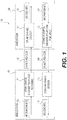
- Fig. 1 shows a wireless communication system 100 according to an embodiment of the disclosure.
- the wireless communication system 100 includes a mobile device 110 and a base station 120.
- the mobile device 110 includes an uplink (UL) channel encoder 111 and a downlink (DL) channel decoder 112.
- the base station 120 includes an UL channel decoder 121 and a DL channel encoder 122. Those components are coupled together as shown in Fig. 1 .
- the wireless communication system 100 is a mobile communication network compliant with one of various wireless communication standards, for example, developed by the 3rd Generation Partnership Project (3GPP).
- the mobile device 110 can be a mobile phone, a lap top computer, a tablet computer, and the like.
- the base station 120 can include one or more antennas. The antennas can be employed to receive or transmit wireless signals to communicate with a plurality of mobile devices including the mobile device 110. Accordingly, the based station 120 can receive data from the mobile device 110 and transfer the data to another mobile device or another communication network, or vice versa.
- the UL channel encoder 111 at the mobile device 110 is configured to perform channel coding with polar codes for transmission of control information from the mobile device 110 to the base station 120.
- the control information can be uplink control information generated at a physical layer or an upper layer of a protocol stack of the mobile device 110.
- blocks of uplink control information are each encoded into a polar code.
- the UL channel encoder 111 is configured to employ polar code puncturing techniques described in this disclosure to adjust lengths of the polar codes in order to match coded bits with allocated transmission resources.
- the transmission resources can be resource elements in a time-frequency resource grid of an orthogonal frequency division multiplexing (OFDM) modulation system.
- the UL channel decoder 121 at the base station 120 is configured to perform channel decoding as a counterpart of the UL channel encoder 111.
- the mobile device 110 In operation, the mobile device 110 generates control information, such as the uplink control information, and performs a channel coding process for transmission of the control information.
- control information such as the uplink control information
- a block of information bits 113 of the control information can be received at the UL channel encoder 111.
- the UL channel encoder 111 can then employ a polar encoder to encode the block of information bits 113 into a polar code.
- the UL channel encoder 111 can employ the polar code puncturing techniques to extract a certain number of coded bits from the polar code according to allocated transmission resources.
- a punctured code 132 resulted from the puncturing operation can then be obtained and transmitted to the base station 120.
- the punctured code 132 can be received and processed, and decoded bits 123 corresponding to the information bits 113 can accordingly be generated.
- the DL channel encoder 122 at the base station 120 and the DL channel decoder 112 at the mobile device 110 have similar functions and structures as the UL channel encoder 111 and the DL channel decoder 121, respectively, however, operating in an opposite direction.
- a block of information bits 124 can be generated at the base station 120 and encoded into a polar code at the DL channel encoder 122.
- a punctured code 134 can be extracted from the polar code.
- the punctured code 134 can then be received and processed at the DL channel decoder 112. Accordingly, decoded bits 114 corresponding to the information bits 124 can be obtained.
- Fig. 2 shows an apparatus 200 for rate matching according to an embodiment of the disclosure.
- the apparatus 200 employs the polar code puncturing techniques to modify polar codes to generate punctured codes in order to match coded bits with allocated transmission resources. Functions and processes described with reference to the apparatus 200 can be utilized in the mobile device 110 or the base station 120 in the Fig. 1 example for transmission of uplink or downlink control information.
- the apparatus 200 includes a channel encoder 240 and a modulator 230.
- the channel encoder 240 includes a polar encoder 210 and a rate matching module 220.
- the rate matching module 220 includes a puncture controller 222 and a bit selector 224. Those components are coupled together as shown in Fig. 2 .
- the apparatus 200 can be a mobile device, or a base station.
- the apparatus 200 can be configured to transmit data to a remote device, such as a mobile device or base station, through a wireless channel.
- the channel encoder 240 is configured to perform a channel coding process to encode to-be-transmitted data.
- the modulator 230 is configured to further process the encoded data to generate modulated signals. For example, interleaving, quadrature amplitude modulation (QAM) or quadrature phase shift keying (QPSK) modulation, antenna mapping, transmission resource mapping, and the like, can be performed at the modulator 230.
- the modulated signal can subsequently be transmitted to a remote device.
- the polar encoder 210 is configured to encode information bits 201 into polar codes.
- polar codes can be constructed based on a specific recursive encoding procedure.
- a set of N virtual channels can be synthesized from N usages of a transmission channel W, where N denotes the code length of the polar codes.
- a successive cancellation (SC) decoder for example, can be employed to reverse the recursive encoding procedure at a receiver end.
- SC successive cancellation
- the former bit channels can be referred to as good channels, while the latter bit channels can be referred to as bad channels.
- an encoding strategy is to transmit information bits over the good channels while assigning fixed bit (referred to as frozen bits) to the bad channels.
- reliabilities of the number of N bit channels can be calculated based on a channel condition of the transmission channel W. Based on the calculated reliabilities, the most reliable bit channels can be used for transmission of information bits while the least reliable bit channels can be set to a fixed value, for example, zero.
- a polar code can be obtained by applying a linear transformation on a data vector (input bits vector) that contains both information bits and frozen bits.
- G N is a square matrix and represents a generator matrix of the polar codes.
- each input bit and the respective input bit index correspond to a row in the generator matrix G N .
- each bit channel or synthesized channel corresponds to a row in the generator matrix G N .
- each input bit corresponds to a bit channel.
- the input bit indices are also used for indexing the bit channels and the rows in the generator matrix in this detailed description.
- positions for information bits and frozen bits among the input bits positions can first be determined. For example, reliabilities of bit channels for the polar encoding process can first be determined. The reliabilities can be calculated on line based on an estimated channel condition. Alternatively, reliabilities can be calculated off line for different channel conditions and stored in a memory, and retrieved according to a current estimated channel condition. In addition, the polar encoder 210 can receive a P number of frozen bit positions 204 determined at the rate matching module 220. Each of the received frozen bit positions can correspond to a punctured coded bit.
- the polar encoder 210 can then exclude the P frozen bit positions from the N input bits positions. Subsequently, the polar encoder 210 can select K positions among the left N-P input bits positions for information bits. The selected K positions correspond to bit channels having the highest reliabilities among bit channels corresponding to the left N-P input bits positions. Finally, the left N-P-K input bits positions can be determined to be the fixed bits position.
- the polar encoder 210 can map the information bits to the input vector of the polar encoder 210. Subsequently, the input vector can be encoded into a polar code 202 based on a generator matrix G N .
- the polar code 202 has a length of N, and is later punctured at the rate matching module 220. Accordingly, the polar code 202 is referred to as a mother polar code or a mother code 202, and a code generated from the mother code 202 after the puncturing operation is referred to as a punctured code.
- the code length N of the mode code 202 is referred to as a mother code length.
- the rate matching module 220 receives the mother code 202 and performs a puncturing process to generate a punctured code 203.
- the puncture controller 222 is configured to determine to-be-punctured bit positions 205 in the mother code 202. In one example, the determination process is based on the generator matrix G N , the mother code length N, and a punctured code length M. In one example, the punctured code length M is determined at a component in the apparatus 200, for example, according to a channel condition of the transmission channel or allocation of transmission resources. In addition, the puncture controller 222 is also configured to determine the frozen bit positions 204. For polar codes, puncturing operations can affect reliabilities of bit channels.
- the input bit can be determined to be a frozen bit among input bits.
- the bit selector 224 is configured to receive the mother code 202 and extract un-punctured bits from the mother code 202 to form the punctured code 203. The extraction can be based on information of to-be-punctured bit positions 205 received from the puncture controller 222.
- the to-be-punctured bit position information is represented as a puncture pattern.
- the puncture pattern can be expressed by a binary vector. For example, zeros in the puncture pattern vector can represent punctured bits positions, while ones can represent un-punctured bits positions. Further details of functions and structures of the rate matching module 220 are described below.
- the rate matching module 220 in Fig. 2 example employs a puncturing scheme to realize rate matching functionality
- the rate matching module 220 can employ more than one rate matching schemes to optimize its rate matching performance.
- the rate matching module 220 can select one rate matching scheme from multiple rate matching schemes, such as puncturing, shortening, repetition, and the like. The selection can be based on some conditions, such as whether mother code rate, defined as a ratio of information bits length to a polar code length, is larger than a threshold, whether the mother code length is larger than a code length required by a transmission resource allocation, and the like.
- different rate matching schemes can be selected to achieve an optimal rate matching performance.
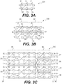
- Figs. 3A-3C show a recursive construction process for constructing a polar graph 300C which is not used in the invention.
- a polar graph constructed according to a generator matrix can be used as a tool for analysis of encoding and puncturing processes conducted based on the generator matrix.
- the polar graph 300A includes two input bits u0 and ul, represented by two circle 321-322, and two output bits x0 and x1, represented by two circles 341-342.
- the polar graph 300A can illustrate a channel polarization process.
- squares 301 and 302 can represent two virtual bit channels, an upper channel 301 and a lower channel 302, corresponding to the encoding process.
- the input bit u0 is transmitted through the upper channel 301; however, the transmission of u0 is interfered by the input bit u1. Accordingly, reliability of the upper channel 301 for transmission of the input bit u0 is decreased.
- the input bit u1 is transmitted via the lower channel 302, however, the transmission of u1 is assisted by the upper channel 301 because part of u1 is transmitted via the upper channel 301. As a result, the upper channel 301 is degraded while the lower channel 302 is enhanced.
- the polar graph 300B includes four input bits u0-u3, and four output bits x0-x3.
- the polar graph 300B uses the polar graph 300A as a building block for constructing the polar graph 300B.
- the polar graph 300B includes a first stage 361 and a second stage 362.
- Each stage 361-362 includes an upper block 371 or 373 and a lower block 372 or 374, respectively.
- the first stage upper block 371 uses upper channels of the second stage 362, while the first stage lower block 372 uses lower channels of the second stage 362.
- four bit channels are formed by the flowing four pairs of sub-bit channels shown in Fig. 300B: a first bit channel 303-307, a second bit channel 304-309, a third bit channel 305-308, and a fourth bit channel 306-310.
- the bit channel of 303-307 is the noisiest because the two bit channels 303 and 307 are worse bit channels in the respective blocks 371 or 373, while the bit channel of 306-310 is the most reliable because the two bit channels 306 and 310 are better bit channels in the respective blocks 372 or 374.
- Reliabilities of the other two bit channels, 304-309 and 305-308 are between that of the two bit channels, 303-307 and 306-310.
- the polar graph 300C includes eight input bits u0-u7 and eight output bits x0-x7.
- the polar graph 300C illustrates an encoding process corresponding to the generator G 8 .
- the polar graph 300C uses the polar graphs 300A and 300B as building blocks for constructing the polar graph 300C.
- the polar graph 300C includes a first stage 363 and a second stage 364.
- the stage 363 includes an upper block 375 and a lower block 376, while the stage 364 includes four blocks 377-380.
- the first stage upper block 375 uses upper channels of the second stage 364, while the first stage lower block 376 uses lower channels of the second stage 364.
- bit channels are formed. For example, one of the eight bit channels is formed by concatenating three sub-bit channels 311, 312 and 313. Another one of the eight bit channels is formed by concatenating three sub-bit channels 314, 315 and 316. Each of the eight bit channels initiates from an input bits and ends at an output channel. Accordingly, an input bit associated with the respective bit channel is used for referring the respective bit channel. For example, the bit channel of 311-312-313 starts from the input bits u1, thus is referred to as bit channel u1.
- a bit-reversed index of an output bit is the index of an input bit that is directly connected to this output bit.
- binary indices of the output bits x0-x7 are shown in column 391
- bit-reversed indices of the output bits x0-x7 are shown in column 392
- binary indices of the input bits u0-u7 are shown in column 393.
- the output bit x4 has a binary index 100.
- the bit-reversed index of the output bit x4 is 001 which is the index of the input bit u1.
- the input bit u1 is directly connected to the output bit x4 via the bit channel u1. Accordingly, given an input bit, by performing a bit-reversal operation on the index of this input bit, an index of an output bit directly connected to this input bit can be determined.
- the bit channels u0-u7 have polarized properties due to the polarization effect.
- upper bit channels associated with input bits near the top of the polar graph have worse reliabilities while lower bit channels associated with input bits near the bottom of the polar graph have better reliabilities.
- the lower bit channels' positions in the polar graph the better the reliabilities of those bit channels.
- the lower input bits are preferred to be used as information bits while the upper input bits are used as frozen bits.
- An input bit used as an information bit is referred to as a good bit while an input bit used as a frozen bit is referred to as a bad bit.
- good bits are shown with circles shaded with cross lines, while bad bits are shown with circles shaded with up-ward diagonal lines.
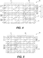
- Fig. 4 shows a polar graph 400 illustrating a first conventional puncturing strategy.
- the polar graph 400 is similar to the polar graph 300C in Fig. 3C .
- the polar graph 400 includes a first stage 401 and a second stage 402.
- the second stage 402 includes a sequence of output blocks 421-424.
- the polar graph 400 includes eight input bits u0-u7, and eight output bits x0-x7. Eight bit channels u0-u7 connect the eight pairs of input bits and output bits, respectively.
- the first conventional puncturing strategy is to puncture output bits at upper output blocks first. For example, for different length of to-be-punctured bits, P, the output bits are punctured in a top-down order from the top bits x0 until the P-th output bits.
- This first conventional puncturing strategy confines the puncturing impact to upper channels at the input side of the first stage blocks.
- the to-be-punctured bit length P equals 4, and accordingly the output bits x0-x3 are selected and punctured.
- the input bits u0, u2, u4, and u6, which are directly connected to the punctured output bits x0, x2, x1 and x3, respectively, through the bit channels u0, u2, u4, and u6, are impacted.
- the punctured bits are not transmitted, the bit channels corresponding to the punctured bits become unusable. Consequently, the input bits u0, u2, u4, and u6 cannot be decoded and are used as frozen bits.
- a puncturing ratio is defined as the ratio of a punctured bits length to a mother polar code length.
- SNR signal-to-noise ratio
- a low code rate the ratio between input bits length and punctured code length
- the low code rate adopted can be 1/5, 1/3, or 2/5.
- a number of information bits is relative fewer than with a high code rate, and good bit channels become critical for reliable transmission of the information bits. Therefore, performance of this first conventional puncturing strategy may suffer from early good bit loss leading to inferior performance for low code rate transmission.
- Fig. 5 shows a polar graph 500 illustrating a second conventional puncturing strategy.
- the polar graph 500 is equivalent to the polar graph 300C in Fig. 3C in terms of property of polar codes constructed from the polar graphs 500 or 300C.
- a bit-reversed index of an output bit would be an index of an input bit that is directly connected to the output bit through a bit channel.
- the polar graph 500 includes a first stage 501 and a second stage 502.
- the second stage 502 includes two output blocks 521-522.
- the polar graph 500 includes eight input bits u0-u7, and eight output bits x0-x7. Eight bit channels u0-u7 connect the eight pairs of input bits and output bits, respectively.
- the second conventional puncturing strategy is to first puncture from upper output bits of each output blocks 521-522 of the second stage 502 and go down to lower output bits of each output blocks 521-522 until reaching the length of to-be-punctured bits. Accordingly, input bits positions mirroring positions of the punctured output bits are impacted by the puncturing operation. For example, when the output bits x0, x1, x4, and x5 are punctured, the input bits u0, u1, u4 and u5 are impacted.
- the second conventional puncturing strategy preserves good bits close to the bottom of the polar graph.
- puncturing of good bits degrades the coding performance of the second conventional puncturing strategy.
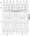
- Fig. 6 shows a polar graph 600 illustrating an example of a first polar code puncturing technique which is not part of the invention.
- a mother polar code length corresponding to the polar graph 600 is 16.
- the polar graph 600 includes sixteen input bits u0-u15 and sixteen output bits x0-x15.
- the polar graph 600 includes an input stage 601 and an output stage 602.
- the input stage 601 includes two input blocks 611-612.
- the output stage 602 includes a sequence of output blocks 621-628.
- Fig. 6 also shows binary indices 613 of the input bits besides the input bits and binary indices 614 of the output bits beside the output bits.
- a strategy for the first puncturing technique is to consider impacts at both input bit side and output bit side when selecting to-be-punched bit channels.
- a bit channel connected to a to-be-punctured output bit is referred to as a to-be-punctured bit channel
- an input bit connected to a to-be-punctured bit channel is referred to as a to-be-punctured input bit.
- the strategy of the first puncturing technique can include: at the output bit side, preferably selecting to-be-punctured output bits that are positioned at upper channels of upper output blocks, while at the input bit side, preferably selecting upper input bits as to-be-punctured input bits.
- a to-be-punctured bits length is P.
- a puncturing process implementing the first polar code puncturing technique can include the following steps:
- a first portion of 2 q to-be-punctured output bits can be determined.
- a number of the first portion of 2 q to-be-punctured output bits is 4.
- the input bits corresponding to the index set A are u0-u3.
- the to-be-puncture output bits can be determined to be x0, x8, x4, and x12, respectively.
- a second portion of the remaining p to-be-punctured output bits can be determined.
- Each element of the index set B equals a sum of 2 q and one of a q-bit bit reversal of 0, ..., (p-1).
- the q-bit bit reversal of 0, ..., (p-1) is the 2-bit bit reversal of ⁇ 00, 01 ⁇ , or in the bit-reversed form, ⁇ 00, 10 ⁇ .
- indices of the second portion of p to-be-punctured output bits can be determined to be ⁇ 0010, 0110 ⁇ corresponding to the output bits x2 and x6.
- the input bits having indices included in the index set A U B can be determined to be frozen bits.
- Figs. 7A-7C show a comparison of block error rate (BLER) performance of different puncturing approaches resulted from a simulation experiment.
- BLER block error rate
- Each vertical axis represents the BLER
- each horizontal axis represents SNR of a transmission channel for transmitting the punctured polar codes.
- solid lines represent performance of the first conventional puncturing strategy described with reference to Fig. 4 .
- Dotted lines represent performance of the second conventional puncturing strategy described with reference to Fig. 5 .
- Dashed lines represent performance of the first puncturing technique described with reference to Fig. 6 .
- Fig. 7A shows two diagrams at the right side and left side each corresponding to a high code rate, 5/6 and 8/9, respectively.
- the performance of the first technique (dashed line) is better than the conventional puncturing strategies for high code rate polar code encoding.
- Fig. 7B shows performance of the three methods at three different medium code rates, 1/2, 2/3, 3/4.
- the performance of the first technique (dashed line) is better than the conventional puncturing strategies for medium code rate polar code encoding.
- Fig. 7C where performance at three different low code rates, 1/5, 1/3, 2/5, is shown, the first technique (dashed line) demonstrates moderate performance compared with the conventional puncturing strategies.
- Fig. 8 shows a polar graph 800 illustrating an example of a second polar code puncturing technique which is not part of the invention.
- the polar graph 800 is the same as the polar graph 600.
- the second puncturing technique solves the low performance issue of the first puncturing technique shown in Fig. 7C when low code rate is employed.
- the output bit x6 is punctured.
- puncturing x6 will degrade reliability of the bit channel 801. Consequently, error probabilities for decoding the good input bits u14 and u15 can be increased.
- input bits close to the bottom of the polar graph are used as information bits.
- puncturing the output bit x6 can impact performance of low code rate transmission.
- a position of a to-be-punctured input bit can be moved downward from the position of u6 to the position of u8.
- the to-be-punctured output bit corresponding to u8 is x1. Puncturing of x1 has no significant effect on good bits located close to the bottom of the polar graph 800.
- a puncturing process implementing the second technique can include the following steps:
- the same operation as the first step of the first puncturing technique can be performed to determine a first portion of the to-be-punctured output bits.
- the input bits u0-u3 can be determined to be the to-be-punctured input bits, and accordingly the output bits x0, x4, x8, x12 are determined to be punctured.
- the first part of the index set B' includes p/2 number of input bits indices and corresponds to input bits adjacent to the to-be-punctured input bits u0-u3.
- the second part of the index set B', ⁇ 2 n-1 + 0, 2 n-1 + 1, ..., 2 n-1 + (p/2-1) ⁇ includes the other p/2 number of input bits indices and corresponds to input bits starting from the input bit of index 2 n-1 and going downwards.
- a floor or ceiling function can be employed to map p/2 to a closest integer.
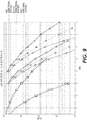
- Fig. 9 shows a comparison of BLER performance of different puncturing approaches resulted from a simulation experiment.
- Fig. 9 is similar to Fig. 7C where low code rate performance of the first and second conventional puncturing strategies is shown.
- the dashed lines represent performance of the second puncturing technique described with reference to Fig. 8 .
- the performance of the second puncturing technique has been improved being stronger than the first and second conventional puncturing strategies.
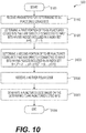
- Fig. 10 shows a process 1000 for polar code puncturing which is not part of the invention
- the process 1000 can be performed by the channel encoder 240 in Fig. 2 example.
- the process 1000 starts from S1001, and proceeds to S1010.
- a set of parameters for determining to-be-punctured coded bits in a mother polar code can be received, for example, at the puncture controller 222 in Fig. 2 .
- the parameters can also include information of a generator matrix G N for generating mother polar codes. Based on the information of the generator matrix connection relationships via bit channels between input bits and output bits of the polar graph can be determined.
- a first portion of to-be-punctured coded bits is determined based the parameters, for example, by the puncture controller 222.
- the first portion of to-be-punctured coded bits is coded bits directly connected to input bits having the lowest indices.
- Directly connection between an input bit and an output bit in the polar graph means the input bit and the output bit are connected via a virtual bit channel of the polar graph.
- a second portion of to-be-punctured coded bits can be determined for example, by the puncture controller 222.
- p/2 to-be-punctured bits are coded bits directly connected to p/2 input bits that are distributed in a partition of input bits having indices starting from N/2.
- Elements in the first part of the index set B, ⁇ 2 q + (0, ..., p/2-1) ⁇ , are the input bits adjacent to the first portion of to-be-punctured coded bits determined at S1020.
- the input bits of the first part of the index set B have indices in ⁇ N/4+ (0, ..., p/2-1) ⁇ , while the input bits of the second part of the index set B have indices in ⁇ N/2+ (0, ..., p/2-1) ⁇ . Accordingly, the 2 q input bits corresponding to the 2 q to-be-puncture output bits are included in the first one-fourth of the N input bits, while the input bits of the first and second parts of the index set B are distributed in the second and third one-fourth of the N input bits.
- a mother code with length N generated from a polar encoder can be received, for example, at the bit selector 224 in Fig. 2 .
- the mother code can be stored in a buffer.
- a punctured code can be generated based on results of determinations at S1020 and S1030.
- position information can be received from the puncture controller 222.
- the position information can be in the form of a sequence of indices indicating the to-be-punctured bits.
- the position information can be in a form of a binary pattern vector using zeros and ones indicating positions to be punctured.
- the bit selector 224 can exclude the un-punctured bits from the mother code to output a punctured code.
- the process 1000 proceeds to S1099, and terminates at S1099.
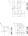
- Figs. 11A-11C show a recursive construction process for construction of a second type of polar graphs as used in the present invention.
- the second type of polar graphs can be based on a second type of generator matrices.
- the structure of the polar graph 1100A is similar to the polar graph 300A in Fig. 3A .
- the element 1101 represents a modulo-2 addition of two input bits u0-u2.
- Two virtual bit channels 1102 and 1103 are formed between two pairs of input bits and output bits: one between u0 and x0, and the other between u1 and x1.
- the two bit channels 1102-1103 are included in a combined channel W2.
- the combined channel W2 combines two usages of a transmission channel for transmissions of x0 and x1 independently.
- the polar graph 1100B is constructed based on the polar graph 1100A.
- Two W2 channels are further combined to form a W4 combined channel.
- Four bit channels 1104-1107 are formed.
- the bit channels in Fig. 11B are positioned horizontally. Accordingly, indices of an input bit and an output bit connected by a bit channel in the polar graph are the same.
- Fig. 11C shows how a N-dimensional polar graph 1100C can be constructed based on combined channels of W N/2 .
- the second type of polar graphs and generator matrices is equivalent to the first type of polar graphs and generator matrices in terms of property of polar codes generated respectively.
- the difference between the two types of coding manners is that for a same set of input bits, two sequences of output bits generated by the two types of encodings are arranged in a different order. Specifically, performing a bit-reversal permutation operation to one output sequence results in the other output sequence.
- the polar code puncturing techniques described with reference to the first type of polar graphs are also applicable to polar graphs of the second type.
- to-be-punctured coded bits are determined with reference to indices of input bits that are directly connected to the to-be-punctured coded bits.
- reasoning for selection of those input bits is independent of what types of polar graphs are employed.
- using input bit indices to describe puncturing selections is a universal way over the two types of polar graphs.
- an output bit which is directly connected to the input bit, is connected to the input bit by a horizontal line indicating a bit channel. Accordingly, an index of the output bit is the same as that of the respective input pit. Therefore, the first and second polar code puncturing techniques are applicable for both the first and second type of polar graphs and generator matrices.
- information of the generator matrix can include type information of the generator matrix.
- the rate matching module 220 in Fig. 2 can include a bit reversal module disposed between the polar encoder 210 and the bit selector 224.
- the bit reversal module can be employed to perform a bit reversal permutation to the output bits of the polar encoder 210.
- Fig. 12 illustrates a polar code puncturing process 1200 according to an embodiment of the invention.
- the process 1200 provides a basis for deriving a third polar code puncturing technique.
- Mother polar code generated based on the polar graph 1204 has a length of N.
- a to-be-generated punctured code has a length of M
- input bits 1201 having indices ⁇ 0, ..., N-1 ⁇ are equally partitioned into four input blocks I0-I3.
- Output bits 1202 having indices ⁇ 0, ..., N-1 ⁇ are also equally partitioned into four output blocks B0-B3.
- the process 1200 corresponds to a special case of the process 1000 in Fig. 10 .
- the first portion of the index A includes 2 q number of input bits while the second portion of the index B includes p umber of input bits.
- the first and second part of the index set B can be represented by two index sets HI and H2.
- H1 ⁇ 2 q + (0, ..., p/2-1) ⁇
- H2 ⁇ 2 n-1 + (0, ..., p/2-1) ⁇ .
- This scenario is a special case of the process 1000.
- to-be-punctured output bits can be determined. Because the polar graph 1204 is of the second type, indices of the to-be-punctured output bits are the same as the to-be-punctured input bits. As shown, a first portion of to-be-puncture output bits 1221 and a second portion of to-be-punctured output bits 1222 and 1223 can be determined.
- a rearrangement operation can be employed in order to facilitate extraction of the to-be-punctured output bits 1221, 1222, and 1223.
- the output bits 1202 are rearranged into the rearranged output bits 1203.
- the output bits 1222-1223 in the output blocks B1 and B2 are interleaved with each other at the rearranged output bits 1203. Consequently, output bits in the two parts of to-be-punctured output bits 1222 and 1223 become contiguous to each other in an interleaved way forming a block of to-be-punctured coded bits 1232.
- a consecutive range 1233 having a length of P including the block B0 1231 and the block 1232 can be formed.
- the consecutive range 1233 includes the to-be-punctured output bits.
- the third polar code puncturing technique can be derived. Specifically, in one example of the third puncturing technique, when the number of to-be-punctured output bits, P, is smaller than the size of block B0 in the rearranged output bits 1203, the first P number of output bits in block B0 is punctured. In contrast, when the number of to-be-punctured output bits, P, is greater than the size of block B0, the first P number of output bits in the rearranged output bits 1203 can be punctured.
- the arrangement of output bits as shown at 1203 in Fig. 12 enables a unified and simplified extraction of output bits for generation of a punctured code: extract the last M output bits 1234 from the rearranged output bits 1203 to generate the punctured code.
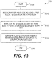
- Fig. 13 shows an example process 1300 implementing the third polar code puncturing technique according to an example of the disclosure.
- the process 1300 starts from S1301 and proceeds to S1310.
- a mother polar code is received.
- the received mother code can include a sequence of coded bits.
- the sequence of coded bits can have indices in an index set ⁇ 0, ..., N-1 ⁇ .
- the sequence of coded bits can include at least a first block having indices ⁇ 0, ..., i-1 ⁇ , a second block having indices ⁇ i, ..., i+k-1 ⁇ , a third block having indices ⁇ i+k, ..., i+k+k-1 ⁇ .
- the second and third block both have a length of k.
- the second and third blocks are interleaved with each other to form a rearranged sequence of coded bits.
- the rearranged sequence can be stored in a buffer.
- the last M coded bits are extracted from the rearranged sequence of coded bits to generate a punctured code having a length of M.
- the last M coded bits can read from the buffer.
- the process 1300 proceeds to S1399 and terminates at S1399.
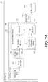
- Fig. 14 shows an apparatus 1400 for polar code matching according to an embodiment of the disclosure.
- the apparatus 1400 implements the third polar code puncturing technique.
- the apparatus 1400 includes a channel encoder 1440 and a modulator 1430.
- the channel encoder 1440 includes a polar encoder 1410 and a rate matching module 1420. Those components are coupled together as shown in Fig. 14 .
- the apparatus 1400 has structures and functionality similar to the apparatus 200 in Fig. 2 .
- the components 1440, 1410, and 1430 in Fig. 14 are similar to the counterparts 240, 210, and 230 in Fig. 2 in terms of structures and functions.
- the rate matching module 1420 is different from the rate matching module 220.
- the rate matching module 1420 can include a bit-reversal module 1422, an inter-leaver 1423, a rearranged output bits buffer 1425 and a bit selector 1424.
- the rate matching module 1420 is configured to receive a mother code 1402 of length N and accordingly generate a punctured code 1430 of length M.
- the bit-reversal module 1422 is configured to perform a bit-reversal permutation on the received mother code 1402 to generate a reordered mother code when the received mother code 1402 is generated based on a polar graph of the second type.
- the inter-leaver 1423 is configured to interleave two blocks of coded bits in the mother code 1402 or the reordered mother code to generate a sequence of rearranged output bits.
- the rearranged output bits buffer 1425 is configured to store the rearranged output bits corresponding.
- the bit selector 1424 is configured to exclude un-punctured output bits from the rearranged output bits buffer 1425 to generate the punctured code 1403.
- the polar encoder 1410 performs polar encoding.
- the bit-reversed module 1422 can receive the mother code 1402 of the first type, and perform a bit-reversal permutation operation to reorder the mother code 1402.
- the inter-leaver 1423 can perform an interleaving operation.
- the original mother code 1402 or the reordered mother code can include a sequence of output bits.
- the sequence of output bits can include at least a first, second and third successive blocks.
- the first block can include the first A number of output bits in the sequence.
- the second and third blocks can have a same length and each include B number of output bits in the sequence.
- the rate matching module 1420 can interleave the second and third blocks.
- a rearranged sequence can be created and stored into the rearranged output bits buffer 1425.
- the bit selector 1424 can subsequently read the last M number of output bits from the rearranged output bits buffer 1425 and output the M number of output bits as the punctured code 1403.
- the channel encoder 240 and 1440 in Figs. 2 or 14 can be implemented with hardware, software, or combination thereof.
- the channel encoder 240 or 1440 can be implemented with one or more integrated circuits (ICs), such as an application specific integrated circuit (ASIC), field programmable gate array (FPGA), and the like.
- the channel encoder 240 or 1440 can be implemented as software or firmware including instructions stored in a computer readable non-volatile storage media. The instructions, when executed by a processing circuit, causing the processing circuit to perform functions of the channel encoder 240 and 1440.
- the rate matching module 1420 in Fig. 14 example employs a puncturing scheme to realize rate matching functionality
- the rate matching module 1420 can employ more than one rate matching schemes to optimize its rate matching performance.
- the rate matching module 1420 can select one rate matching scheme from multiple rate matching schemes, such as puncturing, shortening, repetition, and the like. The selection can be based on some conditions, such as whether mother code rate, defined as a ratio of information bits length to a polar code length, is larger than a threshold, whether the mother code length is larger than a code length required by a transmission resource allocation, and the like.
- different rate matching schemes can be selected to achieve an optimal rate matching performance.
Landscapes
- Engineering & Computer Science (AREA)
- Computer Networks & Wireless Communication (AREA)
- Signal Processing (AREA)
- Physics & Mathematics (AREA)
- Probability & Statistics with Applications (AREA)
- Theoretical Computer Science (AREA)
- Error Detection And Correction (AREA)
- Detection And Prevention Of Errors In Transmission (AREA)
Claims (6)
- Procédé de perforation de code polaire, comprenant le fait :de recevoir (S1310) un code polaire mère comportant une séquence de bits codés (1202), la séquence de bits codés (1202) ayant des indices {0, ..., N-1} et comportant au moins un premier bloc de bits codés (B0) ayant des indices {0, ..., i-1}, un deuxième bloc de bits codés (B1) ayant des indices {i, ...,i+k-1}, un troisième bloc de bits codés (B2) ayant des indices {i+k, ..., i+k+k-1}, et un quatrième bloc de bits codés (B3) ayant des indices {i+k+k, ..., N-1} ;dans lequel le code polaire mère est généré sur la base d'une matrice génératrice GN ayant la forme de GN = F ⊗n n, où F ⊗n dénote un n-ième produit de Kronecher d'une matrice de base
 caractérisé par le fait :d'entrelacer (S1320) les bits codés du deuxième bloc de bits codés (B1) avec les bits codés du troisième bloc de bits codés (B2) pour former une séquence réarrangée de bits codés (1203) comportant les N bits codés et ayant les indices {..., i, i+k, ..., i+k-1, i+k+k-1, ...} ; etd'extraire (S1330) les M derniers bits codés (1234) ayant les indices {N-M, ..., N-1} à partir de la séquence réarrangée de bits codés (1203) pour générer un code perforé ayant une longueur de M.
 - Procédé de la revendication 1, dans lequel i=N/4, et i+k=N/2.
- Procédé de la revendication 1, comprenant en outre le fait :de stocker la séquence réarrangée de bits codés (1203) dans un tampon (1425),dans lequel l'extraction des M derniers bits codés (1234) de la séquence réarrangée de bits codés (1203) comporte la lecture des M derniers bits codés (1234) de la séquence réarrangée de bits codés (1203) à partir du tampon (1425).
- Appareil (1400) pour la perforation de code polaire, comprenant :
un circuit d'entrelacement (1423) configuré pour :recevoir un code polaire mère comportant une séquence de bits codés (1202), la séquence de bits codés (1202) ayant des indices {0, ..., N-1} et comportant au moins un premier bloc de bits codés (B0) ayant des indices {0, ..., i-1}, un deuxième bloc de bits codés (B1) ayant des indices {i, ..., i+k-1}, un troisième bloc de bits codés (B2) ayant des indices {i+k, ..., i+k+k-1}, et un quatrième bloc de bits codés (B3) ayant des indices {i+k+k, ..., N-1} ;dans lequel le code polaire mère est généré sur la base d'une matrice génératrice GN ayant la forme de GN = F ⊗n n, où F⊗n dénote un n-ième produit de Kronecher d'une matrice de base caractérisé en ce que le circuit d'entrelacement (1423) est en outre configuré pour :entrelacer les bits codés du deuxième bloc de bits codés (B1) avec les bits codés du troisième bloc de bits codés (B2) pour former une séquence réarrangée de bits codés (1203) comportant les N bits codés et ayant les indices {..., i, i+k, ..., i+k-1, i+k+k-1, ...} ;dans lequel l'appareil (1400) comprend en outreun circuit de sélecteur de bits (1424) configuré pour extraire les M derniers bits codés (1234) à partir de la séquence réarrangée de bits codés (1203) ayant des indices {N-M, ..., N-1} pour générer un code perforé d'une longueur de M.
 - Appareil (1400) de la revendication 4, dans lequel i=N/4, et i+k=N/2.
- Appareil (1400) de la revendication 4, comprenant en outre un tampon de bits codés réarrangés (1425) configuré pour stocker la séquence réarrangée de bits codés (1203), dans lequel le sélecteur de bits (1424) est configuré pour lire les M derniers bits codés (1234) à partir du tampon (1425).
Applications Claiming Priority (2)
| Application Number | Priority Date | Filing Date | Title |
|---|---|---|---|
| US201662335858P | 2016-05-13 | 2016-05-13 | |
| US201762455054P | 2017-02-06 | 2017-02-06 |
Publications (2)
| Publication Number | Publication Date |
|---|---|
| EP3247042A1 EP3247042A1 (fr) | 2017-11-22 |
| EP3247042B1 true EP3247042B1 (fr) | 2020-09-30 |
Family
ID=58709379
Family Applications (1)
| Application Number | Title | Priority Date | Filing Date |
|---|---|---|---|
| EP17171096.5A Active EP3247042B1 (fr) | 2016-05-13 | 2017-05-15 | Perforation de bits pour codes polaires |
Country Status (2)
| Country | Link |
|---|---|
| US (1) | US10171204B2 (fr) |
| EP (1) | EP3247042B1 (fr) |
Families Citing this family (33)
| Publication number | Priority date | Publication date | Assignee | Title |
|---|---|---|---|---|
| RU2679223C2 (ru) | 2013-11-11 | 2019-02-06 | Хуавэй Текнолоджиз Ко., Лтд. | Способ и устройство для полярного кодирования |
| US10291264B2 (en) * | 2016-06-17 | 2019-05-14 | Huawei Technologies Co., Ltd. | Systems and methods for rate matching when using general polar codes |
| US10579452B2 (en) | 2016-06-17 | 2020-03-03 | Huawei Technologies Co., Ltd. | Systems and methods for rate matching via a heterogeneous kernel when using general polar codes |
| CN107733554B (zh) * | 2016-08-11 | 2020-09-25 | 华为技术有限公司 | 极化码的速率匹配方法和装置 |
| JP6734577B2 (ja) * | 2016-10-21 | 2020-08-05 | 日本電気株式会社 | ポーラ符号のためのパンクチャリングパターンの設計 |
| WO2018106001A1 (fr) * | 2016-12-06 | 2018-06-14 | 엘지전자 주식회사 | Procédé et dispositif de transmission d'informations de commande à l'aide d'un code polaire |
| CN107342843B (zh) * | 2017-01-05 | 2023-10-20 | 华为技术有限公司 | 速率匹配方法、编码装置和通信装置 |
| WO2018126476A1 (fr) * | 2017-01-09 | 2018-07-12 | Qualcomm Incorporated | Schéma d'adaptation de débit pour canaux de commande utilisant des codes polaires |
| US10313056B2 (en) * | 2017-02-06 | 2019-06-04 | Mitsubishi Electric Research Laboratories, Inc. | Irregular polar code encoding |
| AU2018239415B2 (en) * | 2017-03-22 | 2023-02-23 | Interdigital Patent Holdings, Inc. | Sub-block wise interleaving for polar coding systems, procedures, and signaling |
| CN108683479B (zh) | 2017-03-25 | 2019-08-13 | 华为技术有限公司 | 一种速率匹配的方法和装置 |
| CN108809334B (zh) * | 2017-05-05 | 2021-07-20 | 中兴通讯股份有限公司 | 序列确定方法及装置、设备 |
| EP3622646B1 (fr) * | 2017-05-08 | 2020-10-21 | Coherent Logix, Inc. | Pondération de polarisation améliorée de manière à permettre une évolutivité dans une distribution de bits de codes polaires |
| GB2563418B (en) * | 2017-06-15 | 2020-04-22 | Accelercomm Ltd | Polar encoder, communication unit, integrated circuit and method therefor |
| CN109150198B (zh) * | 2017-06-16 | 2021-05-14 | 华为技术有限公司 | 一种极化码的交织处理方法及装置 |
| KR102378324B1 (ko) * | 2017-06-19 | 2022-03-25 | 삼성전자 주식회사 | 통신 및 방송 시스템을 위한 부호율-조정 방법 및 장치 |
| US10833705B2 (en) * | 2017-08-02 | 2020-11-10 | Qualcomm Incorporated | Information bit distribution design for polar codes |
| US10873347B2 (en) * | 2017-08-07 | 2020-12-22 | Mediatek Inc. | Channel bit interleaver design for polar coding chain |
| CN109391358B (zh) * | 2017-08-11 | 2021-09-21 | 华为技术有限公司 | 极化码编码的方法和装置 |
| CN111034074B (zh) * | 2017-08-11 | 2021-11-30 | 中兴通讯股份有限公司 | 用于处理极化码的系统和方法 |
| CN108055107B (zh) * | 2017-12-12 | 2020-06-02 | 安徽大学 | 一种基于穿刺极化码的信息通信方法 |
| CN109962753B (zh) * | 2017-12-26 | 2022-02-18 | 华为技术有限公司 | 一种速率匹配和极化码编码的方法和设备 |
| CN108199804B (zh) * | 2017-12-31 | 2020-12-04 | 华北电力大学(保定) | 一种同时具有纠错与加密功能的串口数据发送方法 |
| CN110048802B (zh) * | 2018-01-16 | 2021-12-28 | 华为技术有限公司 | 数据传输方法及装置、系统 |
| WO2019164416A1 (fr) * | 2018-02-22 | 2019-08-29 | Huawei Technologies Co., Ltd. | Dispositifs et procédés de génération de codes polaires de bloc perforés |
| US10666392B2 (en) * | 2018-03-29 | 2020-05-26 | Huawei Technologies Co., Ltd. | Apparatus and methods for rate matching in polar coding |
| TW202037103A (zh) * | 2018-08-14 | 2020-10-01 | 財團法人工業技術研究院 | 有部分資訊下進行極性碼傳輸的方法和使用該方法的裝置 |
| KR20210006807A (ko) * | 2019-07-09 | 2021-01-19 | 삼성전자주식회사 | 통신 시스템에서 신호 송수신 장치 및 방법 |
| TWI765204B (zh) * | 2019-12-31 | 2022-05-21 | 國立中正大學 | 交錯極化碼產生方法與其使用的交錯極化碼編碼器 |
| CN115004559B (zh) * | 2020-01-20 | 2026-01-02 | 上海诺基亚贝尔股份有限公司 | 基于数据隐私保护的极性编码 |
| CN113315600B (zh) * | 2020-02-26 | 2022-07-22 | 北京大学 | 一种系统极化码均匀凿孔方法 |
| JP7183479B2 (ja) * | 2020-04-28 | 2022-12-05 | 三菱電機株式会社 | 符号化回路、復号回路、制御回路、記憶媒体および復号方法 |
| WO2024192762A1 (fr) * | 2023-03-23 | 2024-09-26 | Huawei Technologies Co., Ltd. | Procédés, systèmes et appareil de placement de valeur de bit dans un codage polaire |
Family Cites Families (10)
| Publication number | Priority date | Publication date | Assignee | Title |
|---|---|---|---|---|
| US8184726B2 (en) * | 2007-09-10 | 2012-05-22 | Industrial Technology Research Institute | Method and apparatus for multi-rate control in a multi-channel communication system |
| CN102122966B (zh) | 2011-04-15 | 2012-11-14 | 北京邮电大学 | 基于信道极化的交错结构重复码的编码器及其编译码方法 |
| KR102015121B1 (ko) | 2012-10-17 | 2019-08-28 | 삼성전자주식회사 | 불휘발성 메모리 장치를 제어하도록 구성되는 컨트롤러 및 컨트롤러의 동작 방법 |
| EP2945291B1 (fr) * | 2013-01-11 | 2019-12-18 | Sun Patent Trust | Procédé de traitement de données, procédé de précodage et dispositif de communication |
| US9362956B2 (en) | 2013-01-23 | 2016-06-07 | Samsung Electronics Co., Ltd. | Method and system for encoding and decoding data using concatenated polar codes |
| US9007241B2 (en) | 2013-09-16 | 2015-04-14 | Seagate Technology Llc | Reduced polar codes |
| EP3073660B1 (fr) | 2013-11-20 | 2020-06-24 | Huawei Technologies Co., Ltd. | Procédé et dispositif de traitement de code polaire |
| KR102157667B1 (ko) * | 2014-05-15 | 2020-09-18 | 삼성전자주식회사 | 천공 장치 및 그의 천공 방법 |
| US9742440B2 (en) * | 2015-03-25 | 2017-08-22 | Samsung Electronics Co., Ltd | HARQ rate-compatible polar codes for wireless channels |
| US10231121B2 (en) | 2015-06-24 | 2019-03-12 | Lg Electronics Inc. | Security communication using polar code scheme |
-
2017
- 2017-05-15 EP EP17171096.5A patent/EP3247042B1/fr active Active
- 2017-05-15 US US15/595,189 patent/US10171204B2/en active Active
Non-Patent Citations (1)
| Title |
|---|
| None * |
Also Published As
| Publication number | Publication date |
|---|---|
| EP3247042A1 (fr) | 2017-11-22 |
| US10171204B2 (en) | 2019-01-01 |
| US20170331590A1 (en) | 2017-11-16 |
Similar Documents
| Publication | Publication Date | Title |
|---|---|---|
| EP3247042B1 (fr) | Perforation de bits pour codes polaires | |
| US10432234B2 (en) | Low complexity rate matching for polar codes | |
| KR102541319B1 (ko) | 무선 통신 시스템에서 극 부호를 이용한 부호화 및 복호화를 위한 장치 및 방법 | |
| US20240031058A1 (en) | Encoding and modulation method, demodulation and decoding method, and apparatus | |
| JP5648224B2 (ja) | 低密度パリティ検査符号を使用するシステムにおけるチャネル符号化及び復号化方法並びにその装置 | |
| RU2426259C1 (ru) | Способ для передачи управляющей информации и способ для формирования кодового слова управляющей информации | |
| CN106027068B (zh) | 用于无线信道的harq速率兼容的极性码 | |
| US11171741B2 (en) | Polar code transmission method and apparatus | |
| JP6871396B2 (ja) | 情報を処理するための方法および装置、通信デバイス、ならびに通信システム | |
| US7190737B2 (en) | Multi-mode block-coded modulation/demodulation method | |
| JP6915061B2 (ja) | 情報処理方法、装置、通信デバイスおよび通信システム | |
| US10440659B2 (en) | Method and device for encoding in wireless communication system | |
| US10356788B2 (en) | System and method for high-rate sparse code multiple access in downlink | |
| US11451324B2 (en) | Bit selection for hybrid automatic repeat requests | |
| US7904792B2 (en) | Apparatus and method for transmitting/receiving signal in a communication system | |
| CA3057817A1 (fr) | Procede pour effectuer un codage sur la base d'une matrice de controle de parite de code de controle de parite a faible densite (ldpc) dans un systeme de communication sans fil et terminal l'utilisant | |
| US10454535B2 (en) | Apparatus and method for receiving signal in wireless communication system | |
| EP1662687B1 (fr) | Méthode et appareil pour l'entrelacement de canal dans un système de communication mobile | |
| US9203443B2 (en) | Optimal period rate matching for turbo coding | |
| KR20190021652A (ko) | 무선 통신 시스템에서 극 부호를 결정하기 위한 장치 및 방법 | |
| TWI653840B (zh) | 極化碼打孔方法及裝置 | |
| US7954035B2 (en) | Low density parity check encoder using costas array, and channel encoder of high speed portable internet system comprising the same and channel encoding method | |
| WO2024192945A1 (fr) | Procédés, systèmes, et appareil pour codage polaire sans débit et redondance incrémentale | |
| KR20060063003A (ko) | 반복에 의한 부호어 생성 방법 | |
| KR20080084401A (ko) | 블록 저밀도 패리티 검사 부호를 사용하는 통신 시스템에서신호 송수신 장치 및 방법 |
Legal Events
| Date | Code | Title | Description |
|---|---|---|---|
| PUAI | Public reference made under article 153(3) epc to a published international application that has entered the european phase |
Free format text: ORIGINAL CODE: 0009012 |
|
| STAA | Information on the status of an ep patent application or granted ep patent |
Free format text: STATUS: THE APPLICATION HAS BEEN PUBLISHED |
|
| AK | Designated contracting states |
Kind code of ref document: A1 Designated state(s): AL AT BE BG CH CY CZ DE DK EE ES FI FR GB GR HR HU IE IS IT LI LT LU LV MC MK MT NL NO PL PT RO RS SE SI SK SM TR |
|
| AX | Request for extension of the european patent |
Extension state: BA ME |
|
| STAA | Information on the status of an ep patent application or granted ep patent |
Free format text: STATUS: REQUEST FOR EXAMINATION WAS MADE |
|
| 17P | Request for examination filed |
Effective date: 20180522 |
|
| RBV | Designated contracting states (corrected) |
Designated state(s): AL AT BE BG CH CY CZ DE DK EE ES FI FR GB GR HR HU IE IS IT LI LT LU LV MC MK MT NL NO PL PT RO RS SE SI SK SM TR |
|
| GRAP | Despatch of communication of intention to grant a patent |
Free format text: ORIGINAL CODE: EPIDOSNIGR1 |
|
| STAA | Information on the status of an ep patent application or granted ep patent |
Free format text: STATUS: GRANT OF PATENT IS INTENDED |
|
| INTG | Intention to grant announced |
Effective date: 20200416 |
|
| GRAS | Grant fee paid |
Free format text: ORIGINAL CODE: EPIDOSNIGR3 |
|
| GRAA | (expected) grant |
Free format text: ORIGINAL CODE: 0009210 |
|
| STAA | Information on the status of an ep patent application or granted ep patent |
Free format text: STATUS: THE PATENT HAS BEEN GRANTED |
|
| AK | Designated contracting states |
Kind code of ref document: B1 Designated state(s): AL AT BE BG CH CY CZ DE DK EE ES FI FR GB GR HR HU IE IS IT LI LT LU LV MC MK MT NL NO PL PT RO RS SE SI SK SM TR |
|
| RAP1 | Party data changed (applicant data changed or rights of an application transferred) |
Owner name: MEDIATEK INC. |
|
| REG | Reference to a national code |
Ref country code: CH Ref legal event code: EP Ref country code: GB Ref legal event code: FG4D |
|
| RIN1 | Information on inventor provided before grant (corrected) |
Inventor name: CHIU, MAO-CHING Inventor name: WU, WEI-DE |
|
| REG | Reference to a national code |
Ref country code: AT Ref legal event code: REF Ref document number: 1319868 Country of ref document: AT Kind code of ref document: T Effective date: 20201015 |
|
| REG | Reference to a national code |
Ref country code: DE Ref legal event code: R096 Ref document number: 602017024443 Country of ref document: DE |
|
| REG | Reference to a national code |
Ref country code: IE Ref legal event code: FG4D |
|
| PG25 | Lapsed in a contracting state [announced via postgrant information from national office to epo] |
Ref country code: HR Free format text: LAPSE BECAUSE OF FAILURE TO SUBMIT A TRANSLATION OF THE DESCRIPTION OR TO PAY THE FEE WITHIN THE PRESCRIBED TIME-LIMIT Effective date: 20200930 Ref country code: SE Free format text: LAPSE BECAUSE OF FAILURE TO SUBMIT A TRANSLATION OF THE DESCRIPTION OR TO PAY THE FEE WITHIN THE PRESCRIBED TIME-LIMIT Effective date: 20200930 Ref country code: BG Free format text: LAPSE BECAUSE OF FAILURE TO SUBMIT A TRANSLATION OF THE DESCRIPTION OR TO PAY THE FEE WITHIN THE PRESCRIBED TIME-LIMIT Effective date: 20201230 Ref country code: GR Free format text: LAPSE BECAUSE OF FAILURE TO SUBMIT A TRANSLATION OF THE DESCRIPTION OR TO PAY THE FEE WITHIN THE PRESCRIBED TIME-LIMIT Effective date: 20201231 Ref country code: FI Free format text: LAPSE BECAUSE OF FAILURE TO SUBMIT A TRANSLATION OF THE DESCRIPTION OR TO PAY THE FEE WITHIN THE PRESCRIBED TIME-LIMIT Effective date: 20200930 Ref country code: NO Free format text: LAPSE BECAUSE OF FAILURE TO SUBMIT A TRANSLATION OF THE DESCRIPTION OR TO PAY THE FEE WITHIN THE PRESCRIBED TIME-LIMIT Effective date: 20201230 |
|
| REG | Reference to a national code |
Ref country code: AT Ref legal event code: MK05 Ref document number: 1319868 Country of ref document: AT Kind code of ref document: T Effective date: 20200930 |
|
| PG25 | Lapsed in a contracting state [announced via postgrant information from national office to epo] |
Ref country code: RS Free format text: LAPSE BECAUSE OF FAILURE TO SUBMIT A TRANSLATION OF THE DESCRIPTION OR TO PAY THE FEE WITHIN THE PRESCRIBED TIME-LIMIT Effective date: 20200930 Ref country code: LV Free format text: LAPSE BECAUSE OF FAILURE TO SUBMIT A TRANSLATION OF THE DESCRIPTION OR TO PAY THE FEE WITHIN THE PRESCRIBED TIME-LIMIT Effective date: 20200930 |
|
| REG | Reference to a national code |
Ref country code: NL Ref legal event code: MP Effective date: 20200930 |
|
| REG | Reference to a national code |
Ref country code: LT Ref legal event code: MG4D |
|
| PG25 | Lapsed in a contracting state [announced via postgrant information from national office to epo] |
Ref country code: SM Free format text: LAPSE BECAUSE OF FAILURE TO SUBMIT A TRANSLATION OF THE DESCRIPTION OR TO PAY THE FEE WITHIN THE PRESCRIBED TIME-LIMIT Effective date: 20200930 Ref country code: EE Free format text: LAPSE BECAUSE OF FAILURE TO SUBMIT A TRANSLATION OF THE DESCRIPTION OR TO PAY THE FEE WITHIN THE PRESCRIBED TIME-LIMIT Effective date: 20200930 Ref country code: RO Free format text: LAPSE BECAUSE OF FAILURE TO SUBMIT A TRANSLATION OF THE DESCRIPTION OR TO PAY THE FEE WITHIN THE PRESCRIBED TIME-LIMIT Effective date: 20200930 Ref country code: PT Free format text: LAPSE BECAUSE OF FAILURE TO SUBMIT A TRANSLATION OF THE DESCRIPTION OR TO PAY THE FEE WITHIN THE PRESCRIBED TIME-LIMIT Effective date: 20210201 Ref country code: CZ Free format text: LAPSE BECAUSE OF FAILURE TO SUBMIT A TRANSLATION OF THE DESCRIPTION OR TO PAY THE FEE WITHIN THE PRESCRIBED TIME-LIMIT Effective date: 20200930 Ref country code: LT Free format text: LAPSE BECAUSE OF FAILURE TO SUBMIT A TRANSLATION OF THE DESCRIPTION OR TO PAY THE FEE WITHIN THE PRESCRIBED TIME-LIMIT Effective date: 20200930 Ref country code: NL Free format text: LAPSE BECAUSE OF FAILURE TO SUBMIT A TRANSLATION OF THE DESCRIPTION OR TO PAY THE FEE WITHIN THE PRESCRIBED TIME-LIMIT Effective date: 20200930 |
|
| PG25 | Lapsed in a contracting state [announced via postgrant information from national office to epo] |
Ref country code: ES Free format text: LAPSE BECAUSE OF FAILURE TO SUBMIT A TRANSLATION OF THE DESCRIPTION OR TO PAY THE FEE WITHIN THE PRESCRIBED TIME-LIMIT Effective date: 20200930 Ref country code: AT Free format text: LAPSE BECAUSE OF FAILURE TO SUBMIT A TRANSLATION OF THE DESCRIPTION OR TO PAY THE FEE WITHIN THE PRESCRIBED TIME-LIMIT Effective date: 20200930 Ref country code: AL Free format text: LAPSE BECAUSE OF FAILURE TO SUBMIT A TRANSLATION OF THE DESCRIPTION OR TO PAY THE FEE WITHIN THE PRESCRIBED TIME-LIMIT Effective date: 20200930 Ref country code: IS Free format text: LAPSE BECAUSE OF FAILURE TO SUBMIT A TRANSLATION OF THE DESCRIPTION OR TO PAY THE FEE WITHIN THE PRESCRIBED TIME-LIMIT Effective date: 20210130 Ref country code: PL Free format text: LAPSE BECAUSE OF FAILURE TO SUBMIT A TRANSLATION OF THE DESCRIPTION OR TO PAY THE FEE WITHIN THE PRESCRIBED TIME-LIMIT Effective date: 20200930 |
|
| PG25 | Lapsed in a contracting state [announced via postgrant information from national office to epo] |
Ref country code: SK Free format text: LAPSE BECAUSE OF FAILURE TO SUBMIT A TRANSLATION OF THE DESCRIPTION OR TO PAY THE FEE WITHIN THE PRESCRIBED TIME-LIMIT Effective date: 20200930 |
|
| REG | Reference to a national code |
Ref country code: DE Ref legal event code: R097 Ref document number: 602017024443 Country of ref document: DE |
|
| PLBE | No opposition filed within time limit |
Free format text: ORIGINAL CODE: 0009261 |
|
| STAA | Information on the status of an ep patent application or granted ep patent |
Free format text: STATUS: NO OPPOSITION FILED WITHIN TIME LIMIT |
|
| PG25 | Lapsed in a contracting state [announced via postgrant information from national office to epo] |
Ref country code: DK Free format text: LAPSE BECAUSE OF FAILURE TO SUBMIT A TRANSLATION OF THE DESCRIPTION OR TO PAY THE FEE WITHIN THE PRESCRIBED TIME-LIMIT Effective date: 20200930 |
|
| 26N | No opposition filed |
Effective date: 20210701 |
|
| PG25 | Lapsed in a contracting state [announced via postgrant information from national office to epo] |
Ref country code: IT Free format text: LAPSE BECAUSE OF FAILURE TO SUBMIT A TRANSLATION OF THE DESCRIPTION OR TO PAY THE FEE WITHIN THE PRESCRIBED TIME-LIMIT Effective date: 20200930 |
|
| PG25 | Lapsed in a contracting state [announced via postgrant information from national office to epo] |
Ref country code: SI Free format text: LAPSE BECAUSE OF FAILURE TO SUBMIT A TRANSLATION OF THE DESCRIPTION OR TO PAY THE FEE WITHIN THE PRESCRIBED TIME-LIMIT Effective date: 20200930 |
|
| REG | Reference to a national code |
Ref country code: CH Ref legal event code: PL |
|
| PG25 | Lapsed in a contracting state [announced via postgrant information from national office to epo] |
Ref country code: MC Free format text: LAPSE BECAUSE OF FAILURE TO SUBMIT A TRANSLATION OF THE DESCRIPTION OR TO PAY THE FEE WITHIN THE PRESCRIBED TIME-LIMIT Effective date: 20200930 Ref country code: LU Free format text: LAPSE BECAUSE OF NON-PAYMENT OF DUE FEES Effective date: 20210515 Ref country code: LI Free format text: LAPSE BECAUSE OF NON-PAYMENT OF DUE FEES Effective date: 20210531 Ref country code: CH Free format text: LAPSE BECAUSE OF NON-PAYMENT OF DUE FEES Effective date: 20210531 |
|
| REG | Reference to a national code |
Ref country code: BE Ref legal event code: MM Effective date: 20210531 |
|
| PG25 | Lapsed in a contracting state [announced via postgrant information from national office to epo] |
Ref country code: IE Free format text: LAPSE BECAUSE OF NON-PAYMENT OF DUE FEES Effective date: 20210515 |
|
| PG25 | Lapsed in a contracting state [announced via postgrant information from national office to epo] |
Ref country code: IS Free format text: LAPSE BECAUSE OF FAILURE TO SUBMIT A TRANSLATION OF THE DESCRIPTION OR TO PAY THE FEE WITHIN THE PRESCRIBED TIME-LIMIT Effective date: 20210130 |
|
| PG25 | Lapsed in a contracting state [announced via postgrant information from national office to epo] |
Ref country code: BE Free format text: LAPSE BECAUSE OF NON-PAYMENT OF DUE FEES Effective date: 20210531 |
|
| PG25 | Lapsed in a contracting state [announced via postgrant information from national office to epo] |
Ref country code: HU Free format text: LAPSE BECAUSE OF FAILURE TO SUBMIT A TRANSLATION OF THE DESCRIPTION OR TO PAY THE FEE WITHIN THE PRESCRIBED TIME-LIMIT; INVALID AB INITIO Effective date: 20170515 |
|
| PG25 | Lapsed in a contracting state [announced via postgrant information from national office to epo] |
Ref country code: CY Free format text: LAPSE BECAUSE OF FAILURE TO SUBMIT A TRANSLATION OF THE DESCRIPTION OR TO PAY THE FEE WITHIN THE PRESCRIBED TIME-LIMIT Effective date: 20200930 |
|
| P01 | Opt-out of the competence of the unified patent court (upc) registered |
Effective date: 20230607 |
|
| PG25 | Lapsed in a contracting state [announced via postgrant information from national office to epo] |
Ref country code: MK Free format text: LAPSE BECAUSE OF FAILURE TO SUBMIT A TRANSLATION OF THE DESCRIPTION OR TO PAY THE FEE WITHIN THE PRESCRIBED TIME-LIMIT Effective date: 20200930 |
|
| PG25 | Lapsed in a contracting state [announced via postgrant information from national office to epo] |
Ref country code: TR Free format text: LAPSE BECAUSE OF FAILURE TO SUBMIT A TRANSLATION OF THE DESCRIPTION OR TO PAY THE FEE WITHIN THE PRESCRIBED TIME-LIMIT Effective date: 20200930 |
|
| PG25 | Lapsed in a contracting state [announced via postgrant information from national office to epo] |
Ref country code: MT Free format text: LAPSE BECAUSE OF FAILURE TO SUBMIT A TRANSLATION OF THE DESCRIPTION OR TO PAY THE FEE WITHIN THE PRESCRIBED TIME-LIMIT Effective date: 20200930 |
|
| PGFP | Annual fee paid to national office [announced via postgrant information from national office to epo] |
Ref country code: DE Payment date: 20250325 Year of fee payment: 9 |
|
| REG | Reference to a national code |
Ref country code: DE Ref legal event code: R081 Ref document number: 602017024443 Country of ref document: DE Owner name: HFI INNOVATION INC., ZHUBEI CITY, TW Free format text: FORMER OWNER: MEDIATEK INC., HSIN-CHU, TW |
|
| PGFP | Annual fee paid to national office [announced via postgrant information from national office to epo] |
Ref country code: GB Payment date: 20260313 Year of fee payment: 10 |
|
| PGFP | Annual fee paid to national office [announced via postgrant information from national office to epo] |
Ref country code: FR Payment date: 20260309 Year of fee payment: 10 |
|
| REG | Reference to a national code |
Ref country code: GB Ref legal event code: 732E Free format text: REGISTERED BETWEEN 20260326 AND 20260401 |