EP3247111A1 - Rundfunksignalsendevorrichtung, rundfunksignalempfangsvorrichtung, rundfunksignalsendeverfahren und rundfunksignalempfangsverfahren - Google Patents
Rundfunksignalsendevorrichtung, rundfunksignalempfangsvorrichtung, rundfunksignalsendeverfahren und rundfunksignalempfangsverfahren Download PDFInfo
- Publication number
- EP3247111A1 EP3247111A1 EP16737523.7A EP16737523A EP3247111A1 EP 3247111 A1 EP3247111 A1 EP 3247111A1 EP 16737523 A EP16737523 A EP 16737523A EP 3247111 A1 EP3247111 A1 EP 3247111A1
- Authority
- EP
- European Patent Office
- Prior art keywords
- service
- signaling
- information
- present
- packet
- Prior art date
- Legal status (The legal status is an assumption and is not a legal conclusion. Google has not performed a legal analysis and makes no representation as to the accuracy of the status listed.)
- Withdrawn
Links
Images


Classifications
-
- H—ELECTRICITY
- H04—ELECTRIC COMMUNICATION TECHNIQUE
- H04H—BROADCAST COMMUNICATION
- H04H20/00—Arrangements for broadcast or for distribution combined with broadcast
- H04H20/18—Arrangements for synchronising broadcast or distribution via plural systems
-
- H—ELECTRICITY
- H04—ELECTRIC COMMUNICATION TECHNIQUE
- H04N—PICTORIAL COMMUNICATION, e.g. TELEVISION
- H04N21/00—Selective content distribution, e.g. interactive television or video on demand [VOD]
- H04N21/40—Client devices specifically adapted for the reception of or interaction with content, e.g. set-top-box [STB]; Operations thereof
- H04N21/47—End-user applications
- H04N21/488—Data services, e.g. news ticker
- H04N21/4882—Data services, e.g. news ticker for displaying messages, e.g. warnings, reminders
-
- H—ELECTRICITY
- H04—ELECTRIC COMMUNICATION TECHNIQUE
- H04H—BROADCAST COMMUNICATION
- H04H20/00—Arrangements for broadcast or for distribution combined with broadcast
- H04H20/42—Arrangements for resource management
-
- H—ELECTRICITY
- H04—ELECTRIC COMMUNICATION TECHNIQUE
- H04H—BROADCAST COMMUNICATION
- H04H20/00—Arrangements for broadcast or for distribution combined with broadcast
- H04H20/86—Arrangements characterised by the broadcast information itself
- H04H20/93—Arrangements characterised by the broadcast information itself which locates resources of other pieces of information, e.g. URL [Uniform Resource Locator]
-
- H—ELECTRICITY
- H04—ELECTRIC COMMUNICATION TECHNIQUE
- H04H—BROADCAST COMMUNICATION
- H04H60/00—Arrangements for broadcast applications with a direct linking to broadcast information or broadcast space-time; Broadcast-related systems
- H04H60/68—Systems specially adapted for using specific information, e.g. geographical or meteorological information
- H04H60/72—Systems specially adapted for using specific information, e.g. geographical or meteorological information using electronic programme guides [EPG]
-
- H—ELECTRICITY
- H04—ELECTRIC COMMUNICATION TECHNIQUE
- H04H—BROADCAST COMMUNICATION
- H04H60/00—Arrangements for broadcast applications with a direct linking to broadcast information or broadcast space-time; Broadcast-related systems
- H04H60/76—Arrangements characterised by transmission systems other than for broadcast, e.g. the Internet
- H04H60/78—Arrangements characterised by transmission systems other than for broadcast, e.g. the Internet characterised by source locations or destination locations
- H04H60/80—Arrangements characterised by transmission systems other than for broadcast, e.g. the Internet characterised by source locations or destination locations characterised by transmission among terminal devices
-
- H—ELECTRICITY
- H04—ELECTRIC COMMUNICATION TECHNIQUE
- H04H—BROADCAST COMMUNICATION
- H04H60/00—Arrangements for broadcast applications with a direct linking to broadcast information or broadcast space-time; Broadcast-related systems
- H04H60/76—Arrangements characterised by transmission systems other than for broadcast, e.g. the Internet
- H04H60/81—Arrangements characterised by transmission systems other than for broadcast, e.g. the Internet characterised by the transmission system itself
- H04H60/82—Arrangements characterised by transmission systems other than for broadcast, e.g. the Internet characterised by the transmission system itself the transmission system being the Internet
-
- H—ELECTRICITY
- H04—ELECTRIC COMMUNICATION TECHNIQUE
- H04L—TRANSMISSION OF DIGITAL INFORMATION, e.g. TELEGRAPHIC COMMUNICATION
- H04L65/00—Network arrangements, protocols or services for supporting real-time applications in data packet communication
- H04L65/60—Network streaming of media packets
- H04L65/65—Network streaming protocols, e.g. real-time transport protocol [RTP] or real-time control protocol [RTCP]
-
- H—ELECTRICITY
- H04—ELECTRIC COMMUNICATION TECHNIQUE
- H04L—TRANSMISSION OF DIGITAL INFORMATION, e.g. TELEGRAPHIC COMMUNICATION
- H04L65/00—Network arrangements, protocols or services for supporting real-time applications in data packet communication
- H04L65/60—Network streaming of media packets
- H04L65/75—Media network packet handling
-
- H—ELECTRICITY
- H04—ELECTRIC COMMUNICATION TECHNIQUE
- H04L—TRANSMISSION OF DIGITAL INFORMATION, e.g. TELEGRAPHIC COMMUNICATION
- H04L65/00—Network arrangements, protocols or services for supporting real-time applications in data packet communication
- H04L65/80—Responding to QoS
-
- H—ELECTRICITY
- H04—ELECTRIC COMMUNICATION TECHNIQUE
- H04L—TRANSMISSION OF DIGITAL INFORMATION, e.g. TELEGRAPHIC COMMUNICATION
- H04L67/00—Network arrangements or protocols for supporting network services or applications
- H04L67/01—Protocols
- H04L67/02—Protocols based on web technology, e.g. hypertext transfer protocol [HTTP]
-
- H—ELECTRICITY
- H04—ELECTRIC COMMUNICATION TECHNIQUE
- H04N—PICTORIAL COMMUNICATION, e.g. TELEVISION
- H04N21/00—Selective content distribution, e.g. interactive television or video on demand [VOD]
- H04N21/20—Servers specifically adapted for the distribution of content, e.g. VOD servers; Operations thereof
- H04N21/23—Processing of content or additional data; Elementary server operations; Server middleware
- H04N21/234—Processing of video elementary streams, e.g. splicing of video streams or manipulating encoded video stream scene graphs
- H04N21/2343—Processing of video elementary streams, e.g. splicing of video streams or manipulating encoded video stream scene graphs involving reformatting operations of video signals for distribution or compliance with end-user requests or end-user device requirements
-
- H—ELECTRICITY
- H04—ELECTRIC COMMUNICATION TECHNIQUE
- H04N—PICTORIAL COMMUNICATION, e.g. TELEVISION
- H04N21/00—Selective content distribution, e.g. interactive television or video on demand [VOD]
- H04N21/20—Servers specifically adapted for the distribution of content, e.g. VOD servers; Operations thereof
- H04N21/23—Processing of content or additional data; Elementary server operations; Server middleware
- H04N21/236—Assembling of a multiplex stream, e.g. transport stream, by combining a video stream with other content or additional data, e.g. inserting a URL [Uniform Resource Locator] into a video stream, multiplexing software data into a video stream; Remultiplexing of multiplex streams; Insertion of stuffing bits into the multiplex stream, e.g. to obtain a constant bit-rate; Assembling of a packetised elementary stream
-
- H—ELECTRICITY
- H04—ELECTRIC COMMUNICATION TECHNIQUE
- H04N—PICTORIAL COMMUNICATION, e.g. TELEVISION
- H04N21/00—Selective content distribution, e.g. interactive television or video on demand [VOD]
- H04N21/40—Client devices specifically adapted for the reception of or interaction with content, e.g. set-top-box [STB]; Operations thereof
- H04N21/41—Structure of client; Structure of client peripherals
- H04N21/4104—Peripherals receiving signals from specially adapted client devices
- H04N21/4122—Peripherals receiving signals from specially adapted client devices additional display device, e.g. video projector
-
- H—ELECTRICITY
- H04—ELECTRIC COMMUNICATION TECHNIQUE
- H04N—PICTORIAL COMMUNICATION, e.g. TELEVISION
- H04N21/00—Selective content distribution, e.g. interactive television or video on demand [VOD]
- H04N21/40—Client devices specifically adapted for the reception of or interaction with content, e.g. set-top-box [STB]; Operations thereof
- H04N21/43—Processing of content or additional data, e.g. demultiplexing additional data from a digital video stream; Elementary client operations, e.g. monitoring of home network or synchronising decoder's clock; Client middleware
- H04N21/436—Interfacing a local distribution network, e.g. communicating with another STB or one or more peripheral devices inside the home
- H04N21/43615—Interfacing a Home Network, e.g. for connecting the client to a plurality of peripherals
-
- H—ELECTRICITY
- H04—ELECTRIC COMMUNICATION TECHNIQUE
- H04N—PICTORIAL COMMUNICATION, e.g. TELEVISION
- H04N21/00—Selective content distribution, e.g. interactive television or video on demand [VOD]
- H04N21/60—Network structure or processes for video distribution between server and client or between remote clients; Control signalling between clients, server and network components; Transmission of management data between server and client, e.g. sending from server to client commands for recording incoming content stream; Communication details between server and client
- H04N21/63—Control signaling related to video distribution between client, server and network components; Network processes for video distribution between server and clients or between remote clients, e.g. transmitting basic layer and enhancement layers over different transmission paths, setting up a peer-to-peer communication via Internet between remote STB's; Communication protocols; Addressing
- H04N21/643—Communication protocols
- H04N21/64322—IP
-
- H—ELECTRICITY
- H04—ELECTRIC COMMUNICATION TECHNIQUE
- H04N—PICTORIAL COMMUNICATION, e.g. TELEVISION
- H04N21/00—Selective content distribution, e.g. interactive television or video on demand [VOD]
- H04N21/60—Network structure or processes for video distribution between server and client or between remote clients; Control signalling between clients, server and network components; Transmission of management data between server and client, e.g. sending from server to client commands for recording incoming content stream; Communication details between server and client
- H04N21/63—Control signaling related to video distribution between client, server and network components; Network processes for video distribution between server and clients or between remote clients, e.g. transmitting basic layer and enhancement layers over different transmission paths, setting up a peer-to-peer communication via Internet between remote STB's; Communication protocols; Addressing
- H04N21/647—Control signaling between network components and server or clients; Network processes for video distribution between server and clients, e.g. controlling the quality of the video stream, by dropping packets, protecting content from unauthorised alteration within the network, monitoring of network load, bridging between two different networks, e.g. between IP and wireless
-
- H—ELECTRICITY
- H04—ELECTRIC COMMUNICATION TECHNIQUE
- H04N—PICTORIAL COMMUNICATION, e.g. TELEVISION
- H04N21/00—Selective content distribution, e.g. interactive television or video on demand [VOD]
- H04N21/60—Network structure or processes for video distribution between server and client or between remote clients; Control signalling between clients, server and network components; Transmission of management data between server and client, e.g. sending from server to client commands for recording incoming content stream; Communication details between server and client
- H04N21/65—Transmission of management data between client and server
- H04N21/658—Transmission by the client directed to the server
- H04N21/6587—Control parameters, e.g. trick play commands, viewpoint selection
-
- H—ELECTRICITY
- H04—ELECTRIC COMMUNICATION TECHNIQUE
- H04N—PICTORIAL COMMUNICATION, e.g. TELEVISION
- H04N21/00—Selective content distribution, e.g. interactive television or video on demand [VOD]
- H04N21/80—Generation or processing of content or additional data by content creator independently of the distribution process; Content per se
- H04N21/83—Generation or processing of protective or descriptive data associated with content; Content structuring
- H04N21/84—Generation or processing of descriptive data, e.g. content descriptors
-
- H—ELECTRICITY
- H04—ELECTRIC COMMUNICATION TECHNIQUE
- H04N—PICTORIAL COMMUNICATION, e.g. TELEVISION
- H04N21/00—Selective content distribution, e.g. interactive television or video on demand [VOD]
- H04N21/80—Generation or processing of content or additional data by content creator independently of the distribution process; Content per se
- H04N21/85—Assembly of content; Generation of multimedia applications
- H04N21/854—Content authoring
- H04N21/8545—Content authoring for generating interactive applications
-
- H—ELECTRICITY
- H04—ELECTRIC COMMUNICATION TECHNIQUE
- H04N—PICTORIAL COMMUNICATION, e.g. TELEVISION
- H04N21/00—Selective content distribution, e.g. interactive television or video on demand [VOD]
- H04N21/80—Generation or processing of content or additional data by content creator independently of the distribution process; Content per se
- H04N21/85—Assembly of content; Generation of multimedia applications
- H04N21/858—Linking data to content, e.g. by linking an URL to a video object, by creating a hotspot
- H04N21/8586—Linking data to content, e.g. by linking an URL to a video object, by creating a hotspot by using a URL
-
- H—ELECTRICITY
- H04—ELECTRIC COMMUNICATION TECHNIQUE
- H04N—PICTORIAL COMMUNICATION, e.g. TELEVISION
- H04N7/00—Television systems
- H04N7/08—Systems for the simultaneous or sequential transmission of more than one television signal, e.g. additional information signals, the signals occupying wholly or partially the same frequency band, e.g. by time division
Definitions
- the present invention relates to an apparatus for transmitting a broadcast signal, an apparatus for receiving a broadcast signal and methods for transmitting and receiving a broadcast signal.
- a digital broadcast signal may include a larger amount of video/audio data than an analog broadcast signal and further include various types of additional data in addition to the video/audio data.
- a digital broadcast system can provide HD (high definition) images, multichannel audio and various additional services.
- HD high definition
- data transmission efficiency for transmission of large amounts of data, robustness of transmission/reception networks and network flexibility in consideration of mobile reception equipment need to be improved for digital broadcast.
- the present invention provides a system capable of effectively supporting future broadcast services in an environment supporting future hybrid broadcasting using terrestrial broadcast networks and the Internet and related signaling methods.
- the present invention can control quality of service (QoS) with respect to services or service components by processing data on the basis of service characteristics, thereby providing various broadcast services.
- QoS quality of service
- the present invention can achieve transmission flexibility by transmitting various broadcast services through the same radio frequency (RF) signal bandwidth.
- RF radio frequency
- the present invention can provide methods and apparatuses for transmitting and receiving broadcast signals, which enable digital broadcast signals to be received without error even when a mobile reception device is used or even in an indoor environment.
- the present invention can effectively support future broadcast services in an environment supporting future hybrid broadcasting using terrestrial broadcast networks and the Internet.
- the present invention provides apparatuses and methods for transmitting and receiving broadcast signals for future broadcast services.
- Future broadcast services include a terrestrial broadcast service, a mobile broadcast service, an ultra high definition television (UHDTV) service, etc.
- the present invention may process broadcast signals for the future broadcast services through non-MIMO (Multiple Input Multiple Output) or MIMO according to one embodiment.
- a non-MIMO scheme according to an embodiment of the present invention may include a MISO (Multiple Input Single Output) scheme, a SISO (Single Input Single Output) scheme, etc.
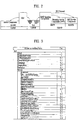
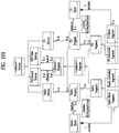
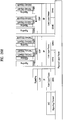
- FIG. 1 illustrates a receiver protocol stack according to an embodiment of the present invention.
- Two schemes may be used in broadcast service delivery through a broadcast network.
- MPUs media processing units
- MMT MPEG media transport
- DASH dynamic adaptive streaming over HTTP
- ROUTE real time object delivery over unidirectional transport
- Non-timed content including NRT media, EPG data, and other files is delivered with ROUTE.
- Signaling may be delivered over MMTP and/or ROUTE, while bootstrap signaling information is provided by the means of the Service List Table (SLT).
- SLT Service List Table
- hybrid service delivery MPEG DASH over HTTP/TCP/IP is used on the broadband side.
- Media files in ISO Base Media File Format (BMFF) are used as the delivery, media encapsulation and synchronization format for both broadcast and broadband delivery.
- BMFF ISO Base Media File Format
- hybrid service delivery may refer to a case in which one or more program elements are delivered through a broadband path.
- Services are delivered using three functional layers. These are the physical layer, the delivery layer and the service management layer.
- the physical layer provides the mechanism by which signaling, service announcement and IP packet streams are transported over the broadcast physical layer and/or broadband physical layer.
- the delivery layer provides object and object flow transport functionality. It is enabled by the MMTP or the ROUTE protocol, operating on a UDP/IP multicast over the broadcast physical layer, and enabled by the HTTP protocol on a TCP/IP unicast over the broadband physical layer.
- the service management layer enables any type of service, such as linear TV or HTML5 application service, to be carried by the underlying delivery and physical layers.
- a protocol stack part on a broadcast side may be divided into a part transmitted through the SLT and the MMTP, and a part transmitted through ROUTE.
- the SLT may be encapsulated through UDP and IP layers.
- the SLT will be described below.
- the MMTP may transmit data formatted in an MPU format defined in MMT, and signaling information according to the MMTP.
- the data may be encapsulated through the UDP and IP layers.
- ROUTE may transmit data formatted in a DASH segment form, signaling information, and non-timed data such as NRT data, etc.
- the data may be encapsulated through the UDP and IP layers. According to a given embodiment, some or all processing according to the UDP and IP layers may be omitted.
- the illustrated signaling information may be signaling information related to a service.
- the part transmitted through the SLT and the MMTP and the part transmitted through ROUTE may be processed in the UDP and IP layers, and then encapsulated again in a data link layer.
- the link layer will be described below. Broadcast data processed in the link layer may be multicast as a broadcast signal through processes such as encoding/interleaving, etc. in the physical layer.
- a protocol stack part on a broadband side may be transmitted through HTTP as described above.
- Data formatted in a DASH segment form, signaling information, NRT information, etc. may be transmitted through HTTP.
- the illustrated signaling information may be signaling information related to a service.
- the data may be processed through the TCP layer and the IP layer, and then encapsulated into the link layer. According to a given embodiment, some or all of the TCP, the IP, and the link layer may be omitted. Broadband data processed thereafter may be transmitted by unicast in the broadband through a process for transmission in the physical layer.
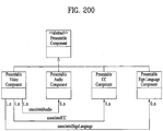
- Service can be a collection of media components presented to the user in aggregate; components can be of multiple media types; a Service can be either continuous or intermittent; a Service can be Real Time or Non-Real Time; Real Time Service can consist of a sequence of TV programs.
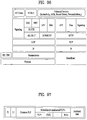
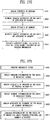
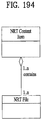
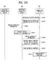
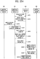
- FIG. 2 illustrates a relation between the SLT and SLS according to an embodiment of the present invention.
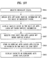
- Service signaling provides service discovery and description information, and comprises two functional components: Bootstrap signaling via the Service List Table (SLT) and the Service Layer Signaling (SLS). These represent the information which is necessary to discover and acquire user services.
- SLT Service List Table
- SLS Service Layer Signaling
- the SLT can enable very rapid acquisition of basic service information.
- the SLS enables the receiver to discover and access services and their content components. Details of the SLT and SLS will be described below.
- the SLT may be transmitted through UDP/IP.
- data corresponding to the SLT may be delivered through the most robust scheme in this transmission.
- the SLT may have access information for accessing SLS delivered by the ROUTE protocol.
- the SLT may be bootstrapped into SLS according to the ROUTE protocol.
- the SLS is signaling information positioned in an upper layer of ROUTE in the above-described protocol stack, and may be delivered through ROUTE/UDP/IP.
- the SLS may be transmitted through one of LCT sessions included in a ROUTE session. It is possible to access a service component corresponding to a desired service using the SLS.
- the SLT may have access information for accessing an MMT signaling component delivered by MMTP.
- the SLT may be bootstrapped into SLS according to the MMTP.
- the SLS may be delivered by an MMTP signaling message defined in MMT. It is possible to access a streaming service component (MPU) corresponding to a desired service using the SLS.
- MPU streaming service component
- an NRT service component is delivered through the ROUTE protocol, and the SLS according to the MMTP may include information for accessing the ROUTE protocol.
- broadband delivery the SLS is carried over HTTP(S)/TCP/IP.
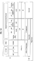
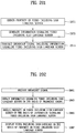
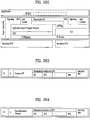
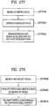
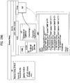
- FIG. 3 illustrates an SLT according to an embodiment of the present invention.
- Services may be signaled as being one of two basic types.
- First type is a linear audio/video or audio-only service that may have an app-based enhancement.
- Second type is a service whose presentation and composition is controlled by a downloaded application that is executed upon acquisition of the service. The latter can be called an "app-based" service.
- the rules regarding presence of ROUTE/LCT sessions and/or MMTP sessions for carrying the content components of a service may be as follows.
- the service's content components can be carried by either (but not both): (1) one or more ROUTE/LCT sessions, or (2) one or more MMTP sessions.
- the service's content components can be carried by: (1) one or more ROUTE/LCT sessions, and (2) zero or more MMTP sessions.
- use of both MMTP and ROUTE for streaming media components in the same service may not be allowed.
- the service's content components can be carried by one or more ROUTE/LCT sessions.
- Each ROUTE session comprises one or more LCT sessions which carry as a whole, or in part, the content components that make up the service.
- an LCT session may carry an individual component of a user service such as an audio, video or closed caption stream.
- Streaming media is formatted as DASH Segments.
- Each MMTP session comprises one or more MMTP packet flows which carry MMT signaling messages or as a whole, or in part, the content component.
- An MMTP packet flow may carry MMT signaling messages or components formatted as MPUs.
- an LCT session For the delivery of NRT User Services or system metadata, an LCT session carries file-based content items. These content files may consist of continuous (time-based) or discrete (non-time-based) media components of an NRT service, or metadata such as Service Signaling or ESG fragments. Delivery of system metadata such as service signaling or ESG fragments may also be achieved through the signaling message mode of MMTP.
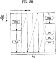
- a broadcast stream is the abstraction for an RF channel, which is defined in terms of a carrier frequency centered within a specified bandwidth. It is identified by the pair [geographic area, frequency].
- a physical layer pipe corresponds to a portion of the RF channel. Each PLP has certain modulation and coding parameters. It is identified by a PLP identifier (PLPID), which is unique within the broadcast stream it belongs to.
- PLP can be referred to as DP (data pipe).
- Each service is identified by two forms of service identifier: a compact form that is used in the SLT and is unique only within the broadcast area; and a globally unique form that is used in the SLS and the ESG.
- a ROUTE session is identified by a source IP address, destination IP address and destination port number.
- An LCT session (associated with the service component(s) it carries) is identified by a transport session identifier (TSI) which is unique within the scope of the parent ROUTE session.
- TSI transport session identifier
- Properties common to the LCT sessions, and certain properties unique to individual LCT sessions, are given in a ROUTE signaling structure called a service-based transport session instance description (S-TSID), which is part of the service layer signaling.
- S-TSID service-based transport session instance description
- one LCT session may be transmitted through a plurality of PLPs.
- Different LCT sessions of a ROUTE session may or may not be contained in different physical layer pipes.
- the ROUTE session may be delivered through a plurality of PLPs.
- the properties described in the S-TSID include the TSI value and PLPID for each LCT session, descriptors for the delivery objects/files, and application layer FEC parameters.
- a MMTP session is identified by destination IP address and destination port number.
- An MMTP packet flow (associated with the service component(s) it carries) is identified by a packet_id which is unique within the scope of the parent MMTP session.
- Properties common to each MMTP packet flow, and certain properties of MMTP packet flows, are given in the SLT.
- Properties for each MMTP session are given by MMT signaling messages, which may be carried within the MMTP session. Different MMTP packet flows of a MMTP session may or may not be contained in different physical layer pipes.
- the MMTP session may be delivered through a plurality of PLPs.
- the properties described in the MMT signaling messages include the packet_id value and PLPID for each MMTP packet flow.
- the MMT signaling messages may have a form defined in MMT, or have a deformed form according to embodiments to be described below.
- LLC low level signaling
- LLS low level signaling
- the IP address and the port number may be differently configured depending on embodiments.
- LLS can be transported in IP packets with address 224.0.23.60 and destination port 4937/udp.
- LLS may be positioned in a portion expressed by "SLT" on the above-described protocol stack.
- the LLS may be transmitted through a separate physical channel (dedicated channel) in a signal frame without being subjected to processing of the UDP/IP layer.
- UDP/IP packets that deliver LLS data may be formatted in a form referred to as an LLS table.
- a first byte of each UDP/IP packet that delivers the LLS data may correspond to a start of the LLS table.
- the maximum length of any LLS table is limited by the largest IP packet that can be delivered from the PHY layer, 65,507 bytes.
- the LLS table may include an LLS table ID field that identifies a type of the LLS table, and an LLS table version field that identifies a version of the LLS table. According to a value indicated by the LLS table ID field, the LLS table may include the above-described SLT or a rating region table (RRT). The RRT may have information about content advisory rating.
- LLS can be signaling information which supports rapid channel scans and bootstrapping of service acquisition by the receiver
- SLT can be a table of signaling information which is used to build a basic service listing and provide bootstrap discovery of SLS.
- SLT The function of the SLT is similar to that of the program association table (PAT) in MPEG-2 Systems, and the fast information channel (FIC) found in ATSC Systems. For a receiver first encountering the broadcast emission, this is the place to start.
- SLT supports a rapid channel scan which allows a receiver to build a list of all the services it can receive, with their channel name, channel number, etc., and SLT provides bootstrap information that allows a receiver to discover the SLS for each service.
- the bootstrap information includes the destination IP address and destination port of the LCT session that carries the SLS.
- MMT/MPU-delivered services the bootstrap information includes the destination IP address and destination port of the MMTP session carrying the SLS.
- the SLT supports rapid channel scans and service acquisition by including the following information about each service in the broadcast stream.
- the SLT can include information necessary to allow the presentation of a service list that is meaningful to viewers and that can support initial service selection via channel number or up/down selection.
- the SLT can include information necessary to locate the service layer signaling for each service listed. That is, the SLT may include access information related to a location at which the SLS is delivered.
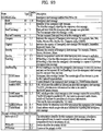
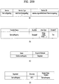
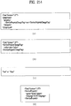
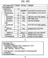
- the illustrated SLT according to the present embodiment is expressed as an XML document having an SLT root element.
- the SLT may be expressed in a binary format or an XML document.
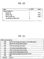
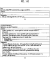
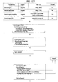
- the SLT root element of the SLT illustrated in the figure may include @bsid, @sltSectionVersion, @sltSectionNumber, @totalSltSectionNumbers, @language, @capabilities, InetSigLoc and/or Service. According to a given embodiment, the SLT root element may further include @providerId. According to a given embodiment, the SLT root element may not include @language.
- the service element may include @serviceId, @SLTserviceSeqNumber, @protected, @majorChannelNo, @minorChannelNo, @serviceCategory, @shortServiceName, @hidden, @slsProtocolType, BroadcastSignaling, @slsPlpId, @slsDestinationIpAddress, @slsDestinationUdpPort, @slsSourceIpAddress, @slsMajorProtocolVersion, @SlsMinorProtocolVersion, @serviceLanguage, @broadbandAccessRequired, @capabilities and/or InetSigLoc.
- an attribute or an element of the SLT may be added/changed/deleted.
- Each element included in the SLT may additionally have a separate attribute or element, and some attribute or elements according to the present embodiment may be omitted.
- a field which is marked with @ may correspond to an attribute, and a field which is not marked with @ may correspond to an element.
- @bsid is an identifier of the whole broadcast stream.
- the value of BSID may be unique on a regional level.
- @providerId can be an index of broadcaster that is using part or all of this broadcast stream. This is an optional attribute. When it's not present, it means that this broadcast stream is being used by one broadcaster. @providerId is not illustrated in the figure.
- @sltSectionVersion can be a version number of the SLT section.
- the sltSectionVersion can be incremented by 1 when a change in the information carried within the slt occurs. When it reaches maximum value, it wraps around to 0.
- @sltSectionNumber can be the number, counting from 1, of this section of the SLT. In other words, @sltSectionNumber may correspond to a section number of the SLT section. When this field is not used, @sltSectionNumber may be set to a default value of 1.
- @totalSltSectionNumbers can be the total number of sections (that is, the section with the highest sltSectionNumber) of the SLT of which this section is part. sltSectionNumber and totalSltSectionNumbers together can be considered to indicate "Part M of N" of one portion of the SLT when it is sent in fragments. In other words, when the SLT is transmitted, transmission through fragmentation may be supported. When this field is not used, @totalSltSectionNumbers may be set to a default value of 1. A case in which this field is not used may correspond to a case in which the SLT is not transmitted by being fragmented.
- @language can indicate primary language of the services included in this slt instance.
- a value of this field may have a three-character language code defined in the ISO. This field may be omitted.
- @capabilities can indicate required capabilities for decoding and meaningfully presenting the content for all the services in this slt instance.
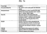
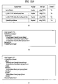
- InetSigLoc can provide a URL telling the receiver where it can acquire any requested type of data from external server(s) via broadband.
- This element may include @urlType as a lower field.
- a type of a URL provided by InetSigLoc may be indicated.
- InetSigLoc may provide a URL of a signaling server.
- InetSigLoc may provide a URL of an ESG server.
- the @urlType field has other values, the field may be reserved for future use.
- the service field is an element having information about each service, and may correspond to a service entry.
- Service element fields corresponding to the number of services indicated by the SLT may be present.
- a description will be given of a lower attribute/element of the service field.
- @serviceId can be an integer number that uniquely identify this service within the scope of this broadcast area. According to a given embodiment, a scope of @serviceId may be changed.
- @SLTserviceSeqNumber can be an integer number that indicates the sequence number of the SLT service information with service ID equal to the serviceId attribute above.
- SLTserviceSeqNumber value can start at 0 for each service and can be incremented by 1 every time any attribute in this service element is changed. If no attribute values are changed compared to the previous Service element with a particular value of ServiceID then SLTserviceSeqNumber would not be incremented. The SLTserviceSeqNumber field wraps back to 0 after reaching the maximum value.
- @protected is flag information which may indicate whether one or more components for significant reproduction of the service are in a protected state. When set to "1" (true), that one or more components necessary for meaningful presentation is protected. When set to "0" (false), this flag indicates that no components necessary for meaningful presentation of the service are protected. Default value is false.
- @majorChannelNo is an integer number representing the "major" channel number of the service.
- An example of the field may have a range of 1 to 999.
- @minorChannelNo is an integer number representing the "minor" channel number of the service.
- An example of the field may have a range of 1 to 999.
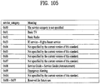
- @serviceCategory can indicate the category of this service.
- This field may indicate a type that varies depending on embodiments. According to a given embodiment, when this field has values of 1, 2, and 3, the values may correspond to a linear A/V service, a linear audio only service, and an app-based service, respectively. When this field has a value of 0, the value may correspond to a service of an undefined category. When this field has other values except for 1, 2, and 3, the field may be reserved for future use.
- @shortServiceName can be a short string name of the Service.
- @hidden can be boolean value that when present and set to "true” indicates that the service is intended for testing or proprietary use, and is not to be selected by ordinary TV receivers. The default value is "false” when not present.
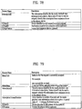
- @slsProtocolType can be an attribute indicating the type of protocol of Service Layer Signaling used by this service. This field may indicate a type that varies depending on embodiments. According to a given embodiment, when this field has values of 1 and 2, protocols of SLS used by respective corresponding services may be ROUTE and MMTP, respectively. When this field has other values except for 0, the field may be reserved for future use. This field may be referred to as @slsProtocol.
- BroadcastSignaling and lower attributes/elements thereof may provide information related to broadcast signaling.
- the BroadcastSignaling element When the BroadcastSignaling element is not present, the child element InetSigLoc of the parent service element can be present and its attribute urlType includes URL_type 0x00 (URL to signaling server).
- the element InetSigLoc can be present as a child element of the slt root element and the attribute urlType of that InetSigLoc element includes URL_type 0x00 (URL to signaling server).
- @slsPlpId can be a string representing an integer number indicating the PLP ID of the physical layer pipe carrying the SLS for this service.
- @slsDestinationIpAddress can be a string containing the dotted-IPv4 destination address of the packets carrying SLS data for this service.
- @slsDestinationUdpPort can be a string containing the port number of the packets carrying SLS data for this service. As described in the foregoing, SLS bootstrapping may be performed by destination IP/UDP information.
- @slsSourceIpAddress can be a string containing the dotted-IPv4 source address of the packets carrying SLS data for this service.
- @slsMajorProtocolVersion can be major version number of the protocol used to deliver the service layer signaling for this service. Default value is 1.
- @SlsMinorProtocolVersion can be minor version number of the protocol used to deliver the service layer signaling for this service. Default value is 0.
- @serviceLanguage can be a three-character language code indicating the primary language of the service.
- a value of this field may have a form that varies depending on embodiments.
- @broadbandAccessRequired can be a Boolean indicating that broadband access is required for a receiver to make a meaningful presentation of the service. Default value is false. When this field has a value of True, the receiver needs to access a broadband for significant service reproduction, which may correspond to a case of hybrid service delivery.
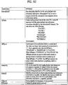
- @capabilities can represent required capabilities for decoding and meaningfully presenting the content for the service with service ID equal to the service Id attribute above.
- InetSigLoc can provide a URL for access to signaling or announcement information via broadband, if available. Its data type can be an extension of the any URL data type, adding an @urlType attribute that indicates what the URL gives access to.
- An @urlType field of this field may indicate the same meaning as that of the @urlType field of InetSigLoc described above.
- an InetSigLoc element of attribute URL_type 0x00 is present as an element of the SLT, it can be used to make HTTP requests for signaling metadata.
- the HTTP POST message body may include a service term. When the InetSigLoc element appears at the section level, the service term is used to indicate the service to which the requested signaling metadata objects apply.
- the signaling metadata objects for all services in the section are requested.
- the InetSigLoc appears at the service level, then no service term is needed to designate the desired service.
- an InetSigLoc element of attribute URL_type 0x01 is provided, it can be used to retrieve ESG data via broadband. If the element appears as a child element of the service element, then the URL can be used to retrieve ESG data for that service. If the element appears as a child element of the SLT element, then the URL can be used to retrieve ESG data for all services in that section.
- @sltSectionVersion, @sltSectionNumber, @totalSltSectionNumbers and/or @language fields of the SLT may be omitted
- InetSigLoc field may be replaced by @sltInetSigUri and/or @sltInetEsgUri field.
- the two fields may include the URI of the signaling server and URI information of the ESG server, respectively.
- the InetSigLoc field corresponding to a lower field of the SLT and the InetSigLoc field corresponding to a lower field of the service field may be replaced in a similar manner.
- the suggested default values may vary depending on embodiments.
- An illustrated "use” column relates to the respective fields.
- “1” may indicate that a corresponding field is an essential field
- "0..1” may indicate that a corresponding field is an optional field.
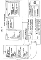
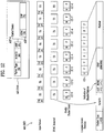
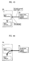
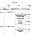
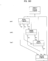
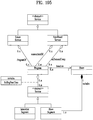
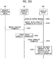
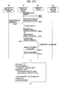
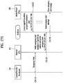
- FIG. 4 illustrates SLS bootstrapping and a service discovery process according to an embodiment of the present invention.
- SLS can be signaling which provides information for discovery and acquisition of services and their content components.
- the SLS for each service describes characteristics of the service, such as a list of its components and where to acquire them, and the receiver capabilities required to make a meaningful presentation of the service.
- the SLS includes the user service bundle description (USBD), the S-TSID and the DASH media presentation description (MPD).
- USBD or user service description (USD) is one of SLS XML fragments, and may function as a signaling herb that describes specific descriptive information.
- USBD/USD may be extended beyond 3GPP MBMS. Details of USBD/USD will be described below.
- the service signaling focuses on basic attributes of the service itself, especially those attributes needed to acquire the service. Properties of the service and programming that are intended for viewers appear as service announcement, or ESG data.
- the SLT can include HTTP URLs where the Service Signaling files can be obtained, as described above.
- LLS is used for bootstrapping SLS acquisition, and subsequently, the SLS is used to acquire service components delivered on either ROUTE sessions or MMTP sessions.
- the described figure illustrates the following signaling sequences.
- Receiver starts acquiring the SLT described above.
- Each service identified by service_id delivered over ROUTE sessions provides SLS bootstrapping information: PLPID(#1), source IP address (sIP1), destination IP address (dIP1), and destination port number (dPort1).
- SLS bootstrapping information PLPID(#2), destination IP address (dIP2), and destination port number (dPort2).
- the receiver can acquire SLS fragments carried over the IP/UDP/LCT session and PLP; whereas for streaming services delivery using MMTP, the receiver can acquire SLS fragments carried over an MMTP session and PLP.
- these SLS fragments include USBD/USD fragments, S-TSID fragments, and MPD fragments. They are relevant to one service.
- USBD/USD fragments describe service layer properties and provide URI references to S-TSID fragments and URI references to MPD fragments. In other words, the USBD/USD may refer to S-TSID and MPD.
- the USBD references the MMT signaling's MPT message, the MP Table of which provides identification of package ID and location information for assets belonging to the service.
- an asset is a multimedia data entity, and may refer to a data entity which is combined into one unique ID and is used to generate one multimedia presentation.
- the asset may correspond to a service component included in one service.
- the MPT message is a message having the MP table of MMT.
- the MP table may be an MMT package table having information about content and an MMT asset. Details may be similar to a definition in MMT.
- media presentation may correspond to a collection of data that establishes bounded/unbounded presentation of media content.
- the S-TSID fragment provides component acquisition information associated with one service and mapping between DASH Representations found in the MPD and in the TSI corresponding to the component of the service.
- the S-TSID can provide component acquisition information in the form of a TSI and the associated DASH representation identifier, and PLPID carrying DASH segments associated with the DASH representation.
- the receiver collects the audio/video components from the service and begins buffering DASH media segments then applies the appropriate decoding processes.
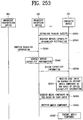
- the receiver For USBD listing service components delivered on MMTP sessions, as illustrated by "Service #2" in the described figure, the receiver also acquires an MPT message with matching MMT_package_id to complete the SLS.
- An MPT message provides the full list of service components comprising a service and the acquisition information for each component.
- Component acquisition information includes MMTP session information, the PLPID carrying the session and the packet_id within that session.
- each S-TSID fragment may be used.
- Each fragment may provide access information related to LCT sessions delivering content of each service.
- S-TSID, USBD/USD, MPD, or an LCT session delivering S-TSID, USBD/USD or MPD may be referred to as a service signaling channel.
- S-TSID, USBD/USD, MPD, or an LCT session delivering S-TSID, USBD/USD or MPD may be referred to as a service signaling channel.
- MMTP, USBD/UD, an MMT signaling message, or a packet flow delivering the MMTP or USBD/UD may be referred to as a service signaling channel.
- one ROUTE or MMTP session may be delivered through a plurality of PLPs.
- one service may be delivered through one or more PLPs.
- one LCT session may be delivered through one PLP.
- components included in one service may be delivered through different ROUTE sessions.
- components included in one service may be delivered through different MMTP sessions.
- components included in one service may be delivered separately through a ROUTE session and an MMTP session.
- components included in one service may be delivered via broadband (hybrid delivery).
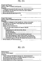
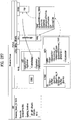
- FIG. 5 illustrates a USBD fragment for ROUTE/DASH according to an embodiment of the present invention.
- SLS provides detailed technical information to the receiver to enable the discovery and access of services and their content components. It can include a set of XML-encoded metadata fragments carried over a dedicated LCT session. That LCT session can be acquired using the bootstrap information contained in the SLT as described above.
- the SLS is defined on a per-service level, and it describes the characteristics and access information of the service, such as a list of its content components and how to acquire them, and the receiver capabilities required to make a meaningful presentation of the service.
- the SLS consists of the following metadata fragments: USBD, S-TSID and the DASH MPD.
- a TSI of a particular LCT session (dedicated LCT session) in which an SLS fragment is delivered may have a different value.
- an LCT session in which an SLS fragment is delivered may be signaled using the SLT or another scheme.
- ROUTE/DASH SLS can include the user service bundle description (USBD) and service-based transport session instance description (S-TSID) metadata fragments. These service signaling fragments are applicable to both linear and application-based services.
- the USBD fragment contains service identification, device capabilities information, references to other SLS fragments required to access the service and constituent media components, and metadata to enable the receiver to determine the transport mode (broadcast and/or broadband) of service components.
- the S-TSID fragment referenced by the USBD, provides transport session descriptions for the one or more ROUTE/LCT sessions in which the media content components of a service are delivered, and descriptions of the delivery objects carried in those LCT sessions.
- the USBD and S-TSID will be described below.
- a streaming content signaling component of SLS corresponds to an MPD fragment.
- the MPD is typically associated with linear services for the delivery of DASH Segments as streaming content.
- the MPD provides the resource identifiers for individual media components of the linear/streaming service in the form of Segment URLs, and the context of the identified resources within the Media Presentation. Details of the MPD will be described below.
- app-based enhancement signaling in ROUTE-based delivery, pertains to the delivery of app-based enhancement components, such as an application logic file, locally-cached media files, network content items, or a notification stream.
- app-based enhancement components such as an application logic file, locally-cached media files, network content items, or a notification stream.
- An application can also retrieve locally-cached data over a broadband connection when available.
- USBD/USD illustrated in the figure.
- the top level or entry point SLS fragment is the USBD fragment.
- An illustrated USBD fragment is an example of the present invention, basic fields of the USBD fragment not illustrated in the figure may be additionally provided according to a given embodiment. As described in the foregoing, the illustrated USBD fragment has an extended form, and may have fields added to a basic configuration.
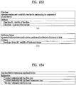
- the illustrated USBD may have a bundleDescription root element.
- the bundleDescription root element may have a userServiceDescription element.
- the userServiceDescription element may correspond to an instance for one service.
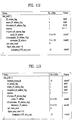
- the userServiceDescription element may include @serviceId, @atsc:serviceId, @atsc:serviceStatus, @atsc:fullMPDUri, @atsc:sTSIDUri, name, serviceLanguage, atsc:capabilityCode and/or deliveryMethod.
- @serviceId can be a globally unique URI that identifies a service, unique within the scope of the BSID. This parameter can be used to link to ESG data (Service@globalServiceID).
- @atsc:serviceId is a reference to corresponding service entry in LLS(SLT). The value of this attribute is the same value of serviceId assigned to the entry.
- @atsc:serviceStatus can specify the status of this service. The value indicates whether this service is active or inactive. When set to "1" (true), that indicates service is active. When this field is not used, @atsc:serviceStatus may be set to a default value of 1.
- @atsc:fullMPDUri can reference an MPD fragment which contains descriptions for contents components of the service delivered over broadcast and optionally, also over broadband.
- @atsc:sTSIDUri can reference the S-TSID fragment which provides access related parameters to the Transport sessions carrying contents of this service.
- name can indicate name of the service as given by the lang attribute.
- name element can include lang attribute, which indicating language of the service name.
- the language can be specified according to XML data types.
- serviceLanguage can represent available languages of the service.
- the language can be specified according to XML data types.
- Atsc:capabilityCode can specify the capabilities required in the receiver to be able to create a meaningful presentation of the content of this service.
- this field may specify a predefined capability group.
- the capability group may be a group of capability attribute values for significant presentation. This field may be omitted according to a given embodiment.
- the deliveryMethod can be a container of transport related information pertaining to the contents of the service over broadcast and (optionally) broadband modes of access. Referring to data included in the service, when the number of the data is N, delivery schemes for respective data may be described by this element.
- the deliveryMethod may include an r12:broadcastAppService element and an r12:unicastAppService element. Each lower element may include a basePattern element as a lower element.
- r12:broadcastAppService can be a DASH Representation delivered over broadcast, in multiplexed or non-multiplexed form, containing the corresponding media component(s) belonging to the service, across all Periods of the affiliated media presentation.
- each of the fields may indicate DASH representation delivered through the broadcast network.
- r12:unicastAppService can be a DASH Representation delivered over broadband, in multiplexed or non-multiplexed form, containing the constituent media content component(s) belonging to the service, across all periods of the affiliated media presentation.
- each of the fields may indicate DASH representation delivered via broadband.
- basePattern can be a character pattern for use by the receiver to match against any portion of the segment URL used by the DASH client to request media segments of a parent representation under its containing period.
- a match implies that the corresponding requested media segment is carried over broadcast transport.
- a URL address for receiving DASH representation expressed by each of the r12:broadcastAppService element and the r12:unicastAppService element a part of the URL, etc. may have a particular pattern. The pattern may be described by this field. Some data may be distinguished using this information.
- the proposed default values may vary depending on embodiments.
- the "use" column illustrated in the figure relates to each field.
- M may denote an essential field
- O may denote an optional field
- OD may denote an optional field having a default value
- CM may denote a conditional essential field.
- 0...1 to 0...N may indicate the number of available fields.
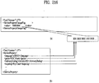
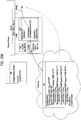
- FIG. 6 illustrates an S-TSID fragment for ROUTE/DASH according to an embodiment of the present invention.
- S-TSID can be an SLS XML fragment which provides the overall session description information for transport session(s) which carry the content components of a service.
- the S-TSID is the SLS metadata fragment that contains the overall transport session description information for the zero or more ROUTE sessions and constituent LCT sessions in which the media content components of a service are delivered.
- the S-TSID also includes file metadata for the delivery object or object flow carried in the LCT sessions of the service, as well as additional information on the payload formats and content components carried in those LCT sessions.
- Each instance of the S-TSID fragment is referenced in the USBD fragment by the @atsc:sTSIDUri attribute of the userServiceDescription element.
- the illustrated S-TSID according to the present embodiment is expressed as an XML document. According to a given embodiment, the S-TSID may be expressed in a binary format or as an XML document.
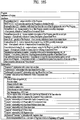
- the illustrated S-TSID may have an S-TSID root element.
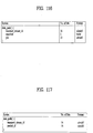
- the S-TSID root element may include @serviceId and/or RS.
- @serviceID can be a reference corresponding service element in the USD.
- the value of this attribute can reference a service with a corresponding value of service_id.
- the RS element may have information about a ROUTE session for delivering the service data.
- Service data or service components may be delivered through a plurality of ROUTE sessions, and thus the number of RS elements may be 1 to N.
- the RS element may include @bsid, @sIpAddr, @dIpAddr, @dport, @PLPID and/or LS.
- @bsid can be an identifier of the broadcast stream within which the content component(s) of the broadcastAppService are carried.
- the default broadcast stream is the one whose PLPs carry SLS fragments for this service. Its value can be identical to that of the broadcast_stream_id in the SLT.
- @sIpAddr can indicate source IP address.
- the source IP address may be a source IP address of a ROUTE session for delivering a service component included in the service.
- service components of one service may be delivered through a plurality of ROUTE sessions.
- the service components may be transmitted using another ROUTE session other than the ROUTE session for delivering the S-TSID. Therefore, this field may be used to indicate the source IP address of the ROUTE session.
- a default value of this field may be a source IP address of a current ROUTE session.
- a value of this field may be a value of a source IP address of the ROUTE session. In this case, this field may correspond to M, that is, an essential field.
- @dIpAddr can indicate destination IP address.
- a destination IP address may be a destination IP address of a ROUTE session that delivers a service component included in a service.
- this field may indicate a destination IP address of a ROUTE session that delivers a service component.
- a default value of this field may be a destination IP address of a current ROUTE session.
- a value of this field may be a value of a destination IP address of the ROUTE session.
- this field may correspond to M, that is, an essential field.
- @dport can indicate destination port.
- a destination port may be a destination port of a ROUTE session that delivers a service component included in a service.
- this field may indicate a destination port of a ROUTE session that delivers a service component.
- a default value of this field may be a destination port number of a current ROUTE session.
- a value of this field may be a destination port number value of the ROUTE session. In this case, this field may correspond to M, that is, an essential field.
- @PLPID may be an ID of a PLP for a ROUTE session expressed by an RS.
- a default value may be an ID of a PLP of an LCT session including a current S-TSID.
- this field may have an ID value of a PLP for an LCT session for delivering an S-TSID in the ROUTE session, and may have ID values of all PLPs for the ROUTE session.
- An LS element may have information about an LCT session for delivering a service data.
- Service data or service components may be delivered through a plurality of LCT sessions, and thus the number of LS elements may be 1 to N.
- the LS element may include @tsi, @PLPID, @bw, @startTime, @endTime, SrcFlow and/or RprFlow.
- @tsi may indicate a TSI value of an LCT session for delivering a service component of a service.
- @PLPID may have ID information of a PLP for the LCT session. This value may be overwritten on a basic ROUTE session value.
- @bw may indicate a maximum bandwidth value.
- @startTime may indicate a start time of the LCT session.
- @endTime may indicate an end time of the LCT session.
- a SrcFlow element may describe a source flow of ROUTE.
- a RprFlow element may describe a repair flow of ROUTE.
- the proposed default values may be varied according to an embodiment.
- the "use" column illustrated in the figure relates to each field.
- M may denote an essential field
- O may denote an optional field
- OD may denote an optional field having a default value
- CM may denote a conditional essential field.
- 0...1 to 0...N may indicate the number of available fields.
- the MPD is an SLS metadata fragment which contains a formalized description of a DASH Media Presentation, corresponding to a linear service of a given duration defined by the broadcaster (for example a single TV program, or the set of contiguous linear TV programs over a period of time).
- the contents of the MPD provide the resource identifiers for Segments and the context for the identified resources within the Media Presentation.
- the data structure and semantics of the MPD fragment can be according to the MPD defined by MPEG DASH.
- One or more of the DASH Representations conveyed in the MPD can be carried over broadcast.
- the MPD may describe additional Representations delivered over broadband, e.g. in the case of a hybrid service, or to support service continuity in handoff from broadcast to broadcast due to broadcast signal degradation (e.g. driving through a tunnel).
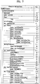
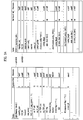
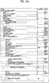
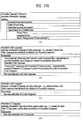
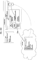
- FIG. 7 illustrates a USBD/USD fragment for MMT according to an embodiment of the present invention.
- MMT SLS for linear services comprises the USBD fragment and the MMT Package (MP) table.
- the MP table is as described above.
- the USBD fragment contains service identification, device capabilities information, references to other SLS information required to access the service and constituent media components, and the metadata to enable the receiver to determine the transport mode (broadcast and/or broadband) of the service components.
- the MP table for MPU components referenced by the USBD, provides transport session descriptions for the MMTP sessions in which the media content components of a service are delivered and the descriptions of the Assets carried in those MMTP sessions.
- the streaming content signaling component of the SLS for MPU components corresponds to the MP table defined in MMT.
- the MP table provides a list of MMT assets where each asset corresponds to a single service component and the description of the location information for this component.
- USBD fragments may also contain references to the S-TSID and the MPD as described above, for service components delivered by the ROUTE protocol and the broadband, respectively.
- a service component delivered through the ROUTE protocol is NRT data, etc.
- MPD may be unnecessary.
- information about an LCT session for delivering a service component, which is delivered via broadband is unnecessary, and thus an S-TSID may be unnecessary.
- an MMT package may be a logical collection of media data delivered using MMT.
- an MMTP packet may refer to a formatted unit of media data delivered using MMT.
- An MPU may refer to a generic container of independently decodable timed/non-timed data.
- data in the MPU is media codec agnostic.
- the illustrated USBD fragment is an example of the present invention, and basic fields of the USBD fragment may be additionally provided according to an embodiment. As described in the foregoing, the illustrated USBD fragment has an extended form, and may have fields added to a basic structure.
- the illustrated USBD is expressed as an XML document. According to a given embodiment, the USBD may be expressed in a binary format or as an XML document.
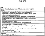
- the illustrated USBD may have a bundleDescription root element.
- the bundleDescription root element may have a userServiceDescription element.
- the userServiceDescription element may be an instance for one service.
- the userServiceDescription element may include @serviceId, @atsc:serviceId, name, serviceLanguage, atsc:capabilityCode, atsc:Channel, atsc:mpuComponent, atsc:routeComponent, atsc:broadbandComponent and/or atsc:ComponentInfo.
- @serviceId, @atsc:serviceId, name, serviceLanguage, and atsc:capabilityCode may be as described above.
- the lang field below the name field may be as described above.
- atsc:capabilityCode may be omitted according to a given embodiment.
- the userServiceDescription element may further include an atsc:contentAdvisoryRating element according to an embodiment.
- This element may be an optional element.
- atsc:contentAdvisoryRating can specify the content advisory rating. This field is not illustrated in the figure.
- Atsc:Channel may have information about a channel of a service.
- the atsc:Channel element may include @atsc:majorChannelNo, @atsc:minorChannelNo, @atsc:serviceLang, @atsc:serviceGenre, @atsc:serviceIcon and/or atsc:ServiceDescription.
- @atsc:majorChannelNo, @atsc:minorChannelNo, and @atsc:serviceLang may be omitted according to a given embodiment.
- @atsc:majorChannelNo is an attribute that indicates the major channel number of the service.
- @atsc:minorChannelNo is an attribute that indicates the minor channel number of the service.
- @atsc:serviceLang is an attribute that indicates the primary language used in the service.
- @atsc:serviceGenre is an attribute that indicates primary genre of the service.
- @atsc:serviceIcon is an attribute that indicates the Uniform Resource Locator (URL) for the icon used to represent this service.
- Atsc:ServiceDescription includes service description, possibly in multiple languages.
- atsc:ServiceDescription includes can include @atsc:serviceDescrText and/or @atsc:serviceDescrLang.
- @atsc:serviceDescrText is an attribute that indicates description of the service.
- @atsc:serviceDescrLang is an attribute that indicates the language of the serviceDescrText attribute above.
- Atsc:mpuComponent may have information about a content component of a service delivered in a form of an MPU.
- atsc:mpuComponent may include @atsc:mmtPackageId and/or @atsc:nextMmtPackageId.
- @atsc:mmtPackageId can reference a MMT Package for content components of the service delivered as MPUs.
- @atsc:nextMmtPackageId can reference a MMT Package to be used after the one referenced by @atsc:mmtPackageId in time for content components of the service delivered as MPUs.
- Atsc:routeComponent may have information about a content component of a service delivered through ROUTE.
- atsc:routeComponent may include @atsc:sTSIDUri, @sTSIDP1pId, @sTSIDDestinationIpAddress, @sTSIDDestinationUdpPort, @sTSIDSourceIpAddress, @sTSIDMajorProtocolVersion and/or @sTSIDMinorProtocolVersion.
- @atsc:sTSIDUri can be a reference to the S-TSID fragment which provides access related parameters to the Transport sessions carrying contents of this service.
- This field may be the same as a URI for referring to an S-TSID in USBD for ROUTE described above.
- service components which are delivered through NRT, etc., may be delivered by ROUTE. This field may be used to refer to the S-TSID therefor.
- @sTSIDP1pId can be a string representing an integer number indicating the PLP ID of the physical layer pipe carrying the S-TSID for this service. (default: current physical layer pipe).
- @sTSIDDestinationIpAddress can be a string containing the dotted-IPv4 destination address of the packets carrying S-TSID for this service. (default: current MMTP session's source IP address)
- @sTSIDDestinationUdpPort can be a string containing the port number of the packets carrying S-TSID for this service.
- @sTSIDSourceIpAddress can be a string containing the dotted-IPv4 source address of the packets carrying S-TSID for this service.
- @sTSIDMajorProtocolVersion can indicate major version number of the protocol used to deliver the S-TSID for this service. Default value is 1.
- @sTSIDMinorProtocolVersion can indicate minor version number of the protocol used to deliver the S-TSID for this service. Default value is 0.
- Atsc:broadbandComponent may have information about a content component of a service delivered via broadband.
- atsc:broadbandComponent may be a field on the assumption of hybrid delivery.
- atsc:broadbandComponent may further include @atsc:fullfMPDUri.
- @atsc:fullfMPDUri can be a reference to an MPD fragment which contains descriptions for contents components of the service delivered over broadband.
- An atsc:ComponentInfo field may have information about an available component of a service.
- the atsc:ComponentInfo field may have information about a type, a role, a name, etc. of each component.
- the number of atsc:ComponentInfo fields may correspond to the number (N) of respective components.
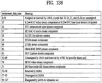
- the atsc:ComponentInfo field may include @atsc:componentType, @atsc:componentRole, @atsc:componentProtectedFlag, @atsc:componentId and/or @atsc:componentName.
- @atsc:componentType is an attribute that indicates the type of this component. Value of 0 indicates an audio component. Value of 1 indicates a video component. Value of 2 indicated a closed caption component. Value of 3 indicates an application component. Values 4 to 7 are reserved. A meaning of a value of this field may be differently set depending on embodiments.
- @atsc:componentRole is an attribute that indicates the role or kind of this component.
- componentRole When componentType attribute above is between 3 to 7, inclusive, the componentRole can be equal to 255. A meaning of a value of this field may be differently set depending on embodiments.
- @atsc:componentProtectedFlag is an attribute that indicates if this component is protected (e.g. encrypted). When this flag is set to a value of 1 this component is protected (e.g. encrypted). When this flag is set to a value of 0 this component is not protected (e.g. encrypted). When not present the value of componentProtectedFlag attribute is inferred to be equal to 0. A meaning of a value of this field may be differently set depending on embodiments.
- @atsc:componentId is an attribute that indicates the identifier of this component.
- the value of this attribute can be the same as the asset_id in the MP table corresponding to this component.
- @atsc:componentName is an attribute that indicates the human readable name of this component.
- the proposed default values may vary depending on embodiments.
- the "use" column illustrated in the figure relates to each field.
- M may denote an essential field
- O may denote an optional field
- OD may denote an optional field having a default value
- CM may denote a conditional essential field.
- 0...1 to 0...N may indicate the number of available fields.
- the Media Presentation Description is an SLS metadata fragment corresponding to a linear service of a given duration defined by the broadcaster (for example a single TV program, or the set of contiguous linear TV programs over a period of time).
- the contents of the MPD provide the resource identifiers for segments and the context for the identified resources within the media presentation.
- the data structure and semantics of the MPD can be according to the MPD defined by MPEG DASH.
- an MPD delivered by an MMTP session describes Representations delivered over broadband, e.g. in the case of a hybrid service, or to support service continuity in handoff from broadcast to broadband due to broadcast signal degradation (e.g. driving under a mountain or through a tunnel).
- MMT signaling messages defined by MMT are delivered by MMTP packets according to signaling message mode defined by MMT.
- the value of the packet_id field of MMTP packets carrying service layer signaling is set to '00' except for MMTP packets carrying MMT signaling messages specific to an asset, which can be set to the same packet_id value as the MMTP packets carrying the asset.
- Identifiers referencing the appropriate package for each service are signaled by the USBD fragment as described above.
- MMT Package Table (MPT) messages with matching MMT_package_id can be delivered on the MMTP session signaled in the SLT.
- Each MMTP session carries MMT signaling messages specific to its session or each asset delivered by the MMTP session.
- USBD of the MMTP session by specifying an IP destination address/port number, etc. of a packet having the SLS for a particular service in the SLT.
- a packet ID of an MMTP packet carrying the SLS may be designated as a particular value such as 00, etc.
- MPT message having a matched packet ID using the above-described package IP information of USBD. As described below, the MPT message may be used to access each service component/asset.
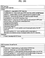
- the following MMTP messages can be delivered by the MMTP session signaled in the SLT.
- MMT Package Table (MPT) message This message carries an MP (MMT Package) table which contains the list of all Assets and their location information as defined by MMT. If an Asset is delivered by a PLP different from the current PLP delivering the MP table, the identifier of the PLP carrying the asset can be provided in the MP table using physical layer pipe identifier descriptor. The physical layer pipe identifier descriptor will be described below.
- MMT ATSC3 (MA3) message mmt_atsc3_message() This message carries system metadata specific for services including service layer signaling as described above. mmt_atsc3_message()will be described below.
- the following MMTP messages can be delivered by the MMTP session signaled in the SLT, if required.
- MPI Media Presentation Information
- Clock Relation Information (CRI) message This message carries a CRI table which contains clock related information for the mapping between the NTP timestamp and the MPEG-2 STC. According to a given embodiment, the CRI message may not be delivered through the MMTP session.
- the following MMTP messages can be delivered by each MMTP session carrying streaming content.
- Hypothetical Receiver Buffer Model message This message carries information required by the receiver to manage its buffer.
- Hypothetical Receiver Buffer Model Removal message This message carries information required by the receiver to manage its MMT de-capsulation buffer.
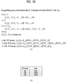
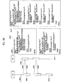
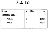
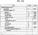
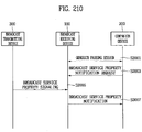
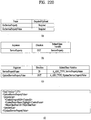
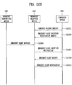
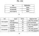
- An MMT Signaling message mmt_atsc3_message() is defined to deliver information specific to services according to the present invention described above.
- the signaling message may include message ID, version, and/or length fields corresponding to basic fields of the MMT signaling message.
- a payload of the signaling message may include service ID information, content type information, content version information, content compression information and/or URI information.
- the content type information may indicate a type of data included in the payload of the signaling message.
- the content version information may indicate a version of data included in the payload, and the content compression information may indicate a type of compression applied to the data.
- the URI information may have URI information related to content delivered by the message.
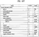
- the physical layer pipe identifier descriptor is a descriptor that can be used as one of descriptors of the MP table described above.
- the physical layer pipe identifier descriptor provides information about the PLP carrying an asset. If an asset is delivered by a PLP different from the current PLP delivering the MP table, the physical layer pipe identifier descriptor can be used as an asset descriptor in the associated MP table to identify the PLP carrying the asset.
- the physical layer pipe identifier descriptor may further include BSID information in addition to PLP ID information.
- the BSID may be an ID of a broadcast stream that delivers an MMTP packet for an asset described by the descriptor.
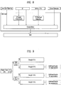
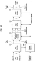
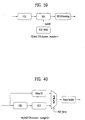
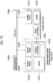
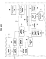
- FIG. 8 illustrates a link layer protocol architecture according to an embodiment of the present invention.
- the link layer is the layer between the physical layer and the network layer, and transports the data from the network layer to the physical layer at the sending side and transports the data from the physical layer to the network layer at the receiving side.
- the purpose of the link layer includes abstracting all input packet types into a single format for processing by the physical layer, ensuring flexibility and future extensibility for as yet undefined input types.
- processing within the link layer ensures that the input data can be transmitted in an efficient manner, for example by providing options to compress redundant information in the headers of input packets.
- the operations of encapsulation, compression and so on are referred to as the link layer protocol and packets created using this protocol are called link layer packets.
- the link layer may perform functions such as packet encapsulation, overhead reduction and/or signaling transmission, etc.
- Link layer protocol allows encapsulation of any type of packet, including ones such as IP packets and MPEG-2 TS.
- the physical layer need only process one single packet format, independent of the network layer protocol type (here we consider MPEG-2 TS packet as a kind of network layer packet.)
- Each network layer packet or input packet is transformed into the payload of a generic link layer packet. Additionally, concatenation and segmentation can be performed in order to use the physical layer resources efficiently when the input packet sizes are particularly small or large.
- segmentation may be used in packet encapsulation.
- the network layer packet is divided into two or more segments.
- the link layer packet header includes protocol fields to perform segmentation on the sending side and reassembly on the receiving side.
- each segment can be encapsulated to link layer packet in the same order as original position in the network layer packet.
- each link layer packet which includes a segment of network layer packet can be transported to PHY layer consequently.
- concatenation may be used in packet encapsulation.
- the link layer packet header includes protocol fields to perform concatenation.
- the concatenation is combining of multiple small sized network layer packets into one payload.
- each network layer packet can be concatenated to payload of link layer packet in the same order as original input order.
- each packet which constructs a payload of link layer packet can be whole packet, not a segment of packet.
- the link layer protocol may provide IP overhead reduction and/or MPEG-2 TS overhead reduction.
- IP overhead reduction IP packets have a fixed header format, however some of the information which is needed in a communication environment may be redundant in a broadcast environment.
- Link layer protocol provides mechanisms to reduce the broadcast overhead by compressing headers of IP packets.
- MPEG-2 TS overhead reduction link layer protocol provides sync byte removal, null packet deletion and/or common header removal (compression).
- sync byte removal provides an overhead reduction of one byte per TS packet
- a null packet deletion mechanism removes the 188 byte null TS packets in a manner that they can be re-inserted at the receiver and finally a common header removal mechanism.
- a particular format for the signaling packet may be provided for link layer signaling, which will be described below.
- link layer protocol takes as input network layer packets such as IPv4, MPEG-2 TS and so on as input packets. Future extension indicates other packet types and protocol which is also possible to be input in link layer.
- Link layer protocol also specifies the format and signaling for any link layer signaling, including information about mapping to specific channel to the physical layer. Figure also shows how ALP incorporates mechanisms to improve the efficiency of transmission, via various header compression and deletion algorithms.
- the link layer protocol may basically encapsulate input packets.
- FIG. 9 illustrates a structure of a base header of a link layer packet according to an embodiment of the present invention.
- the structure of the header will be described.
- a link layer packet can include a header followed by the data payload.
- the header of a link layer packet can include a base header, and may include an additional header depending on the control fields of the base header.
- the presence of an optional header is indicated from flag fields of the additional header.
- a field indicating the presence of an additional header and an optional header may be positioned in the base header.
- the base header for link layer packet encapsulation has a hierarchical structure.
- the base header can be two bytes in length and is the minimum length of the link layer packet header.
- the illustrated base header may include a Packet_Type field, a PC field and/or a length field. According to a given embodiment, the base header may further include an HM field or an S/C field.
- Packet_Type field can be a 3-bit field that indicates the original protocol or packet type of the input data before encapsulation into a link layer packet.
- An IPv4 packet, a compressed IP packet, a link layer signaling packet, and other types of packets may have the base header structure and may be encapsulated.
- the MPEG-2 TS packet may have a different particular structure, and may be encapsulated.
- the value of Packet_Type is "000", "001" "100” or "111"
- that is the original data type of an ALP packet is one of an IPv4 packet, a compressed IP packet, link layer signaling or extension packet.
- the value of Packet_Type can be "010".
- Other values of the Packet_Type field may be reserved for future use.
- Payload_Configuration (PC) field can be a 1-bit field that indicates the configuration of the payload.
- a value of 0 can indicate that the link layer packet carries a single, whole input packet and the following field is the Header_Mode field.
- a value of 1 can indicate that the link layer packet carries more than one input packet (concatenation) or a part of a large input packet (segmentation) and the following field is the Segmentation_Concatenation field.
- Header_Mode (HM) field can be a 1-bit field, when set to 0, that can indicate there is no additional header, and that the length of the payload of the link layer packet is less than 2048 bytes. This value may be varied depending on embodiments. A value of 1 can indicate that an additional header for single packet defined below is present following the Length field. In this case, the length of the payload is larger than 2047 bytes and/or optional features can be used (sub stream identification, header extension, etc.). This value may be varied depending on embodiments. This field can be present only when Payload_Configuration field of the link layer packet has a value of 0.
- Segmentation_Concatenation (S/C) field can be a 1-bit field, when set to 0, that can indicate that the payload carries a segment of an input packet and an additional header for segmentation defined below is present following the Length field.
- a value of 1 can indicate that the payload carries more than one complete input packet and an additional header for concatenation defined below is present following the Length field. This field can be present only when the value of Payload_Configuration field of the ALP packet is 1.
- Length field can be an 11-bit field that indicates the 11 least significant bits (LSBs) of the length in bytes of payload carried by the link layer packet.
- LSBs least significant bits
- the length field is concatenated with the Length_MSB field, and is the LSB to provide the actual total length of the payload.
- the number of bits of the length field may be changed to another value rather than 11 bits.
- a single packet without any additional header a single packet with an additional header
- a segmented packet a concatenated packet.
- more packet configurations may be made through a combination of each additional header, an optional header, an additional header for signaling information to be described below, and an additional header for time extension.
- FIG. 10 illustrates a structure of an additional header of a link layer packet according to an embodiment of the present invention.
- Additional headers may be present. Hereinafter, a description will be given of an additional header for a single packet.
- the Header_Mode (HM) can be set to 1 when the length of the payload of the link layer packet is larger than 2047 bytes or when the optional fields are used.
- the additional header for single packet is shown in Figure (tsib10010).
- Length_MSB field can be a 5-bit field that can indicate the most significant bits (MSBs) of the total payload length in bytes in the current link layer packet, and is concatenated with the Length field containing the 11 least significant bits (LSBs) to obtain the total payload length.
- the maximum length of the payload that can be signaled is therefore 65535 bytes.
- the number of bits of the length field may be changed to another value rather than 11 bits.
- the number of bits of the Length_MSB field may be changed, and thus a maximum expressible payload length may be changed.
- each length field may indicate a length of a whole link layer packet rather than a payload.
- SIF Sub stream Identifier Flag
- SID sub stream ID
- SIF field can be set to 0.
- SIF can be set to 1. The detail of SID is described below.
- HEF Header Extension Flag
- HEF Header Extension Flag
- a value of 0 can indicate that this extension header is not present.
- Segmentation_Concatenation S/C
- Segment_Sequence_Number can be a 5-bit unsigned integer that can indicate the order of the corresponding segment carried by the link layer packet. For the link layer packet which carries the first segment of an input packet, the value of this field can be set to 0x0. This field can be incremented by one with each additional segment belonging to the segmented input packet.
- Last_Segment_Indicator can be a 1-bit field that can indicate, when set to 1, that the segment in this payload is the last one of input packet. A value of 0, can indicate that it is not last segment.
- SIF Sub stream Identifier Flag
- SIF field can be set to 0.
- SIF can be set to 1.
- HEF Header Extension Flag
- HEF Header Extension Flag
- a packet ID field may be additionally provided to indicate that each segment is generated from the same input packet. This field may be unnecessary and thus be omitted when segments are transmitted in order.
- Length_MSB can be a 4-bit field that can indicate MSB bits of the payload length in bytes in this link layer packet.
- the maximum length of the payload is 32767 bytes for concatenation. As described in the foregoing, a specific numeric value may be changed.
- Count can be a field that can indicate the number of the packets included in the link layer packet.
- the number of the packets included in the link layer packet, 2 can be set to this field. So, its maximum value of concatenated packets in a link layer packet is 9.
- a scheme in which the count field indicates the number may be varied depending on embodiments. That is, the numbers from 1 to 8 may be indicated.
- HEF Header Extension Flag
- HEF Header Extension Flag
- Component_Length can be a 12-bit length field that can indicate the length in byte of each packet.
- Component_Length fields are included in the same order as the packets present in the payload except last component packet.
- the number of length field can be indicated by (Count+1).
- length fields the number of which is the same as a value of the count field, may be present.
- a link layer header consists of an odd number of Component_Length
- four stuffing bits can follow after the last Component_Length field. These bits can be set to 0.
- a Component_length field indicating a length of a last concatenated input packet may not be present. In this case, the length of the last concatenated input packet may correspond to a length obtained by subtracting a sum of values indicated by respective Component_length fields from a whole payload length.
- the optional header may be added to a rear of the additional header.
- the optional header field can contain SID and/or header extension.
- the SID is used to filter out specific packet stream in the link layer level.
- One example of SID is the role of service identifier in a link layer stream carrying multiple services.
- the mapping information between a service and the SID value corresponding to the service can be provided in the SLT, if applicable.
- the header extension contains extended field for future use. Receivers can ignore any header extensions which they do not understand.
- SID (Sub stream Identifier) can be an 8-bit field that can indicate the sub stream identifier for the link layer packet. If there is optional header extension, SID present between additional header and optional header extension.
- Header_Extension can include the fields defined below.
- Extension_Type can be an 8-bit field that can indicate the type of the Header_Extension ().
- Extension_Length can be an 8-bit field that can indicate the length of the Header Extension () in bytes counting from the next byte to the last byte of the Header_Extension ().
- Extension_Byte can be a byte representing the value of the Header_Extension ().
- FIG. 11 illustrates a structure of an additional header of a link layer packet according to another embodiment of the present invention.
- Link layer signaling is incorporated into link layer packets are as follows. Signaling packets are identified by when the Packet_Type field of the base header is equal to 100.
- Figure (tsib11010) shows the structure of the link layer packets containing additional header for signaling information.
- the link layer packet can consist of two additional parts, additional header for signaling information and the actual signaling data itself.
- the total length of the link layer signaling packet is shown in the link layer packet header.
- the additional header for signaling information can include following fields. According to a given embodiment, some fields may be omitted.
- Signaling_Type can be an 8-bit field that can indicate the type of signaling.
- Signaling_Type_Extension can be a 16-bit filed that can indicate the attribute of the signaling. Detail of this field can be defined in signaling specification.
- Signaling_Version can be an 8-bit field that can indicate the version of signaling.
- Signaling_Format can be a 2-bit field that can indicate the data format of the signaling data.
- a signaling format may refer to a data format such as a binary format, an XML format, etc.
- Signaling_Encoding can be a 2-bit field that can specify the encoding/compression format. This field may indicate whether compression is not performed and which type of compression is performed.
- Packet type extension can be used when Packet_type is 111 in the base header as described above.
- Figure (tsib11020) shows the structure of the link layer packets containing additional header for type extension.
- the additional header for type extension can include following fields. According to a given embodiment, some fields may be omitted.
- extended_type can be a 16-bit field that can indicate the protocol or packet type of the input encapsulated in the link layer packet as payload. This field cannot be used for any protocol or packet type already defined by Packet_Type field.
- FIG. 12 illustrates a header structure of a link layer packet for an MPEG-2 TS packet and an encapsulation process thereof according to an embodiment of the present invention.
- the Packet_Type field of the base header is equal to 010.
- Multiple TS packets can be encapsulated within each link layer packet.
- the number of TS packets is signaled via the NUMTS field.
- a particular link layer packet header format may be used.
- Link layer provides overhead reduction mechanisms for MPEG-2 TS to enhance the transmission efficiency.
- the sync byte (0x47) of each TS packet can be deleted.
- the option to delete NULL packets and similar TS headers is also provided.
- Deleted null packets can be recovered in receiver side using DNP field.
- the DNP field indicates the count of deleted null packets. Null packet deletion mechanism using DNP field is described below.
- Similar header of MPEG-2 TS packets can be removed.
- the header is sent once at the first packet and the other headers are deleted.
- HDM field can indicate whether the header deletion is performed or not. Detailed procedure of common TS header deletion is described below.
- overhead reduction can be performed in sequence of sync removal, null packet deletion, and common header deletion. According to a given embodiment, a performance order of respective mechanisms may be changed. In addition, some mechanisms may be omitted according to a given embodiment.
- Packet_Type can be a 3-bit field that can indicate the protocol type of input packet as describe above. For MPEG-2 TS packet encapsulation, this field can always be set to 010.
- NUMTS Number of TS packets
- NUMTS Number of TS packets
- a maximum of 16 TS packets can be supported in one link layer packet.
- NUMTS 0001 means one TS packet is carried.
- AHF Additional Header Flag
- AHF Additional Header Flag
- a value of 0 indicates that there is no additional header.
- a value of 1 indicates that an additional header of length 1-byte is present following the base header. If null TS packets are deleted or TS header compression is applied this field can be set to 1.
- the additional header for TS packet encapsulation consists of the following two fields and is present only when the value of AHF in this link layer packet is set to 1.
- HDM Header Deletion Mode
- HDM Header Deletion Mode
- a value of 1 indicates that TS header deletion can be applied.
- a value of "0" indicates that the TS header deletion method is not applied to this link layer packet.
- DNP Deleted Null Packets
- DNP can be a 7-bit field that indicates the number of deleted null TS packets prior to this link layer packet. A maximum of 128 null TS packets can be deleted.
- the number of bits of each field described above may be changed. According to the changed number of bits, a minimum/maximum value of a value indicated by the field may be changed. These numbers may be changed by a designer.
- the SYNC byte (0x47) from the start of each TS packet can be deleted.
- the length of the MPEG2-TS packet encapsulated in the payload of the link layer packet is always of length 187 bytes (instead of 188 bytes originally).
- Transport Stream rules require that bit rates at the output of a transmitter's multiplexer and at the input of the receiver's de-multiplexer are constant in time and the end-to-end delay is also constant.
- null packets may be present in order to accommodate variable bitrate services in a constant bitrate stream.
- TS null packets may be removed. The process is carried-out in a way that the removed null packets can be re-inserted in the receiver in the exact place where they were originally, thus guaranteeing constant bitrate and avoiding the need for PCR time stamp updating.
- a counter called DNP Deleted Null-Packets
- DNP Deleted Null-Packets
- a counter called DNP can first be reset to zero and then incremented for each deleted null packet preceding the first non-null TS packet to be encapsulated into the payload of the current link layer packet. Then a group of consecutive useful TS packets is encapsulated into the payload of the current link layer packet and the value of each field in its header can be determined. After the generated link layer packet is injected to the physical layer, the DNP is reset to zero. When DNP reaches its maximum allowed value, if the next packet is also a null packet, this null packet is kept as a useful packet and encapsulated into the payload of the next link layer packet.
- Each link layer packet can contain at least one useful TS packet in its payload.
- TS packet header deletion may be referred to as TS packet header compression.
- the header is sent once at the first packet and the other headers are deleted.
- header deletion cannot be applied in transmitter side.
- HDM field can indicate whether the header deletion is performed or not.
- TS header deletion is performed, HDM can be set to 1.
- the deleted packet headers are recovered, and the continuity counter is restored by increasing it in order from that of the first header.
- An example tsib12020 illustrated in the figure is an example of a process in which an input stream of a TS packet is encapsulated into a link layer packet.
- a TS stream including TS packets having SYNC byte (0x47) may be input.
- sync bytes may be deleted through a sync byte deletion process. In this example, it is presumed that null packet deletion is not performed.
- packet headers of eight TS packets have the same field values except for CC, that is, a continuity counter field value.
- the processed TS packets may be encapsulated into a payload of the link layer packet.
- a Packet_Type field corresponds to a case in which TS packets are input, and thus may have a value of 010.
- a NUMTS field may indicate the number of encapsulated TS packets.
- An AHF field may be set to 1 to indicate the presence of an additional header since packet header deletion is performed.
- An HDM field may be set to 1 since header deletion is performed.
- DNP may be set to 0 since null packet deletion is not performed.
- FIG. 13 illustrates an example of adaptation modes in IP header compression according to an embodiment of the present invention (transmitting side).
- IP header compression will be described.
- IP header compression/decompression scheme can be provided.
- IP header compression can include two parts: header compressor/decompressor and adaptation module.
- the header compression scheme can be based on the Robust Header Compression (RoHC).
- RoHC Robust Header Compression
- adaptation function is added for broadcasting usage.
- ROHC compressor reduces the size of header for each packet. Then, adaptation module extracts context information and builds signaling information from each packet stream. In the receiver side, adaptation module parses the signaling information associated with the received packet stream and attaches context information to the received packet stream. ROHC decompressor reconstructs the original IP packet by recovering the packet header.
- the header compression scheme can be based on the RoHC as described above.
- an RoHC framework can operate in a unidirctional mode (U mode) of the RoHC.
- U mode unidirctional mode
- the Adaptation function provides out-of-band transmission of the configuration parameters and context information. Out-of-band transmission can be done through the link layer signaling. Therefore, the adaptation function is used to reduce the channel change delay and decompression error due to loss of context information.
- Context information may be extracted using various schemes according to adaptation mode. In the present invention, three examples will be described below. The scope of the present invention is not restricted to the examples of the adaptation mode to be described below.
- the adaptation mode may be referred to as a context extraction mode.
- Adaptation Mode 1 may be a mode in which no additional operation is applied to a basic RoHC packet stream.
- the adaptation module may operate as a buffer in this mode. Therefore, in this mode, context information may not be included in link layer signaling
- the adaptation module can detect the IR packet from ROHC packet flow and extract the context information (static chain). After extracting the context information, each IR packet can be converted to an IR-DYN packet. The converted IR-DYN packet can be included and transmitted inside the ROHC packet flow in the same order as IR packet, replacing the original packet.
- the adaptation module can detect the IR and IR-DYN packet from ROHC packet flow and extract the context information.
- the static chain and dynamic chain can be extracted from IR packet and dynamic chain can be extracted from IR-DYN packet.
- each IR and IR-DYN packet can be converted to a compressed packet.
- the compressed packet format can be the same with the next packet of IR or IR-DYN packet.
- the converted compressed packet can be included and transmitted inside the ROHC packet flow in the same order as IR or IR-DYN packet, replacing the original packet.
- context information can be encapsulated based on transmission structure.
- context information can be encapsulated to the link layer signaling.
- the packet type value can be set to "100".
- a link layer packet for context information may have a packet type field value of 100.
- a link layer packet for compressed IP packets may have a packet type field value of 001. The values indicate that each of the signaling information and the compressed IP packets are included in the link layer packet as described above.
- the extracted context information can be transmitted separately from ROHC packet flow, with signaling data through specific physical data path.
- the transmission of context depends on the configuration of the physical layer path.
- the context information can be sent with other link layer signaling through the signaling data pipe.
- the signaling PLP may refer to an L1 signaling path.
- the signaling PLP may not be separated from the general PLP, and may refer to a particular and general PLP through which the signaling information is transmitted.
- a receiver may need to acquire signaling information.
- the context signaling can be also received.
- the PLP to receive packet stream can be selected.
- the receiver may acquire the signaling information including the context information by selecting the initial PLP.
- the initial PLP may be the above-described signaling PLP.
- the receiver may select a PLP for acquiring a packet stream. In this way, the context information may be acquired prior to reception of the packet stream.
- the adaptation module can detect IR-DYN packet form received packet flow. Then, the adaptation module parses the static chain from the context information in the signaling data. This is similar to receiving the IR packet. For the same context identifier, IR-DYN packet can be recovered to IR packet. Recovered ROHC packet flow can be sent to ROHC decompressor. Thereafter, decompression may be started.
- FIG. 14 illustrates a link mapping table (LMT) and an RoHC-U description table according to an embodiment of the present invention.
- link layer signaling is operates under IP level.
- link layer signaling can be obtained earlier than IP level signaling such as Service List Table (SLT) and Service Layer Signaling (SLS). Therefore, link layer signaling can be obtained before session establishment.
- SLT Service List Table
- SLS Service Layer Signaling
- link layer signaling there can be two kinds of signaling according input path: internal link layer signaling and external link layer signaling.
- the internal link layer signaling is generated in link layer at transmitter side.
- the link layer takes the signaling from external module or protocol. This kind of signaling information is considered as external link layer signaling. If some signaling need to be obtained prior to IP level signaling, external signaling is transmitted in format of link layer packet.
- the link layer signaling can be encapsulated into link layer packet as described above.
- the link layer packets can carry any format of link layer signaling, including binary and XML.
- the same signaling information may not be transmitted in different formats for the link layer signaling.
- Internal link layer signaling may include signaling information for link mapping.
- the Link Mapping Table (LMT) provides a list of upper layer sessions carried in a PLP.
- the LMT also provides addition information for processing the link layer packets carrying the upper layer sessions in the link layer.
- signaling_type can be an 8-bit unsigned integer field that indicates the type of signaling carried by this table.
- the value of signaling_type field for Link Mapping Table (LMT) can be set to 0x01.
- PLP_ID can be an 8-bit field that indicates the PLP corresponding to this table.
- num_session can be an 8-bit unsigned integer field that provides the number of upper layer sessions carried in the PLP identified by the above PLP_ID field.
- signaling_type field When the value of signaling_type field is 0x01, this field can indicate the number of UDP/IP sessions in the PLP.
- src_IP_add can be a 32-bit unsigned integer field that contains the source IP address of an upper layer session carried in the PLP identified by the PLP_ID field.
- dst_IP_add can be a 32-bit unsigned integer field that contains the destination IP address of an upper layer session carried in the PLP identified by the PLP_ID field.
- src_UDP_port can be a 16-bit unsigned integer field that represents the source UDP port number of an upper layer session carried in the PLP identified by the PLP_ID field.
- dst_UDP_port can be a 16-bit unsigned integer field that represents the destination UDP port number of an upper layer session carried in the PLP identified by the PLP_ID field.
- SID_flag can be a 1-bit Boolean field that indicates whether the link layer packet carrying the upper layer session identified by above 4 fields, Src_IP_add, Dst_IP_add, Src_UDP_Port and Dst_UDP_Port, has an SID field in its optional header. When the value of this field is set to 0, the link layer packet carrying the upper layer session may not have an SID field in its optional header. When the value of this field is set to 1, the link layer packet carrying the upper layer session can have an SID field in its optional header and the value the SID field can be same as the following SID field in this table.
- compressed_flag can be a 1-bit Boolean field that indicates whether the header compression is applied the link layer packets carrying the upper layer session identified by above 4 fields, Src_IP_add, Dst_IP_add, Src_UDP_Port and Dst_UDP_Port.
- the link layer packet carrying the upper layer session may have a value of 0x00 of Packet_Type field in its base header.
- the link layer packet carrying the upper layer session may have a value of 0x01 of Packet_Type field in its base header and the Context_ID field can be present.
- SID can be an 8-bit unsigned integer field that indicates sub stream identifier for the link layer packets carrying the upper layer session identified by above 4 fields, Src_IP_add, Dst_IP_add, Src_UDP_Port and Dst_UDP_Port. This field can be present when the value of SID_flag is equal to 1.
- context_id can be an 8-bit field that provides a reference for the context id (CID) provided in the ROHC-U description table. This field can be present when the value of compressed_flag is equal to 1.
- the RoHC-U adaptation module may generate information related to header compression.
- signaling_type can be an 8-bit field that indicates the type of signaling carried by this table.
- the value of signaling_type field for ROHC-U description table (RDT) can be set to "0x02".
- PLP_ID can be an 8-bit field that indicates the PLP corresponding to this table.
- context_id can be an 8-bit field that indicates the context id (CID) of the compressed IP stream.
- CID context id
- context_profile can be an 8-bit field that indicates the range of protocols used to compress the stream. This field can be omitted.
- adaptation_mode can be a 2-bit field that indicates the mode of adaptation module in this PLP. Adaptation modes have been described above.
- context_config can be a 2-bit field that indicates the combination of the context information. If there is no context information in this table, this field may be set to "0x0". If the static_chain() or dynamic_chain() byte is included in this table, this field may be set to "0x01" or "0x02" respectively. If both of the static_chain() and dynamic_chain() byte are included in this table, this field may be set to "0x03".
- context_length can be an 8-bit field that indicates the length of the static chain byte sequence. This field can be omitted.
- static_chain_byte can be a field that conveys the static information used to initialize the ROHC-U decompressor. The size and structure of this field depend on the context profile.
- dynamic_chain_byte can be a field that conveys the dynamic information used to initialize the ROHC-U decompressor.
- the size and structure of this field depend on the context profile.
- the static_chain_byte can be defined as sub-header information of IR packet.
- the dynamic_chain_byte can be defined as sub-header information of IR packet and IR-DYN packet.
- FIG. 15 illustrates a structure of a link layer on a transmitter side according to an embodiment of the present invention.
- the link layer on the transmitter side may broadly include a link layer signaling part in which signaling information is processed, an overhead reduction part, and/or an encapsulation part.
- the link layer on the transmitter side may include a scheduler for controlling and scheduling an overall operation of the link layer and/or input and output parts of the link layer.
- signaling information of an upper layer and/or a system parameter tsib15010 may be delivered to the link layer.
- an IP stream including IP packets may be delivered to the link layer from an IP layer tsib15110.
- the scheduler tsib15020 may determine and control operations of several modules included in the link layer.
- the delivered signaling information and/or system parameter tsib15010 may be filterer or used by the scheduler tsib15020.
- Information, which corresponds to a part of the delivered signaling information and/or system parameter tsib15010, necessary for a receiver may be delivered to the link layer signaling part.
- information, which corresponds to a part of the signaling information, necessary for an operation of the link layer may be delivered to an overhead reduction controller tsib15120 or an encapsulation controller tsib15180.
- the link layer signaling part may collect information to be transmitted as a signal in a physical layer, and convert/configure the information in a form suitable for transmission.
- the link layer signaling part may include a signaling manager tsib15030, a signaling formatter tsib15040, and/or a buffer for channels tsib15050.
- the signaling manager tsib15030 may receive signaling information delivered from the scheduler tsib15020 and/or signaling (and/or context) information delivered from the overhead reduction part.
- the signaling manager tsib15030 may determine a path for transmission of the signaling information for delivered data.
- the signaling information may be delivered through the path determined by the signaling manager tsib15030.
- signaling information to be transmitted through a divided channel such as the FIC, the EAS, etc. may be delivered to the signaling formatter tsib15040, and other signaling information may be delivered to an encapsulation buffer tsib15070.
- the signaling formatter tsib15040 may format related signaling information in a form suitable for each divided channel such that signaling information may be transmitted through a separately divided channel.
- the physical layer may include separate physically/logically divided channels.
- the divided channels may be used to transmit FIC signaling information or EAS-related information.
- the FIC or EAS-related information may be sorted by the signaling manager tsib15030, and input to the signaling formatter tsib15040.
- the signaling formatter tsib15040 may format the information based on each separate channel.
- a signaling formatter for the particular signaling information may be additionally provided. Through this scheme, the link layer may be compatible with various physical layers.
- the buffer for channels tsib15050 may deliver the signaling information received from the signaling formatter tsib15040 to separate dedicated channels tsib15060.
- the number and content of the separate channels may vary depending on embodiments.
- the signaling manager tsib15030 may deliver signaling information, which is not delivered to a particular channel, to the encapsulation buffer tsib15070.
- the encapsulation buffer tsib15070 may function as a buffer that receives the signaling information which is not delivered to the particular channel.
- An encapsulation block for signaling information tsib15080 may encapsulate the signaling information which is not delivered to the particular channel.
- a transmission buffer tsib15090 may function as a buffer that delivers the encapsulated signaling information to a DP for signaling information tsib15100.
- the DP for signaling information tsib15100 may refer to the above-described PLS region.
- the overhead reduction part may allow efficient transmission by removing overhead of packets delivered to the link layer. It is possible to configure overhead reduction parts corresponding to the number of IP streams input to the link layer.
- An overhead reduction buffer tsi15130 may receive an IP packet delivered from an upper layer. The received IP packet may be input to the overhead reduction part through the overhead reduction buffer tsib15130.
- An overhead reduction controller tsib15120 may determine whether to perform overhead reduction on a packet stream input to the overhead reduction buffer tsib15130.
- the overhead reduction controller tsib15120 may determine whether to perform overhead reduction for each packet stream.
- packets When overhead reduction is performed on a packet stream, packets may be delivered to a robust header compression (RoHC) compressor tsib15140 to perform overhead reduction.
- RoHC header compression
- packets When overhead reduction is not performed on a packet stream, packets may be delivered to the encapsulation part to perform encapsulation without overhead reduction.
- Whether to perform overhead reduction of packets may be determined based on the signaling information tsib15010 delivered to the link layer. The signaling information may be delivered to the encapsulation controller tsib15180 by the scheduler tsib15020.
- the RoHC compressor tsib15140 may perform overhead reduction on a packet stream.
- the RoHC compressor tsib15140 may perform an operation of compressing a header of a packet.
- Various schemes may be used for overhead reduction. Overhead reduction may be performed using a scheme proposed by the present invention.
- the present invention presumes an IP stream, and thus an expression "RoHC compressor" is used. However, the name may be changed depending on embodiments.
- the operation is not restricted to compression of the IP stream, and overhead reduction of all types of packets may be performed by the RoHC compressor tsib15140.
- a packet stream configuration block tsib15150 may separate information to be transmitted to a signaling region and information to be transmitted to a packet stream from IP packets having compressed headers.
- the information to be transmitted to the packet stream may refer to information to be transmitted to a DP region.
- the information to be transmitted to the signaling region may be delivered to a signaling and/or context controller tsib15160.
- the information to be transmitted to the packet stream may be transmitted to the encapsulation part.
- the signaling and/or context controller tsib15160 may collect signaling and/or context information and deliver the signaling and/or context information to the signaling manager in order to transmit the signaling and/or context information to the signaling region.
- the encapsulation part may perform an operation of encapsulating packets in a form suitable for a delivery to the physical layer. It is possible to configure encapsulation parts corresponding to the number of IP streams.
- An encapsulation buffer tsib15170 may receive a packet stream for encapsulation. Packets subjected to overhead reduction may be received when overhead reduction is performed, and an input IP packet may be received without change when overhead reduction is not performed.
- An encapsulation controller tsib15180 may determine whether to encapsulate an input packet stream. When encapsulation is performed, the packet stream may be delivered to a segmentation/concatenation block tsib15190. When encapsulation is not performed, the packet stream may be delivered to a transmission buffer tsib15230. Whether to encapsulate packets may be determined based on the signaling information tsib15010 delivered to the link layer. The signaling information may be delivered to the encapsulation controller tsib15180 by the scheduler tsib15020.
- the above-described segmentation or concatenation operation may be performed on packets.
- one IP packet may be segmented into several segments to configure a plurality of link layer packet payloads.
- several IP packets may be concatenated to configure one link layer packet payload.
- a packet configuration table tsib15200 may have configuration information of a segmented and/or concatenated link layer packet.
- a transmitter and a receiver may have the same information in the packet configuration table tsib15200.
- the transmitter and the receiver may refer to the information of the packet configuration table tsib15200.
- An index value of the information of the packet configuration table tsib15200 may be included in a header of the link layer packet.
- a link layer header information block tsib15210 may collect header information generated in an encapsulation process.
- the link layer header information block tsib15210 may collect header information included in the packet configuration table tsib15200.
- the link layer header information block tsib15210 may configure header information according to a header structure of the link layer packet.
- a header attachment block tsib15220 may add a header to a payload of a segmented and/or concatenated link layer packet.
- the transmission buffer tsib15230 may function as a buffer to deliver the link layer packet to a DP tsib15240 of the physical layer.
- the respective blocks, modules, or parts may be configured as one module/protocol or a plurality of modules/protocols in the link layer.
- FIG. 16 illustrates a structure of a link layer on a receiver side according to an embodiment of the present invention.
- the link layer on the receiver side may broadly include a link layer signaling part in which signaling information is processed, an overhead processing part, and/or a decapsulation part.
- the link layer on the receiver side may include a scheduler for controlling and scheduling overall operation of the link layer and/or input and output parts of the link layer.
- information received through a physical layer may be delivered to the link layer.
- the link layer may process the information, restore an original state before being processed at a transmitter side, and then deliver the information to an upper layer.
- the upper layer may be an IP layer.
- the link layer signaling part may determine signaling information received from the physical layer, and deliver the determined signaling information to each part of the link layer.
- a buffer for channels tsib16040 may function as a buffer that receives signaling information transmitted through particular channels. As described in the foregoing, when physically/logically divided separate channels are present in the physical layer, it is possible to receive signaling information transmitted through the channels. When the information received from the separate channels is segmented, the segmented information may be stored until complete information is configured.
- a signaling decoder/parser tsib16050 may verify a format of the signaling information received through the particular channel, and extract information to be used in the link layer.
- decoding may be performed.
- a signaling manager tsib16060 may integrate signaling information received through several paths. Signaling information received through a DP for signaling tsib16070 to be described below may be integrated in the signaling manager tsib16060.
- the signaling manager tsib16060 may deliver signaling information necessary for each part in the link layer. For example, the signaling manager tsib16060 may deliver context information, etc. for recovery of a packet to the overhead processing part. In addition, the signaling manager tsib16060 may deliver signaling information for control to a scheduler tsib16020.
- General signaling information which is not received through a separate particular channel, may be received through the DP for signaling tsib16070.
- the DP for signaling may refer to PLS, L1, etc.
- the DP may be referred to as a PLP.
- a reception buffer tsib16080 may function as a buffer that receives signaling information delivered from the DP for signaling.
- the received signaling information may be decapsulated.
- the decapsulated signaling information may be delivered to the signaling manager tsib16060 through a decapsulation buffer tsib16100.
- the signaling manager tsib16060 may collate signaling information, and deliver the collated signaling information to a necessary part in the link layer.
- the scheduler tsib16020 may determine and control operations of several modules included in the link layer.
- the scheduler tsib16020 may control each part of the link layer using receiver information tsib16010 and/or information delivered from the signaling manager tsib16060.
- the scheduler tsib16020 may determine an operation mode, etc. of each part.
- the receiver information tsib16010 may refer to information previously stored in the receiver.
- the scheduler tsib16020 may use information changed by a user such as channel switching, etc. to perform a control operation.
- the decapsulation part may filter a packet received from a DP tsib16110 of the physical layer, and separate a packet according to a type of the packet. It is possible to configure decapsulation parts corresponding to the number of DPs that can be simultaneously decoded in the physical layer.
- the decapsulation buffer tsib16100 may function as a buffer that receives a packet stream from the physical layer to perform decapsulation.
- a decapsulation controller tsib16130 may determine whether to decapsulate an input packet stream. When decapsulation is performed, the packet stream may be delivered to a link layer header parser tsib16140. When decapsulation is not performed, the packet stream may be delivered to an output buffer tsib16220.
- the signaling information received from the scheduler tsib16020 may be used to determine whether to perform decapsulation.
- the link layer header parser tsib16140 may identify a header of the delivered link layer packet. It is possible to identify a configuration of an IP packet included in a payload of the link layer packet by identifying the header. For example, the IP packet may be segmented or concatenated.
- a packet configuration table tsib16150 may include payload information of segmented and/or concatenated link layer packets.
- the transmitter and the receiver may have the same information in the packet configuration table tsib16150.
- the transmitter and the receiver may refer to the information of the packet configuration table tsib16150. It is possible to find a value necessary for reassembly based on index information included in the link layer packet.
- a reassembly block tsib16160 may configure payloads of the segmented and/or concatenated link layer packets as packets of an original IP stream. Segments may be collected and reconfigured as one IP packet, or concatenated packets may be separated and reconfigured as a plurality of IP packet streams. Recombined IP packets may be delivered to the overhead processing part.
- the overhead processing part may perform an operation of restoring a packet subjected to overhead reduction to an original packet as a reverse operation of overhead reduction performed in the transmitter. This operation may be referred to as overhead processing. It is possible to configure overhead processing parts corresponding to the number of DPs that can be simultaneously decoded in the physical layer.
- a packet recovery buffer tsib16170 may function as a buffer that receives a decapsulated RoHC packet or IP packet to perform overhead processing.
- An overhead controller tsib16180 may determine whether to recover and/or decompress the decapsulated packet. When recovery and/or decompression are performed, the packet may be delivered to a packet stream recovery block tsib16190. When recovery and/or decompression are not performed, the packet may be delivered to the output buffer tsib16220. Whether to perform recovery and/or decompression may be determined based on the signaling information delivered by the scheduler tsib16020.
- the packet stream recovery block tsib16190 may perform an operation of integrating a packet stream separated from the transmitter with context information of the packet stream. This operation may be a process of restoring a packet stream such that an RoHC decompressor tsib16210 can perform processing. In this process, it is possible to receive signaling information and/or context information from a signaling and/or context controller tsib16200.
- the signaling and/or context controller tsib16200 may determine signaling information delivered from the transmitter, and deliver the signaling information to the packet stream recovery block tsib16190 such that the signaling information may be mapped to a stream corresponding to a context ID.
- the RoHC decompressor tsib16210 may restore headers of packets of the packet stream.
- the packets of the packet stream may be restored to forms of original IP packets through restoration of the headers.
- the RoHC decompressor tsib16210 may perform overhead processing.
- the output buffer tsib16220 may function as a buffer before an output stream is delivered to an IP layer tsib16230.
- the link layers of the transmitter and the receiver proposed in the present invention may include the blocks or modules described above.
- the link layer may independently operate irrespective of an upper layer and a lower layer, overhead reduction may be efficiently performed, and a supportable function according to an upper/lower layer may be easily defined/added/deleted.
- FIG. 17 illustrates a configuration of signaling transmission through a link layer according to an embodiment of the present invention (transmitting/receiving sides).
- a plurality of service providers may provide services within one frequency band.
- a service provider may provide a plurality of services, and one service may include one or more components. It can be considered that the user receives content using a service as a unit.
- the present invention presumes that a transmission protocol based on a plurality of sessions is used to support an IP hybrid broadcast. Signaling information delivered through a signaling path may be determined based on a transmission configuration of each protocol. Various names may be applied to respective protocols according to a given embodiment.
- service providers may provide a plurality of services (Service #1, #2, ).
- Service #1, #2, a signal for a service may be transmitted through a general transport session (signaling C).
- the signal may be transmitted through a particular session (dedicated session) according to a given embodiment (signaling B).
- Service data and service signaling information may be encapsulated according to a transmission protocol.
- an IP/UDP layer may be used.
- a signal in the IP/UDP layer (signaling A) may be additionally provided. This signaling may be omitted.
- Data processed using the IP/UDP may be input to the link layer.
- overhead reduction and/or encapsulation may be performed in the link layer.
- link layer signaling may be additionally provided.
- Link layer signaling may include a system parameter, etc. Link layer signaling has been described above.
- the service data and the signaling information subjected to the above process may be processed through PLPs in a physical layer.
- a PLP may be referred to as a DP.
- the example illustrated in the figure presumes a case in which a base DP/PLP is used. However, depending on embodiments, transmission may be performed using only a general DP/PLP without the base DP/PLP.
- a particular channel such as an FIC, an EAC, etc.
- a signal delivered through the FIC may be referred to as a fast information table (FIT)
- a signal delivered through the EAC may be referred to as an emergency alert table (EAT).
- the FIT may be identical to the above-described SLT.
- the particular channels may not be used depending on embodiments.
- the FIT and the EAT may be transmitted using a general link layer signaling transmission scheme, or transmitted using a PLP via the IP/UDP as other service data.
- system parameters may include a transmitter-related parameter, a service provider-related parameter, etc.
- Link layer signaling may include IP header compression-related context information and/or identification information of data to which the context is applied.
- Signaling of an upper layer may include an IP address, a UDP number, service/component information, emergency alert-related information, an IP/UDP address for service signaling, a session ID, etc. Detailed examples thereof have been described above.
- the receiver may decode only a PLP for a corresponding service using signaling information without having to decode all PLPs.
- the receiver when the user selects or changes a service desired to be received, the receiver may be tuned to a corresponding frequency and may read receiver information related to a corresponding channel stored in a DB, etc.
- the information stored in the DB, etc. of the receiver may be configured by reading an SLT at the time of initial channel scan.
- information previously stored in the DB is updated, and information about a transmission path of the service selected by the user and information about a path, through which component information is acquired or a signal necessary to acquire the information is transmitted, are acquired.
- decoding or parsing may be omitted.
- the receiver may verify whether SLT information is included in a PLP by parsing physical signaling of the PLP in a corresponding broadcast stream (not illustrated), which may be indicated through a particular field of physical signaling. It is possible to access a position at which a service layer signal of a particular service is transmitted by accessing the SLT information.
- the service layer signal may be encapsulated into the IP/UDP and delivered through a transport session. It is possible to acquire information about a component included in the service using this service layer signaling.
- a specific SLT-SLS configuration is as described above.
- the transmission path information may include an IP address, a UDP port number, a session ID, a PLP ID, etc.
- a value previously designated by the IANA or a system may be used as an IP/UDP address.
- the information may be acquired using a scheme of accessing a DB or a shared memory, etc.
- service data delivered through the PLP may be temporarily stored in a device such as a buffer, etc. while the link layer signal is decoded.
- a received packet stream may be subjected to decapsulation and header recovery using information such as overhead reduction for a PLP to be received, etc.
- the FIC and the EAC are used, and a concept of the base DP/PLP is presumed. As described in the foregoing, concepts of the FIC, the EAC, and the base DP/PLP may not be used.
- the present invention is applicable to systems using two or more antennas.
- the present invention proposes a physical profile (or system) optimized to minimize receiver complexity while attaining the performance required for a particular use case.
- Physical (PHY) profiles base, handheld and advanced profiles
- PHY profiles are subsets of all configurations that a corresponding receiver should implement.
- the PHY profiles share most of the functional blocks but differ slightly in specific blocks and/or parameters.
- future profiles may also be multiplexed with existing profiles in a single radio frequency (RF) channel through a future extension frame (FEF).
- RF radio frequency
- FEF future extension frame
- the base profile and the handheld profile according to the embodiment of the present invention refer to profiles to which MIMO is not applied, and the advanced profile refers to a profile to which MIMO is applied.
- the base profile may be used as a profile for both the terrestrial broadcast service and the mobile broadcast service. That is, the base profile may be used to define a concept of a profile which includes the mobile profile.
- the advanced profile may be divided into an advanced profile for a base profile with MIMO and an advanced profile for a handheld profile with MIMO.
- the profiles may be changed according to intention of the designer,
- Auxiliary stream sequence of cells carrying data of as yet undefined modulation and coding, which may be used for future extensions or as required by broadcasters or network operators
- Base data pipe data pipe that carries service signaling data
- Baseband frame (or BBFRAME): set of Kbch bits which form the input to one FEC encoding process (BCH and LDPC encoding)
- the preamble symbol is mainly used for fast initial band scan to detect the system signal, timing thereof, frequency offset, and FFT size.
- FIG. 18 illustrates a configuration of a broadcast signal transmission apparatus for future broadcast services according to an embodiment of the present invention.
- the broadcast signal transmission apparatus for future broadcast services may include an input formatting block 1000, a bit interleaved coding & modulation (BICM) block 1010, a frame building block 1020, an OFDM generation block 1030 and a signaling generation block 1040. Description will be given of an operation of each block of the broadcast signal transmission apparatus.
- BICM bit interleaved coding & modulation
- IP stream/packets and MPEG2-TS may be main input formats, and other stream types are handled as general streams.
- management information is input to control scheduling and allocation of the corresponding bandwidth for each input stream.
- the present invention allows simultaneous input of one or a plurality of TS streams, IP stream(s) and/or a general stream(s).
- the input formatting block 1000 may demultiplex each input stream into one or a plurality of data pipes, to each of which independent coding and modulation are applied.
- a DP is the basic unit for robustness control, which affects QoS.
- One or a plurality of services or service components may be carried by one DP.
- the DP is a logical channel in a physical layer for delivering service data or related metadata capable of carrying one or a plurality of services or service components.
- a DPU is a basic unit for allocating data cells to a DP in one frame.
- An input to the physical layer may include one or a plurality of data streams. Each of the data streams is delivered by one DP.
- the input formatting block 1000 may covert a data stream input through one or more physical paths (or DPs) into a baseband frame (BBF). In this case, the input formatting block 1000 may perform null packet deletion or header compression on input data (a TS or IP input stream) in order to enhance transmission efficiency.
- a receiver may have a priori information for a particular part of a header, and thus this known information may be deleted from a transmitter.
- a null packet deletion block 3030 may be used only for a TS input stream.
- parity data is added for error correction and encoded bit streams are mapped to complex-value constellation symbols.
- the symbols are interleaved across a specific interleaving depth that is used for the corresponding DP.
- MIMO encoding is performed in the BICM block 1010 and an additional data path is added at the output for MIMO transmission.
- the frame building block 1020 may map the data cells of the input DPs into the OFDM symbols within a frame, and perform frequency interleaving for frequency-domain diversity, especially to combat frequency-selective fading channels.
- the frame building block 1020 may include a delay compensation block, a cell mapper and a frequency interleaver.
- the delay compensation block may adjust timing between DPs and corresponding PLS data to ensure that the DPs and the corresponding PLS data are co-timed at a transmitter side.
- the PLS data is delayed by the same amount as the data pipes by addressing the delays of data pipes caused by the input formatting block and BICM block.
- the delay of the BICM block is mainly due to the time interleaver.
- In-band signaling data carries information of the next TI group so that the information is carried one frame ahead of the DPs to be signaled.
- the delay compensation block delays in-band signaling data accordingly.
- the cell mapper may map PLS, DPs, auxiliary streams, dummy cells, etc. to active carriers of the OFDM symbols in the frame.
- the basic function of the cell mapper 7010 is to map data cells produced by the TIs for each of the DPs, PLS cells, and EAC/FIC cells, if any, into arrays of active OFDM cells corresponding to each of the OFDM symbols within a frame.
- a basic function of the cell mapper is to map a data cell generated by time interleaving for each DP and PLS cell to an array of active OFDM cells (if present) corresponding to respective OFDM symbols in one frame.
- Service signaling data (such as program specific information (PSI)/SI) may be separately gathered and sent by a DP.
- the cell mapper operates according to dynamic information produced by a scheduler and the configuration of a frame structure.
- the frequency interleaver may randomly interleave data cells received from the cell mapper to provide frequency diversity.
- the frequency interleaver may operate on an OFDM symbol pair including two sequential OFDM symbols using a different interleaving-seed order to obtain maximum interleaving gain in a single frame.
- the OFDM generation block 1030 modulates OFDM carriers by cells produced by the frame building block, inserts pilots, and produces a time domain signal for transmission. In addition, this block subsequently inserts guard intervals, and applies peak-to-average power ratio (PAPR) reduction processing to produce a final RF signal.
- PAPR peak-to-average power ratio
- the OFDM generation block 1030 may apply conventional OFDM modulation having a cyclic prefix as a guard interval.
- a distributed MISO scheme is applied across transmitters.
- a PAPR scheme is performed in the time domain.
- the present invention provides a set of various FFT sizes, guard interval lengths and corresponding pilot patterns.
- the present invention may multiplex signals of a plurality of broadcast transmission/reception systems in the time domain such that data of two or more different broadcast transmission/reception systems providing broadcast services may be simultaneously transmitted in the same RF signal bandwidth.
- the two or more different broadcast transmission/reception systems refer to systems providing different broadcast services.
- the different broadcast services may refer to a terrestrial broadcast service, mobile broadcast service, etc.
- the signaling generation block 1040 may create physical layer signaling information used for an operation of each functional block. This signaling information is also transmitted so that services of interest are properly recovered at a receiver side.
- Signaling information may include PLS data.
- PLS provides the receiver with a means to access physical layer DPs.
- the PLS data includes PLS1 data and PLS2 data.
- the PLS1 data is a first set of PLS data carried in an FSS symbol in a frame having a fixed size, coding and modulation, which carries basic information about the system in addition to the parameters needed to decode the PLS2 data.
- the PLS1 data provides basic transmission parameters including parameters required to enable reception and decoding of the PLS2 data.
- the PLS1 data remains constant for the duration of a frame group.
- the PLS2 data is a second set of PLS data transmitted in an FSS symbol, which carries more detailed PLS data about the system and the DPs.
- the PLS2 contains parameters that provide sufficient information for the receiver to decode a desired DP.
- the PLS2 signaling further includes two types of parameters, PLS2 static data (PLS2-STAT data) and PLS2 dynamic data (PLS2-DYN data).
- PLS2 static data is PLS2 data that remains static for the duration of a frame group
- the PLS2 dynamic data is PLS2 data that dynamically changes frame by frame. Details of the PLS data will be described later.
- FIG. 19 illustrates a BICM block according to an embodiment of the present invention.
- the BICM block illustrated in FIG. 19 corresponds to an embodiment of the BICM block 1010 described with reference to FIG. 18 .
- the broadcast signal transmission apparatus for future broadcast services may provide a terrestrial broadcast service, mobile broadcast service, UHDTV service, etc.
- the BICM block according to the embodiment of the present invention may independently process respective DPs by independently applying SISO, MISO and MIMO schemes to data pipes respectively corresponding to data paths. Consequently, the broadcast signal transmission apparatus for future broadcast services according to the embodiment of the present invention may control QoS for each service or service component transmitted through each DP.
- the BICM block to which MIMO is not applied and the BICM block to which MIMO is applied may include a plurality of processing blocks for processing each DP.
- a processing block 5000 of the BICM block to which MIMO is not applied may include a data FEC encoder 5010, a bit interleaver 5020, a constellation mapper 5030, a signal space diversity (SSD) encoding block 5040 and a time interleaver 5050.
- a data FEC encoder 5010 may include a data FEC encoder 5010, a bit interleaver 5020, a constellation mapper 5030, a signal space diversity (SSD) encoding block 5040 and a time interleaver 5050.
- SSD signal space diversity
- the data FEC encoder 5010 performs FEC encoding on an input BBF to generate FECBLOCK procedure using outer coding (BCH) and inner coding (LDPC).
- BCH outer coding
- LDPC inner coding
- the outer coding (BCH) is optional coding method. A detailed operation of the data FEC encoder 5010 will be described later.
- the bit interleaver 5020 may interleave outputs of the data FEC encoder 5010 to achieve optimized performance with a combination of LDPC codes and a modulation scheme while providing an efficiently implementable structure. A detailed operation of the bit interleaver 5020 will be described later.
- the constellation mapper 5030 may modulate each cell word from the bit interleaver 5020 in the base and the handheld profiles, or each cell word from the cell-word demultiplexer 5010-1 in the advanced profile using either QPSK, QAM-16, non-uniform QAM (NUQ-64, NUQ-256, or NUQ-1024) or non-uniform constellation (NUC-16, NUC-64, NUC-256, or NUC-1024) mapping to give a power-normalized constellation point, e 1 .
- This constellation mapping is applied only for DPs. It is observed that QAM-16 and NUQs are square shaped, while NUCs have arbitrary shapes. When each constellation is rotated by any multiple of 90 degrees, the rotated constellation exactly overlaps with its original one.
- the time interleaver 5050 may operates at a DP level. Parameters of time interleaving (TI) may be set differently for each DP. A detailed operation of the time interleaver 5050 will be described later.
- TI time interleaving
- a processing block 5000-1 of the BICM block to which MIMO is applied may include the data FEC encoder, the bit interleaver, the constellation mapper, and the time interleaver.
- the processing block 5000-1 is distinguished from the processing block 5000 of the BICM block to which MIMO is not applied in that the processing block 5000-1 further includes a cell-word demultiplexer 5010-1 and a MIMO encoding block 5020-1.
- operations of the data FEC encoder, the bit interleaver, the constellation mapper, and the time interleaver in the processing block 5000-1 correspond to those of the data FEC encoder 5010, the bit interleaver 5020, the constellation mapper 5030, and the time interleaver 5050 described above, and thus description thereof is omitted.
- the cell-word demultiplexer 5010-1 is used for a DP of the advanced profile to divide a single cell-word stream into dual cell-word streams for MIMO processing.
- the MIMO encoding block 5020-1 may process an output of the cell-word demultiplexer 5010-1 using a MIMO encoding scheme.
- the MIMO encoding scheme is optimized for broadcast signal transmission. MIMO technology is a promising way to obtain a capacity increase but depends on channel characteristics. Especially for broadcasting, a strong LOS component of a channel or a difference in received signal power between two antennas caused by different signal propagation characteristics makes it difficult to obtain capacity gain from MIMO.
- the proposed MIMO encoding scheme overcomes this problem using rotation-based precoding and phase randomization of one of MIMO output signals.
- MIMO encoding is intended for a 2x2 MIMO system requiring at least two antennas at both the transmitter and the receiver.
- a MIMO encoding mode of the present invention may be defined as full-rate spatial multiplexing (FR-SM).
- FR-SM encoding may provide capacity increase with relatively small complexity increase at the receiver side.
- the MIMO encoding scheme of the present invention has no restriction on an antenna polarity configuration.
- MIMO processing is applied at the DP level.
- NUQ e 1,i and e 2,i
- e 1,i and e 2,i corresponding to a pair of constellation mapper outputs is fed to an input of a MIMO encoder.
- Paired MIMO encoder output (g1,i and g2,i) is transmitted by the same carrier k and OFDM symbol 1 of respective TX antennas thereof.
- FIG. 20 illustrates a BICM block according to another embodiment of the present invention.
- the BICM block illustrated in FIG. 20 corresponds to another embodiment of the BICM block 1010 described with reference to FIG. 18 .
- FIG. 20 illustrates a BICM block for protection of physical layer signaling (PLS), an emergency alert channel (EAC) and a fast information channel (FIC).
- PLS physical layer signaling
- EAC emergency alert channel
- FIC fast information channel
- the BICM block for protection of the PLS, the EAC and the FIC may include a PLS FEC encoder 6000, a bit interleaver 6010 and a constellation mapper 6020.
- the PLS FEC encoder 6000 may include a scrambler, a BCH encoding/zero insertion block, an LDPC encoding block and an LDPC parity puncturing block. Description will be given of each block of the BICM block.
- the PLS FEC encoder 6000 may encode scrambled PLS 1/2 data, EAC and FIC sections.
- the scrambler may scramble PLS1 data and PLS2 data before BCH encoding and shortened and punctured LDPC encoding.
- the BCH encoding/zero insertion block may perform outer encoding on the scrambled PLS 1/2 data using a shortened BCH code for PLS protection, and insert zero bits after BCH encoding. For PLS1 data only, output bits of zero insertion may be permutted before LDPC encoding.
- the LDPC encoding block may encode an output of the BCH encoding/zero insertion block using an LDPC code.
- C ldpc and parity bits P ldpc are encoded systematically from each zero-inserted PLS information block I ldpc and appended thereto.
- C ldpc I ldpc
- P ldpc i 0 , i 1 , ... , i K ldpc ⁇ 1 , p 0 , p 1 , ... , p N ldpc ⁇ K ldpc ⁇ 1
- the LDPC parity puncturing block may perform puncturing on the PLS1 data and the PLS2 data.
- LDPC parity bits When shortening is applied to PLS1 data protection, some LDPC parity bits are punctured after LDPC encoding. In addition, for PLS2 data protection, LDPC parity bits of PLS2 are punctured after LDPC encoding. These punctured bits are not transmitted.
- the bit interleaver 6010 may interleave each of shortened and punctured PLS1 data and PLS2 data.
- the constellation mapper 6020 may map the bit-ineterleaved PLS1 data and PLS2 data to constellations.
- FIG. 21 illustrates a bit interleaving process of PLS according to an embodiment of the present invention.
- Each shortened and punctured PLS1 and PLS2 coded block is interleaved bit-by-bit as described in FIG. 22 .
- Each block of additional parity bits is interleaved with the same block interleaving structure but separately.
- FEC coded bits are written serially into the interleaver column-wise, where the number of columns is the same as the modulation order.
- the bits for one constellation symbol are read out sequentially row-wise and fed into the bit demultiplexer block. These operations are continued until the end of the column.
- Each bit interleaved group is demultiplexed bit-by-bit in a group before constellation mapping.
- FIG. 23(a) In the cases of QAM-16 and NUQ-64 mapped to a QAM symbol, the rule of operation is described in FIG. 23(a) .
- i is bit group index corresponding to column index in bit interleaving.
- FIG. 22 illustrates a configuration of a broadcast signal reception apparatus for future broadcast services according to an embodiment of the present invention.
- the broadcast signal reception apparatus for future broadcast services may correspond to the broadcast signal transmission apparatus for future broadcast services described with reference to FIG. 18 .
- the broadcast signal reception apparatus for future broadcast services may include a synchronization & demodulation module 9000, a frame parsing module 9010, a demapping & decoding module 9020, an output processor 9030 and a signaling decoding module 9040. A description will be given of operation of each module of the broadcast signal reception apparatus.
- the synchronization & demodulation module 9000 may receive input signals through m Rx antennas, perform signal detection and synchronization with respect to a system corresponding to the broadcast signal reception apparatus, and carry out demodulation corresponding to a reverse procedure of a procedure performed by the broadcast signal transmission apparatus.
- the frame parsing module 9010 may parse input signal frames and extract data through which a service selected by a user is transmitted. If the broadcast signal transmission apparatus performs interleaving, the frame parsing module 9010 may carry out deinterleaving corresponding to a reverse procedure of interleaving. In this case, positions of a signal and data that need to be extracted may be obtained by decoding data output from the signaling decoding module 9040 to restore scheduling information generated by the broadcast signal transmission apparatus.
- the demapping & decoding module 9020 may convert input signals into bit domain data and then deinterleave the same as necessary.
- the demapping & decoding module 9020 may perform demapping of mapping applied for transmission efficiency and correct an error generated on a transmission channel through decoding.
- the demapping & decoding module 9020 may obtain transmission parameters necessary for demapping and decoding by decoding data output from the signaling decoding module 9040.
- the output processor 9030 may perform reverse procedures of various compression/signal processing procedures which are applied by the broadcast signal transmission apparatus to improve transmission efficiency.
- the output processor 9030 may acquire necessary control information from data output from the signaling decoding module 9040.
- An output of the output processor 9030 corresponds to a signal input to the broadcast signal transmission apparatus and may be MPEG-TSs, IP streams (v4 or v6) and generic streams.
- the signaling decoding module 9040 may obtain PLS information from a signal demodulated by the synchronization & demodulation module 9000. As described above, the frame parsing module 9010, the demapping & decoding module 9020 and the output processor 9030 may execute functions thereof using data output from the signaling decoding module 9040.
- a frame according to an embodiment of the present invention is further divided into a number of OFDM symbols and a preamble.
- the frame includes a preamble, one or more frame signaling symbols (FSSs), normal data symbols and a frame edge symbol (FES).
- FSSs frame signaling symbols
- FES frame edge symbol
- the preamble is a special symbol that enables fast futurecast UTB system signal detection and provides a set of basic transmission parameters for efficient transmission and reception of a signal. Details of the preamble will be described later.
- a main purpose of the FSS is to carry PLS data.
- the FSS For fast synchronization and channel estimation, and hence fast decoding of PLS data, the FSS has a dense pilot pattern than a normal data symbol.
- the FES has exactly the same pilots as the FSS, which enables frequency-only interpolation within the FES and temporal interpolation, without extrapolation, for symbols immediately preceding the FES.
- FIG. 23 illustrates a signaling hierarchy structure of a frame according to an embodiment of the present invention.
- FIG. 23 illustrates the signaling hierarchy structure, which is split into three main parts corresponding to preamble signaling data 11000, PLS1 data 11010 and PLS2 data 11020.
- a purpose of a preamble which is carried by a preamble symbol in every frame, is to indicate a transmission type and basic transmission parameters of the frame.
- PLS1 enables the receiver to access and decode the PLS2 data, which contains the parameters to access a DP of interest.
- PLS2 is carried in every frame and split into two main parts corresponding to PLS2-STAT data and PLS2-DYN data. Static and dynamic portions of PLS2 data are followed by padding, if necessary.
- Preamble signaling data carries 21 bits of information that are needed to enable the receiver to access PLS data and trace DPs within the frame structure. Details of the preamble signaling data are as follows.
- FFT_SIZE This 2-bit field indicates an FFT size of a current frame within a frame group as described in the following Table 1. [Table 1] Value FFT size 00 8K FFT 01 16K FFT 10 32K FFT 11 Reserved
- GI_FRACTION This 3-bit field indicates a guard interval fraction value in a current superframe as described in the following Table 2. [Table 2] Value GI_FRACTION 000 1/5 001 1/10 010 1/20 011 1/40 100 1/80 101 1/160 110 to 111 Reserved
- EAC_FLAG This 1-bit field indicates whether the EAC is provided in a current frame. If this field is set to '1', an emergency alert service (EAS) is provided in the current frame. If this field set to '0', the EAS is not carried in the current frame. This field may be switched dynamically within a superframe.
- EAS emergency alert service
- PILOT_MODE This 1-bit field indicates whether a pilot mode is a mobile mode or a fixed mode for a current frame in a current frame group. If this field is set to '0', the mobile pilot mode is used. If the field is set to '1', the fixed pilot mode is used.
- PAPR_FLAG This 1-bit field indicates whether PAPR reduction is used for a current frame in a current frame group. If this field is set to a value of '1', tone reservation is used for PAPR reduction. If this field is set to a value of '0', PAPR reduction is not used.
- FIG. 24 illustrates PLS1 data according to an embodiment of the present invention.
- PLS1 data provides basic transmission parameters including parameters required to enable reception and decoding of PLS2. As mentioned above, the PLS1 data remain unchanged for the entire duration of one frame group. A detailed definition of the signaling fields of the PLS 1 data is as follows.
- PREAMBLE_DATA This 20-bit field is a copy of preamble signaling data excluding EAC_FLAG.
- NUM_FRAME_FRU This 2-bit field indicates the number of the frames per FRU.
- PAYLOAD_TYPE This 3-bit field indicates a format of payload data carried in a frame group. PAYLOAD_TYPE is signaled as shown in Table 3. [Table 3] Value Payload type 1XX TS is transmitted. X1X IP stream is transmitted. XX1 GS is transmitted.
- NUM_FSS This 2-bit field indicates the number of FSSs in a current frame.
- SYSTEM_VERSION This 8-bit field indicates a version of a transmitted signal format. SYSTEM_VERSION is divided into two 4-bit fields: a major version and a minor version.
- Major version The MSB corresponding to four bits of the SYSTEM_VERSION field indicates major version information.
- a change in the major version field indicates a non-backward-compatible change.
- a default value is '0000'. For a version described in this standard, a value is set to '0000'.
- Minor version The LSB corresponding to four bits of SYSTEM_VERSION field indicates minor version information. A change in the minor version field is backwards compatible.
- CELL_ID This is a 16-bit field which uniquely identifies a geographic cell in an ATSC network.
- An ATSC cell coverage area may include one or more frequencies depending on the number of frequencies used per futurecast UTB system. If a value of CELL_ID is not known or unspecified, this field is set to '0'.
- NETWORK_ID This is a 16-bit field which uniquely identifies a current ATSC network.
- SYSTEM_ID This 16-bit field uniquely identifies the futurecast UTB system within the ATSC network.
- the futurecast UTB system is a terrestrial broadcast system whose input is one or more input streams (TS, IP, GS) and whose output is an RF signal.
- the futurecast UTB system carries one or more PHY profiles and FEF, if any.
- the same futurecast UTB system may carry different input streams and use different RFs in different geographical areas, allowing local service insertion.
- the frame structure and scheduling are controlled in one place and are identical for all transmissions within the futurecast UTB system.
- One or more futurecast UTB systems may have the same SYSTEM_ID meaning that they all have the same physical layer structure and configuration.
- the following loop includes FRU_PHY_PROFILE, FRU_FRAME_LENGTH, FRU_GI_FRACTION, and RESERVED which are used to indicate an FRU configuration and a length of each frame type.
- a loop size is fixed so that four PHY profiles (including an FEF) are signaled within the FRU. If NUM_FRAME_FRU is less than 4, unused fields are filled with zeros.
- FRU_PHY_PROFILE This 3-bit field indicates a PHY profile type of an (i+1) th (i is a loop index) frame of an associated FRU. This field uses the same signaling format as shown in Table 8.
- FRU_FRAME_LENGTH This 2-bit field indicates a length of an (i+1) th frame of an associated FRU. Using FRU_FRAME_LENGTH together with FRU_GI_FRACTION, an exact value of a frame duration may be obtained.
- FRU_GI_FRACTION This 3-bit field indicates a guard interval fraction value of an (i+1) th frame of an associated FRU.
- FRU_GI_FRACTION is signaled according to Table 7.
- the following fields provide parameters for decoding the PLS2 data.
- PLS2_FEC_TYPE This 2-bit field indicates an FEC type used by PLS2 protection.
- the FEC type is signaled according to Table 4. Details of LDPC codes will be described later. [Table 4] Content PLS2 FEC type 00 4K-1/4 and 7K-3/10 LDPC codes 01 to 11 Reserved
- PLS2_MOD This 3-bit field indicates a modulation type used by PLS2.
- the modulation type is signaled according to Table 5. [Table 5] Value PLS2_MODE 000 BPSK 001 QPSK 010 QAM-16 011 NUQ-64 100 to 111 Reserved
- PLS2_SIZE_CELL This 15-bit field indicates C total_partial_block , a size (specified as the number of QAM cells) of the collection of full coded blocks for PLS2 that is carried in a current frame group. This value is constant during the entire duration of the current frame group.
- PLS2_STAT_SIZE_BIT This 14-bit field indicates a size, in bits, of PLS2-STAT for a current frame group. This value is constant during the entire duration of the current frame group.
- PLS2_DYN_SIZE_BIT This 14-bit field indicates a size, in bits, of PLS2-DYN for a current frame group. This value is constant during the entire duration of the current frame group.
- PLS2_REP_FLAG This 1-bit flag indicates whether a PLS2 repetition mode is used in a current frame group. When this field is set to a value of '1', the PLS2 repetition mode is activated. When this field is set to a value of '0', the PLS2 repetition mode is deactivated.
- PLS2_REP_SIZE_CELL This 15-bit field indicates C total_partial_block , a size (specified as the number of QAM cells) of the collection of partial coded blocks for PLS2 carried in every frame of a current frame group, when PLS2 repetition is used. If repetition is not used, a value of this field is equal to 0. This value is constant during the entire duration of the current frame group.
- PLS2_NEXT_FEC_TYPE This 2-bit field indicates an FEC type used for PLS2 that is carried in every frame of a next frame group.
- the FEC type is signaled according to Table 10.
- PLS2_NEXT_MOD This 3-bit field indicates a modulation type used for PLS2 that is carried in every frame of a next frame group.
- the modulation type is signaled according to Table 11.
- PLS2_NEXT_REP_FLAG This 1-bit flag indicates whether the PLS2 repetition mode is used in a next frame group. When this field is set to a value of '1', the PLS2 repetition mode is activated. When this field is set to a value of '0', the PLS2 repetition mode is deactivated.
- PLS2_NEXT_REP_SIZE_CELL This 15-bit field indicates C total_full_block , a size (specified as the number of QAM cells) of the collection of full coded blocks for PLS2 that is carried in every frame of a next frame group, when PLS2 repetition is used. If repetition is not used in the next frame group, a value of this field is equal to 0. This value is constant during the entire duration of a current frame group.
- PLS2_NEXT_REP_STAT_SIZE_BIT This 14-bit field indicates a size, in bits, of PLS2-STAT for a next frame group. This value is constant in a current frame group.
- PLS2_NEXT_REP_DYN_SIZE_BIT This 14-bit field indicates the size, in bits, of the PLS2-DYN for a next frame group. This value is constant in a current frame group.
- PLS2_AP_MODE This 2-bit field indicates whether additional parity is provided for PLS2 in a current frame group. This value is constant during the entire duration of the current frame group. Table 6 below provides values of this field. When this field is set to a value of '00', additional parity is not used for the PLS2 in the current frame group. [Table 6] Value PLS2-AP mode 00 AP is not provided 01 AP1 mode 10 to 11 Reserved
- PLS2_AP_SIZE_CELL This 15-bit field indicates a size (specified as the number of QAM cells) of additional parity bits of PLS2. This value is constant during the entire duration of a current frame group.
- PLS2_NEXT_AP_MODE This 2-bit field indicates whether additional parity is provided for PLS2 signaling in every frame of a next frame group. This value is constant during the entire duration of a current frame group. Table 12 defines values of this field.
- PLS2_NEXT_AP_SIZE_CELL This 15-bit field indicates a size (specified as the number of QAM cells) of additional parity bits of PLS2 in every frame of a next frame group. This value is constant during the entire duration of a current frame group.
- RESERVED This 32-bit field is reserved for future use.
- CRC_32 A 32-bit error detection code, which is applied to all PLS1 signaling.
- FIG. 25 illustrates PLS2 data according to an embodiment of the present invention.
- FIG. 25 illustrates PLS2-STAT data of the PLS2 data.
- the PLS2-STAT data is the same within a frame group, while PLS2-DYN data provides information that is specific for a current frame.
- FIC_FLAG This 1-bit field indicates whether the FIC is used in a current frame group. If this field is set to '1', the FIC is provided in the current frame. If this field set to '0', the FIC is not carried in the current frame. This value is constant during the entire duration of a current frame group.
- AUX_FLAG This 1-bit field indicates whether an auxiliary stream is used in a current frame group. If this field is set to '1', the auxiliary stream is provided in a current frame. If this field set to '0', the auxiliary stream is not carried in the current frame. This value is constant during the entire duration of current frame group.
- NUM_DP This 6-bit field indicates the number of DPs carried within a current frame. A value of this field ranges from 1 to 64, and the number of DPs is NUM_DP+1.
- DP_ID This 6-bit field identifies uniquely a DP within a PHY profile.
- DP_TYPE This 3-bit field indicates a type of a DP. This is signaled according to the following Table 7. [Table 7] Value DP Type 000 DP Type 1 001 DP Type 2 010 to 111 Reserved
- DP_GROUP_ID This 8-bit field identifies a DP group with which a current DP is associated. This may be used by the receiver to access DPs of service components associated with a particular service having the same DP_GROUP_ID.
- BASE_DP_ID This 6-bit field indicates a DP carrying service signaling data (such as PSI/SI) used in a management layer.
- the DP indicated by BASE_DP_ID may be either a normal DP carrying the service signaling data along with service data or a dedicated DP carrying only the service signaling data.
- DP_FEC_TYPE This 2-bit field indicates an FEC type used by an associated DP.
- the FEC type is signaled according to the following Table 8. [Table 8] Value FEC_TYPE 00 16K LDPC 01 64K LDPC 10 to 11 Reserved
- DP_COD This 4-bit field indicates a code rate used by an associated DP.
- the code rate is signaled according to the following Table 9. [Table 9] Value Code rate 0000 5/15 0001 6/15 0010 7/15 0011 8/15 0100 9/15 0101 10/15 0110 11/15 0111 12/15 1000 13/15 1001 to 1111 Reserved
- DP_MOD This 4-bit field indicates modulation used by an associated DP.
- the modulation is signaled according to the following Table 10. [Table 10] Value Modulation 0000 QPSK 0001 QAM-16 0010 NUQ-64 0011 NUQ-256 0100 NUQ-1024 0101 NUC-16 0110 NUC-64 0111 NUC-256 1000 NUC-1024 1001 to 1111 Reserved
- DP_SSD_FLAG This 1-bit field indicates whether an SSD mode is used in an associated DP. If this field is set to a value of '1', SSD is used. If this field is set to a value of '0', SSD is not used.
- PHY_PROFILE is equal to '010', which indicates the advanced profile:
- DP_MIMO This 3-bit field indicates which type of MIMO encoding process is applied to an associated DP.
- a type of MIMO encoding process is signaled according to the following Table 11. [Table 11] Value MIMO encoding 000 FR-SM 001 FRFD-SM 010 to 111 Reserved
- DP_TI_TYPE This 1-bit field indicates a type of time interleaving. A value of '0' indicates that one TI group corresponds to one frame and contains one or more TI blocks.
- a value of '1' indicates that one TI group is carried in more than one frame and contains only one TI block.
- DP_TI_LENGTH The use of this 2-bit field (allowed values are only 1, 2, 4, and 8) is determined by values set within the DP_TI_TYPE field as follows.
- DP_FRAME_INTERVAL This 2-bit field indicates a frame interval (I JUMP ) within a frame group for an associated DP and allowed values are 1, 2, 4, and 8 (the corresponding 2-bit field is '00', '01', '10', or '11', respectively). For DPs that do not appear every frame of the frame group, a value of this field is equal to an interval between successive frames. For example, if a DP appears on frames 1, 5, 9, 13, etc., this field is set to a value of '4'. For DPs that appear in every frame, this field is set to a value of '1'.
- DP_TI_BYPASS This 1-bit field determines availability of the time interleaver 5050. If time interleaving is not used for a DP, a value of this field is set to '1'. If time interleaving is used, the value is set to '0'.
- DP_FIRST_FRAME_IDX This 5-bit field indicates an index of a first frame of a superframe in which a current DP occurs.
- a value of DP_FIRST_FRAME_IDX ranges from 0 to 31.
- DP_NUM_BLOCK_MAX This 10-bit field indicates a maximum value of DP_NUM_BLOCKS for this DP. A value of this field has the same range as DP_NUM_BLOCKS.
- DP_PAYLOAD_TYPE This 2-bit field indicates a type of payload data carried by a given DP.
- DP_PAYLOAD_TYPE is signaled according to the following Table 13. [Table 13] Value Payload type 00 TS 01 IP 10 GS 11 Reserved
- DP_INBAND_MODE This 2-bit field indicates whether a current DP carries in-band signaling information.
- An in-band signaling type is signaled according to the following Table 14. [Table 14] Value In-band mode 00 In-band signaling is not carried. 01 INBAND-PLS is carried 10 INBAND-ISSY is carried 11 INBAND-PLS and INBAND-ISSY are carried
- DP_PROTOCOL_TYPE This 2-bit field indicates a protocol type of a payload carried by a given DP. The protocol type is signaled according to Table 15 below when input payload types are selected. [Table 15] Value If DP_PAYLOAD_TYPE is TS If DP_PAYLOAD_TYPE is IP If DP_PAYLOAD_TYPE is GS 00 MPEG2-TS IPv4 (Note) 01 Reserved IPv6 Reserved 10 Reserved Reserved Reserved Reserved 11 Reserved Reserved Reserved
- DP_CRC_MODE This 2-bit field indicates whether CRC encoding is used in an input formatting block.
- a CRC mode is signaled according to the following Table 16. [Table 16] Value CRC mode 00 Not used 01 CRC-8 10 CRC-16 11 CRC-32
- DNP_MODE This 2-bit field indicates a null-packet deletion mode used by an associated DP when DP_PAYLOAD_TYPE is set to TS ('00'). DNP_MODE is signaled according to Table 17 below. If DP_PAYLOAD_TYPE is not TS ('00'), DNP_MODE is set to a value of '00'. [Table 17] Value Null-packet deletion mode 00 Not used 01 DNP-NORMAL 10 DNP-OFFSET 11 Reserved
- ISSY_MODE This 2-bit field indicates an ISSY mode used by an associated DP when DP_PAYLOAD_TYPE is set to TS ('00'). ISSY_MODE is signaled according to Table 18 below. If DP_PAYLOAD_TYPE is not TS ('00'), ISSY_MODE is set to the value of '00'. [Table 18] Value ISSY mode 00 Not used 01 ISSY-UP 10 ISSY-BBF 11 Reserved
- HC_MODE_TS This 2-bit field indicates a TS header compression mode used by an associated DP when DP_PAYLOAD_TYPE is set to TS ('00').
- HC_MODE_TS is signaled according to the following Table 19. [Table 19] Value Header compression mode 00 HC_MODE_TS 1 01 HC_MODE_TS 2 10 HC_MODE_TS 3 11 HC_MODE_TS 4
- HC_MODE_IP This 2-bit field indicates an IP header compression mode when DP_PAYLOAD_TYPE is set to IP ('01').
- HC_MODE_IP is signaled according to the following Table 20. [Table 20] Value Header compression mode 00 No compression 01 HC_MODE_IP 1 10 to 11 Reserved
- PID This 13-bit field indicates the PID number for TS header compression when DP_PAYLOAD_TYPE is set to TS ('00') and HC_MODE_TS is set to '01' or '10'.
- FIC_VERSION This 8-bit field indicates the version number of the FIC.
- FIC_LENGTH_BYTE This 13-bit field indicates the length, in bytes, of the FIC.
- NUM_AUX This 4-bit field indicates the number of auxiliary streams. Zero means no auxiliary stream is used.
- AUX_CONFIG_RFU This 8-bit field is reserved for future use.
- AUX_STREAM_TYPE This 4-bit is reserved for future use for indicating a type of a current auxiliary stream.
- AUX_PRIVATE_CONFIG This 28-bit field is reserved for future use for signaling auxiliary streams.
- FIG. 26 illustrates PLS2 data according to another embodiment of the present invention.
- FIG. 26 illustrates PLS2-DYN data of the PLS2 data. Values of the PLS2-DYN data may change during the duration of one frame group while sizes of fields remain constant.
- FRAME_INDEX This 5-bit field indicates a frame index of a current frame within a superframe. An index of a first frame of the superframe is set to '0'.
- PLS_CHANGE_COUNTER This 4-bit field indicates the number of superframes before a configuration changes. A next superframe with changes in the configuration is indicated by a value signaled within this field. If this field is set to a value of '0000', it means that no scheduled change is foreseen. For example, a value of '1' indicates that there is a change in the next superframe.
- FIC_CHANGE_COUNTER This 4-bit field indicates the number of superframes before a configuration (i.e., content of the FIC) changes. A next superframe with changes in the configuration is indicated by a value signaled within this field. If this field is set to a value of '0000', it means that no scheduled change is foreseen. For example, a value of '0001' indicates that there is a change in the next superframe.
- NUM_DP NUM_DP
- DP_ID This 6-bit field uniquely indicates a DP within a PHY profile.
- DP_START This 15-bit (or 13-bit) field indicates a start position of the first of the DPs using a DPU addressing scheme.
- the DP_START field has differing length according to the PHY profile and FFT size as shown in the following Table 21. [Table 21] PHY profile DP_START field size 64K 16K Base 13 bits 15 bits Handheld - 13 bits Advanced 13 bits 15 its
- DP_NUM_BLOCK This 10-bit field indicates the number of FEC blocks in a current TI group for a current DP.
- a value of DP_NUM_BLOCK ranges from 0 to 1023.
- EAC_FLAG This 1-bit field indicates the presence of the EAC in a current frame. This bit is the same value as EAC_FLAG in a preamble.
- EAS_WAKE_UP_VERSION_NUM This 8-bit field indicates a version number of a wake-up indication.
- EAC_FLAG field is equal to '1', the following 12 bits are allocated to EAC_LENGTH_BYTE. If the EAC_FLAG field is equal to '0', the following 12 bits are allocated to EAC_COUNTER.
- EAC_LENGTH_BYTE This 12-bit field indicates a length, in bytes, of the EAC.
- EAC_COUNTER This 12-bit field indicates the number of frames before a frame where the EAC arrives.
- AUX_PRIVATE_DYN This 48-bit field is reserved for future use for signaling auxiliary streams. A meaning of this field depends on a value of AUX_STREAM_TYPE in a configurable PLS2-STAT.
- CRC_32 A 32-bit error detection code, which is applied to the entire PLS2.
- FIG. 27 illustrates a logical structure of a frame according to an embodiment of the present invention.
- the PLS, EAC, FIC, DPs, auxiliary streams and dummy cells are mapped to the active carriers of OFDM symbols in a frame.
- PLS1 and PLS2 are first mapped to one or more FSSs. Thereafter, EAC cells, if any, are mapped to an immediately following PLS field, followed next by FIC cells, if any.
- the DPs are mapped next after the PLS or after the EAC or the FIC, if any.
- Type 1 DPs are mapped first and Type 2 DPs are mapped next. Details of types of the DPs will be described later. In some cases, DPs may carry some special data for EAS or service signaling data.
- auxiliary streams or streams follow the DPs, which in turn are followed by dummy cells.
- PLS, EAC, FIC, DPs, auxiliary streams and dummy data cells are mapped all together in the above mentioned order, i.e. the PLS, EAC, FIC, DPs, auxiliary streams and dummy data cells, cell capacity in the frame is exactly filled.
- FIG. 28 illustrates PLS mapping according to an embodiment of the present invention.
- PLS cells are mapped to active carriers of FSS(s). Depending on the number of cells occupied by PLS, one or more symbols are designated as FSS(s), and the number of FSS(s) N FSS is signaled by NUM_FSS in PLS1.
- the FSS is a special symbol for carrying PLS cells. Since robustness and latency are critical issues in the PLS, the FSS(s) have higher pilot density, allowing fast synchronization and frequency-only interpolation within the FSS.
- PLS cells are mapped to active carriers of the FSS(s) in a top-down manner as shown in the figure.
- PLS1 cells are mapped first from a first cell of a first FSS in increasing order of cell index.
- PLS2 cells follow immediately after a last cell of PLS1 and mapping continues downward until a last cell index of the first FSS. If the total number of required PLS cells exceeds the number of active carriers of one FSS, mapping proceeds to a next FSS and continues in exactly the same manner as the first FSS.
- DPs are carried next. If an EAC, an FIC or both are present in a current frame, the EAC and the FIC are placed between the PLS and "normal" DPs.
- the data FEC encoder may perform FEC encoding on an input BBF to generate an FECBLOCK procedure using outer coding (BCH), and inner coding (LDPC).
- BCH outer coding
- LDPC inner coding
- the illustrated FEC structure corresponds to the FECBLOCK.
- the FECBLOCK and the FEC structure have same value corresponding to a length of an LDPC codeword.
- N ldpc is either 64,800 bits (long FECBLOCK) or 16,200 bits (short FECBLOCK).
- Table 22 and Table 23 below show FEC encoding parameters for the long FECBLOCK and the short FECBLOCK, respectively.
- Table 22 LDPC rate N ldpc K ldpc K bch BCH error correction capability N bch -K bch 5/15 64800 21600 21408 12 192 6/15 25920 25728 7/15 30240 30048 8/15 34560 34368 9/15 38880 38688 10/15 43200 43008 11/15 47520 47328 12/15 51840 51648 13/15 56160 55968
- LDPC rate N ldpc K ldpc K bch BCH error correction capability N bch K bch 5/15 16200 5400 5232 12 168 6/15 6480 6312 7/15 7560 7392 8/15 8640 8472 9/15 9720 9552 10/15 10800 10632 11/15 11880 11712 12/15 12960 12792 13/15 14040 13872
- a 12-error correcting BCH code is used for outer encoding of the BBF.
- a BCH generator polynomial for the short FECBLOCK and the long FECBLOCK are obtained by multiplying all polynomials together.
- LDPC code is used to encode an output of outer BCH encoding.
- P ldpc parity bits
- I ldpc BCH - encoded BBF
- I ldpc I ldpc
- P ldpc i 0 , i 1 , ... , i K ldpc ⁇ 1 , p 0 , p 1 , ... , p N ldpc ⁇ K ldpc ⁇ 1
- This LDPC encoding procedure for the short FECBLOCK is in accordance with t LDPC encoding procedure for the long FECBLOCK, except that Table 24 is replaced with Table 25, and the addresses of the parity check matrix for the long FECBLOCK are replaced with the addresses of the parity check matrix for the short FECBLOCK.
- Table 25 Code rate Q ldpc 5/15 30 6/15 27 7/15 24 8/15 21 9/15 18 10/15 15 11/15 12 12/15 9 13/15 6
- FIG. 29 illustrates time interleaving according to an embodiment of the present invention.
- a time interleaver operates at the DP level.
- Parameters of time interleaving (TI) may be set differently for each DP.
- DP_TI_TYPE (allowed values: 0 or 1): This parameter represents the TI mode.
- the value of '0' indicates a mode with multiple TI blocks (more than one TI block) per TI group. In this case, one TI group is directly mapped to one frame (no inter-frame interleaving).
- the value of '1' indicates a mode with only one TI block per TI group. In this case, the TI block may be spread over more than one frame (inter-frame interleaving).
- DP_NUM_BLOCK_MAX (allowed values: 0 to 1023): This parameter represents the maximum number of XFECBLOCKs per TI group.
- DP_FRAME_INTERVAL (allowed values: 1, 2, 4, and 8): This parameter represents the number of the frames I JUMP between two successive frames carrying the same DP of a given PHY profile.
- DP_TI_BYPASS (allowed values: 0 or 1): If time interleaving is not used for a DP, this parameter is set to '1'. This parameter is set to '0' if time interleaving is used.
- the parameter DP_NUM_BLOCK from the PLS2-DYN data is used to represent the number of XFECBLOCKs carried by one TI group of the DP.
- each TI group is a set of an integer number of XFECBLOCKs and contains a dynamically variable number of XFECBLOCKs.
- the number of XFECBLOCKs in the TI group of index n is denoted by N xBLOCK_Group (n) and is signaled as DP_NUM_BLOCK in the PLS2-DYN data.
- N xBLOCK_Group (n) may vary from a minimum value of 0 to a maximum value of N xBLOCK_Group_MAX (corresponding to DP_NUM_BLOCK_MAX), the largest value of which is 1023.
- Each TI group is either mapped directly to one frame or spread over P I frames.
- Each TI group is also divided into more than one TI block (N TI ), where each TI block corresponds to one usage of a time interleaver memory.
- the TI blocks within the TI group may contain slightly different numbers of XFECBLOCKs. If the TI group is divided into multiple TI blocks, the TI group is directly mapped to only one frame.
- There are three options for time interleaving (except an extra option of skipping time interleaving) as shown in the following Table 26. [Table 26] Modes Descriptions Option 1 Each TI group contains one TI block and is mapped directly to one frame as shown in (a).
- Each TI group contains one TI block and is mapped to more than one frame.
- Each TI group is divided into multiple TI blocks and is mapped directly to one frame as shown in (c).
- Each TI block may use a full TI memory so as to provide a maximum bit-rate for a DP.
- the time interleaver may also function as a buffer for DP data prior to a process of frame building. This is achieved by means of two memory banks for each DP. A first TI block is written to a first bank. A second TI block is written to a second bank while the first bank is being read from and so on.
- the TI is a twisted row-column block interleaver.
- N r N cells
- N c the number of columns N c is equal to the number N xBLOCK_TI (n,s).
- FIG. 30 illustrates a basic operation of a twisted row-column block interleaver according to an embodiment of the present invention.
- FIG. 30(a) shows a write operation in the time interleaver and FIG. 30(b) shows a read operation in the time interleaver.
- a first XFECBLOCK is written column-wise into a first column of a TI memory, and a second XFECBLOCK is written into a next column, and so on as shown in (a).
- cells are read diagonal-wise. During diagonal-wise reading from a first row (rightwards along a row beginning with a left-most column) to a last row, N r cells are read out as shown in (b).
- a reading process in such an interleaving array is performed by calculating a row index R n,s,i , a column index C n,s,i , and an associated twisting parameter T n,s,i as in the following Equation.
- FIG. 31 illustrates an operation of a twisted row-column block interleaver according to another embodiment of the present invention.
- the number of TI groups is set to 3.
- the purpose of the Frequency Interleaver which operates on data corresponding to a single OFDM symbol, is to provide frequency diversity by randomly interleaving data cells received from the frame builder. In order to get maximum interleaving gain in a single frame, a different interleaving-sequence is used for every OFDM symbol pair comprised of two sequential OFDM symbols.
- the frequency interleaver may include an interleaving address generator for generating an interleaving address for applying corresponding data to a symbol pair.
- FIG. 32 illustrates an interleaving address generator including a main pseudorandom binary sequence (PRBS) generator and a sub-PRBS generator according to each FFT mode according to an embodiment of the present invention.
- PRBS pseudorandom binary sequence
- the interleaving process for the OFDM symbol pair is described as follows, exploiting a single interleaving-sequence.
- available data cells the output cells from the Cell Mapper
- FIG. 33 illustrates a main PRBS used for all FFT modes according to an embodiment of the present invention.
- FIG. 35 illustrates a write operation of a time interleaver according to an embodiment of the present invention.
- FIG. 35 illustrates a write operation for two TI groups.
- a left block in the figure illustrates a TI memory address array
- right blocks in the figure illustrate a write operation when two virtual FEC blocks and one virtual FEC block are inserted into heads of two contiguous TI groups, respectively.
- a PLP according to an embodiment of the present invention is a physical path corresponding to the same concept as that of the above-described DP, and a name of the PLP may be changed by a designer.
- a PLP mode according to an embodiment of the present invention may include a single PLP mode or a multi-PLP mode according to the number of PLPs processed by a broadcast signal transmitter or a broadcast signal transmission apparatus.
- the single PLP mode corresponds to a case in which one PLP is processed by the broadcast signal transmission apparatus,
- the single PLP mode may be referred to as a single PLP.
- the multi-PLP mode corresponds to a case in which one or more PLPs are processed by the broadcast signal transmission apparatus.
- the multi-PLP mode may be referred to as multiple PLPs.
- time interleaving in which different time interleaving schemes are applied according to PLP modes may be referred to as hybrid time interleaving.
- Hybrid time interleaving according to an embodiment of the present invention is applied for each PLP (or at each PLP level) in the multi-PLP mode.
- FIG. 36 illustrates an interleaving type applied according to the number of PLPs in a table.
- an interleaving type may be determined based on a value of PLP_NUM.
- PLP_NUM is a signaling field indicating a PLP mode.
- PLP_NUM has a value of l
- the PLP mode corresponds to a single PLP.
- the single PLP according to the present embodiment may be applied only to a CI.
- the PLP mode corresponds to multiple PLPs.
- the multiple PLPs according to the present embodiment may be applied to the CI and a BI.
- the CI may perform inter-frame interleaving
- the BI may perform intra-frame interleaving.
- FIG. 37 is a block diagram including a first example of a structure of a hybrid time interleaver described above.
- the hybrid time interleaver according to the first example may include a BI and a CI.
- the time interleaver of the present invention may be positioned between a BICM chain block and a frame builder.
- the BICM chain block illustrated in FIGS. 37 and 38 may include the blocks in the processing block 5000 of the BICM block illustrated in FIG. 19 except for the time interleaver 5050.
- the frame builder illustrated in FIGS. 37 and 38 may perform the same function as that of the frame building block 1020 of FIG. 18 .
- FIG. 38 is a block diagram including a second example of the structure of the hybrid time interleaver described above.
- each block included in the second example of the structure of the hybrid time interleaver is the same as the above description in FIG. 20 . It is possible to determine whether to apply a BI according to the second example of the structure of the hybrid time interleaver depending on values of PLP_NUM.
- FIG. 39 is a block diagram including a first example of a structure of a hybrid time deinterleaver.
- the hybrid time deinterleaver according to the first example may perform an operation corresponding to a reverse operation of the hybrid time interleaver according to the first example described above. Therefore, the hybrid time deinterleaver according to the first example of FIG. 39 may include a convolutional deinterleaver (CDI) and a block deinterleaver (BDI).
- CDI convolutional deinterleaver
- BDI block deinterleaver
- the CDI of the hybrid time deinterleaver may perform inter-frame deinterleaving, and the BDEI may perform intra-frame deinterleaving. Details of inter-frame deinterleaving and intra-frame deinterleaving are the same as the above description.
- a BICM decoding block illustrated in FIGS. 39 and 40 may perform a reverse operation of the BICM chain block of FIGS. 37 and 38 .
- FIG. 40 is a block diagram including a second example of the structure of the hybrid time deinterleaver.
- the hybrid time deinterleaver according to the second example may perform an operation corresponding to a reverse operation of the hybrid time interleaver according to the second example described above.
- An operation of each block included in the second example of the structure of the hybrid time deinterleaver may be the same as the above description in FIG. 39 .
- FIG. 41 is a block diagram of an electronic device according to an embodiment of the present invention.
- the electronic device 100 includes a controller 110 and a communication unit 120.
- the controller 110 may establish a communication linkage with a companion device.
- the communication unit 120 may exchange data with the companion device.
- controller 110 may include a network processor 111 and an application processor 112.
- the application processor 112 may request connection with the companion device from the network processor 111.
- the network processor 111 may place the connection request received from the application processor 112 in a standby state since the network processor 111 has not been connected with the companion device. Thereafter, the network processor 111 may receive a connection request from the companion device. The network processor 111 may search for a matching connection request from the application processor 112 based on information received from the companion device. Upon finding the matching connection request, the network processor 111 may connect the companion device to the application processor 112.
- the application processor 112 may correspond to an application module or an application browser. Alternatively, the application processor 112 may correspond to an HbbTV application.
- the network processor 111 may be implemented as a network module. Alternatively, the network processor 111 may correspond to a WebSocket server. The network processor 111 may interconnect the application processor 112 and the companion device.
- each of the application processor 112 and the companion device may be regarded as one client.
- the WebSocket server may connect a first client and a second client. Alternatively, each of the first client and the second client may be referred to as a peer.
- the WebSocket server may be implemented as a separate device outside the electronic device.
- the application processor 112 may operate one application.
- the companion device may operate one application.
- the application processor 112 may be connected to the companion device through the network processor 111.
- the companion device may receive data from the application processor 112 and receive and drive an application which is being driven by the application processor 112.
- each of the application processor 112 and the companion device may drive an application.
- the application processor 112 may be connected to the companion device to exchange data with the companion device. In this case, the electronic device 100 and the companion device may be considered to perform inter-application communication.
- the WebSocket server may be used as a repeater and may generate a communication channel between applications.
- the generated communication channel may enable the electronic device 100 and the companion device to communicate with each other.
- the WebSocket server may connect a channel between applications requesting the same information using a name ID and an origin ID of an application desiring to perform communication to generate a communication channel.
- the above-described method may connect an application (client) and an application (client) without correcting a WebSocket API in HbbTV 2.0.
- FIG. 42 is a diagram for description of connection of a first client according to an embodiment of the present invention.
- FIG. 42 illustrates an electronic device 100a and a companion device 200a.
- the electronic device 100a may include an application processor and a network processor.
- the application processor may correspond to an HbbTV application or a first application
- the network processor may correspond to an HbbTV WebSocket server.
- the companion device 200a may include a companion device processor.
- the companion device processor may correspond to a companion application or a second client.
- the WebSocket server may need to be changed to connect the clients.
- the changed WebSocket server may be driven in HbbTV 2.0 TV.
- a WebSocket client may designate a remote host to which the WebSocket client desires to be connected, and a relative URI for a desired service in the host in an initial GET request along with a WebSocket connection upgrade header.
- a peer for example, a companion device
- a connection request from the first client for client-to-client connection needs to be kept active until a target peer requests connection.
- an upgraded WebSocket protocol GET request may include two fields that define particular uses.
- a Request-URI may have a predefined format with a common prefix string. This field may be used to match corresponding communication peers.
- a Host request-header field may either refer to a TV set that operates in the WebSocket server (when communication with an arbitrary peer having a matching Request-URI is established), or refer to a specific companion device (when communication with a designated device and a matching Request-URI is established).
- the application processor may transmit, to the network processor, host request header information that indicates information about an electronic device or a companion device operating in the network processor.
- the WebSocket server In response to the Request-URI, the WebSocket server needs to generate a stream head, which may mean a half open connection associated with a URI request supported in an upgraded GET request by a client.
- the WebSocket server may maintain the first client in a standby state while waiting for another peer to appear rather than immediately responding to a WebSocket Protocol Handshake response.
- the WebSocket server desires to implement a timeout, the server may respond with a 504 Gateway Timeout response.
- a client may not use a Sec-WebSocket Protocol header when requesting client-to-client connection.
- the server may ignore the Sec-WebSocket Protocol header in the request for client-to-client connection.
- the server may respond with a 403 Forbidden response if a Host header field in the client-to-client connection request does not specify any device on a local sub-network that the server is attached to. All HbbTV 2.0 WebSocket clients may use a method to request client-to-client connection from HbbTV 2.0 WebSocket servers.
- a WebSocket client would specify the remote host to which it wishes a connection to be established, and the relative URI for the desired service on that host in the initial GET request along with the WebSocket connection upgrade header.
- the peer to which communications are to be established has contacted the WebSocket server yet.
- a connection request from a client in the special client-to-client mode hence needs to be kept active until another, suitable peer arrives.
- the Request-URI - which is part of the Request-Line - takes a predefined format with a common prefix string. This field is used to match corresponding communication peers.
- the Host request-header field shall either refer to the TV set running the WebSocket server (in which case communications with any peer with a matching Request-URI will be established), or to a specific companion device (in which case communications only with the designated device, and with a matching Request-URI will be established).
- an HbbTV WebSocket server shall create a stream head, that is a half open connection, which is associated with the Request-URI supplied in the upgrade GET request by the client.
- the server shall not respond immediately with a WebSocket Protocol Handshake response, but instead wait for other peers to appear, and thereby keep the first client waiting.
- the server wishes to implement a time-out, it shall respond with a 504 Gateway Timeout response.
- Clients shall not use the Sec-WebSocket-Protocol header when requesting client-to-client connections. Servers may ignore the Sec-WebSocket-Protocol header in requests for client-to-client connections. Servers shall respond with a 403 Forbidden response if the Host header field in a client-to-client connection request does not specify a device on any of the local sub-networks that the server is attached to. All HbbTV 2.0 WebSocket clients shall use the method described in this section to request client-to-client connections from HbbTV 2.0 WebSocket servers.
- FIG. 43 is a diagram for description of connection of a second client according to an embodiment of the present invention.
- FIG. 43 illustrates an electronic device 100a and a companion device 200a.
- the electronic device 100a may include an application processor and a network processor.
- the network processor (for example, a WebSocket server) may receive a connection request from an HbbTV application and a companion application.
- the server may create a stream head for the new request as shown in FIG. 43 .
- the server may search the collection of stream heads currently waiting to be connected, for Request-URI and Host header field values matching a newly created stream head. If no match is found, the server may add the newly created stream head to the collection of stream heads currently waiting to be connected, and may keep waiting for a further client-to-client connection request.
- the server when another client requests a client-to-client connection using the method as above, the server shall also create a stream head for that new request as shown in FIG. 43 . After a new stream head is created, the server shall search the collection of stream heads currently waiting to be connected, for Request-URI and Host header field values matching those of the newly created stream head. If no match is found, the server shall add the newly created stream head to the collection of stream heads currently waiting to be connected, and shall keep waiting for further client-to-client connection requests.
- FIG. 44 is a diagram for description of connection between the first and second clients according to an embodiment of the present invention.
- FIG. 44 illustrates an electronic device 100a and a companion device 200a.
- the electronic device 100a may include an application processor and a network processor.
- the network processor (for example, a WebSocket server) may connect an HbbTV application and a companion application.
- the WebSocket server may remove the matching stream head from the collection, and may establish a full-duplex communications channel between the two stream heads.
- the server When the two stream heads are connected, the server immediately outputs all data received from one stream head without alteration to the respective other stream heads. In this way, a transparent communications channel may be established between the two clients.
- the server may transmit a corresponding Close frame to another client.
- the server may generate a Close frame, and transmit the same to the other client.
- the network processor may generate a stream head of the application processor and include the stream head in a stream head group in response to a connection request from the application processor.
- the network processor may generate a stream head of the companion device and verify whether a matching stream head is present.
- the network processor may connect the stream head of the application processor and the matching stream head of the companion device included in the stream head group. In this instance, the network processor may remove the matching stream head of the application processor or the matching stream head of the companion device from the stream head group.
- the server shall remove the matching stream head from the collection, and shall establish a full-duplex communications channel between the two stream heads as shown in FIG. 44 .
- the server output all data received from one stream head immediately and unaltered to the respective other stream head. Thereby, a transparent communications channel is established between the two clients. If one of the two clients sends a Close frame, the server shall send a corresponding Close frame to the other client. If one of the two clients disconnects without sending a Close frame, the server shall generate a Close frame, and shall send it to the other client.
- FIG. 45 is a diagram for description of an additional connection request according to an embodiment of the present invention.
- an HbbTV application (client) is connected to a companion application (client) of a companion device 200a.
- the HbbTV application may generate another stream head for another client.
- the HbbTV application may be additionally connected to another application.
- a stream head can be removed from the collection of stream heads available for connection, prior to establishing a client-to-client connection, and thus the client-to-client connection may be established on a one-to-one basis.
- the client may issue further connection requests to the server until the maximum number of processable client-to-client connections is reached.
- the WebSocket server does not allow one or more stream heads for the same client with the same Request-URI and Host to be on the collection of stream heads currently waiting to be connected. If a client issues another client-to-client connection request with the same Request-URI and Host before the previous one has been successfully connected or has timed-out, the server may respond with a 403 Forbidden response.
- a Client may have several client-to-client connection requests with different Request-URI/Host combinations in the waiting to be connected state.
- the client may not attempt to request a connection to another client with the same Request-URI/Host combination before the previous one has been successfully connected or has timed-out.
- any stream head be removed from the collection of stream heads available for connecting, prior to establishing a client-to-client connection, such client-to-client connections are one-to-one only.
- a client wishes to communicate to more than one other client, it shall issue further connection requests to the server until the maximum number of client-to-client connections it is able to process, has been reached.
- Servers shall not allow more than one stream heads for the same client with the same Request-URI and Host to be on the collection of stream heads currently waiting to be connected. If a client issues another client-to-client connection request with the same Request-URI and Host, before the previous one has been successfully connected or has timed-out, the server shall respond with a 403 Forbidden response.
- Clients may have several client-to-client connection requests with different Request-URI/Host combinations in the waiting to be connected state. Clients shall not attempt to request another client-to-client connection with the same Request-URI/Host combination, before the previous one was either successfully connected or has timed-out.
- An "/hbbtv/orgid.appid scheme" for the Request-URI may be used as an escape into the special server client-to-client behavior in order to allow it to be implemented along with other, standard WebSocket server functionalities, and without interfering with the same.
- Two methods may be used for matching the Request-URI and Host header field.
- the Host header field targets the server, it may be the same for all clients targeting the same server, which indicates that only the Request-URI is a discriminating factor for selecting suitable communication peers. In this way, effectively targeting the server in the Host header field provides a wildcard match with any other client using the same Request-URI and targeting the server. As such, both dedicated and opportunistic connection establishment strategies are possible.
- HbbTV 2.0 WebSocket server does not perform any authentication, authorization, or other verification, no trust can be associated with client-to-client connections, or between clients and WebSocket servers.
- Clients that desire to exchange private information or sensitive information through a WebSocket server may employ end-to-end encryption to ensure communication privacy.
- Such clients may employ cryptographic methods to establish the identity and authenticity of any communication peers with which the clients desire to communicate through a WebSocket server. Since an HbbTV 2.0 WebSocket server establishes connections to clients indicated through the Internet, it is very unlikely that a successful denial-of-service attack could be staged against another client through an HbbTV WebSocket server. The client under attack can simply stop asking the server to be connected to other clients.
- a server may reject simultaneous connection attempts to a not yet connected Request-URI/Host combination
- a denial-of-service attack may be attempted against the server. This could be done by repeatedly sending the same connection request to provoke error responses, or by sending random connection requests in an attempt to exhaust the server's resources by creating many open stream heads.
- Both techniques are general strategies for HTTP servers, and are not specific to WebSocket or HbbTV. It is hence expected that any WebSocket server implementation may have suitable mitigation mechanisms (e.g. by stopping sending responses or creating stream heads).
- HbbTV 2.0 WebSocket server since the HbbTV 2.0 WebSocket server does not perform any authentication, authorisation, or other verification, no trust can be associated with client-to-client connections, or between clients and WebSocket servers. Clients that wish to exchange private, or otherwise sensitive information through a WebSocket server should therefore employ end-to-end encryption to ensure the privacy of the communication. Likewise, such clients should employ cryptographic methods to establish the identity and authenticity of any communication peers to which they wish to communicate through a WebSocket server. Since an HbbTV 2.0 WebSocket server will establish connections only to clients who have indicated the intent of being connected, it is very unlikely that a successful denial-of-service attack could be staged against another client through an HbbTV WebSocket server. The client under attack can simply stop asking the server to be connected to other clients.
- a denial-of-service attack might be attempted against the server itself. This could be done by repeatedly sending the same connection request to provoke error responses being generated, or by sending random connection requests in an attempt to exhaust the server's resources by creating many open stream heads. Both techniques are general strategies against HTTP servers, and are not specific to WebSocket or HbbTV use of it. We hence expect that any WebSocket server implementation (be it of the HbbTV flavour or not) will have suitable mitigation mechanisms (e.g. by stopping sending responses or creating stream heads).
- FIG. 46 is a diagram for description of connection between clients when an IP address is not present according to an embodiment of the present invention.
- FIG. 46 illustrates a method of establishing a communication linkage between clients.
- the above-described inter-application communication method based on WebSocket may enable a WebSocket server to connect applications, URI paths (paths excluding a host name) of which are the same, to perform inter-application communication.
- Inter-client communication may divide an application driven in an electronic device (for example, a TV application) and an application driven in a companion device (for example, a CS application), thereby selectively performing inter-application communication.
- a Request-URI may be configured without including an IP address.
- a URI path may start with a reserved word ("hbbtv") indicating HbbTV after a root ("/"), and may include an organization or company ID (org-id) and an application ID (app-id) thereafter.
- the WebSocket server may connect applications, WebSocket API call URI paths of which are the same.
- respective clients requesting connection may use the same port or different ports.
- the WebSocket server may recognize that a called application is an HbbTV application if IPs of applications calling a WebSocket API are the same, and may recognize that a called application is a companion device application if the IPs are different from each other.
- the WebSocket server may simplify server implementation and test, and discovery is unnecessary. (With most WebSocket libraries, need to start a different instance per port. Single port drastically simplifies server implementation and test. No discovery needed if app-2-app server listens on well-defined port on the TV.)
- This case refers to a case in which an application driven by a TV and an application driven by a companion device use the same URI path and use different ports.
- an HbbTV application driven by the TV may use port 8900
- an application driven by the companion device may use port 8901.
- the WebSocket server knows ports used by a TV application and a companion application, it is possible to distinguish between communication between the TV application and the companion application and inter-companion application communication.
- different ports are used, if several companion devices are connected to a TV using the same host request-header, clients may be easily connected by distinguishing the companion devices and the TV. Since the TV and the companion devices communicate with each other by being connected to the WebSocket server through different ports while host request-headers are the same, it is possible to distinguish between the companion device and the TV. Therefore, it is possible to take complementary measures in terms of security.
- FIG. 47 is a diagram for description of standby connection for connection between applications according to an embodiment of the present invention.
- FIG. 47 illustrates an electronic device 100a and a companion device 200a.
- a TV application of the electronic device 100a may transmit a connection request to a WebSocket server.
- the TV application is included in the electronic device, and thus the WebSocket server may recognize the TV application as a local application.
- a companion application is present outside the electronic device, and thus the WebSocket server may recognize the companion application as a remote application.
- an application may use methods below when requesting connection.
- [Table 27] String getApp2AppLocalBaseURL() Description Returns the base URL of the application to application communication service local end-point.
- Arguments No arguments [Table 28]
- String getApp2AppRemoteBaseURL() Description Returns the base URL of the application to application communication service remote end-point.
- a network processor may execute W3C WebSocket API, and may support a minimum of 200 simultaneous WebSocket connections.
- the network processor may provide two service end points executed by a server side of a WebSocket protocol specification.
- a local end point is used for connection to the network processor by an HbbTV application.
- a remote end point may be connected to a home network by an application of another device, and is used to include a remote companion application or an HbbTV application driven by another HbbTV device.
- the HbbTV application may be connected to a local service end point of a network processor in which the application operates or a remote service end point of another hybrid terminal in the same home network. It is preferable that the network processor not be connected to a local service end point of another device in the home network. For example, this can be achieved by placing a local service end point of a local loopback interface of the network processor.
- a basic URL for a service end point between applications may be a WebSocket URL.
- the WebSocket URL may define a host, a port, security, and a resource name of a service end point.
- a client needs to be connected to a host and a port specified by the WebSocket URL of the service end point.
- Base-url-resource-name is a resource name derived from a WebSocket URL of a service end point.
- App-endpoint is an application specification and may be used for a client connection matching process corresponding to the client.
- a message of the corresponding client may be delivered through a WebSocket protocol.
- App-endpoint may be selected by an application developer to avoid collision. Therefore, app-endpoint may start with an ID formatted in reverse DNS notation uniquely related to the HbbTV application, the companion application, or a developer thereof.
- the hybrid terminal may support app-endpoint including a certain character permitted in a resource name by a minimum length of 1000 characters and the WebSocket protocol specification.
- a service end point may support a minimum of ten simultaneous TCP socket connections from a client.
- the server may reject a request if the server cannot manage simultaneous connection. Otherwise, the server may approve TCP socket connection, and start WebSocket protocol handshake.
- the server may not immediately respond with a handshake response. Instead, the server may wait until connection is paired or connection of the client is canceled. In this state, standby connection may be configured as connection.
- the server attempts to execute time-out, the server may respond with a 504 gateway time-out response.
- the server may ignore a certain origin header of a request handshake transmitted by the client.
- the client may not use a Sec-WebSocket-protocol header when requesting connection between clients.
- the server may ignore the Sec-WebSocket-protocol header in a request for connection between clients.
- the server may not approve a request from the client for protocol extension using the Sec-WebSocket-protocol header.
- the server may not establish a connection using a scheme defined in the WebSocket protocol specification.
- an HbbTV application operating as a client may attempt connection with a local service end point which has app-endpoint of "org.mychannel.myapp" and base-url-resource-name of /hbbtv/. Connection with the companion device may be maintained in a standby state since the companion application has not been linked to communication between applications using the same app-endpoint.
- FIG. 48 is a diagram for description of a new connection request for connection with a second client according to an embodiment of the present invention.
- an HbbTV application (client) is connected to a companion application (client) of a companion device 200a.
- the HbbTV application may generate another stream head for another client.
- a server cannot permit one or more simultaneous standby connections from the same original IP address having the same app-endpoint.
- the server may respond with a 403 Forbidden response.
- a client may desire establishment of connection between multiple simultaneous clients through the same service end points using different resource-name combinations.
- the client cannot attempt to request another connection from an existing service end point before standby to connect the service end point is successful or time-out or connection is canceled.
- This operation of the client may be defined by a WebSocket protocol specification.
- the client may wait until existing standby connection is paired.
- an additional connection request may be issued to the server until a maximum number of processable inter-client connections is reached.
- the HbbTV application may generate a new standby connection request to permit establishment of inter-application communication.
- the client may include an IP address in a URI path.
- FIG. 49 is a diagram for description of setting of a first client when an IP address is included according to an embodiment of the present invention.
- the above-described URI path starts with a reserved word ("hbbtb") indicating HbbTV after a root ("/"), and may include an organization/company ID (org-id) and an application ID (app-id) thereafter.
- An application desiring to perform inter-application communication may add an IP address of a driven device to a URI path to designate a target application.
- a WebSocket server may connect applications, WebSocket API call URI paths of which are the same, according to IP to be used for communication.
- a TV application A may be driven in IP 1.1.1.1
- a companion application B may be driven in IP 1.1.1.2 (a first user terminal)
- a companion application C may be driven in IP 1.1.1.3 (a second user terminal).
- the TV application A may attempt to communicate with the companion application C.
- the TV application A may include IP (1.1.1.3) in which the companion application C is driven in a URI path which is included in a WebSocket request.
- the companion application C may include IP (1.1.1.1) of the TV application A in a URI path which is included in a WebSocket request.
- a URI path may correspond to hbbtv/192.0.2.7/org.mychannel.myapp HTTP/1/1.
- 192.0.2.7 may correspond to an IP address of a target application.
- 192.0.2.110 may correspond to an IP address thereof.
- org.mychannel.myapp may correspond to an application ID.
- FIG. 50 is a diagram for description of setting of a first client and a second client when IP addresses are included according to an embodiment of the present invention.
- a WebSocket server may receive the URI request described with reference to FIG. 49 from each of the clients.
- the first client has an IP address of 192.0.2.110
- the second client has an IP address of 192.0.2.7.
- a start point (From Host) is 192.0.2.110
- a destination (To Host) is 192.0.2.7.
- an application ID may be org.mychannel.myapp.
- a start point (From Host) is 192.0.2.7
- a destination (To Host) is 192.0.2.110.
- an application ID may be org.mychannel.myapp. That is, start points and destinations of the first client and the second client may be opposite to each other. However, application IDs may be the same.
- the WebSocket server may connect matching clients to each other.
- a URI path including a host IP address may be used.
- the URI path may be used as below. Syntax) GET “/"hbbtv”/" host_address”/"org-id ".” app-id, Example) GET /hbbtv/192.0.2.7/org.mychannel.myapp.
- FIG. 51 is a diagram for description of an embodiment of connection to a plurality of second clients when IP addresses are included.
- an HbbTV has a certain IP address and includes an application ID of org.mychannel.myapp.
- a first companion application IP address is 192.0.2.7
- a second companion application IP address is 192.0.2.1.
- Application IDs of first and second companion applications correspond to org.mychannel.myapp.
- the WebSocket server may connect matching clients to each other. Therefore, the WebSocket server may connect matching clients to each other in response to requests from respective clients.
- both clients designate an object to be connected.
- security is improved, clients may be connected to each other, and all information may be matched without extra effort.
- respective clients may use the same port or may use different ports.
- FIG. 52 is a flowchart of a method of controlling an electronic device according to an embodiment of the present invention.
- the electronic device is connected to a companion device.
- the electronic device may include a network processor and an application processor.
- the application processor may request connection to a companion device from the network processor.
- the network processor may connect the application processor requesting connection to the companion device.
- the application processor may correspond to an application module or an application browser.
- the application processor may correspond to an HbbTV application.
- the network processor may be implemented as a network module.
- the network processor may correspond to a WebSocket server.
- each of the application processor and the companion device may be regarded as one client.
- each of a first client and a second client may be referred to as a peer.
- the application processor may transmit information about an electronic device operating in the network processor or host request header information indicating companion device information to the network processor.
- the network processor may generate a stream head of the application processor and include the stream head in a stream head group.
- the network processor may generate a stream head of the companion device and connect the generated stream head to a stream head of an application processor matched from a stream head group.
- the network processor may remove the stream head of the matched application processor or the stream head of the companion device from the stream head group.
- the application processor may transmit an IP address of a companion device to be connected, and respective applications may use the same port.
- the electronic device may exchange data with the companion device. Through this process, the electronic device may be connected to the companion device to perform communication.
- the electronic device and the control method according to the specification are not restricted to configurations and methods of the above-described embodiments, and all or some of the respective embodiments may be selectively combined and variously changed.
- FIG. 53 is a block diagram illustrating a main physical device and a companion physical device according to an embodiment of the present invention.
- the embodiment of the present invention can provide a service guide in a terrestrial broadcast environment or a mobile broadcast environment.
- the embodiment of the present invention can provide a service guide regarding services available in the next generation hybrid broadcast environment based on interaction between a terrestrial broadcast network and the Internet.
- the embodiment of the present invention can inform users of not only various services available in the next generation hybrid broadcast system, but also constituent content of the services and/or component elements of the services. As a result, the user can easily confirm, select, and view the corresponding service, resulting in increased user convenience.
- the embodiment of the present invention may construct a single service, various constituent content of the service, and/or component elements of the service, and may make a cross reference to each other.
- the broadcast receiver can easily construct and provide the corresponding service, and can allow the user to easily recognize the corresponding service.
- the embodiments of the present invention can extend the reference structure for linking one service to various content and/or component elements of the service, and can allow the broadcast receiver and/or the user to reduce the amount of resources and/or consumption time needed to search for content and/or component elements of the single service.
- FIG. 53 is a block diagram illustrating a main physical device and a companion physical device according to an embodiment of the present invention.
- the main physical device (L25010) is one of devices for interactive services, and may indicate a target device to be controlled by the companion physical device (L25020).
- the main physical device may be referred to as a main device, a main reception device, a main display, a main screen, or the like.
- the main physical device (L25010) may include a broadcast interface (L25030), a network interface (L25040), a memory unit (L25050), a control unit (L25060), a display unit (L25070), a multimedia module (L25080), a storage unit (L25090), a power-supply unit (L25100), and/or a user input interface (L25110).
- the broadcast interface (L25030) may indicate a physical device located between the broadcaster and the device, such that the broadcast interface (L25030) acting as the physical device can transmit various messages (such as the AV stream, service guide, and notification messages) and/or data.
- the broadcast interface (L25030) may receive broadcast signals, signaling information, data, etc. from the broadcaster.
- the network interface (L25040) may indicate a physical device located between various devices (e.g., the main physical device and the companion physical device), such that the network interface (L25040) can transmit various messages (e.g., commands, requests, actions, response messages, etc.), and can perform advertising and/or data transmission.
- the network interface may receive broadcast services, broadcast content, signaling information, applications, data, etc. from the Internet service provider.
- the memory unit (L25050) may be an optional or selective device implemented in various types of devices, and may indicate a volatile physical device capable of temporarily storing various types of data.
- the control unit may be configured to control the entire operation of the source device and/or the sink device, and may be implemented by software or hardware.
- the source device may indicate a device configured to transmit messages and/or data.
- the sink device may indicate a device configured to receive messages and/or data. Therefore, the main physical device and the companion physical device according to the embodiment of the present invention may correspond to the source device or the sink device.
- the display unit may display data received through the network interface or data stored in the storage unit on the screen.
- the display unit may be controlled by the control unit.
- the multimedia module (L25080) may reproduce various types of multimedia.
- the multimedia module may be contained in the control unit, and may be located independently of the control unit.
- the storage unit may indicate a non-volatile physical device capable of storing various types of data therein.
- the SC card may correspond to the storage unit.
- the power-supply unit (L25100) may receive the external power-supply voltage and/or the internal power-supply voltage under control of the control unit, such that the power-supply unit (L25100) can provide a power-supply voltage needed to operate other constituent elements.
- the user input interface may indicate a device capable of receiving input signals or commands from the user.
- the companion physical device may be one of devices needed for interactive services, and may indicate a device configured to control the main device. Generally, the companion physical device may directly receive input signals from the user.
- the companion physical device may be referred to as a companion device, a second device, an additional device, an auxiliary device, a companion reception device, a companion receiver, a companion display, a second screen, or the like.
- the physical device (L25020) may include a network interface, a memory unit, a control unit, a display unit, a multimedia module, a storage unit, a power-supply unit, and/or a user input interface.
- constituent elements having the same names as those of the main device may have the same functions as those of the constituent elements of the above-mentioned main device.
- FIG. 54 is a block diagram illustrating a protocol stack configured to support a hybrid broadcast service according to an embodiment of the present invention.
- a physical layer may receive terrestrial broadcast signals, and may properly convert (or transform) the received terrestrial broadcast signals.
- IP (Internet Protocol) Encapsulation may acquire an IP datagram using information acquired from the physical layer.
- the IP encapsulation may convert (or transform) the acquired IP datagram into a specific frame (e.g., RS Frame, GSE, etc.)
- MPEG2 TS Encapsulation may acquire the MPEG2 TS using information acquired from the physical layer.
- the MPEG2 TS Encapsulation may convert the acquired MPEG2 TS datagram into a specific frame (e.g., RS Frame, GSE, etc.).
- a Fast Information Channel may transmit specific information (e.g., mapping information between the service ID and the frame) so as to access the service and/or content.
- specific information e.g., mapping information between the service ID and the frame
- Signaling may include signaling information to support a hybrid broadcast service according to an embodiment of the present invention.
- This signaling information may include signaling information to support efficient acquisition of the services and/or content.
- This signaling information may be denoted in binary and/or XML format, and may be transmitted through the terrestrial broadcast network and/or the broadband network.
- Real time A/V (Audio/Video) content and data may be represented by ISO Base Media File Format (ISOBMFF) or the like, and may be transmitted in real time through the terrestrial broadcast network and/or the broadband network.
- Non-real time content may be transmitted on the basis of IP/UDP/FLUTE.
- Real-time broadcast A/V (Audio/Video) content, data and/or signaling information may be transmitted in real time through the Internet.
- the real-time broadcast A/V (Audio/Video) content, data and/or signaling information may be transmitted by a request message.
- the real-time broadcast A/V (Audio/Video) content, data and/or signaling information may also be transmitted through real-time streaming.
- the embodiment of the present invention may combine data through the above-mentioned protocol stack, and may also provide various enhanced services, for example, an interactive service, a second screen service, etc.
- FIG. 55 is a view showing an UPnP type Action mechanism according to an embodiment of the present invention.
- the communication between devices may mean exchange of a message/ command/ call/ action/ request/ response between the devices.
- ICMP Internet Control Message Protocol
- IGMP Internet Group Management Protocol
- IP Internet Protocol
- HTTP Hypertext Transfer Protocol
- RTP Real-time Transport Protocol
- XMPP Extensible Messaging and Presence Protocol
- FTP File Transfer Protocol
- each message component may be transmitted in a state in which data are stored in each message component and the present invention is not limited to a specific message component.
- data transmitted by a message may be transmitted various types (string, integer, floating point, boolean, character, array, list, etc.) defined by each protocol.
- a Markup scheme such as Extensible Markup Language (XML), Hypertext Markup Language (HTML), Extensible Hypertext Markup Language (XHTML), and JavaScript Object Notation (JSON), text, or an image format may be applied.
- XML Extensible Markup Language
- HTML Hypertext Markup Language
- XHTML Extensible Hypertext Markup Language
- JSON JavaScript Object Notation
- a message used for communication between devices may be transmitted in a state in which data are compressed.
- the present invention is not limited to application of a specific compression technology.
- the UPnP scheme may correspond to a case in which IP-TCP/UDP-HTTP protocols are combined in the description of the above-described communication between devices.
- the UPnP type Action mechanism may mean a communication mechanism between a UPnP control point and a UPnP device.
- the UPnP control point t87010 may be an HTTP client and the UPnP device t87020 may be an HTTP server.
- the UPnP control point t87010 may transmit a kind of message called an action to the UPnP device t87020 such that the UPnP device t87020 can perform a specific action.
- the UPnP control point t87010 and the UPnP device t87020 may be paired with each other. Pairing may be performed between the respective devices through a discovery and description transmission procedure.
- the UPnP control point may acquire a URL through a pairing procedure.
- the UPnP control point t87010 may express each action in an XML form.
- the UPnP control point t87010 may transmit each action to the acquired control URL using a POST method t87030 defined by HTTP.
- Each action may be data which are to be actually transmitted as a kind of message. This may be transmitted to a HTTP POST message body in an XML form.
- Each action may include name, arguments, and relevant data.
- the HTTP POST message body may transmit name and/or arguments of each action.
- each action may be transmitted to the same control URL.
- the UPnP device t87020 may parse the received action using an XML parser.
- the UPnP device t87020 may perform a corresponding operation according to each parsed action.
- each action may be defined by name and used.
- the name of the action is also transmitted to the HTTP POST message body, exchange between infinite kinds of actions may be possible even in a case in which only one URL for a target device exists and only one HTTP POST method is used.
- FIG. 56 is a view showing a REST mechanism according to an embodiment of the present invention.
- the REST mechanism according to the embodiment of the present invention shown in the figure may mean a communication mechanism between a REST client t88010 and a REST server t88020.
- the REST client t88010 may be an HTTP client and the REST server t88020 may be an HTTP server.
- the REST client t88010 may transmit a kind of message called an action to the REST server t88020 such that the REST server t88020 can perform a specific action.
- the REST client t88010 may transmit each action to the REST server t88020 through a URI.
- Action name is not required for each action.
- Each action may include only arguments and data.
- HTTP methods various methods, such as GET, HEAD, PUT, DELETE, TRACE, OPTIONS, CONNECT, and PATCH, as well as POST may be utilized.
- a plurality of URIs that will access a target device for communication may be defined. Due to such characteristics, an action may be transmitted without definition of action name.
- a plurality of URI values necessary for such a REST scheme may be acquired during a discovery or description transmittance procedure.
- Data or arguments necessary to be transmitted may be transmitted while being added to a corresponding URI.
- data or arguments may be transmitted while being included in the HTTP body in various forms (XML, JSON, HTML, TEXT, IMAGE, etc.).
- the REST server t88020 may perform a specific operation according to the received action.
- FIG. 57 is a diagram illustrating a service for exchanging electronic service guide (ESG) between a broadcast receiver and companion devices according to an embodiment of the present invention.
- ESG electronic service guide
- ESG may be a type of channel or information to be transmitted through service guide delivery descriptors in a specific session and may provide service guide of broadcast, radio, or other media applications. ESG may provide service scheduling or program related information items in the form of menu format, etc. to a user. ESG may be provided through a broadcast channel or an Internet channel (broadband).
- ESG Users may perform an operation such as service providing schedule, discovery of an entry point of currently available services, and service filtering according to preference, through ESG.
- Content providers may represent information on a service and/or content that are available, purchase/subscription related information, and service access information, through ESG.
- the ESG may also be referred to as service guide, electronic program guide (EPG), or the like.
- ESG when service guide such as ESG is executed while a user watches a broadcast program through a broadcast receiver, ESG may be hidden by the watched broadcast program to cause inconvenience.
- the present invention proposes a method of executing service guides such as ESG in a companion device to access ESG information without obstructing watch of the currently watched broadcast program.
- a user may access ESG while does not experience inconvenience during watching of a broadcast program.
- the user may protect his or her privacy using a personal companion device for ESG search.
- ESG may be searched for through a UI of a companion device instead of a UI of a broadcast receiver with degraded convenience, thereby enhancing convenience.
- the present invention may overcome the aforementioned problem by defining a protocol for transmitting ESG information to a companion device from a broadcast receiver in a next-generation hybrid broadcast environment based on interaction between a terrestrial broadcast network and the Internet.
- the present invention proposes a protocol of changing a service of a broadcast receiver by transmitting channel information in a companion device when a user selects a new service through ESG provided by the companion device.
- An example of a service for exchanging the illustrated ESG may be referred to as an ESG service.
- the ESG service may be a service for exchanging ESG between a broadcast receiver and a companion device.
- a service type of an ESG service may be defined as atsc3.0ESG-1 and a service ID may be defined as urn:atsc.org:serviceId:atsc3.0ESG.
- an UPnP device type may be defined.
- a broadcast receiver may have a device type of urn:atsc.org:device:atsc3.0rcvr and operate as a UPnP controlled device.
- a companion device may operate as an UPnP control point.
- a state variable, an action, etc. for an ESG service will be described below.
- FIG. 58 is a diagram illustrating an ESGData state variable according to an embodiment of the present invention.
- the ESGData state variable may be defined.
- the ESGData state variable may be a state variable indicating ESG.
- the ESGData state variable may store ESG data of ESG received through a broadcast/Internet network.
- the illustrated ESGData may be written in XML format.
- the ESGData state variable may store ESG data items indicating ESG, that is, elements, attributes, and sub elements in ESG.
- a Service element t54010 in the ESGData state variable may be an element having information related to a service indicated by ESG among contents included in the ESG.
- Lower information of the element may include Service@id indicating a service ID, Service@version indicating a service version, Service.Name indicating a service name, Service.Description indicating service description, and/or Service.ServiceType indicating a service type.
- A.B may refer to a B element as a lower element of an A element and A@a may refer to @a as lower attribute of the A element.
- Service.ServiceType that is, an ServiceType element as a lower element of a service may indicate a service type indicated by a corresponding service.
- 0 may be unspecified
- 1 may refer to Basic TV
- 2 may refer to Basic Radio
- 14 may refer to a linear service
- 15 may refer to an app based service
- 16 may refer to a companion screen service or the like.
- a value indicated by the element may be changed in some embodiments.
- a Schedule element t54020 in the ESGData state variable may be an element having schedule information of services/programs indicated by ESG among contents included in the ESG.
- Lower information of the element may include Schedule@id indicating a schedule ID, Schedule@version indicating schedule version, and so on.
- Lower information of the element may include Scheudle.ServiceReference indicating a service related to schedule, Scheudle.InteractivityDataReference indicating interactivity data related to schedule, Scheudle.ContentReference indicating content related to schedule, and so on.
- a Content element t54030 in the ESGData state variable may be an element having content information indicated by ESG among contents included in the ESG.
- Lower information of the element may include Content@id indicating a content ID, Content@version indicating a content version, Content.Name indicating a content name, Content.Description indicating content description, Content. StartTimie indicating presentation start time of content, and/or Content.EndTime indicating presentation end time of content.
- ComponentReference as a lower element of the Content element may include information for referencing a component of corresponding content, related to the corresponding content. Thereby, the related component may be recognized and corresponding component related information items in ESG may be referenced.
- a Component element t54040 in the ESGData state variable may be an element having component information of content indicated by ESG among contents included in the ESG.
- Lower information of the element may include Component@id indicating a component ID, Component@version indicating a component version, and so on.
- Lower information of the element may include Language indicating a component language, Length indicating a component length, ParentalRating indicating component rating, ComponentType indicating a component type, ComponentRole indicating a component role, TargetDevice indicating a device targeted by a component, and so on. According to whether a component is a presentable video, audio, closed caption, or app, information such as PresentableVideoComponent, PresentableAudioComponent, PresentableCCComponent, and PresentableAppComponent may be included in the element, respectively.
- the ESGData state variable may be transmitted to a companion device using an eventing method or an action method.
- ESGData ESGData
- element/attributes, etc. in ESGData may be further added, modified, or deleted according to configuration, format, etc. of ESG.
- FIG. 59 is a diagram illustrating an ESGData state variable according to another embodiment of the present invention.
- the illustrated ESGData state variable is similar to the aforementioned ESGData state variable but is different from the aforementioned ESGData state variable in that the Component element is included as a lower element of the Content element.
- a plurality of components are combined to constitute one content and, thus, the Component element may be included as a lower element of the Content element.
- Capability of devices for supporting each component may be defined as DeviceCapability as a lower element and may be included as a lower element of a Component element.
- FIG. 60 is a diagram illustrating an operation of transmitting an ESGData state variable to a companion device (CD) using an eventing method according to an embodiment of the present invention.
- the illustrated DC may refer to a companion device and a primary device (PD) may refer to a receiver or a broadcast receiver.
- PD primary device
- the two devices are assumed to be paired with each other.
- the companion device is assumed to subscribe to the aforementioned ESG service.
- the ESGData state variable may not have any value.
- a service/content provider may transmit ESG through a broadcast network or a broadband channel (t56020).
- the ESG may be received through a network interface or a receiving unit of a receiver.
- the receiving unit may be the aforementioned broadcast interface or tuner.
- the receiver may signal the received ESG (t56030).
- the ESG data may be stored in the ESGData state variable (t56040).
- the ESGData may be transmitted to the companion device through eventing (t56050).
- the companion device that receives the ESGData state variable may parse the ESGData (t56060) and ESG may be exposed to the companion device through a UI according to the parsed value (t56070).
- the UI may be represented at a native level of the companion device or represented in an application of the companion device.
- the companion device may immediately expose ESG to the user in any form.
- the companion device may transmit a notification message to a user, and when the user executes the notification message, ESG may be exposed.
- the companion device upon receiving the ESG, the companion device owns ESG information in a background and then the user executes an application in which ESG is viewable at a time desired by a user, the ESG may be exposed to the user at last.
- FIG. 61 is a diagram illustrating LastChangedESGData state variable according to an embodiment of the present invention.
- the LastChangedESGData state variable may be defined. As described above, when an entire portion of ESG is transmitted to a companion device, even if even some ESG data items are modified, it may not be effective that all ESG data items are transmitted. To this end, the LastChangedESGData state variable for storing only the modified ESG data may be defined. The LastChangedESGData state variable may store only ESG data that is added/modified/deleted in newly received ESG compared with previous ESG.
- the LastChangedESGData state variable may include an Addition element (t57010).
- the element may store ESG data added to the newly received ESG compared with existing ESG data.
- newly added ESG data items i.e., element/attributes may be stored.
- element/attributes related to the new service may be included in a lower tree of the Addition element.
- a service with an ID of "atsc.org/esg/service/3 is newly added and, thus, it may be seen that a Service element of a corresponding service is included in the Addition element.
- a service with an ID of "atsc.org/esg/service/4 and a name of ABC is newly added and, thus, it may be seen that the Service element of the corresponding service is added to the Addition element.
- information such as Service, Content, and Schedule may be included in the element.
- the LastChangedESGData state variable may include an element Modification (t57020).
- the element may store ESG data modified in newly received ESG compared with existing ESG data.
- the modified ESG data items that is, element/attributes may be stored.
- an element Schedule of corresponding schedule may be stored in the element Modification.
- information such as Service, Content, and Schedule may be included in the element.
- the LastChangedESGData state variable may include an element Deletion (t57030).
- the element may store ESG data deleted in newly received ESG compared with existing ESG data.
- the deleted ESG data items that is, element/attributes may be stored.
- the Content element with an ID of "atsc.org/esg/content/1" and "atsc.org/esg/content/2" is deleted in newly received ESG
- the Content element of corresponding content may be stored in an element Deletion.
- information such as Service, Content, and Schedule may be included in the element.
- the LastChangedESGData state variable may be transmitted to a companion device using an eventing method or an action method.
- the state variable may be transmitted using the eventing method, if a value of the state variable is modified, the state variable may be transmitted to the companion device.
- the LastChangedESGData state variable may be configured with respect to mostly recently modified content of ESG data at a time of receiving a request for the value of the state variable and transmitted to the companion device.
- the companion device may update only the modified ESG data items compared with pre-stored ESG with respect to the received LastChangedESGData state variable. Thereby, effective transmission may be performed compared with the case in which an entire portion of ESG is transmitted.
- LastChangedESGData and element/attributes, etc. in LastChangedESGData may be further added, modified, or deleted according to configuration, format, etc. of ESG.
- FIG. 62 is an operation of transmitting ESG data to a companion device according to a GetESGData action according to an embodiment of the present invention.
- an ESGData state variable may be transmitted to the companion device using an eventing method.
- a receiver transmits ESG data to the companion device using an eventing method whenever ESG is modified, this results in network overload and a burden to the companion device.
- a GetESGData() action may be defined to transmit ESG data only when the companion device wants this.
- the GetESGData()action may be an action for transmitting the ESGData state variable to the companion device using an action method. That is, when the companion device makes a request for ESG data to the receiver through the action, the receiver may transmit the ESGData state variable to companion data.
- An input argument of the action may be none and an output argument may be the ESGData state variable.
- the GetESGData() action may be performed when a user wants to see ESG through the companion device and an ESG application, etc. are executed.
- ESG data may be received as a result of the corresponding action and the received ESG data may be exposed through the ESG application.
- the GetESGData() action is executed using a periodic polling method to store ESG data in the companion device and, then, the ESG application is executed, the stored ESG data may be exposed to the user.
- the GetESGData() action may also be simultaneously supported when the ESGData state variable supports an eventing method.
- ESG data when ESG data is received using an eventing method and, simultaneously, ESG data is also received using an action whenever ESGData is modified, ESG data may be redundantly received. Accordingly, when the action method and the eventing method are simultaneously supported, a policy of receiving ESG data using an eventing method only when a first ESG service is subscribed and, then, receiving ESG data using the GetESGData() action periodically or when an ESG application is executed.
- two devices are assumed to be already paired with each other.
- the companion device is assumed to subscribe the aforementioned ESG service.
- the receiver may have own ESG data (t58010).
- the ESG data may be stored in the ESGData state variable.
- a user may take a specific action of executing an ESG application (t58020).
- the specific action may be an operation that requires ESG data.
- the companion device may perform the GetESGData() action to make a request for the ESGData state variable to the receiver (t58030).
- the receiver may simultaneously output the ESGData state variable as an output argument of the GetESGData() action to the companion device while transmitting call back of 200 OK in response to the request (t58040).
- the companion device may perform an operation of parsing the received ESGData and exposing the ESGData through an ESG application using the ESG data (t58050).
- the companion device may perform an operation of immediately exposing ESG data or storing the ESG data once in order to expose the ESG data, like in the aforementioned embodiments.
- the illustrated embodiment may be an embodiment of performing the GetESGData() action when the user performs a specific action.
- the GetESGData() action is periodically performed (irrespective of whether the specific action is performed) and, then, the user executes the ESG application or the like at a predetermined time, ESG data that has been received and stored through the corresponding action may be exposed.
- FIG. 63 is a diagram illustrating an operation of transmitting ESG data to a companion device according to a GetServiceIds action or a GetESGbyServiceIds action according to an embodiment of the present invention.
- a ServiceIdsList state variable and a A_ARG_TYPE_ESGData_by_ServiceIds state variable may be defined.
- the ServiceIdsList state variable may be a state variable for transmitting IDs of services described by ESG to the companion device. That is, the state variable may include service ID information items among ESG data items that have been parsed and stored by the receiver.
- the state variable may have a type of a list of strings or a list of URIs. Here, any type of URI may be used.
- the state variable may be represented in the form of CSV. For example, the state variable may be represented according to atsc.org/esg/service/1, atsc.org/esg/service/2, ..., etc.
- the A_ARG_TYPE_ESGData_by_ServiceIds state variable may be a state variable for storing some ESG data of ESG.
- the state variable may be defined to transmit only some ESG data to the companion device.
- the state variable may have a fragment type of a specific form of Markup Language for representing the ESGData state variable. For example, when the ESGData state variable is an XML document, the state variable may have an XML fragment type.
- Service IDs of ESG owned by the receiver may be first transmitted to the companion device using the aforementioned state variables and, accordingly, only the requested required ESG data may be transmitted to the companion device.
- a GetServiceIds action and a GetESGbyServiceIds action may be defined.
- the GetServiceIds action may be an action of receiving IDs of a service from the receiver by the companion device.
- the receiver may transmit service IDs in the form of a list to the companion device among information items on a service described by ESG owned by the receiver.
- An input argument of the action may be none and an output argument may be the ServiceIdsList state variable.
- the GetServiceIds action may be performed when a user wants to see ESG through the companion device and an ESG application, etc. are executed.
- ESG data may be received as a result of the corresponding action and the received ESG data may be exposed through the ESG application.
- the GetServiceIds action is executed using a periodic polling method to store ESG data in the companion device and, then, the ESG application is executed, the stored ESG data may be exposed to the user.
- the GetESGbyServiceIds action may be defined to receive only ESG data corresponding to a specific service from the receiver by the companion device.
- the companion device may select a service ID of a desired service using a list of service IDs received through the GetServiceIds action. Then, the action may be performed using a list of service IDs using an input argument in order to receive ESG data of a desired service. As a result, the companion device may receive ESG data about a desired service.
- An input argument of the action may be a ServiceIdsList state variable and an output argument may be an A_ART_TYPE_ESGData_by_ServiceIds state variable.
- the GetESGbyServiceIds action may be performed when an ESG application, etc. are executed if a user wants to see ESG through the companion device.
- ESG data may be received as a result of the corresponding action and the received ESG data may be exposed through the ESG application.
- the GetESGbyServiceIds action is executed using a periodic polling method to store ESG data in the companion device and, then, the ESG application is executed, the stored ESG data may be exposed to the user.
- all ESG data items may be set to be requested irrespective of a service ID.
- ESG data about a currently watched service may be set to be requested.
- the two devices are assumed to be paired with each other.
- the companion device is assumed to subscribe to the aforementioned ESG service.
- the receiver may own ESG data (t59010).
- the ESG data may be stored in the ESGData state variable.
- the ESG data stored in ESGData may be ESG data about two services identified according to "atsc.org/esg/service/1" or "atsc.org/esg/service/2" (t59080).
- a user may take a specific action of executing an ESG application (t59020).
- the specific action may be an operation that requires ESG data.
- the companion device may make a request for a list of service IDs through the GetServiceIds action (t59030).
- the receiver may output ServiceIdsList to the companion device along with 200 OK (t59040).
- a value of ServiceIdsList may be the same as (atsc.org/esg/service/1, atsc.org/esg/service/2).
- the GetESGbyServiceIds action may be performed using the service ID as an input argument (t59050).
- the receiver may output A_ART_TYPE_ESGData_by_ServiceIds to the companion device along with 200 OK (t59060).
- a value of A_ART_TYPE_ESGData_by_ServiceIds may be ESG data related to a service identified according to "atsc.org/esg/service/1" (t59090).
- the output argument may include a Schedule element having atsc.org/esg/service/1 as a reference value and a Content element as well as a Service element having atsc.org/esg/service/1 as a service ID value.
- the Schedule element and the Content element may be schedule and content information related to a service identified according to atsc.org/esg/service/1.
- the companion device may perform an operation of parsing the received ESG data and exposing the ESG data through an ESG application using the ESG data (t59070).
- the companion device may perform an operation of immediately exposing ESG data or storing the ESG data once in order to expose the ESG data, like in the aforementioned embodiments.
- the illustrated embodiment may be a case in which a user performs the specific action but, as described above, when the action may be first performed (irrespective of whether the specific action is performed) and, then, the user executes the ESG application, etc. at a predetermined time, ESG data that has been received and stored through the corresponding action may be exposed.
- FIG. 64 is a diagram illustrating an operation of transmitting ESG data to a companion device according to a GetCurrentServiceId action according to an embodiment of the present invention
- a service ID of the currently watched service may be transmitted to the companion device.
- a CurrentServiceId state variable and a GetCurrentServiceId action may be defined.
- the CurrentServiceId state variable may store a service ID of a currently watched service in a receiver among ESG data items of the receiver.
- the state variable may be a string or specific URI type.
- the GetCurrentServiceId action may be an action for receiving a service ID of a currently watched service in a receiver by the companion device.
- An input argument of the action may be none and an output argument may be the CurrentServiceId state variable.
- the GetCurrentServiceId action may be performed when a user wants to see ESG through the companion device and an ESG application, etc. are executed.
- ESG data may be received as a result of the corresponding action and the received ESG data may be exposed through the ESG application.
- the GetCurrentServiceId action is executed using a periodic polling method to store ESG data in the companion device and, then, the ESG application is executed, the stored ESG data may be exposed to the user.
- the two devices are assumed to be paired with each other.
- the companion device is assumed to subscribe to the aforementioned ESG service.
- the receiver may own ESG data (t60010).
- the ESG data may be stored in the ESGData state variable.
- the ESG data stored in ESGData may be ESG data about two services identified according to "atsc.org/esg/service/1" or "atsc.org/esg/service/2" (t60090).
- the receiver may periodically signal currently watched broadcast and update a service ID of a currently watched service to the CurrentServiceId state variable.
- the user may take a specific action of executing an ESG application (t60030).
- the specific action may be an operation that requires ESG data.
- the companion device may make a request for an ID of a currently watched service through the GetCurrentServiceId action (t60040).
- the receiver may output the CurrentServiceId state variable to the companion device along with 200 OK (t60050).
- a value of the CurrentServiceId state variable may be "atsc.org/esg/service/1".
- the companion device may perform the GetESGbyServiceIds action to make a request for ESG data related to a currently watched service (t60060).
- an input argument of the GetESGbyServiceIds action may be atsc.org/esg/service/1.
- the receiver may output the A_ART_TYPE_ESGData_by_ServiceIds state variable to the companion device along with 200 OK (t60070).
- a value of the A_ART_TYPE_ESGData_by_ServiceIds may be ESG data related to a service identified according to "atsc.org/esg/service/1" (t60100).
- an output argument may include a Schedule element having atsc.org/esg/service/1 as a reference value and a Content element as well as a Service element having atsc.org/esg/service/1 as a service ID value.
- the Schedule element and the Content element may be schedule and content information related to a service identified according to atsc.org/esg/service/1.
- the companion device may perform an operation of parsing the received ESG data and exposing the ESG data through an ESG application using the ESG data (t60080).
- the companion device may perform an operation of immediately exposing ESG data or storing the ESG data once in order to expose the ESG data, like in the aforementioned embodiments.
- the illustrated embodiment may be a case in which a user performs the specific action but, as described above, when the action may be first performed (irrespective of whether the specific action is performed) and, then, the user executes the ESG application, etc. at a predetermined time, ESG data that has been pre-received and stored through the corresponding action may be exposed.
- FIG. 65 is a diagram illustrating an operation of transmitting ESG data to a companion device according to a SearchESG action according to an embodiment of the present invention.
- the companion device may make a request for corresponding ESG data only when a specific field of the ESG data has a specific value (target value).
- target value a specific value
- the A_ART_TYPE_SearchField state variable, the A_ART_TYPE_TargetValue state variable, and the SearchESG action may be defined.
- the A_ART_TYPE_SearchField state variable may indicate a specific field to be determined by the companion device. That is, the state variable may be a list of names of element/attributes of the ESGData state variable. For example, a value of the Service@id, Service.Genre, etc. may be stored in the state variable. The state variable may have a list type of strings. The state variable may also be referred to as SearchField.
- the A_ART_TYPE_TargetValue state variable may store a specific value of a specific field determined by the companion device, that is, a target value.
- the target value may be used to determine whether the determined specific field has the corresponding target value.
- ESG data may be searched for using the target value.
- the state variable may have a list type of strings.
- the state variable may also be referred to as TargetValue.
- the SearchESG action may be an action for searching for and making a request for ESG data in the receiver by the companion device.
- a specific field SearchField
- a target value TargetValue
- the receiver may search for ESG data according to whether the corresponding specific field has a corresponding target value.
- the receiver may output all related ESG data items to the companion device. When any data is not matched, no data may be output. In some embodiments, only some ESG data items are matched, ESG information may also be transmitted.
- the A_ART_TYPE_ESGData state variable may be defined and may be a state variable for storing some ESG data items of ESG like the aforementioned A_ART_TYPE_ESGData_by_ServiceIds state variable.
- the A_ART_TYPE_ESGData state variable may also be referred to as SearchedESGData.
- the SearchESG action may be performed when a user wants to see ESG through the companion device and an ESG application, etc. are executed.
- ESG data may be received as a result of the corresponding action and the received ESG data may be exposed through the ESG application.
- the SearchESG action is executed using a periodic polling method to store ESG data in the companion device and, then, the ESG application is executed, the stored ESG data may be exposed to the user.
- two devices are assumed to be already paired with each other.
- the companion device is assumed to subscribe the aforementioned ESG service.
- the receiver may have own ESG data (t61010).
- the ESG data may be stored in the ESGData state variable.
- ESG data stored in the ESGData may be ESG data about a service identified according to "atsc.org/esg/service/1" and having a Service.Genre value of Drama and a service identified according to "atsc.org/esg/service/2" and having a Service.Genre value of Sports (t61050).
- the companion device may make a request for ESG data using the SearchESG action (t61020).
- an input argument of the corresponding action may be the same as ("Service@id, Service.Genre", "atsc.org/esg/service/1, Drama”). This is used to search for ESG data with a service ID of atsc.org/esg/service/1 and Drama as a value of sub element Genre of the Service element.
- the receiver may search for ESG data matched with a corresponding condition and output the corresponding ESG data to the companion device along with 200 OK (t61030).
- ESG data related to a service identified according to "atsc.org/esg/service/1" matched with the corresponding condition may be output.
- the companion device may perform an operation of parsing the received ESG data and exposing the ESG data through an ESG application using the ESG data (t61040).
- the companion device may perform an operation of immediately exposing ESG data or storing the ESG data once in order to expose the ESG data, like in the aforementioned embodiments.
- FIG. 66 is a diagram illustrating an authentication procedure of transmitting ESG data according to a DoAuthenticationForESG action according to an embodiment of the present invention.
- a CompanionDeviceId state variable a CompanionDeviceAppId state variable, a CompanionDeviceAppVersion state variable, a PrimaryDeviceId state variable, and a DoAuthenticationForESG action may be defined.
- the CompanionDeviceId state variable may be a state variable for storing ID information of the companion device.
- a unique value for identifying the companion device may be stored in the state variable.
- a device ID a MAC address or the like may be used and may also be encrypted for security (e.g. hashed Mac address).
- the state variable may be a string or a specific URI type.
- the CompanionDeviceAppId state variable may be a state variable for storing ID information of an application to be executed to use ESG by the companion device.
- the application may be a concept including both a native app of the companion device and a browser-based app.
- the state variable may be a string or a specific URI type.
- the CompanionDeviceAppVersion state variable may be a state variable for storing version information of an application to be executed to use ESG by the companion device.
- the receiver may determine whether ESG information is provided using the version information.
- the state variable may be a hexBinary or integer type.
- the PrimaryDeviceId state variable may be a state variable for storing device ID information of a receiver, that is, a primary device.
- the companion device may identify the receiver using the state variable.
- the companion device may determine whether received information is from an unintended receiver or whether a searched receiver is a specific receiver that has made a request for ESG when a plurality of receivers are searched in a home network, using the state variable.
- the state variable may be a string or a specific URI type.
- the DoAuthenticationForESG action may be an action for performing an authentication procedure for security before the companion device makes a request for ESG data to a receiver.
- the authentication procedure whether ESG data is permitted to be exchanged may be determined.
- an ID of the companion device, an app ID of the companion device, and/or app version information of the companion device may be input and transmitted to the receiver.
- the information items may be referred to as authentication information.
- the receiver may determine whether a companion device or an app for ESG makes a request for the authentication information.
- the receiver may output a device ID of the receiver to the companion device.
- the companion device may check whether the receiver is a target to which the companion device makes a request for ESG with reference to the received ID of the receiver. After the authentication procedure is terminated, actual ESG data may be receive according to a mechanism such as action/eventing proposed according to the present invention.
- An input argument of the action may be states variables of CompanionDeviceId, CompanionDeviceAppId, and CompanionDeviceAppVersion and an output argument of the action may be a PrimaryDeviceId state variable.
- the DoAuthenticationForESG action may be performed when a user wants to see ESG through the companion device and an ESG application, etc. are executed.
- the DoAuthenticationForESG action may be performed using a periodic polling method and an authentication procedure may be performed.
- the two devices are assumed to be paired with each other.
- the companion device is assumed to subscribe to the aforementioned ESG service.
- the receiver may own ESG data (t62010).
- the ESG data may be stored in the state variable ESGData.
- the user may take a specific action of executing an ESG application (t62020).
- the specific action may be an operation that requires ESG data.
- the companion device may perform the DoAuthenticationForESG action (t62030). Thereby, authentication information may be transmitted to the receiver.
- the receiver may determine whether a corresponding companion device is authenticated using the received authentication information (t62040).
- the receiver may output a device ID of the receiver to the companion device along with 200 OK (t62050).
- the companion device may determine whether the companion device is a receiver that is permitted to make a request for ESG data using the received ID of the receiver (t62060).
- the companion device may make a request for and receive ESG data (t62070 and t62080).
- the companion device may perform an operation of parsing the received ESG data and exposing the ESG data through an ESG application using the ESG data (t62070).
- the companion device may perform an operation of immediately exposing ESG data or storing the ESG data once in order to expose the ESG data, like in the aforementioned embodiments.
- the illustrated embodiment may be a case in which a user performs the specific action but, as described above, when the action may be first performed (irrespective of whether the specific action is performed) and, then, the user executes the ESG application, etc. at a predetermined time, the authentication procedure is already terminated and, thus, operations of transmitting ESG data may be immediately performed.
- FIG. 67 is a diagram illustrating an operation of transmitting ESG data to a companion device simultaneously with device authentication according to GetServiceIds and GetESGbyServiceIds actions according to another embodiment of the present invention.
- a separate action may be defined for authentication.
- existing actions may be extended and authentication may be performed without definition of a separate action and, simultaneously, original purpose of the existing actions may be performed.
- actions as an extension target may be the all actions stated in the present invention.
- CompanionDeviceId, CompanionDeviceAppId, and CompanionDeviceAppVersion state variables may be added as an input argument and a PrimaryDeviceId state variable may be added as an output argument.
- the GetServiceIds action and the GetESGbyServiceIds action may be extended.
- the present invention may not be limited only to extension of the corresponding action.
- the GetServiceIds action may be extended to have CompanionDeviceId, CompanionDeviceAppId, and CompanionDeviceAppVersion state variables as an input argument and to have a PrimaryDeviceId state variable as well as an existing ServiceIdsList state variable as an output argument.
- the receiver may transmit IDs of services along with a device ID of the receiver to the companion device.
- the companion device may determine whether the received service IDs are available with reference to the received device ID of the receiver.
- the GetESGbyServiceIds action may be extended to have CompanionDeviceId, CompanionDeviceAppId, and CompanionDeviceAppVersion state variables as well as an existing ServiceIdsList state variable as an input argument and to have an existing A_ART_TYPE_ESGData_by_ServiceIds state variable as an output argument.
- the receiver may transmit ESG data of a related service along with a device ID of the receiver to the companion device.
- the companion device may determine whether the received ESG data is available with reference to the received device ID of the receiver.
- the extended actions may be performed when a user wants to see ESG through the companion device and an ESG application, etc. are executed.
- ESG data may be received as a result of the corresponding action and the received ESG data may be exposed through the ESG application.
- the extended actions are executed using a periodic polling method to store ESG data in the companion device and, then, the ESG application is executed, the stored ESG data may be exposed to the user.
- two devices are assumed to be already paired with each other.
- the companion device is assumed to subscribe the aforementioned ESG service.
- the receiver may have own ESG data (t63010).
- the ESG data may be stored in the ESGData state variable.
- the ESG data stored in ESGData may be ESG data about two services identified according to "atsc.org/esg/service/1" and "atsc.org/esg/service/2"
- a user may take a specific action of executing an ESG application (t63020).
- the specific action may be an operation that requires ESG data.
- the companion device may make a request for a list of service IDs through the GetServiceIds action (t63030).
- authentication information may also be transmitted to the receiver.
- the receiver may determine whether the companion device is authenticated using the authentication information (t63040).
- the receiver may output ServiceIdsList along with 200 OK to the companion device (t63050).
- a value of ServiceIdsList may be the same as (atsc.org/esg/service/1, atsc.org/esg/service/2).
- a device ID of the receiver may also be transmitted.
- the companion device may determine whether the companion device is a receiver that is permitted to make a request for ESG data using the received ID of the receiver (t63060).
- the GetESGbyServiceIds action may be performed using this as an input argument (t63070).
- authentication information may also be transmitted to a receiver.
- the authentication procedure may be considered to be redundant and, thus, may be omitted.
- an existing general GetESGbyServiceIds action may be performed.
- the receiver may output A_ART_TYPE_ESGData_by_ServiceIds along with 200 OK to the companion device (t63080).
- a value of A_ART_TYPE_ESGData_by_ServiceIds may be ESG data related to a service identified according to "atsc.org/esg/service/1" (t63110).
- the output argument may include a Schedule element with atsc.org/esg/service/1 as a reference value and a Content element as well as a Service element with atsc.org/esg/service/1 as a service ID value.
- the Schedule element and the Content element may be schedule and content information related to a serviced identified according to atsc.org/esg/service/1.
- the companion device may perform an operation of parsing the received ESG data and exposing the ESG data through an ESG application using the ESG data (t63090).
- the companion device may perform an operation of immediately exposing ESG data or storing the ESG data once in order to expose the ESG data, like in the aforementioned embodiments.
- the illustrated embodiment may be a case in which a user performs the specific action but, as described above, when the action may be first performed (irrespective of whether the specific action is performed) and, then, the user executes the ESG application, etc. at a predetermined time, ESG data that has pre-received and stored through the corresponding action may be exposed.
- FIG. 68 is a diagram illustrating an operation of transmitting ESG data to a companion device according to a GetService action according to an embodiment of the present invention.
- an updating frequency of adding a new service or deleting a service may be low. Accordingly, when ESG data about a service is continuously requested/transmitted, unnecessary network overload may be caused.
- a NumOfServices state variable, an A_ARG_TYPE_ESGData_Service state variable, and a GetService action may be defined.
- another embodiment of the aforementioned GetESGbyServiceIds action may be defined.
- the NumOfServices state variable may be a state variable for storing the total number of services described by ESG of the receiver.
- a value of the state variable may be referred to configure a service list.
- a value of the state variable may be used to check validation during configuration of a service list.
- the state variable may be a type of an integer.
- the A_ARG_TYPE_ESGData_Service state variable may be a state variable for storing only ESG data corresponding to a Service element of ESG of the receiver.
- the state variable may have a fragment type of a specific form of Markup Language for representing the ESGData state variable. For example, when the ESGData state variable is an XML document, the state variable may have an XML fragment type,
- the GetService action may be an action for receiving ESG data related to a service among ESG information items from the receiver by the companion device.
- the companion device may receive ESG data (ESG data items except for Service element) related to a specific service using ESG data (Service elements) received through the action.
- ESG data ESG data items except for Service element
- the companion device may compare the total number of services indicated by a NumOfServices state variable and the number of the received Service elements to refer the result to configure a service list.
- the aforementioned authentication procedure may be used. That is, the GetService action may be extended form including additional input/output argument for authentication. In some embodiments, a GetService action without additional variable for authentication may be used.
- An input argument of the action may be state variables corresponding to the aforementioned authentication input argument.
- An output argument may be a PrimaryDeviceId state variable, a NumOfServices state variable, or an A_ARG_TYPE_ESGData_Service state variable.
- the GetESGbyServiceIds action may be an action for receiving the remaining ESG data related to a specific service using service IDs of a specific service as input by the companion device.
- the remaining ESG data may be ESG data except for the corresponding Service element, that is, ESG data corresponding to Content and Schedule elements related to the corresponding service.
- the action may also be defined in an extended form including additional variables for the aforementioned authentication.
- the GetService and GetESGbyServiceIds actions may be performed when a user wants to see ESG through the companion device and an ESG application, etc. are executed.
- ESG data may be received as a result of the corresponding action and the received ESG data may be exposed through the ESG application.
- the GetService and GetESGbyServiceIds actions are executed using a periodic polling method to store ESG data in the companion device and, then, the ESG application is executed, the stored ESG data may be exposed to the user.
- the two devices are assumed to be paired with each other.
- the companion device is assumed to subscribe to the aforementioned ESG service.
- the receiver may own ESG data (t64010).
- the ESG data may be stored in the ESGData state variable.
- the ESG data stored in ESGData may be ESG data about two services identified according to "atsc.org/esg/service/1" or "atsc.org/esg/service/2" (t64100).
- a user may take a specific action of executing an ESG application (t64020).
- the specific action may be an operation that requires ESG data.
- the companion device may perform the GetService action to make a request for ESG data about a service (t64030).
- the receiver may output the A_ARG_TYPE_ESGData_Service state variable along with 200 OK to the companion device (t64050).
- the A_ARG_TYPE_ESGData_Service state variable may include only ESG data about a Service element of ESG data of the receiver (t64110).
- the companion device may perform authentication using the received device ID of the receiver to determine whether the data is reliable information (t64060).
- the companion device may perform the GetESGbyServiceIds action to make a request for the remaining ESG data related to a specific service (t64070).
- a ServiceIdsList input argument value of the GetESGbyServiceIds action may be atsc.org/esg/service/1.
- the receiver may output the A_ARG_TYPE_ESGData_by_ServiceIds state variable along with 200 OK (t64080).
- the output A_ARG_TYPE_ESGData_by_ServiceIds state variable may be ESG data related to a service identified according to atsc.org/esg/service/1 (t64120).
- the output argument may include a Schedule element having atsc.org/esg/service/1 as a reference value and a Content element.
- the output argument may not include a Service element identified according to atsc.org/esg/service/1.
- the companion device may perform an operation of parsing the received ESG data and exposing the ESG data through an ESG application using the ESG data (t64090).
- the companion device may perform an operation of immediately exposing ESG data or storing the ESG data once in order to expose the ESG data, like in the aforementioned embodiments.
- the illustrated embodiment may be a case in which a user performs the specific action but, as described above, when the action may be first performed (irrespective of whether the specific action is performed) and, then, the user executes the ESG application, etc. at a predetermined time, ESG data that has been pre-received and stored through the corresponding action may be exposed.
- FIG. 69 is a diagram illustrating a procedure of changing a service of a broadcast receiver by a companion device according to a SetChangeChannel action according to an embodiment of the present invention.
- ESG information transmitted to the companion device may be exposed to the user through a user interface (UI).
- a service indicated by the ESG may be checked and selected by a user.
- a device to which a service is actually provided is a receiver and, thus, information for changing a service needs to be transmitted to the receiver to change a service.
- the A_ARG_TYPE_SelectedServiceId state variable and the SetChangeChannel action may be defined.
- the A_ARG_TYPE_SelectedServiceId state variable may be a state variable for storing a service ID of the service that is selected through ESG data by a user in a companion device.
- the state variable may be a string or a specific URI type.
- the SetChangeChannel action may be an action for changing a service provided to a receiver by a companion device.
- the input argument may be an A_ARG_TYPE_SelectedServiceId state variable.
- the user may select a specific service while seeing ESG through the companion device.
- an ID of a corresponding service may be stored as an input argument.
- the receiver may change a channel to a service with a corresponding service ID according to a value of the input argument.
- the output argument may be none.
- the two devices are assumed to be paired with each other.
- the companion device is assumed to subscribe to the aforementioned ESG service.
- the receiver may own ESG data (t65010).
- the ESG data may be stored in the ESGData state variable.
- the user may take a specific action of executing an ESG application (t65030).
- the specific action may be an operation that requires ESG data.
- the companion device may make a request for ESG data through the aforementioned GetESGData action and receive ESG data (t65040).
- the illustrated embodiment may be a case in which a user performs the specific action but, as described above, when the action may be first performed (irrespective of whether the specific action is performed) and, then, the user executes the ESG application, etc. at a predetermined time, ESG data that has been pre-received and stored through the corresponding action may be exposed.
- the companion device may perform an operation of parsing the received ESG data and exposing the ESG data through an ESG application using the ESG data (t65050).
- the companion device may perform an operation of immediately exposing ESG data or storing the ESG data once in order to expose the ESG data, like in the aforementioned embodiments.
- the user may select a service through the UI of the companion device while seeing ESG (t65060). For example, the user may attempt to change a current channel to an NBCU channel.
- the companion device may perform the SetChangeChannel action (t65070).
- a service ID corresponding to the NBCU channel may be transmitted to the receiver through the action.
- the receiver may change a channel to a corresponding service using the received service ID (t65080).
- the service may be changed to NBCU and provided to the user (t65090).
- FIG. 70 is a diagram illustrating a method of providing a broadcast service according to an embodiment of the present invention.
- the method of providing a broadcast service by a broadcast receiver may include paring the broadcast receiver with a companion device and/or receiving electronic service guide (ESG).
- ESG electronic service guide
- a network interface unit of the broadcast receiver may be paired with the companion device (t66010).
- the network interface unit may correspond to a network interface of the aforementioned broadcast receiver.
- technology such as UPnP may be used but technology for pairing may not be limited thereto.
- a receiving unit of the broadcast receiver may receive ESG and specific service guide.
- the receiving unit may be a broadcast interface or a network interface of the aforementioned broadcast receiver.
- the receiving unit When ESG is received through a broadcast network, the receiving unit may correspond to a broadcast interface and when ESG is received through the Internet, the receiving unit may correspond to a network interface. That is, in some embodiments, the network interface unit and the receiving unit may be the same block/module.
- ESG may include ESG data about at least one broadcast service.
- the ESG data may refer to data included in the ESG or element/attributes in the ESG.
- the broadcast service may correspond to the aforementioned service or channel.
- the ESG data may be service type information, schedule information, related content information, or related component information of the aforementioned at least one broadcast service.
- the ESG data may be each of the aforementioned type attributes of the Service element, the Schedule element, the Content element, or the Component element.
- related content and related components may refer to content related to a service described by the ESG and a component related thereto.
- the method of providing a broadcast service may further include transmitting information on modified content of the received ESG to the companion device.
- the operation may be performed by the aforementioned network interface unit.
- the information on modified content may include added, modified, or deleted ESG data of the received ESG compared with prestored ESG data.
- the information on modified content may be the aforementioned LastChangedESGData state variable.
- the added, modified, and deleted ESG data may be Addition, Modification, and Deletion elements, respectively.
- the method of providing a broadcast service may further include transmitting an ID list of broadcast services included in the received ESG to the companion device, receiving a request for ESG data related to specific broadcast services identified according to at least one ID of an ID list from the companion device, and transmitting ESG data related to the requested specific broadcast service to the companion device.
- the service ID list may be transmitted through the aforementioned GetServiceIds action.
- the request and transmission of the ESG data according to an ID may be performed through the aforementioned GetESGbyServiceIds action.
- the method of providing a broadcast service may further include receiving a request for an ID of a currently watched broadcast service from the companion device and transmitting the ID of the currently watched broadcast service to the companion device, receiving a request for ESG data related to the currently watched broadcast service, and transmitting the requested ESG data related to the currently watched broadcast service to the companion device.
- the ID of the currently watched service may be transmitted through the aforementioned GetCurrentServiceId action.
- the request and transmission of the ESG data according to an ID may be performed through the aforementioned GetESGbyServiceIds action.
- the method of providing a broadcast service may further include receiving a target value of a search field indicating a specific field of ESG data and a target value of a specific field from the companion device, selecting ESG data having the target value of the specific field indicated by the search field by a control unit, and transmitting the selected ESG data to the companion device.
- the search field and the target value of the specific field may correpodn to the aforementioned A_ART_TYPE_SearchField state variable and A_ART_TYPE_TargetValue state variable, respectively. Selection and transmission of ESG data may be performed through the aforementioned SearchESG action.
- the control unit may correspond to a control unit of a main physical device of the aforementioned broadcast receiver.
- the method of providing a broadcast service may further include receiving authentication information of a companion device from a companion device, the authentication information including device ID information of the companion device, checking whether the companion device is authenticated using the authentication information by an authentication module, and when the companion device is checked to be authenticated, transmitting device ID information of the broadcast receiver to the companion device.
- the authentication information may correspond to the aforementioned CompanionDeviceId, CompanionDeviceAppId, and/or CompanionDeviceAppVersion state variables.
- the device ID of the broadcast receiver may correspond to the aforementioned PrimaryDeviceId state variable.
- the authentication module may be a block/module that is positioned inside/outside the broadcast receiver and performs the aforementioned operations related to authentication.
- the authentication module may be integrated with the aforementioned control or network interface.
- the transmitting of the ID list to the companion device may include receiving a request for the ID list from the companion device, the request for the ID list including authentication information of the companion device, checking whether the companion device is authenticated using the authentication information by an authentication module; and when the companion device is checked to be authenticated, transmitting the ID list and device ID information of a broadcast receiver to the companion device.
- the present embodiment may be obtained by extending the aforementioned embodiment of transmission of ESG through a service ID list to the case in which the GetServiceIds action performs authentication.
- the method of providing a broadcast service may further include receiving a request for change in a currently watched broadcast service from the companion device, the request for change in the currently watched broadcast service being based on the received ESG data, and changing a broadcast service watched in a broadcast receiver according to the request for change in the broadcast service by a control unit.
- the receiving of the request for broadcast and the changing of the service based on the request may be performed by the aforementioned SetChangeChannel action.
- the aforementioned method of providing a broadcast service may be described in terms of a companion device.
- the present invention also includes the case in which the aforementioned embodiments are performed in terms of the companion device.
- the companion device may receive information of modified content of ESG or may request an ID list of a service and receive related ESG data using the ID.
- the companion device may make a request for an ID of a currently watched service and receive related ESG data using the ID.
- the companion device may transmit a search field indicting a specific field and a specific value to a receiver and receive matched ESG data and may transmit authentication information to the receiver and perform authentication.
- the companion device may make a request for change in a currently watched service. Communication with the receiver may be performed by the aforementioned network interface inside/outside the companion device. Overall operations such as a search field related operation, a service change request related operation, and an ESG data related processing operation may be performed by the aforementioned control unit inside/outside the companion device.
- the companion device may include an authentication module that
- Each of the aforementioned operations may be omitted or replaced with another operation with the same or similar function.
- FIG. 71 is a diagram of a broadcast receiver according to an embodiment of the present invention.
- the broadcast receiver may include a network interface unit and/or a receiving unit.
- the broadcast receiver according to another embodiment of the present invention may further include a control unit and/or an authentication module.
- Each block, module, and unit are the same as the aforementioned description.
- the broadcast receiver and module/block/units therein may perform embodiments of providing the aforementioned method of providing a broadcast service by a broadcast receiver.
- the companion device may include a network interface unit and/or a receiving unit.
- the companion device may further include a control unit and/or an authentication module.
- Each block, module, and unit are the same as the aforementioned description.
- the companion device and module/block/units therein may perform the aforementioned embodiments of providing a broadcast service by the companion device.
- the aforementioned broadcast receiver, the block/module/unit, etc. in the companion device may be processors that perform consecutive procedures stored in a memory or, in some embodiments, may be hardware elements positioned inside/outside a device.
- Each of the aforementioned block/module/units may be omitted or replaced with another block/module with the same or similar function.
- FIG. 72 is a block diagram showing the configuration of a broadcast system according to one embodiment of the present invention.
- the broadcast system may include at least one of a broadcast transmission apparatus (broadcaster) C410010, a content server C410020, a broadcast reception apparatus C410100 and/or a companion screen device C410200.
- the broadcast transmission apparatus C410010 may provide a broadcast service.
- the broadcast transmission apparatus C410010 may include at least one of a controller (not shown) and/or a transmission unit (not shown).
- the broadcast transmission apparatus C410010 may be referred to as a transmitter.
- the broadcast service may include at least one of content (or a linear service), an application (or a non-linear service) and/or signaling information.
- the broadcast transmission apparatus C410010 may transmit a broadcast stream including a broadcast service using at least one of satellite, terrestrial and cable broadcast networks.
- the content server C410020 may receive a request from the broadcast reception apparatus C410100 and/or the companion screen device C410200 via an Internet protocol network and provide a broadcast service via the Internet protocol network in response thereto.
- the broadcast reception apparatus C410100 may receive the broadcast service via a broadcast network and/or an Internet protocol network.
- the broadcast reception apparatus C410100 may be referred to as a receiver, a first receiver, a first screen device, a master device (MD) and/or a primary device (PD).
- MD master device
- PD primary device
- the broadcast reception apparatus C410100 may include at least one of a broadcast interface C410100 (or a broadcast reception unit), a broadband interface (C410130) (or an IP transmission/reception unit), a companion screen interface (C410140) (or an App transmission/reception unit), a decoder (not shown), a display (not shown) and/or a controller C410150.
- the broadcast interface C410110 may receive a broadcast stream including a broadcast service. At this time, the broadcast stream may be transmitted using at least one of satellite, terrestrial and cable broadcast networks. Accordingly, the broadcast interface C410110 may include at least one of a satellite tuner, a terrestrial tuner and a cable tuner in order to receive the broadcast stream.
- the broadband interface C410130 may request a broadcast service from the content server C410020. In addition, the broadband interface C410130 may receive the broadcast service from the content server.
- the companion screen interface C410140 may transmit and/or receive a broadcast service and/or signaling data to and/or from the primary device interface C410240 of the companion screen device C410200.
- the decoder (not shown) may decode the broadcast service.
- the display (not shown) may display the broadcast service.
- the controller C410150 may control operation of the broadcast interface C410100, the broadband interface C410130, the companion screen interface C410140, the decoder and/or the display.
- the companion screen device C410200 may receive the broadcast service from the content server C410020 via the Internet protocol network.
- the companion screen device C410200 may be referred to as a second broadcast reception apparatus, a second receiver, a second screen device, a slave device (SD) and/or a companion device (CD).
- the companion screen device C410200 may include at least one of a broadband interface (C410230) (or an IP transmission/reception unit), a primary device interface (C410240) (or an App transmission/reception unit), a decoder (not shown), a display (not shown) and/or a controller (C410250).
- a plurality of companion screen devices C410200 may be provided.
- the broadband interface C410230 may request a broadcast service from the content server C410020 and receive the broadcast service from the content server C410020. In addition, the broadband interface C410230 may receive the broadcast service from the broadcast reception apparatus C410100.
- the primary device interface C410240 may transmit and/or receive the broadcast service and/or service data to and/or from the companion screen interface C410140 of the broadcast reception apparatus C410100.
- the decoder (not shown) may decode the broadcast service.
- the display (not shown) may display the broadcast service.
- the controller C410250 may control operation of the broadband interface C410230, the primary device interface C410240, the decoder and/or the display.
- a first function is to use the PD in order to stream some consecutive components of a service currently selected by the PD for simultaneous playback in the CD.
- the components may be equal to the components played back in the PD.
- the components may be alternative components which are not currently played back in the PD.
- a second function is to use the PD in order to deliver, to the CD, files or data which are portions of the service currently selected by the PD.
- the data may include a method or place for accessing content from sources other than the PD.
- the data may include the URL of the remote server.
- the CD may request a single particular file or a data package. Alternatively, the CD may request "subscription" of a series of specific files or data.
- a third function is to use the PD in order to deliver, to the CD, media timeline information of the service currently selected by the PD, for synchronization of content played back in the CD along with content played back in the PD.
- a fourth function is to use a CD application cooperating with a PD application.
- the PD application may be an enhancement application which is a portion of a scheduled linear service.
- the PD application may be an application which is a portion of an App-based service (unscheduled service).
- a fifth function is EAM delivery. That is, the fifth function is to use the PD in order to deliver, to the CD, emergency alert messages. This is particularly important when the CD displays consecutive content, because, when an emergency alert occurs, a user (or a viewer) cannot concentrate on the PD or may not be in the same room as the PD.
- an appropriate paradigm for supporting the CD is a paradigm for a client-server. That is, the PD may support certain CD supporting operations. This is applicable to the CD.
- Interaction may start by a request from a client (or a CD) to a server (or a PD) in order to apply particular operation.
- Two-way communication may start by a request from a client (or a CD) to a server (or a PD) in order to establish communication.
- Asynchronous notification from the PD to the CD may start by a request of a client (or a CD) for requesting subscription of streams of notification from a server (or a PD). All the below-described messages may be unicast unless stated otherwise.
- a security mechanism may be required to authenticate CD application requests.
- Julio views the concert of his favorite rock & roll band using a TV screen.
- a TV notification pop-up indicates that alternative camera views of the concert presenting musicians may be available via a specific application of a CD.
- Julio may launch an application indicating that close-up pictures of a guitarist, a bassist, a singer and a drummer are available.
- Julio may select the guitarist during a guitar solo and then may change to the drummer.
- Media content may be synchronously rendered on the TV screen and the companion screen.
- Mary is interested in hearing a video description for a visually handicapped person but does not want all viewers in the room to hear the video description. She may find various available audio tracks using an application of a CD and select a description track for playback from the CD.
- John is a visually handicapped person and wants to read closed captions along with a sound description. He may find various options for the closed captions using an application of a CD and select one option along with an audio description for playback from the CD.
- Hector prefers voice dubbing to reading of Spanish subtitles. He has a CD application having a text-to-voice function. He may find the Spanish subtitle using a CD and use the text-to-voice application via a headphone.
- a TV notification pop-up indicates that the game show is simultaneously played on her tablet via a tablet application. She may launch the application and play the game show in real time. While the show is displayed, questions are presented to her on her tablet. Her response time is limited to the response time of the participant of the show. Her score is tracked by the application and she may watch her ranking among the other viewers who play the game using the tablet application.
- George launches an on-demand application on his main TV receiver.
- a TV application may request demographic information from George in order to make program recommendations.
- the TV application recommends a companion table application which may be downloaded by George in order to easily input data. George downloads and launches the tablet application.
- the tablet application provides data entry fields to George. George completes data entry in his tablet and registers the information with the TV application.
- the TV application recommends several on-demand programs based on his entries. George uses his tablet in order to select one from among the recommended programs displayed on the TV. As an alternative method, George uses his tablet in order to select one of the recommended programs displayed on his tablet instead of the main TV receiver.
- Laura views her favorite program in a living room. She has various work to do around the house. However, she does not want to miss her favorite show. She launches an application on her tablet in order to view the show even on her tablet. She continuously views the show using her tablet while moving from one room to another room. While Laura is in a laundry room, an emergency alert message is broadcast. A message is displayed on her tablet. The table informs her that there is a viewable video event if she chooses. She selects the video and starts to view the video. She follows instructions delivered by an emergency message.
- the PD application and the CD application may be designed to operate in tandem.
- the application designer will decide details of app-to-app communication.
- PD applications and CD applications may include information on the users of the other applications and may also include methods for downloading and launching the other applications.
- the CD application may include a mechanism for always "listening for" an announcement message from the PD application. ATSC will not specify certain specifications of such operation. (HbbTV 2.0 provides several specifications of necessary operations.
- FIG. 73 is a flow diagram of a broadcast system according to one embodiment of the present invention.
- the broadcast system may include at least one of a broadcast transmission apparatus C420010, a broadcast reception apparatus C420100 (PD) and/or a companion screen device C420200 (CD).
- the contents of the components of the broadcast system according to one embodiment of the present invention may include those of the components of the above-described broadcast system.
- the broadcast reception apparatus C420100 may notify the companion screen device C420200 of media playback state information.
- the media playback state information is information for delivering the media playback state from the PD to the CD.
- the media playback state information may be used when the CD plays back a media stream in a state of being synchronized with the PD.
- the PD may receive a broadcast service and/or signaling data (CSV420010).
- CSV420010 broadcast service and/or signaling data
- the PD and the CD may generate a pairing session for bidirectional communication (CS420020). More specifically, the PD and the CD may generate a pairing session using UPnP. More specifically, the PD application and the CD application may transmit multicast discovery messages for searching for and/or advertising presence thereof and/or ATSC 3.0 service support.
- the PD may receive a media playback state information subscription request for requesting current media playback state information from the CD (CS420030).
- the PD may transmit a media playback state information subscription response to the CD (CS420040).
- the PD may receive a media playback state information subscription update/cancel request from the CD (CS420050).
- the PD may transmit a media playback state information subscription update/cancel response to the CD (CS420060).
- the media playback state of the PD may be changed (CS420070).
- the PD may notify the CD of the media playback state information (CS420080).
- the PD may receive a response to notification of the media playback state information from the CD (CS420090).
- FIG. 74 is a diagram showing information related to a media playback state information subscription request according to one embodiment of the present invention.
- the companion screen device (CD) may transmit a subscription request to the broadcast reception apparatus (CD).
- the companion screen device (CD) may transmit a media playback state information subscription request to the broadcast reception apparatus (CD).
- a time may not be specified (that is, may be determined by an application designer).
- a subscription request (or a media playback state information subscription request) for, at the companion screen device (CD), receiving the media playback state information from the broadcast reception apparatus PD are shown.
- the media playback state information subscription request may include at least one of a SubscriptionCallbackURL element, a SubscriptionDuration element, a MediaURL element, a MediaID element, a CDDevID element, a CDAppID element and/or a CDAppVersion element.
- the SubscriptionCallbackURL element may indicate uniform resource locator (URL) information for receiving a media playback state information message.
- URL uniform resource locator
- the SubscriptionDuration element may indicate a duration requested until media playback state information subscription expires.
- the requested duration may be in seconds.
- the SubscriptionDuration element has a specific value (e.g., "-1"), the requested duration may indicate an infinite duration.
- the MediaURL element may indicate a URL for media for which media playback state information subscription is requested, If the MediaURL element is not provided, information on the media currently being played back on the broadcast reception apparatus may be optionally selected.
- the MediaID element may indicate an identifier for media for which media playback state information subscription is requested. This identifier may uniquely identify the media on the broadcast reception apparatus for which media playback state information subscription is requested.
- the CDDevID element may indicate a device identifier for the companion screen device.
- the CDAppID element may indicate an application identifier for the companion screen device.
Landscapes
- Engineering & Computer Science (AREA)
- Signal Processing (AREA)
- Multimedia (AREA)
- Computer Networks & Wireless Communication (AREA)
- Computer Security & Cryptography (AREA)
- Business, Economics & Management (AREA)
- General Business, Economics & Management (AREA)
- Two-Way Televisions, Distribution Of Moving Picture Or The Like (AREA)
Applications Claiming Priority (6)
| Application Number | Priority Date | Filing Date | Title |
|---|---|---|---|
| US201562102573P | 2015-01-12 | 2015-01-12 | |
| US201562112156P | 2015-02-04 | 2015-02-04 | |
| US201562112150P | 2015-02-04 | 2015-02-04 | |
| US201562112164P | 2015-02-05 | 2015-02-05 | |
| US201562144311P | 2015-04-07 | 2015-04-07 | |
| PCT/KR2016/000302 WO2016114559A1 (ko) | 2015-01-12 | 2016-01-12 | 방송 신호 송신 장치, 방송 신호 수신 장치, 방송 신호 송신 방법, 및 방송 신호 수신 방법 |
Publications (2)
| Publication Number | Publication Date |
|---|---|
| EP3247111A1 true EP3247111A1 (de) | 2017-11-22 |
| EP3247111A4 EP3247111A4 (de) | 2018-06-20 |
Family
ID=56406054
Family Applications (1)
| Application Number | Title | Priority Date | Filing Date |
|---|---|---|---|
| EP16737523.7A Withdrawn EP3247111A4 (de) | 2015-01-12 | 2016-01-12 | Rundfunksignalsendevorrichtung, rundfunksignalempfangsvorrichtung, rundfunksignalsendeverfahren und rundfunksignalempfangsverfahren |
Country Status (4)
| Country | Link |
|---|---|
| US (1) | US10687121B2 (de) |
| EP (1) | EP3247111A4 (de) |
| CN (1) | CN107210828A (de) |
| WO (1) | WO2016114559A1 (de) |
Cited By (2)
| Publication number | Priority date | Publication date | Assignee | Title |
|---|---|---|---|---|
| EP3295693A4 (de) * | 2015-05-08 | 2018-06-27 | Samsung Electronics Co., Ltd. | Vorrichtung und verfahren für ein notfallalarmschema in einer drahtlosnetzwerkumgebung |
| CN110602567A (zh) * | 2019-08-15 | 2019-12-20 | 视联动力信息技术股份有限公司 | 一种视联网设备的管理方法及装置 |
Families Citing this family (44)
| Publication number | Priority date | Publication date | Assignee | Title |
|---|---|---|---|---|
| US9953340B1 (en) * | 2012-05-22 | 2018-04-24 | Google Llc | Companion advertisements on remote control devices |
| US10856021B2 (en) * | 2015-03-11 | 2020-12-01 | Lg Electronics Inc. | Broadcast signal transmission apparatus, broadcast signal reception apparatus, broadcast signal transmission method, and broadcast signal reception method |
| CA2982364C (en) | 2015-04-15 | 2021-11-23 | Uber Technologies, Inc. | Programmatically providing information in connection with location-based services to service providers |
| CN104883625B (zh) * | 2015-06-12 | 2018-03-09 | 腾讯科技(北京)有限公司 | 信息展示方法、终端设备、服务器和系统 |
| CN113438517B (zh) * | 2015-07-06 | 2023-02-28 | Lg电子株式会社 | 处理广播数据的方法、接收系统和发送系统 |
| WO2017014553A1 (ko) * | 2015-07-21 | 2017-01-26 | 엘지전자 주식회사 | 방송 신호 송신 장치, 방송 신호 수신 장치, 방송 신호 송신 방법, 및 방송 신호 수신 방법 |
| US10735563B2 (en) * | 2015-08-07 | 2020-08-04 | Sharp Kabushiki Kaisha | Systems and methods for data transmission based on a link layer packet structure |
| JPWO2017061272A1 (ja) * | 2015-10-05 | 2018-08-02 | ソニー株式会社 | 受信装置、送信装置、及び、データ処理方法 |
| US10805626B2 (en) * | 2015-12-11 | 2020-10-13 | Sharp Kabushiki Kaisha | Broadcast system with a watermark payload |
| KR20170104175A (ko) * | 2016-03-07 | 2017-09-15 | 한국전자통신연구원 | Mpeg-2 트랜스포트 방송 데이터 전송 장치 및 방법 |
| US10123040B2 (en) * | 2016-08-30 | 2018-11-06 | Qualcomm Incorporated | Intra-coded video frame caching for video telephony sessions |
| US10284605B2 (en) * | 2016-09-30 | 2019-05-07 | Samsung Electronics Co., Ltd | Method and terminal for providing MCPTT service |
| TWI640195B (zh) * | 2016-12-14 | 2018-11-01 | 日商夏普股份有限公司 | 具有統一資源識別符訊息浮水印有效負載之廣播系統 |
| US10190886B2 (en) | 2017-01-04 | 2019-01-29 | Uber Technologies, Inc. | Network system to determine a route based on timing data |
| US10111063B1 (en) | 2017-03-31 | 2018-10-23 | Verizon Patent And Licensing Inc. | System and method for EUICC personalization and network provisioning |
| JP6400770B1 (ja) | 2017-04-03 | 2018-10-03 | 株式会社東芝 | 伝送局 |
| CN107295317A (zh) * | 2017-08-25 | 2017-10-24 | 四川长虹电器股份有限公司 | 一种移动设备音视频流实时传输方法 |
| CN107623687B (zh) * | 2017-09-13 | 2020-10-27 | 香港乐蜜有限公司 | 一种防盗刷方法、操作检测方法、装置及电子设备 |
| KR101967299B1 (ko) * | 2017-12-19 | 2019-04-09 | 엘지전자 주식회사 | 방송 신호를 수신하는 차량용 수신 장치 및 방송 신호를 수신하는 차량용 수신 방법 |
| US11044294B2 (en) | 2018-01-03 | 2021-06-22 | Sony Group Corporation | ATSC 3.0 playback using MPEG media transport protocol (MMTP) |
| US11606528B2 (en) | 2018-01-03 | 2023-03-14 | Saturn Licensing Llc | Advanced television systems committee (ATSC) 3.0 latency-free display of content attribute |
| JP2019135806A (ja) * | 2018-02-05 | 2019-08-15 | ソニーセミコンダクタソリューションズ株式会社 | 復調回路、処理回路、処理方法、および処理装置 |
| ES2798127T3 (es) * | 2018-02-06 | 2020-12-09 | Deutsche Telekom Ag | Técnicas para transmisión de múltiples trayectos eficaz |
| US10725941B2 (en) * | 2018-06-30 | 2020-07-28 | Western Digital Technologies, Inc. | Multi-device storage system with hosted services on peer storage devices |
| US11018754B2 (en) * | 2018-08-07 | 2021-05-25 | Appareo Systems, Llc | RF communications system and method |
| GB201814189D0 (en) * | 2018-08-31 | 2018-10-17 | Nordic Semiconductor Asa | Radio communication |
| CN110891246B (zh) * | 2018-09-11 | 2022-07-05 | 成都鼎桥通信技术有限公司 | 一种组播媒体数据的处理方法 |
| US10944796B2 (en) | 2018-09-27 | 2021-03-09 | Palo Alto Networks, Inc. | Network slice-based security in mobile networks |
| US10477390B1 (en) * | 2018-09-27 | 2019-11-12 | Palo Alto Networks, Inc. | Service-based security per user location in mobile networks |
| US10462653B1 (en) * | 2018-09-27 | 2019-10-29 | Palo Alto Networks, Inc. | Service-based security per data network name in mobile networks |
| US10574670B1 (en) | 2018-09-27 | 2020-02-25 | Palo Alto Networks, Inc. | Multi-access distributed edge security in mobile networks |
| US10743069B2 (en) | 2018-12-10 | 2020-08-11 | Sony Corporation | Delivery of information related to digital rights management (DRM) in a terrestrial broadcast system |
| US11706465B2 (en) | 2019-01-15 | 2023-07-18 | Sony Group Corporation | ATSC 3.0 advertising notification using event streams |
| CN110290429B (zh) * | 2019-05-14 | 2021-09-14 | 聚好看科技股份有限公司 | 一种栏目下发方法及装置 |
| WO2021105370A1 (en) * | 2019-11-28 | 2021-06-03 | Dolby International Ab | Methods and devices for providing personalized audio to a user |
| US11107355B2 (en) | 2019-12-05 | 2021-08-31 | Toyota Motor North America, Inc. | Transport dangerous driving reporting |
| US20210173866A1 (en) | 2019-12-05 | 2021-06-10 | Toyota Motor North America, Inc. | Transport sound profile |
| US11683355B2 (en) * | 2021-01-05 | 2023-06-20 | Tencent America LLC | Methods and apparatuses for dynamic adaptive streaming over HTTP |
| TWI806632B (zh) * | 2022-05-27 | 2023-06-21 | 新加坡商聯發科技(新加坡)私人有限公司 | 影音播放裝置及其影音信號資訊顯示方法 |
| US12177000B2 (en) * | 2022-07-25 | 2024-12-24 | Sony Group Corporation | Delivery of extended emergency notifications through sensory feedback |
| US12439125B2 (en) * | 2023-01-30 | 2025-10-07 | Comcast Cable Communications, Llc | Systems and methods for automatic content recognition |
| CN116455686B (zh) * | 2023-06-15 | 2023-09-01 | 银河互联网电视有限公司 | 应急广播平台的消息播发方法和设备 |
| CN119182970B (zh) * | 2024-08-19 | 2025-12-02 | 天翼爱音乐文化科技有限公司 | 通话翻译字幕显示方法、系统、电子设备及存储介质 |
| US12532050B1 (en) | 2024-10-15 | 2026-01-20 | Sony Group Corporation | ATSC 3.0 playback of encrypted MMT media through construction of dash file |
Family Cites Families (16)
| Publication number | Priority date | Publication date | Assignee | Title |
|---|---|---|---|---|
| MXPA05005215A (es) * | 2002-11-15 | 2005-07-22 | Thomson Licensing Sa | Aparato y metodo para proporcionar salidas de alerta. |
| US8050281B2 (en) * | 2003-01-31 | 2011-11-01 | Qwest Communications International Inc. | Alert gateway, systems and methods |
| WO2006129815A1 (en) * | 2005-05-31 | 2006-12-07 | Matsushita Electric Industrial Co., Ltd. | Recording and reproduction apparatus and recording and reproduction method |
| JP4865355B2 (ja) * | 2006-02-21 | 2012-02-01 | キヤノン株式会社 | 放送受信装置及び放送受信装置の制御方法 |
| US8606298B2 (en) * | 2010-03-11 | 2013-12-10 | Electronics And Telecommunications Research Institute | System and method for tracking location of mobile terminal using TV |
| EP2628296A4 (de) | 2010-10-14 | 2015-01-07 | Fourthwall Media Inc | Systeme und verfahren zur bereitstellung von begleitdiensten für kundenendgeräte über eine ip-basierte infrastruktur |
| CN102843398B (zh) | 2011-06-23 | 2017-08-25 | 索尼公司 | 遥控设备、远端设备、多媒体系统及其控制方法 |
| US20130055323A1 (en) * | 2011-08-31 | 2013-02-28 | General Instrument Corporation | Method and system for connecting a companion device to a primary viewing device |
| KR101887506B1 (ko) | 2011-09-22 | 2018-08-13 | 삼성전자주식회사 | 방송 시스템에서 방송 콘텐츠 재생 방법 및 장치 |
| JPWO2013061525A1 (ja) | 2011-10-26 | 2015-04-02 | パナソニック インテレクチュアル プロパティ コーポレーション オブアメリカPanasonic Intellectual Property Corporation of America | 放送受信装置、再生装置、放送通信システム、放送受信方法、再生方法およびプログラム |
| JP5878987B2 (ja) | 2011-12-13 | 2016-03-08 | インテル・コーポレーション | キーワードの選択による、接続されたメディア機器におけるチャンネルナビゲーション |
| US9137563B2 (en) * | 2012-08-24 | 2015-09-15 | Google Technology Holdings LLC | Processing emergency alert system messages |
| US9253262B2 (en) * | 2013-01-24 | 2016-02-02 | Rovi Guides, Inc. | Systems and methods for connecting media devices through web sockets |
| US20140317659A1 (en) * | 2013-04-19 | 2014-10-23 | Datangle, Inc. | Method and apparatus for providing interactive augmented reality information corresponding to television programs |
| JP2015104055A (ja) * | 2013-11-27 | 2015-06-04 | ソニー株式会社 | 受信装置、受信方法、送信装置、及び、送信方法 |
| US10009129B2 (en) * | 2014-10-21 | 2018-06-26 | Sharp Kabushiki Kaisha | System with a companion device and a primary device |
-
2016
- 2016-01-12 WO PCT/KR2016/000302 patent/WO2016114559A1/ko not_active Ceased
- 2016-01-12 CN CN201680005564.1A patent/CN107210828A/zh active Pending
- 2016-01-12 EP EP16737523.7A patent/EP3247111A4/de not_active Withdrawn
- 2016-01-12 US US15/538,467 patent/US10687121B2/en active Active
Cited By (2)
| Publication number | Priority date | Publication date | Assignee | Title |
|---|---|---|---|---|
| EP3295693A4 (de) * | 2015-05-08 | 2018-06-27 | Samsung Electronics Co., Ltd. | Vorrichtung und verfahren für ein notfallalarmschema in einer drahtlosnetzwerkumgebung |
| CN110602567A (zh) * | 2019-08-15 | 2019-12-20 | 视联动力信息技术股份有限公司 | 一种视联网设备的管理方法及装置 |
Also Published As
| Publication number | Publication date |
|---|---|
| CN107210828A (zh) | 2017-09-26 |
| US20170374429A1 (en) | 2017-12-28 |
| US10687121B2 (en) | 2020-06-16 |
| WO2016114559A1 (ko) | 2016-07-21 |
| EP3247111A4 (de) | 2018-06-20 |
Similar Documents
| Publication | Publication Date | Title |
|---|---|---|
| US10790917B2 (en) | Apparatus for transmitting broadcast signal, apparatus for receiving broadcast signal, method for transmitting broadcast signal and method for receiving broadcast signal | |
| US10687121B2 (en) | Method for a primary device communicating with a companion device, and a primary device communicating with a companion device | |
| US10848817B2 (en) | Apparatus for transmitting broadcast signals, apparatus for receiving broadcast signals, method of transmitting broadcast signals and method of receiving broadcast signals | |
| US11064240B2 (en) | Broadcasting signal transmission apparatus, broadcasting signal reception apparatus, broadcasting signal transmission method, and broadcasting signal reception method | |
| US10356132B2 (en) | Apparatus for transmitting broadcast signals, apparatus for receiving broadcast signals, method of transmitting broadcast signals and method of receiving broadcast signals | |
| US20180115796A1 (en) | Broadcast signal transmitting device, broadcast signal receiving device, broadcast signal transmitting method, and broadcast signal receiving method | |
| KR101973469B1 (ko) | 방송 수신 장치, 방송 수신 장치의 동작 방법, 방송 수신 장치와 연동하는 연동 장치 및 연동 장치의 동작 방법 | |
| JP6325673B2 (ja) | 放送信号受信装置及び放送信号受信方法 | |
| US20210143927A1 (en) | Broadcasting signal transmitting apparatus, broadcasting signal receiving apparatus, broadcasting signal transmitting method, and broadcasting signal receiving method | |
| US10412132B2 (en) | Broadcasting signal transmission device, broadcast signal reception device, broadcast signal transmission method, and broadcast signal reception method |
Legal Events
| Date | Code | Title | Description |
|---|---|---|---|
| STAA | Information on the status of an ep patent application or granted ep patent |
Free format text: STATUS: THE INTERNATIONAL PUBLICATION HAS BEEN MADE |
|
| PUAI | Public reference made under article 153(3) epc to a published international application that has entered the european phase |
Free format text: ORIGINAL CODE: 0009012 |
|
| STAA | Information on the status of an ep patent application or granted ep patent |
Free format text: STATUS: REQUEST FOR EXAMINATION WAS MADE |
|
| 17P | Request for examination filed |
Effective date: 20170704 |
|
| AK | Designated contracting states |
Kind code of ref document: A1 Designated state(s): AL AT BE BG CH CY CZ DE DK EE ES FI FR GB GR HR HU IE IS IT LI LT LU LV MC MK MT NL NO PL PT RO RS SE SI SK SM TR |
|
| AX | Request for extension of the european patent |
Extension state: BA ME |
|
| DAV | Request for validation of the european patent (deleted) | ||
| DAX | Request for extension of the european patent (deleted) | ||
| A4 | Supplementary search report drawn up and despatched |
Effective date: 20180523 |
|
| RIC1 | Information provided on ipc code assigned before grant |
Ipc: H04N 21/2343 20110101ALI20180516BHEP Ipc: H04N 7/08 20060101AFI20180516BHEP Ipc: H04N 21/647 20110101ALI20180516BHEP Ipc: H04N 21/236 20110101ALI20180516BHEP Ipc: H04N 21/858 20110101ALI20180516BHEP Ipc: H04H 20/59 20080101ALI20180516BHEP |
|
| STAA | Information on the status of an ep patent application or granted ep patent |
Free format text: STATUS: THE APPLICATION IS DEEMED TO BE WITHDRAWN |
|
| 18D | Application deemed to be withdrawn |
Effective date: 20181219 |