EP3247131B1 - Membrane et appareil haut-parleur - Google Patents
Membrane et appareil haut-parleur Download PDFInfo
- Publication number
- EP3247131B1 EP3247131B1 EP15884423.3A EP15884423A EP3247131B1 EP 3247131 B1 EP3247131 B1 EP 3247131B1 EP 15884423 A EP15884423 A EP 15884423A EP 3247131 B1 EP3247131 B1 EP 3247131B1
- Authority
- EP
- European Patent Office
- Prior art keywords
- vibration diaphragm
- carbon fiber
- fiber cloth
- body portion
- diaphragm body
- Prior art date
- Legal status (The legal status is an assumption and is not a legal conclusion. Google has not performed a legal analysis and makes no representation as to the accuracy of the status listed.)
- Active
Links
Images

Classifications
-
- H—ELECTRICITY
- H04—ELECTRIC COMMUNICATION TECHNIQUE
- H04R—LOUDSPEAKERS, MICROPHONES, GRAMOPHONE PICK-UPS OR LIKE ACOUSTIC ELECTROMECHANICAL TRANSDUCERS; ELECTRIC HEARING AIDS; PUBLIC ADDRESS SYSTEMS
- H04R7/00—Diaphragms for electromechanical transducers; Cones
- H04R7/02—Diaphragms for electromechanical transducers; Cones characterised by the construction
- H04R7/12—Non-planar diaphragms or cones
- H04R7/122—Non-planar diaphragms or cones comprising a plurality of sections or layers
- H04R7/125—Non-planar diaphragms or cones comprising a plurality of sections or layers comprising a plurality of superposed layers in contact
-
- H—ELECTRICITY
- H04—ELECTRIC COMMUNICATION TECHNIQUE
- H04R—LOUDSPEAKERS, MICROPHONES, GRAMOPHONE PICK-UPS OR LIKE ACOUSTIC ELECTROMECHANICAL TRANSDUCERS; ELECTRIC HEARING AIDS; PUBLIC ADDRESS SYSTEMS
- H04R31/00—Apparatus or processes specially adapted for the manufacture of transducers or diaphragms therefor
- H04R31/003—Apparatus or processes specially adapted for the manufacture of transducers or diaphragms therefor for diaphragms or their outer suspension
-
- H—ELECTRICITY
- H04—ELECTRIC COMMUNICATION TECHNIQUE
- H04R—LOUDSPEAKERS, MICROPHONES, GRAMOPHONE PICK-UPS OR LIKE ACOUSTIC ELECTROMECHANICAL TRANSDUCERS; ELECTRIC HEARING AIDS; PUBLIC ADDRESS SYSTEMS
- H04R7/00—Diaphragms for electromechanical transducers; Cones
- H04R7/02—Diaphragms for electromechanical transducers; Cones characterised by the construction
- H04R7/04—Plane diaphragms
- H04R7/06—Plane diaphragms comprising a plurality of sections or layers
-
- H—ELECTRICITY
- H04—ELECTRIC COMMUNICATION TECHNIQUE
- H04R—LOUDSPEAKERS, MICROPHONES, GRAMOPHONE PICK-UPS OR LIKE ACOUSTIC ELECTROMECHANICAL TRANSDUCERS; ELECTRIC HEARING AIDS; PUBLIC ADDRESS SYSTEMS
- H04R7/00—Diaphragms for electromechanical transducers; Cones
- H04R7/02—Diaphragms for electromechanical transducers; Cones characterised by the construction
- H04R7/12—Non-planar diaphragms or cones
- H04R7/127—Non-planar diaphragms or cones dome-shaped
-
- H—ELECTRICITY
- H04—ELECTRIC COMMUNICATION TECHNIQUE
- H04R—LOUDSPEAKERS, MICROPHONES, GRAMOPHONE PICK-UPS OR LIKE ACOUSTIC ELECTROMECHANICAL TRANSDUCERS; ELECTRIC HEARING AIDS; PUBLIC ADDRESS SYSTEMS
- H04R2307/00—Details of diaphragms or cones for electromechanical transducers, their suspension or their manufacture covered by H04R7/00 or H04R31/003, not provided for in any of its subgroups
- H04R2307/023—Diaphragms comprising ceramic-like materials, e.g. pure ceramic, glass, boride, nitride, carbide, mica and carbon materials
-
- H—ELECTRICITY
- H04—ELECTRIC COMMUNICATION TECHNIQUE
- H04R—LOUDSPEAKERS, MICROPHONES, GRAMOPHONE PICK-UPS OR LIKE ACOUSTIC ELECTROMECHANICAL TRANSDUCERS; ELECTRIC HEARING AIDS; PUBLIC ADDRESS SYSTEMS
- H04R2307/00—Details of diaphragms or cones for electromechanical transducers, their suspension or their manufacture covered by H04R7/00 or H04R31/003, not provided for in any of its subgroups
- H04R2307/025—Diaphragms comprising polymeric materials
-
- H—ELECTRICITY
- H04—ELECTRIC COMMUNICATION TECHNIQUE
- H04R—LOUDSPEAKERS, MICROPHONES, GRAMOPHONE PICK-UPS OR LIKE ACOUSTIC ELECTROMECHANICAL TRANSDUCERS; ELECTRIC HEARING AIDS; PUBLIC ADDRESS SYSTEMS
- H04R2307/00—Details of diaphragms or cones for electromechanical transducers, their suspension or their manufacture covered by H04R7/00 or H04R31/003, not provided for in any of its subgroups
- H04R2307/029—Diaphragms comprising fibres
Definitions
- the present invention relates to a vibration diaphragm and a speaker device.
- the vibration diaphragm of a speaker in the prior art usually includes a reinforcement portion at the center and a surround portion at the edge.
- the surround portion is usually made of a relatively flexible material.
- the reinforcement portion is made of a relatively rigid material.
- the rigid reinforcement portion can prevent the vibration diaphragm generating split vibration in the high frequency band and can improve the high frequency sound effect of the speaker product.
- the material of the reinforcement portion is required to be light in weight and high in rigidity. Thus, it is necessary to provide a reinforcement portion which has a relatively light weight and relatively high rigidity.
- US application publications No. 2011/0026750 A1 and US2015/0054779 disclose a diaphragm and loudspeaker using the same.
- An object of the present invention is to provide a vibration diaphragm having a reinforcement portion with a relatively light weight and relatively high rigidity and a speaker device having the vibration diaphragm; wherein the carbon fiber cloth includes a carbon fiber preimpregnated cloth and the reinforcement portion is integrally injection-molded with the vibration diaphragm body portion.
- a vibration diaphragm comprising a vibration diaphragm body portion and a reinforcement portion incorporated at the center of the vibration diaphragm body portion and including a carbon fiber cloth layer.
- the carbon fiber cloth layer is a woven carbon fiber cloth or unidirectional carbon fiber cloth; or the woven carbon fiber cloth is plain carbon fiber cloth or twill carbon fiber cloth.
- the carbon fiber cloth layer is a woven carbon fiber cloth and the vibration diaphragm body portion is made of an isotropic vibration diaphragm material; or the carbon fiber cloth is a unidirectional carbon fiber cloth and the vibration diaphragm body portion is made of an anisotropic vibration diaphragm material.
- the carbon fiber cloth layer is a woven carbon fiber cloth and the vibration diaphragm body portion is made of a TPU material; or the carbon fiber cloth is a unidirectional carbon fiber cloth and the vibration diaphragm body portion is made of a PEEK material; or the carbon fiber cloth is a unidirectional carbon fiber cloth and the vibration diaphragm body portion is made of a TPEE material.
- the carbon fiber cloth includes a plurality of layers of carbon fiber cloth laminated together.
- the shape of the reinforcement portion is any one of: a flat plate, a dome and a straw hat.
- the vibration diaphragm body portion is made of a high polymer material or silicon rubber material.
- the vibration diaphragm body portion is made of a high polymer material and the reinforcement portion is adhered to the vibration diaphragm body portion; or the vibration diaphragm body portion is made of a high polymer material and the reinforcement portion is integrally hot-pressed with the vibration diaphragm body portion; or the vibration diaphragm body portion is made of a silicon rubber material and the reinforcement portion is integrally injection-molded with the vibration diaphragm body portion.
- the vibration diaphragm body portion includes a central portion located in the middle and a surround portion at the edge, the portion of the central portion facing the reinforcement portion conforms with the shape of the reinforcement portion, and the reinforcement portion and the vibration diaphragm body portion are integrally formed.
- the vibration diaphragm body portion includes a central portion located in the middle and a surround portion at the edge, the central portion is provided with a recess where the reinforcement portion is embedded, and the reinforcement portion and the vibration diaphragm body portion are integrally formed.
- a speaker device including a vibration diaphragm mentioned above.
- the vibration diaphragm in the present invention adopts a carbon fiber cloth as the reinforcement portion. Since the carbon fiber cloth has the properties of low density, high strength and high modulus, it can sufficiently satisfy the performance requirements to the reinforcement portion by the vibration diaphragm and the acoustic performance requirements to the vibration diaphragm by the speaker device.
- the vibration diaphragm and the speaker device have the following technical effects.
- the reinforcement portion with low density generates low Mms (vibration mass) and can enable the vibration diaphragm to obtain high sensitivity and high frequency response.
- the reinforcement portion with high strength and high modulus can improve the transmission speed of high frequency acoustic waves and ensure high split vibration frequency of the vibration diaphragm portion at the reinforcement portion and the edge of the reinforcement portion to obtain a high resonance frequency and a broad high frequency band.
- the carbon fiber cloth is resistant to high temperatures.
- the reinforcement portion cut already and the diaphragm of the vibration diaphragm (the vibration diaphragm body portion) can be connected as long as they are overlapped together and integrally formed through hot pressing during the manufacture of the vibration diaphragm, which is simple in the manufacture process and easy to implement.
- the present invention provides a vibration diaphragm as in claim 1, where the vibration diaphragm includes: comprising a vibration diaphragm body portion 200 and a reinforcement portion 100 incorporated at the center of the vibration diaphragm body portion 200 and including a carbon fiber cloth layer.
- the vibration diaphragm body portion 200 is fixed on a support member 300 of the vibration diaphragm.
- the reinforcement portion 100 may be of a flat plate shape, a dome shape, a straw hat shape and so on.
- the flat plate shape may be a rectangle, a circle or an oval.
- the vibration diaphragm body portion 200 includes a central portion 201 located in the middle and a surround portion 202 located at the edge.
- the central portion 201 and the reinforcement portion 100 are both of a flat plate shape and may be adhered to each other.
- the vibration diaphragm body portion 200 is of a hollow structure and a surround structure 202 is provided at the edge.
- the reinforcement portion 100 is located at the center of the vibration diaphragm body portion 200.
- the edge portion of the reinforcement portion 100 is partially overlapped with the vibration diaphragm body portion 200, and the two can be adhered to each other.
- the vibration diaphragm body portion 200 includes a central portion 201 located in the middle and a surround portion 202 located at the edge.
- the central portion 201 is provided with a recess where the reinforcement portion 100 is embedded.
- the reinforcement portion 100 and the vibration diaphragm body portion 200 may be integrally injection-molded.
- the support member 300 may also be integrally injection-molded therewith.
- the reinforcement portion 100 and the vibration diaphragm body portion 200 may also be integrally hot-pressed or adhered to each other, but this does not fall under the scope of protection.
- the vibration diaphragm body portion 200 includes a central portion 201 located in the middle and a surround portion 202 located at the edge.
- the part of the central portion 201 directly facing the reinforcement portion 100 has a conforming shape to that of the reinforcement portion 100, which means that the reinforcement portion 100 can be closely adhered to the central portion 201.
- the reinforcement portion 100 is of a dome shape and may also be of a straw hat shape.
- the reinforcement portion 100 and the vibration diaphragm body portion 100 may be integrally injection-molded, may also be integrally hot-pressed or adhered to each other. Only the integrally injection-molded alternative falls under the scope of protection.
- the vibration diaphragm body portion 200 is of a hollow structure and the surround structure 202 is provided at the edge.
- the reinforcement portion 100 is located at the center of the vibration diaphragm body portion 200. Being different from the second embodiment, the reinforcement portion 100 is of a straw hat shape.
- the edge portion of the reinforcement portion 100 is partially overlapped with the vibration diaphragm body portion 200, and the two can be adhered to each other.
- connection manner between the reinforcement portion and the vibration diaphragm body portion may be any one of: adhesion, integral injection molding, and integral hot pressing. Only the integrally injection-molded alternative falls under the scope of protection.
- integral hot pressing the carbon fiber cloth (reinforcement portion) cut already and the diaphragm of the vibration diaphragm (vibration diaphragm body portion) may be stacked together first and then integrally hot-pressed. Integral forming reduces the adhesion process and is good in stability and conformity.
- the vibration diaphragm body portion may be made of a polymer material or silicon rubber material.
- the vibration diaphragm body portion is made of a high polymer material and the reinforcement portion is adhered to the vibration diaphragm body portion.
- the vibration diaphragm body portion is made of a high polymer material and the reinforcement portion is integrally hot-pressed with the vibration diaphragm body portion.
- the vibration diaphragm body portion is made of a silicon rubber material and the reinforcement portion is integrally injection-molded with the vibration diaphragm body portion.
- the reinforcement portion (reinforcement portion) cut already is placed in an injection mold such that the silicon rubber vibration diaphragm body portion and the reinforcement portion are injection-molded together.
- the carbon fiber cloth may be formed by arranging or weaving of carbon fiber lines.
- the section of the carbon fiber line may be rectangular or circular or oval.
- the carbon fiber cloth may be treated by an impregnation process to form a carbon fiber preimpregnated cloth. Preimpregnation may seal the gaps and woven meshes between carbon fiber lines and facilitate subsequent formation.
- the carbon fiber cloth layer is a single layer of carbon fiber cloth or includes a plurality of layers of carbon fiber cloth laminated together. The lamination of the plurality of layers of carbon fiber cloth can increase the stiffness and strength of the reinforcement portion and also can further seal the gaps and woven meshes between the carbon fiber lines.
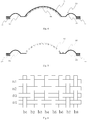
- the woven structure of the carbon fiber cloth may be a plain woven structure.
- the plain woven structure is that the longitude lines sink and emerge in the latitude lines alternately in the latitude direction, and the sinking and emerging of adjacent longitude lines are opposite.
- longitude lines are a1-a4
- latitude lines are b1-b8. Since the carbon fiber lines are woven alternately in longitude and latitude directions, the plain carbon fiber cloth has the same elasticity in the two directions.
- the texture of the plain fabric is firm and flat in appearance. The size of the mesh can be adjusted according to actual needs.
- the woven structure of the carbon fiber cloth may also be a twill woven structure.
- the organization points of the twill woven structure are continuous to form diagonal lines.
- Fig. 7 shows an embodiment of a twill woven structure.
- Each latitude line sinks and emerges alternately above two longitude lines and also sinks and emerges alternately under two longitude lines.
- longitude lines are a1-a4, and latitude lines are b1-b8.
- the twill carbon fiber cloth has the same elastic strength in two directions.
- the vibration diaphragm body portion preferably adopts an isotropic material to ensure the isotropic property of the vibration system of the product.
- the isotropic vibration diaphragm material is for example TPU (Thermoplastic polyurethanes).
- the carbon fiber cloth may also be a woven structure combining plain and twill weaving.
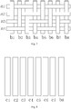
- the carbon fiber cloth layer is a unidirectional carbon fiber cloth, which means that each carbon fiber line is arranged in the same direction without intersection, such as carbon fiber lines c1-c8. Since the carbon fiber lines per se have directivity, the unidirectional carbon fiber cloth is directional in a two-dimensional space and has different elastic properties in two directions.
- the vibration diaphragm body portion preferably adopts an anisotropic material to ensure balanced vibration of the vibration system of the product without causing polarization.
- the anisotropic vibration diaphragm material is for example PEEK (Polyetheretherketone) or TPEE (Thermoplastic polyurethanes).
- the reinforcement portion may be obtained after performing hot pressing or other formation process on the carbon fiber cloth and then cutting the same.
- the reinforcement portion 100 may be of a flat plate shape, a dome shape, a straw hat shape and so on.
- the flat plate shape may be a rectangle, a circle or an oval.
- an embodiment of the present invention provides a speaker device, where the speaker device includes a vibration diaphragm mentioned above.
- the vibration diaphragm in an embodiment of the present invention adopts a carbon fiber cloth as the reinforcement portion (DOME). Since the carbon fiber cloth has the properties of low density, high strength and high modulus, it can sufficiently satisfy the performance requirements to the reinforcement portion by the vibration diaphragm and the acoustic performance requirements to the vibration diaphragm by the speaker device.
- the vibration diaphragm and the speaker device have the following technical effects.
Landscapes
- Engineering & Computer Science (AREA)
- Physics & Mathematics (AREA)
- Acoustics & Sound (AREA)
- Signal Processing (AREA)
- Multimedia (AREA)
- Manufacturing & Machinery (AREA)
- Diaphragms For Electromechanical Transducers (AREA)
Claims (11)
- Un diaphragme de vibration, comprenant une partie de corps (200) de diaphragme de vibration et une partie de renforcement (100) couplée au centre de la partie de corps de diaphragme de vibration (200), ladite partie de renforcement (100) comprenant une couche de tissu de fibres de carbone, caractérisé en ce que
ladite couche de tissu de fibres de carbone est un préimprégné en fibres de carbone, et que ladite partie de renforcement (100) est intégralement moulée par injection avec ladite partie de corps de diaphragme de vibration (200). - Ledit diaphragme de vibration selon la revendication 1, caractérisé en ce que ladite couche de tissu de fibres de carbone est un tissu de fibres de carbone tissé ou un tissu de fibres de carbone unidirectionnel, et que ledit tissu de fibres de carbone tissé est un tissu de fibres de carbone uni ou un tissu de fibres de carbone sergé.
- Ledit diaphragme de vibration selon l'une quelconque des revendications 1 à 2, caractérisé en ce que ladite couche de tissu de fibres de carbone est un tissu de fibres de carbone tissé et ladite partie de corps de diaphragme de vibration est en un matériau de diaphragme de vibration isotrope; ou que ladite couche de tissu de fibres de carbone est un tissu unidirectionnel de fibres de carbone et ladite partie de corps de diaphragme de vibration est en un matériau de diaphragme de vibration anisotrope.
- Ledit diaphragme de vibration selon l'une quelconque des revendications 1 à 3, caractérisé en ce que ladite couche de tissu de fibres de carbone est un tissu de fibres de carbone tissé et ladite partie de corps de diaphragme de vibration est en un matériau TPU; ou que ladite couche de tissu de fibres de carbone est une couche unidirectionnel et ladite partie de corps de diaphragme de vibration est en un matériau PEEK; ou que ladite couche de tissu de fibres de carbone est une couche unidirectionnel et ladite partie de corps de diaphragme de vibration est en un matériau TPEE.
- Ledit diaphragme de vibration selon l'une quelconque des revendications 1 à 4, caractérisé en ce que ladite couche de tissu de fibres de carbone comprend une pluralité de couches de tissu de fibres de carbone laminées ensemble.
- Ledit diaphragme de vibration selon l'une quelconque des revendications 1 à 5, caractérisé en ce que la forme de ladite partie de renforcement est l'une quelconque des suivantes: un type à plaque plate, un type à dôme et un type à chapeau de paille.
- Ledit diaphragme de vibration selon l'une quelconque des revendications 1 à 6, caractérisé en ce que ladite partie de corps de diaphragme de vibration est en un matériau polymère ou en un matériau de caoutchouc silicone.
- Ledit diaphragme de vibration selon l'une quelconque des revendications 1 à 7, caractérisé en ce que ladite partie de corps de diaphragme de vibration est en un matériau polymère et ladite partie de renforcement est collée à ladite partie de corps de diaphragme de vibration; ou que ladite partie de corps de diaphragme de vibration est en un matériau polymère et ladite partie de renforcement est intégralement formée par pression chaude avec ladite partie de corps de diaphragme de vibration; ou que ladite partie de corps de diaphragme de vibration est en un matériau de caoutchouc silicone et ladite partie de renforcement est intégralement moulée par injection avec ladite partie de corps de diaphragme de vibration.
- Ledit diaphragme de vibration selon l'une quelconque des revendications 1 à 8, caractérisé en ce que ladite partie de corps de diaphragme de vibration comprend une partie centrale (201) située au centre et un anneau (202) au bord, la forme de la partie de ladite partie centrale (201) faisant face à ladite partie de renforcement est identique à celle de ladite partie de renforcement, et ladite partie de renforcement est intégralement formée avec ladite partie de corps de diaphragme de vibration.
- Ledit diaphragme de vibration selon l'une quelconque des revendications 1 à 8, caractérisé en ce que ladite partie de corps de diaphragme de vibration comprend une partie centrale (201) située au centre et un anneau (202) au bord, ladite partie centrale (201) est pourvue d'un évidement et ladite partie de renforcement est incorporée dans ledit évidement, et ladite partie de renforcement est intégralement formée avec ladite partie de corps de diaphragme de vibration.
- Un dispositif de haut-parleur, caractérisé en ce qu'il comprend un diaphragme de vibration selon l'une quelconque des revendications 1 à 10.
Applications Claiming Priority (2)
| Application Number | Priority Date | Filing Date | Title |
|---|---|---|---|
| CN201510106182.5A CN104703100A (zh) | 2015-03-11 | 2015-03-11 | 一种振膜以及一种扬声器装置 |
| PCT/CN2015/097753 WO2016141745A1 (fr) | 2015-03-11 | 2015-12-17 | Membrane et appareil haut-parleur |
Publications (3)
| Publication Number | Publication Date |
|---|---|
| EP3247131A1 EP3247131A1 (fr) | 2017-11-22 |
| EP3247131A4 EP3247131A4 (fr) | 2017-12-13 |
| EP3247131B1 true EP3247131B1 (fr) | 2019-09-25 |
Family
ID=53349798
Family Applications (1)
| Application Number | Title | Priority Date | Filing Date |
|---|---|---|---|
| EP15884423.3A Active EP3247131B1 (fr) | 2015-03-11 | 2015-12-17 | Membrane et appareil haut-parleur |
Country Status (4)
| Country | Link |
|---|---|
| US (1) | US20180270578A1 (fr) |
| EP (1) | EP3247131B1 (fr) |
| CN (1) | CN104703100A (fr) |
| WO (1) | WO2016141745A1 (fr) |
Families Citing this family (17)
| Publication number | Priority date | Publication date | Assignee | Title |
|---|---|---|---|---|
| CN104703100A (zh) * | 2015-03-11 | 2015-06-10 | 歌尔声学股份有限公司 | 一种振膜以及一种扬声器装置 |
| GB2549955A (en) * | 2016-05-03 | 2017-11-08 | 4A Mfg Gmbh | Membrane plate structure for generating sound waves |
| CN106792379A (zh) * | 2017-01-20 | 2017-05-31 | 瑞声光电科技(常州)有限公司 | 碳纤维球顶、碳纤维球顶的制作方法及扬声器 |
| CN106792376A (zh) * | 2017-01-20 | 2017-05-31 | 瑞声光电科技(常州)有限公司 | 碳纤维球顶、碳纤维球顶的制作方法及扬声器 |
| CN106851523A (zh) * | 2017-01-22 | 2017-06-13 | 瑞声科技(新加坡)有限公司 | 碳纤维编织球顶、振膜结构及制作方法 |
| CN107903630A (zh) * | 2017-12-07 | 2018-04-13 | 歌尔股份有限公司 | 用于发声装置的振膜及其制备方法 |
| CN108391214A (zh) * | 2018-05-23 | 2018-08-10 | 歌尔股份有限公司 | 振动系统及扬声器 |
| JP7091142B2 (ja) * | 2018-05-23 | 2022-06-27 | アルパイン株式会社 | 電気音響変換装置 |
| CN109246553B (zh) * | 2018-11-09 | 2021-03-30 | 歌尔股份有限公司 | 一种应用于扬声器振膜的补强部及振膜 |
| CN109862490B (zh) * | 2018-12-30 | 2021-07-09 | 瑞声声学科技(深圳)有限公司 | 扬声器 |
| CN110324764A (zh) * | 2019-07-16 | 2019-10-11 | 陈新得 | 一种扬声器振膜 |
| KR102209486B1 (ko) * | 2019-10-29 | 2021-01-29 | 주식회사 이엠텍 | 리시버의 진동판 부착 구조 |
| CN110784807B (zh) * | 2019-10-31 | 2021-07-06 | 歌尔股份有限公司 | 一种发声装置的振膜以及发声装置 |
| WO2021128118A1 (fr) * | 2019-12-26 | 2021-07-01 | 瑞声科技(新加坡)有限公司 | Dôme de diaphragme |
| CN111711897B (zh) | 2020-08-20 | 2020-12-08 | 歌尔股份有限公司 | 一种发声装置模组 |
| CN111711896B (zh) * | 2020-08-20 | 2020-11-20 | 歌尔股份有限公司 | 一种发声装置模组 |
| CN120529238B (zh) * | 2025-07-18 | 2025-09-23 | 诺兰特新材料(北京)有限公司 | 用于车载音响的玻纤喇叭振膜 |
Family Cites Families (33)
| Publication number | Priority date | Publication date | Assignee | Title |
|---|---|---|---|---|
| US4410768A (en) * | 1980-07-23 | 1983-10-18 | Nippon Gakki Seizo Kabushiki Kaisha | Electro-acoustic transducer |
| JPS58222700A (ja) * | 1982-06-18 | 1983-12-24 | Matsushita Electric Ind Co Ltd | 平面スピ−カ |
| US4552243A (en) * | 1984-05-03 | 1985-11-12 | Pioneer Industrial Components, Inc. | Diaphragm material for acoustical transducer |
| JPS63226689A (ja) * | 1986-10-17 | 1988-09-21 | 林 顕 | 発音用振動板 |
| US5031720A (en) * | 1987-12-01 | 1991-07-16 | Kabushiki Kaisha Kenwood | Speaker diaphragm |
| US5329072A (en) * | 1991-05-23 | 1994-07-12 | Yamaha Corporation | Acoustic diaphragm |
| EP0632675B1 (fr) * | 1993-06-28 | 2001-08-16 | Matsushita Electric Industrial Co., Ltd. | Pièces moulées intégrales de membrane-suspension pour haut-parleurs transducteurs acoustiques comprenant les mêmes et procédé pour leur fabrication |
| CN1134650A (zh) * | 1995-04-28 | 1996-10-30 | 许荣初 | 扬声器圆锥振膜 |
| WO2004098236A1 (fr) * | 1999-01-27 | 2004-11-11 | Toshihide Inoue | Membrane de haut-parleur |
| US6390232B1 (en) * | 1999-10-29 | 2002-05-21 | Communications Products Corporation | Speaker cone assembly |
| TW494060B (en) * | 2000-04-14 | 2002-07-11 | John T S Lin | Molding method of carbon fiber layer |
| FR2853803B1 (fr) * | 2003-04-09 | 2005-06-03 | Focal Jmlab | Membrane pour haut-parleur d'enceinte acoustique haute fidelite, multicouches, multimateriaux |
| GB2403091B (en) * | 2003-06-18 | 2006-08-09 | B & W Loudspeakers | Diaphragms for loudspeaker drive units |
| JP2005303909A (ja) * | 2004-04-15 | 2005-10-27 | Pioneer Electronic Corp | スピーカ用振動板及びスピーカ |
| JP2005303911A (ja) * | 2004-04-15 | 2005-10-27 | Pioneer Electronic Corp | スピーカ用振動板及びスピーカ |
| JP4482372B2 (ja) * | 2004-05-13 | 2010-06-16 | パイオニア株式会社 | 電気音響変換器用振動板の製造方法 |
| JP2006325125A (ja) * | 2005-05-20 | 2006-11-30 | Pioneer Electronic Corp | スピーカ用振動板及びその製造方法 |
| JP2007318405A (ja) * | 2006-05-25 | 2007-12-06 | Pioneer Electronic Corp | 電気音響変換器用振動板 |
| WO2009008173A1 (fr) * | 2007-07-12 | 2009-01-15 | Panasonic Corporation | Membrane de haut-parleur, haut-parleur utilisant cette membrane et procédé de fabrication de membrane de haut-parleur |
| EP2234408A4 (fr) * | 2008-01-22 | 2013-09-25 | Panasonic Corp | Membrane de haut-parleur, haut-parleur utilisant ladite membrane et procédé de fabrication d'une membrane de haut-parleur |
| JP4783399B2 (ja) * | 2008-06-04 | 2011-09-28 | ホシデン株式会社 | ドーム型振動板及びこれを用いたスピーカ |
| CN101990147B (zh) * | 2009-07-31 | 2013-08-28 | 清华大学 | 振动膜及应用该振动膜的扬声器 |
| CN101990148B (zh) * | 2009-07-31 | 2013-08-21 | 清华大学 | 振动膜及应用该振动膜的扬声器 |
| CN101778324A (zh) * | 2009-12-25 | 2010-07-14 | 金旭芳 | 扬声器振动音膜 |
| CN201839422U (zh) * | 2010-08-06 | 2011-05-18 | 东莞大朗后声电子厂 | 平板鼓纸 |
| CN102454035A (zh) * | 2010-10-29 | 2012-05-16 | 威海光威复合材料有限公司 | 0度及90度角双轴向碳纤维经编布 |
| CN102454034A (zh) * | 2010-10-29 | 2012-05-16 | 威海光威复合材料有限公司 | ±45度角双轴向碳纤维经编布 |
| CN102454039A (zh) * | 2010-10-29 | 2012-05-16 | 威海光威复合材料有限公司 | 90度角碳纤维经编布 |
| US9619028B2 (en) * | 2012-03-29 | 2017-04-11 | Kyocera Corporation | Electronic apparatus and panel unit |
| CN202873041U (zh) * | 2012-09-26 | 2013-04-10 | 瑞声光电科技(常州)有限公司 | 复合振膜及应用所述复合振膜的扬声器 |
| CN204442650U (zh) * | 2015-03-11 | 2015-07-01 | 歌尔声学股份有限公司 | 一种振膜以及一种扬声器装置 |
| CN104703100A (zh) * | 2015-03-11 | 2015-06-10 | 歌尔声学股份有限公司 | 一种振膜以及一种扬声器装置 |
| CN204442651U (zh) * | 2015-03-11 | 2015-07-01 | 歌尔声学股份有限公司 | 一种振膜以及一种扬声器装置 |
-
2015
- 2015-03-11 CN CN201510106182.5A patent/CN104703100A/zh active Pending
- 2015-12-17 US US15/556,091 patent/US20180270578A1/en not_active Abandoned
- 2015-12-17 WO PCT/CN2015/097753 patent/WO2016141745A1/fr not_active Ceased
- 2015-12-17 EP EP15884423.3A patent/EP3247131B1/fr active Active
Non-Patent Citations (1)
| Title |
|---|
| None * |
Also Published As
| Publication number | Publication date |
|---|---|
| CN104703100A (zh) | 2015-06-10 |
| US20180270578A1 (en) | 2018-09-20 |
| EP3247131A1 (fr) | 2017-11-22 |
| EP3247131A4 (fr) | 2017-12-13 |
| WO2016141745A1 (fr) | 2016-09-15 |
Similar Documents
| Publication | Publication Date | Title |
|---|---|---|
| EP3247131B1 (fr) | Membrane et appareil haut-parleur | |
| US9913043B2 (en) | Loudspeaker vibration system | |
| US10856083B2 (en) | Diaphragm and miniature speaker comprising same | |
| CN207968945U (zh) | 碳纤维球顶及扬声器 | |
| US20180302721A1 (en) | Carbon Fiber Dome and Manufacturing Method for Same | |
| US9113250B2 (en) | Speaker with diaphragm arrangement | |
| CN103475981A (zh) | 扬声器振动系统 | |
| TW201818731A (zh) | 適用於揚聲器的振膜 | |
| JP2016524669A5 (fr) | ||
| CN108859296B (zh) | 复合膜结构、振膜和发声装置 | |
| CN204442650U (zh) | 一种振膜以及一种扬声器装置 | |
| US10034093B2 (en) | Temperature stable membrane plate structure for a loudspeaker | |
| CN106060722A (zh) | 石墨烯振膜、振膜制作方法及包括该振膜的传声器 | |
| CN103347233A (zh) | 扬声器振膜 | |
| CN110677783A (zh) | 一种发泡体材料、振动板以及扬声器 | |
| WO2022166367A1 (fr) | Plaque vibrante, son procédé de traitement, structure de haut-parleur et dispositif électronique | |
| CN204442651U (zh) | 一种振膜以及一种扬声器装置 | |
| CN112752200B (zh) | 用于接收器的隔膜的结合结构 | |
| US20200314575A1 (en) | Diaphragm, method for manufacturing same, and speaker using same | |
| US11039252B2 (en) | Membrane plate structure for generating sound waves | |
| CN118283497A (zh) | 发声装置 | |
| JP3190533U (ja) | 繊維強化シート | |
| CN204697281U (zh) | 扬声器振膜 | |
| CN203590434U (zh) | 扬声器振动系统 | |
| JP5752922B2 (ja) | フィルム状部材及びその貼り付け方法 |
Legal Events
| Date | Code | Title | Description |
|---|---|---|---|
| STAA | Information on the status of an ep patent application or granted ep patent |
Free format text: STATUS: THE INTERNATIONAL PUBLICATION HAS BEEN MADE |
|
| PUAI | Public reference made under article 153(3) epc to a published international application that has entered the european phase |
Free format text: ORIGINAL CODE: 0009012 |
|
| STAA | Information on the status of an ep patent application or granted ep patent |
Free format text: STATUS: REQUEST FOR EXAMINATION WAS MADE |
|
| 17P | Request for examination filed |
Effective date: 20170818 |
|
| AK | Designated contracting states |
Kind code of ref document: A1 Designated state(s): AL AT BE BG CH CY CZ DE DK EE ES FI FR GB GR HR HU IE IS IT LI LT LU LV MC MK MT NL NO PL PT RO RS SE SI SK SM TR |
|
| AX | Request for extension of the european patent |
Extension state: BA ME |
|
| A4 | Supplementary search report drawn up and despatched |
Effective date: 20171110 |
|
| RIC1 | Information provided on ipc code assigned before grant |
Ipc: H04R 7/12 20060101ALN20171106BHEP Ipc: H04R 31/00 20060101ALI20171106BHEP Ipc: H04R 7/06 20060101AFI20171106BHEP |
|
| STAA | Information on the status of an ep patent application or granted ep patent |
Free format text: STATUS: EXAMINATION IS IN PROGRESS |
|
| DAX | Request for extension of the european patent (deleted) | ||
| RAP1 | Party data changed (applicant data changed or rights of an application transferred) |
Owner name: GOERTEK.INC |
|
| 17Q | First examination report despatched |
Effective date: 20180219 |
|
| DAV | Request for validation of the european patent (deleted) | ||
| GRAP | Despatch of communication of intention to grant a patent |
Free format text: ORIGINAL CODE: EPIDOSNIGR1 |
|
| RIC1 | Information provided on ipc code assigned before grant |
Ipc: H04R 7/06 20060101AFI20190416BHEP Ipc: H04R 31/00 20060101ALI20190416BHEP Ipc: H04R 7/12 20060101ALN20190416BHEP |
|
| STAA | Information on the status of an ep patent application or granted ep patent |
Free format text: STATUS: GRANT OF PATENT IS INTENDED |
|
| INTG | Intention to grant announced |
Effective date: 20190523 |
|
| GRAS | Grant fee paid |
Free format text: ORIGINAL CODE: EPIDOSNIGR3 |
|
| GRAA | (expected) grant |
Free format text: ORIGINAL CODE: 0009210 |
|
| STAA | Information on the status of an ep patent application or granted ep patent |
Free format text: STATUS: THE PATENT HAS BEEN GRANTED |
|
| AK | Designated contracting states |
Kind code of ref document: B1 Designated state(s): AL AT BE BG CH CY CZ DE DK EE ES FI FR GB GR HR HU IE IS IT LI LT LU LV MC MK MT NL NO PL PT RO RS SE SI SK SM TR |
|
| REG | Reference to a national code |
Ref country code: GB Ref legal event code: FG4D |
|
| REG | Reference to a national code |
Ref country code: CH Ref legal event code: EP |
|
| REG | Reference to a national code |
Ref country code: AT Ref legal event code: REF Ref document number: 1185021 Country of ref document: AT Kind code of ref document: T Effective date: 20191015 |
|
| REG | Reference to a national code |
Ref country code: IE Ref legal event code: FG4D |
|
| REG | Reference to a national code |
Ref country code: DE Ref legal event code: R096 Ref document number: 602015038875 Country of ref document: DE |
|
| REG | Reference to a national code |
Ref country code: NL Ref legal event code: MP Effective date: 20190925 |
|
| PG25 | Lapsed in a contracting state [announced via postgrant information from national office to epo] |
Ref country code: HR Free format text: LAPSE BECAUSE OF FAILURE TO SUBMIT A TRANSLATION OF THE DESCRIPTION OR TO PAY THE FEE WITHIN THE PRESCRIBED TIME-LIMIT Effective date: 20190925 Ref country code: LT Free format text: LAPSE BECAUSE OF FAILURE TO SUBMIT A TRANSLATION OF THE DESCRIPTION OR TO PAY THE FEE WITHIN THE PRESCRIBED TIME-LIMIT Effective date: 20190925 Ref country code: NO Free format text: LAPSE BECAUSE OF FAILURE TO SUBMIT A TRANSLATION OF THE DESCRIPTION OR TO PAY THE FEE WITHIN THE PRESCRIBED TIME-LIMIT Effective date: 20191225 Ref country code: BG Free format text: LAPSE BECAUSE OF FAILURE TO SUBMIT A TRANSLATION OF THE DESCRIPTION OR TO PAY THE FEE WITHIN THE PRESCRIBED TIME-LIMIT Effective date: 20191225 Ref country code: FI Free format text: LAPSE BECAUSE OF FAILURE TO SUBMIT A TRANSLATION OF THE DESCRIPTION OR TO PAY THE FEE WITHIN THE PRESCRIBED TIME-LIMIT Effective date: 20190925 Ref country code: SE Free format text: LAPSE BECAUSE OF FAILURE TO SUBMIT A TRANSLATION OF THE DESCRIPTION OR TO PAY THE FEE WITHIN THE PRESCRIBED TIME-LIMIT Effective date: 20190925 |
|
| REG | Reference to a national code |
Ref country code: LT Ref legal event code: MG4D |
|
| PG25 | Lapsed in a contracting state [announced via postgrant information from national office to epo] |
Ref country code: RS Free format text: LAPSE BECAUSE OF FAILURE TO SUBMIT A TRANSLATION OF THE DESCRIPTION OR TO PAY THE FEE WITHIN THE PRESCRIBED TIME-LIMIT Effective date: 20190925 Ref country code: LV Free format text: LAPSE BECAUSE OF FAILURE TO SUBMIT A TRANSLATION OF THE DESCRIPTION OR TO PAY THE FEE WITHIN THE PRESCRIBED TIME-LIMIT Effective date: 20190925 Ref country code: GR Free format text: LAPSE BECAUSE OF FAILURE TO SUBMIT A TRANSLATION OF THE DESCRIPTION OR TO PAY THE FEE WITHIN THE PRESCRIBED TIME-LIMIT Effective date: 20191226 |
|
| REG | Reference to a national code |
Ref country code: AT Ref legal event code: MK05 Ref document number: 1185021 Country of ref document: AT Kind code of ref document: T Effective date: 20190925 |
|
| PG25 | Lapsed in a contracting state [announced via postgrant information from national office to epo] |
Ref country code: AT Free format text: LAPSE BECAUSE OF FAILURE TO SUBMIT A TRANSLATION OF THE DESCRIPTION OR TO PAY THE FEE WITHIN THE PRESCRIBED TIME-LIMIT Effective date: 20190925 Ref country code: NL Free format text: LAPSE BECAUSE OF FAILURE TO SUBMIT A TRANSLATION OF THE DESCRIPTION OR TO PAY THE FEE WITHIN THE PRESCRIBED TIME-LIMIT Effective date: 20190925 Ref country code: AL Free format text: LAPSE BECAUSE OF FAILURE TO SUBMIT A TRANSLATION OF THE DESCRIPTION OR TO PAY THE FEE WITHIN THE PRESCRIBED TIME-LIMIT Effective date: 20190925 Ref country code: EE Free format text: LAPSE BECAUSE OF FAILURE TO SUBMIT A TRANSLATION OF THE DESCRIPTION OR TO PAY THE FEE WITHIN THE PRESCRIBED TIME-LIMIT Effective date: 20190925 Ref country code: RO Free format text: LAPSE BECAUSE OF FAILURE TO SUBMIT A TRANSLATION OF THE DESCRIPTION OR TO PAY THE FEE WITHIN THE PRESCRIBED TIME-LIMIT Effective date: 20190925 Ref country code: IT Free format text: LAPSE BECAUSE OF FAILURE TO SUBMIT A TRANSLATION OF THE DESCRIPTION OR TO PAY THE FEE WITHIN THE PRESCRIBED TIME-LIMIT Effective date: 20190925 Ref country code: PT Free format text: LAPSE BECAUSE OF FAILURE TO SUBMIT A TRANSLATION OF THE DESCRIPTION OR TO PAY THE FEE WITHIN THE PRESCRIBED TIME-LIMIT Effective date: 20200127 Ref country code: PL Free format text: LAPSE BECAUSE OF FAILURE TO SUBMIT A TRANSLATION OF THE DESCRIPTION OR TO PAY THE FEE WITHIN THE PRESCRIBED TIME-LIMIT Effective date: 20190925 Ref country code: ES Free format text: LAPSE BECAUSE OF FAILURE TO SUBMIT A TRANSLATION OF THE DESCRIPTION OR TO PAY THE FEE WITHIN THE PRESCRIBED TIME-LIMIT Effective date: 20190925 |
|
| PG25 | Lapsed in a contracting state [announced via postgrant information from national office to epo] |
Ref country code: SK Free format text: LAPSE BECAUSE OF FAILURE TO SUBMIT A TRANSLATION OF THE DESCRIPTION OR TO PAY THE FEE WITHIN THE PRESCRIBED TIME-LIMIT Effective date: 20190925 Ref country code: IS Free format text: LAPSE BECAUSE OF FAILURE TO SUBMIT A TRANSLATION OF THE DESCRIPTION OR TO PAY THE FEE WITHIN THE PRESCRIBED TIME-LIMIT Effective date: 20200224 Ref country code: CZ Free format text: LAPSE BECAUSE OF FAILURE TO SUBMIT A TRANSLATION OF THE DESCRIPTION OR TO PAY THE FEE WITHIN THE PRESCRIBED TIME-LIMIT Effective date: 20190925 Ref country code: SM Free format text: LAPSE BECAUSE OF FAILURE TO SUBMIT A TRANSLATION OF THE DESCRIPTION OR TO PAY THE FEE WITHIN THE PRESCRIBED TIME-LIMIT Effective date: 20190925 |
|
| REG | Reference to a national code |
Ref country code: DE Ref legal event code: R097 Ref document number: 602015038875 Country of ref document: DE |
|
| PG2D | Information on lapse in contracting state deleted |
Ref country code: IS |
|
| PG25 | Lapsed in a contracting state [announced via postgrant information from national office to epo] |
Ref country code: DK Free format text: LAPSE BECAUSE OF FAILURE TO SUBMIT A TRANSLATION OF THE DESCRIPTION OR TO PAY THE FEE WITHIN THE PRESCRIBED TIME-LIMIT Effective date: 20190925 Ref country code: IS Free format text: LAPSE BECAUSE OF FAILURE TO SUBMIT A TRANSLATION OF THE DESCRIPTION OR TO PAY THE FEE WITHIN THE PRESCRIBED TIME-LIMIT Effective date: 20200126 |
|
| PLBE | No opposition filed within time limit |
Free format text: ORIGINAL CODE: 0009261 |
|
| REG | Reference to a national code |
Ref country code: CH Ref legal event code: PL |
|
| STAA | Information on the status of an ep patent application or granted ep patent |
Free format text: STATUS: NO OPPOSITION FILED WITHIN TIME LIMIT |
|
| REG | Reference to a national code |
Ref country code: BE Ref legal event code: MM Effective date: 20191231 |
|
| PG25 | Lapsed in a contracting state [announced via postgrant information from national office to epo] |
Ref country code: MC Free format text: LAPSE BECAUSE OF FAILURE TO SUBMIT A TRANSLATION OF THE DESCRIPTION OR TO PAY THE FEE WITHIN THE PRESCRIBED TIME-LIMIT Effective date: 20190925 |
|
| 26N | No opposition filed |
Effective date: 20200626 |
|
| PG25 | Lapsed in a contracting state [announced via postgrant information from national office to epo] |
Ref country code: LU Free format text: LAPSE BECAUSE OF NON-PAYMENT OF DUE FEES Effective date: 20191217 Ref country code: IE Free format text: LAPSE BECAUSE OF NON-PAYMENT OF DUE FEES Effective date: 20191217 |
|
| PG25 | Lapsed in a contracting state [announced via postgrant information from national office to epo] |
Ref country code: LI Free format text: LAPSE BECAUSE OF NON-PAYMENT OF DUE FEES Effective date: 20191231 Ref country code: SI Free format text: LAPSE BECAUSE OF FAILURE TO SUBMIT A TRANSLATION OF THE DESCRIPTION OR TO PAY THE FEE WITHIN THE PRESCRIBED TIME-LIMIT Effective date: 20190925 Ref country code: CH Free format text: LAPSE BECAUSE OF NON-PAYMENT OF DUE FEES Effective date: 20191231 Ref country code: BE Free format text: LAPSE BECAUSE OF NON-PAYMENT OF DUE FEES Effective date: 20191231 |
|
| PG25 | Lapsed in a contracting state [announced via postgrant information from national office to epo] |
Ref country code: CY Free format text: LAPSE BECAUSE OF FAILURE TO SUBMIT A TRANSLATION OF THE DESCRIPTION OR TO PAY THE FEE WITHIN THE PRESCRIBED TIME-LIMIT Effective date: 20190925 |
|
| PG25 | Lapsed in a contracting state [announced via postgrant information from national office to epo] |
Ref country code: MT Free format text: LAPSE BECAUSE OF FAILURE TO SUBMIT A TRANSLATION OF THE DESCRIPTION OR TO PAY THE FEE WITHIN THE PRESCRIBED TIME-LIMIT Effective date: 20190925 Ref country code: HU Free format text: LAPSE BECAUSE OF FAILURE TO SUBMIT A TRANSLATION OF THE DESCRIPTION OR TO PAY THE FEE WITHIN THE PRESCRIBED TIME-LIMIT; INVALID AB INITIO Effective date: 20151217 |
|
| PG25 | Lapsed in a contracting state [announced via postgrant information from national office to epo] |
Ref country code: TR Free format text: LAPSE BECAUSE OF FAILURE TO SUBMIT A TRANSLATION OF THE DESCRIPTION OR TO PAY THE FEE WITHIN THE PRESCRIBED TIME-LIMIT Effective date: 20190925 |
|
| PG25 | Lapsed in a contracting state [announced via postgrant information from national office to epo] |
Ref country code: MK Free format text: LAPSE BECAUSE OF FAILURE TO SUBMIT A TRANSLATION OF THE DESCRIPTION OR TO PAY THE FEE WITHIN THE PRESCRIBED TIME-LIMIT Effective date: 20190925 |
|
| PGFP | Annual fee paid to national office [announced via postgrant information from national office to epo] |
Ref country code: GB Payment date: 20251229 Year of fee payment: 11 |
|
| PGFP | Annual fee paid to national office [announced via postgrant information from national office to epo] |
Ref country code: FR Payment date: 20251230 Year of fee payment: 11 |
|
| PGFP | Annual fee paid to national office [announced via postgrant information from national office to epo] |
Ref country code: DE Payment date: 20251231 Year of fee payment: 11 |