EP3247208B1 - Vorrichtung zur halterung eines köders, insbesondere eines köders für nagetiere - Google Patents
Vorrichtung zur halterung eines köders, insbesondere eines köders für nagetiere Download PDFInfo
- Publication number
- EP3247208B1 EP3247208B1 EP15720580.8A EP15720580A EP3247208B1 EP 3247208 B1 EP3247208 B1 EP 3247208B1 EP 15720580 A EP15720580 A EP 15720580A EP 3247208 B1 EP3247208 B1 EP 3247208B1
- Authority
- EP
- European Patent Office
- Prior art keywords
- housing part
- bait
- platform
- fastening
- water
- Prior art date
- Legal status (The legal status is an assumption and is not a legal conclusion. Google has not performed a legal analysis and makes no representation as to the accuracy of the status listed.)
- Active
Links
Images












Classifications
-
- A—HUMAN NECESSITIES
- A01—AGRICULTURE; FORESTRY; ANIMAL HUSBANDRY; HUNTING; TRAPPING; FISHING
- A01M—CATCHING, TRAPPING OR SCARING OF ANIMALS; APPARATUS FOR THE DESTRUCTION OF NOXIOUS ANIMALS OR NOXIOUS PLANTS
- A01M25/00—Devices for dispensing poison for animals
-
- A—HUMAN NECESSITIES
- A01—AGRICULTURE; FORESTRY; ANIMAL HUSBANDRY; HUNTING; TRAPPING; FISHING
- A01M—CATCHING, TRAPPING OR SCARING OF ANIMALS; APPARATUS FOR THE DESTRUCTION OF NOXIOUS ANIMALS OR NOXIOUS PLANTS
- A01M25/00—Devices for dispensing poison for animals
- A01M25/002—Bait holders, i.e. stationary devices for holding poisonous bait at the disposal of the animal
- A01M25/004—Bait stations, i.e. boxes completely enclosing the bait and provided with animal entrances
-
- A—HUMAN NECESSITIES
- A01—AGRICULTURE; FORESTRY; ANIMAL HUSBANDRY; HUNTING; TRAPPING; FISHING
- A01M—CATCHING, TRAPPING OR SCARING OF ANIMALS; APPARATUS FOR THE DESTRUCTION OF NOXIOUS ANIMALS OR NOXIOUS PLANTS
- A01M25/00—Devices for dispensing poison for animals
- A01M25/002—Bait holders, i.e. stationary devices for holding poisonous bait at the disposal of the animal
-
- A—HUMAN NECESSITIES
- A01—AGRICULTURE; FORESTRY; ANIMAL HUSBANDRY; HUNTING; TRAPPING; FISHING
- A01M—CATCHING, TRAPPING OR SCARING OF ANIMALS; APPARATUS FOR THE DESTRUCTION OF NOXIOUS ANIMALS OR NOXIOUS PLANTS
- A01M1/00—Stationary means for catching or killing insects
- A01M1/20—Poisoning, narcotising, or burning insects
- A01M1/2005—Poisoning insects using bait stations
Definitions
- the invention relates to a device for holding a bait, in particular a bait for rodents.
- Such devices are for pest control, i. H. especially the control of rodents, such as. B. mice and rats, which are in water-flow channels or lines, d. H. in particular sewage, rainwater or dirty water channels and / or cable channels, or corresponding sewer or conduit shafts, d. H. generally in water-bearing facilities, and there considerable damage, e.g. B. on wastewater technology and other infrastructural facilities.
- rodents such as. B. mice and rats
- rodents such as. B. mice and rats
- rodents such as. B. mice and rats
- Corresponding devices therefore hold, typically pest-specific, baits which contain special poisons or active ingredients which, in various ways, bring about the death of the pests and / or prevent the pests from multiplying.
- the poisons or active ingredients contained in the baits generally represent a hazard for humans and nature, so care must be taken to ensure that they do not get into the water flowing through the corresponding channels or channel shafts and contaminate them. against such contamination, conventional devices offer large amounts of water and thus high water levels in the channels or manholes. B. is the case after heavy rain, insufficient protection.
- FR 2 516 747 A1 discloses a floating raft-like device for receiving a bait.
- WO 2009/056817 A2 discloses the use of a horizontally stored car tire to hold a bait.
- the invention is therefore based on the object of specifying an improved device for holding a bait, in particular a bait for rodents.
- the object is achieved by a device according to claim 1.
- the principle of the invention relates to a specially designed device for holding a bait for pests, ie in particular a bait for rodents, such as. B. mice and rats.
- the bait contains certain, typically pest-specific, substances, such as B. poisons or active ingredients that cause the pests to die and / or prevent the pests from multiplying in various ways.
- the term pest is also used below; this includes in particular rodents, such as. B. mice and rats to understand.
- the device according to the invention comprises a housing part.
- the housing part is in a channel or a manhole, such as. B. a sewer shaft and / or a cable duct shaft can be used.
- Water or waste water is typically located in the sewer or sewer shaft, or water or waste water may flow through the sewer or sewer shaft at least at times.
- manhole is used.
- a water-carrying facility such as. B. a sewer for water, d. H. e.g. B. wastewater, rainwater, dirty water, or supply lines, etc. to understand.
- the housing part inserted into the sewer shaft it expediently has a fastening device by means of which it, in particular detachably, on a wall of the sewer shaft or riser-side climbing devices, such as, for. B. duct shaft crampons can be attached.
- the fastening device can, for. B. include bolt-like, hook-like or profile-like fastening elements in order to fasten the housing part and thus the device as a whole to or in a wall of the sewer shaft or corresponding climbing devices.
- the housing part is typically made of a corrosion-resistant material, such as. B. a stainless steel (sheet) and / or plastic. Different sections of the housing part can be formed from different materials. In particular for the design of the or a section of the housing part made of plastic, the fact that a transparent plastic material can be used here to, for. B. for the purpose of checking a bait bite to provide necessary insight into the housing part.
- a corrosion-resistant material such as. B. a stainless steel (sheet) and / or plastic.
- Different sections of the housing part can be formed from different materials.
- a transparent plastic material can be used here to, for. B. for the purpose of checking a bait bite to provide necessary insight into the housing part.
- the housing part is typically, but not necessarily, hollow-cylindrical, i. H. it typically delimits a cylindrical receiving space in which certain components of the device can be received or received.
- the housing part can, for. B. on an end face, can be closed or closed by a cover element, so that access to the housing part-side receiving space can be created by removing the cover element.
- the cover element can have a threaded section, the housing part can have a threaded section that is opposite to this, so that the cover element can be screwed to the housing part.
- At least one, possibly several, ie at least two, bait platform (s) is arranged or formed within the housing part.
- Respective bait platforms each limit at least one through opening.
- Respective through openings are dimensioned such that a pest can pass them.
- Respective through openings define a lower area lying below a respective bait platform and an upper area located above a respective bait platform.
- the or a bait is typically arranged in a respective upper area.
- the or a bait can be arranged directly on a bait platform.
- the or at least one bait can also be arranged on a bait holding device for holding a bait.
- a bait held by a bait holding device does not have to be arranged lying directly on a corresponding bait platform.
- the housing part is expediently designed with at least one passage through which the pest can get into the housing part.
- a pest can also get out of the housing part via a corresponding passage.
- the passage allows access to a lower, i.e. H. below the (lowest) bait platform, area of the housing part.
- the pest that has entered the housing part must furthermore reach the bait platform equipped with the bait through at least one passage opening limited on the bait platform side. After the bait has been bitten, the pest can pass through at least one passage opening that is limited on the bait platform side into the lower region of the housing part and leave the device via appropriate passages.
- the or a further passage has access to an upper, ie. H. Above the (lowest) bait platform area of the housing part.
- a corresponding counter pressure means that the water rising in the housing part can be opposed to such a high back pressure that the water can no longer rise in the housing part given the current.
- respective bait platforms are typically arranged one above the other or one below the other.
- several bait platforms can be arranged in parallel, at least in sections.
- An intermediate space defining an intermediate level is typically formed between two (immediately) adjacent bait platforms.
- Respective gaps do not have to be the same in terms of their shape, volume, etc., but can be designed differently. This applies to the exemplary case of more than two bait platforms and thus at least two corresponding spaces.
- Respective gaps communicate with each other via passage openings limited on the bait platform side; there is therefore a passage from a "bottom" bait platform to a "top” bait platform.
- Gaps formed between corresponding bait platforms can cause a flow-related "calming down", generally influencing the flow, of water rising in the housing part.
- the water flowing into the housing part and rising in it has to "clear” its way here via several intermediate levels, which typically leads to a “calming down” of the flow of the water.
- At least one bait platform can also at least in sections with a surface structuring influencing the flow, in particular the type of flow or the flow velocity, of water flowing along it or rising in the housing part, e.g. B. in the form of flow-influencing ribs and / or beads.
- the presence of several bait platforms or gaps provides the possibility of equipping the housing part with a larger number of bait components than a housing part construction comprising only one (single) bait platform, since baits can in principle be arranged on several levels.
- the housing part can also be frequented by a larger number of pests.
- the mechanical stability, in particular the rigidity, of the housing part can be increased by the presence of several bait platforms or gaps.
- the housing part can additionally be "stiffened" by the bait platforms arranged in it.
- Respective through openings delimited by respective bait platforms can be arranged offset relative to one another.
- at least one passage opening of a first bait platform limited on the bait platform can be arranged offset from the at least one or at least one passage opening of a further bait platform arranged indirectly or directly adjacent to the first bait platform on the bait platform.
- a through opening of a first bait platform can be formed in an edge region of the first bait platform and a through opening of a further bait platform adjacent to the first bait platform can be formed in an opposite edge region of the further bait platform.
- Due to the staggered arrangement of respective through openings is also a "calming", generally influencing the flow, in the housing part, for. B. meandering, rising water possible.
- the staggered arrangement of respective through openings also facilitates the movement of pests between the respective spaces or intermediate levels.
- At least one bait platform can be formed at least in sections with an inclined or bent or curved relative to a horizontal plane or, if present, relative to at least one further, particularly adjacent, arranged further bait platform section.
- Appropriate inclined or curved or curved courses of a bait platform can also be used to influence the flow of water rising in the housing part.
- Inclined or curved or curved courses of corresponding bait platforms can also facilitate the emergence or descent of pests between the respective spaces or intermediate levels in the sense of ascent or descent ramps.
- At least one bait platform can be formed at least in sections with openings or perforations that cause it.
- Respective openings of a bait platform which are generally similar to a hole (sheet) structure, can "dampen" the flow of rising water and thus also “calm down".
- the openings are present in addition to the respective through openings and differ in particular in their size, ie in particular their diameter, from the respective through openings; the openings are small compared to the respective through openings.
- Round openings can for example have a diameter between 50 microns and 3 mm. Of course, different openings with different geometries can be present.
- At least one bait platform can be formed, at least in sections, spirally or helically, at least in sections, through the housing part.
- a pest that has penetrated into the housing part can move in a simple manner within the housing part via a correspondingly spiral or - similarly to a spiral staircase - helically designed bait platform, eg. B. to get a bait.
- Spiral or helical bait platforms can also have an influence on the flow of water rising in the housing part.
- This embodiment can be expedient in particular for a housing part construction comprising only one (single) bait platform, since a pest can be made to ascend and descend within the housing part via only one (single) correspondingly spiral or helical bait platform.
- this embodiment can also be useful in an analogous manner in connection with a housing part construction comprising several bait platforms.
- At least one bait can be arranged or arranged on a bait holding device for holding a bait.
- the device further comprises a bite detection device for detecting a bait bite.
- the bite detection device which is typically arranged in the housing part, is set up to generate at least acoustic and / or optical bite information when a bitten bait or a bait bite is detected and to output it via at least one output means. This makes it possible to detect a bait bite by a pest and to display it in a simple manner via acoustic and / or optical signals, which in turn can be expedient in the case of service or repair work.
- the bite detection device accordingly comprises a suitable sensor system for detecting a bait bite.
- the sensor system can detect, for example, the weight of the bait arranged on a bait holding device, bite-related weight changes, typically weight reductions, of the bait allowing conclusions to be drawn about a bait bite.
- the sensor system can detect bite-related forces acting on the bait and / or the bait holding device, typically tensile forces, which also allow conclusions to be drawn about a bait bite.
- the bite detection device can, depending on the bite information, for. B. based on the detection of the weight of the bait, generate different acoustic and / or optical signals.
- the weight of a new, not bitten bait can e.g. B. be signaled with optical signals of green color and / or with permanently constant optical signals output, the weight of a partially bitten bait z. B. signaled with optical signals of yellow color and / or with a first flashing frequency output optical signals, the bait is completely eaten, this can be done e.g. B. be signaled by optical signals of red color and / or with an optical signal output in comparison to the first flashing frequency higher second flashing frequency.
- An acoustic output means can e.g. B. be designed as a speaker or at least include one.
- An optical output means can e.g. B. as, in particular multicolored, light emitting diode or screen or comprise at least one (s).
- the or an output means can be arranged on or in the housing part, it being arranged on an exposed outer surface of the housing part or within a receiving space delimited by the housing part. In particular for optical output devices, if this is within the housing part, i. H. are arranged within a receiving space of the housing part delimited by the housing part, the housing part should be at least partially transparent, in order to make the optical signals recognizable from outside the housing part.
- the output means or an output means can also be integrated into an external mobile terminal. If the or an output means is integrated in an external mobile terminal, the closed position detection device and / or the bite detection device can be configured to communicate with the external mobile terminal and the closed position information and / or the bite information to the external mobile terminal for output at the external mobile terminal Transfer funds. Service or operating personnel can also enter z. B. be informed about a bait bite.
- the communication described is, in particular, radio-based, that is to say realized via Bluetooth, WLAN, etc., which is why the closed position detection device and / or the bite detection device comprise corresponding radio-based transmission devices.
- an external mobile device it can e.g. B. a cell phone, smartphone, tablet, notebook, etc.
- At least one receiving chamber is formed or arranged in the or a receiving space delimited by the housing part, in which electrical and / or electronic components of the device, in particular control devices and detection devices, can be arranged or arranged .
- the receiving chamber therefore offers protection of these components against external, ie. H. especially climatic and mechanical influences.
- the receiving chamber can be designed integrally with the housing part or as a separate component which is to be inserted separately in the housing part on the housing part side.
- the receiving chamber can be closed or closed by a cover element, which can also be the cover element on the housing part side mentioned above, so that removal of the cover element can provide access to the accommodation chamber.
- the or a corresponding receiving chamber in which electrical and / or electronic components of the device, in particular control devices and detection devices, can be arranged or arranged, can have a, in particular cylindrical or cylindrical, receiving chamber volume for receiving electrical and / or electronic components of the device have, which protrudes at least in sections in the housing part-side receiving space.
- a corresponding receiving chamber is expediently (without damage or destruction) releasably attachable or fastened to the housing part.
- the receiving chamber can thus be arranged on or in the housing part and removed therefrom.
- the releasable attachment of the receiving chamber to the housing part can, for. B. by, in particular positive, interaction of at least one housing part-side fastening section with at least one receiving chamber base body-side fastening section can be formed or formed.
- the receiving chamber and the housing part are therefore each equipped with at least one fastening section, the interaction of which enables a stable or captive, yet detachable fastening of the receiving chamber to the housing part.
- A, in particular form-fitting, interaction of respective fastening sections is to be understood in particular as an at least section-wise interlocking or overlapping of corresponding fastening sections.
- the receiving chamber can be between an attachment position and a release position be rotatably mounted on the housing part to be arranged or arranged.
- the fastening position the at least one fastening section on the housing part side and the at least one fastening section on the receiving chamber base body side interact, in particular in a form-fitting manner, so that the receiving chamber is detachably fastened to the housing part.
- the release position the at least one fastening section on the housing part side and the at least one fastening section on the receiving chamber base body side do not cooperate, so that the receiving chamber can be detached from the housing part.
- the attachment of the receiving chamber to the housing part can thus be produced and canceled again by means of rotational movements of the receiving chamber about an axis of rotation, which typically coincides with the symmetry or central axis of the receiving chamber, relative to the housing part.
- the receiving chamber can thus be transferred from the fastening position into the release position and vice versa by rotary movements relative to the housing part.
- the or at least one housing part-side fastening section can, for. B. as a radially projecting from a cylindrical portion of the housing part annular disc element or ring segment disc element with at least one axially projecting shoulder-like fastening projection.
- the or at least one mounting section on the side of the receiving chamber body can be designed as an annular disk element or ring segment disk element projecting radially from a cylindrical extension of the receiving chamber main body, with a fastening projection corresponding to the fastening projection formed on the fastening section on the housing part side. H. in particular, be formed or aligned axially projecting shoulder-like fastening projection.
- the receiving chamber in the region of an upper exposed cover section can have at least one tool engagement area for positive engagement of a tool, via which tool rotary movements can be transmitted to the receiving chamber in order to transfer the receiving chamber from the fastening position into the release position and vice versa , exhibit. Due to the arrangement or design of at least one corresponding tool engagement area in the area of an upper exposed cover section of the receiving chamber, the tool engagement area is always accessible (from above).
- the geometric shape of the tool engagement area is such that a, for. B. T-shaped tool can positively engage this, so that rotational movements of the tool can be transmitted to the receiving chamber.
- the tool engagement area is in particular properly in a manhole used state of the device well, ie especially accessible from above.
- suitable shaping and dimensioning of a corresponding tool it is not absolutely necessary for a user to descend into the sewer shaft in order to transfer the receiving chamber from the fastening position into the release position or vice versa by means of corresponding rotary movements.
- the receiving chamber can therefore be detached from the housing part from outside the sewer shaft and removed from the sewer shaft if necessary. This can, for example, for control purposes, e.g. B. whether a bait bite has occurred, be practicable, so that controls can be considerably simplified and carried out much faster.
- the receiving chamber together with the bait holding device and bait held thereon can be removed from the sewer shaft without having to enter the sewer shaft, any bait bite detected, possibly an exchange or replacement of the or a bait, and the receiving chamber together with the bait holding device and bait held thereon are reinserted into the sewer shaft and fastened to the housing part.
- the or generally a bait holding device for holding at least one bait is expediently arranged or designed on the receiving chamber.
- the bait holding device is arranged or formed in particular on a section of the receiving chamber that projects into the receiving part on the housing part side.
- At least one, in particular optical, monitoring device for monitoring at least a part of the receiving space delimited by the housing part can be arranged or formed on or in the corresponding receiving chamber.
- the monitoring device is generally arranged or designed on or in the receiving chamber in such a way that the recording space delimited by the housing part can be monitored as far as possible.
- the monitoring device typically includes a suitable, in particular optical, sensor system for monitoring at least a part of the receiving space delimited by the housing part.
- the monitoring device can thus be designed as an infrared sensor or camera or can comprise at least one infrared sensor or camera. In principle, the monitoring device can of course also be designed differently. It would be conceivable, for. B. the implementation of a monitoring device in the form of a video camera or the like.
- the monitoring device can record and evaluate all processes in or in an area of the receiving space delimited by the housing part.
- pest-related processes can be quantitatively and / or qualitatively recorded and evaluated or assessed.
- Processes of particular interest that are to be monitored quantitatively and / or qualitatively are, for example, pests entering the receiving area, pests leaving the receiving area, the behavior, that is to say in particular the biting and / or movement behavior, pests entering the receiving area in the receiving area, etc.
- the frequency of use of the recording room can be recorded and evaluated or assessed quantitatively and / or qualitatively per specific time unit.
- monitoring information or data captured by the monitoring device can of course be transmitted to a user-specific, in particular mobile, external terminal device via a suitable, in particular radio-based, communication connection
- "monitoring" of all processes in the area delimited by the housing part can be carried out via a corresponding monitoring device Realize the receiving space of the housing part without the need to enter the sewer shaft or sewer system.
- the communication is in particular radio-based, ie realized via Bluetooth, WLAN, etc., which is why the monitoring device comprises a corresponding radio-based transmission device.
- a, in particular mobile, external terminal it can in turn, for. B. a cell phone, smartphone, tablet, notebook, etc.
- the monitoring device can be supplied with electrical energy via an electrical energy storage device, in particular a rechargeable one, which is arranged or designed in the receiving chamber.
- An electrochemical or galvanic energy store in the form of a, in particular rechargeable, battery can be used as a corresponding electrical energy store.
- the electrical energy supply of a corresponding monitoring device can also be implemented via a wired connection of this to an energy supply network.
- the device can have at least one surge protection element for protecting the penetration of water into or into a receiving space delimited by the housing part, in particular into an upper through opening located above the bait platform side Area of the receiving space, in the case of a gushing or suddenly rising water level in the sewer shaft in which the housing part is to be inserted or inserted.
- the surge protection element is typically arranged below the lowest bait platform.
- the surge protection element can be arranged at least in sections inside or outside the housing part.
- a corresponding surge protection element typically has a base body which delimits at least one water surge absorption volume for receiving a specific amount of water flowing in the or a sewer shaft.
- the main body of the splash protection element can, for. B. be cylindrical or cylindrical. Polygonal, in particular quadrangular, basic body shapes are also conceivable.
- the main body of the surge protection element can be in the area of its one, ie. H. typically the bottom side facing away from the bait platform comprise a bottom surface having at least one splash water inlet opening.
- the main body of the surge protection element can have a number of, for. B. web-like, feet, which serve to support the base body, optionally also the housing part arranged on this, in addition to the components of the device arranged or fastened therein.
- the housing part can be provided with stiffening structures to increase the mechanical stability of the housing part.
- Corresponding stiffening structures can, for. B. ring or rib-like.
- Corresponding stiffening structures can be present as separate components which are to be attached to or connected to the housing part, or can be formed integrally with the housing part.
- a particularly expedient component of the device can be a fastening device, already mentioned above, by means of which the housing part can be fastened, in particular releasably, to a wall of a sewage system, in particular a sewer shaft.
- a corresponding fastening device can comprise at least one, in particular annular, first fastening element encompassing the outer peripheral part of the housing and at least one second fastening element for fastening the first fastening element to the wall of a sewage system.
- the Fastening of the second fastening element to the wall of a sewage system or a sewer shaft can be realized, for example, by means of fastening bolts or screws which extend from the second fastening element or on the part of the second fastening element, optionally with threaded, horizontal or vertical bores .
- B. by walls or screws, can be stably anchored in the wall of a sewer or sewer shaft.
- All components of the fastening device are expediently made of one or more mechanically and corrosion-resistant materials, for. B. stainless steels or material structures formed or include such materials or material structures.
- a corresponding fastening device can also ensure buoyancy protection of the housing part.
- the fastening device can be made in one or more parts.
- the first and the second, d. H. generally at least one further fastening element, can thus be formed in one piece with one another or formed in several pieces and correspondingly attached to one another.
- all types of fastenings that can be detached or undetachable can be used to fasten the respective fastening elements to one another.
- the second fastening element can comprise at least one fastening element section which at least in sections extends over the upper side of the housing part to form a buoyancy protection.
- the housing part is therefore protected against buoyancy forces caused by flooding or splashing water, and in its, in particular vertical, positioning is fixed in position on or in the sewage system.
- the fastening element section that overlaps the housing part on the top side can absorb buoyancy forces caused by flooding or splash water.
- fastening element section there may be at least two, in particular angular, preferably V-shaped, mutually extending fastening element sections.
- a fastening element section can in principle have any geometrical shape.
- leg-like or strut-like fastening element sections reference is made to leg-like or strut-like fastening element sections.
- Corresponding fastening element sections can be detached on the exposed upper side of the housing part, in particular in a form-fitting manner (without damage or destruction). be attachable or attached. The attachment is thus carried out in particular by a form fit, that is to say via the form-fitting interaction of form fit elements on the part of the fastening element sections with corresponding form fit elements on the part of the housing.
- Form-locking elements formed on respective fastening element sections can, for. B. be formed as a recess or opening
- form-locking elements formed on the housing part can be formed, for example, by, in particular vertical, projections which engage in the mutually fastened state in or through corresponding recesses or openings. A mixed or reverse configuration of corresponding recesses or openings and projections is of course possible.
- the or at least one corresponding fastening element section can be detachably or non-releasably or non-releasably attached to a profile-like base body of the second fastening element in a form-fitting and / or non-positive and / or integral manner (without damage or destruction).
- the or at least one fastening element section can be formed at least in sections with at least one, in particular cross-section-reducing, stiffening structure to increase the mechanical stability of the fastening element section. In this way, the material thickness and thus the weight of the fastening device can be reduced without sacrificing mechanical stability.
- Corresponding stiffening structures can be formed, for example, by ribs, beads, etc.
- the housing part As an alternative to fastening the housing part by means of a corresponding fastening device, it is conceivable for the housing part to be braced (directly) against the walls of a sewage system or a sewer duct by means of a tensioning device and to be fastened in this way.
- the tensioning device can comprise a plurality of tensioning elements, which are typically arranged in an equidistantly distributed manner and protrude radially from the housing part and which tension it against corresponding walls.
- Movements of the housing part typically take place along a vertical, in particular linear, movement axis, ie, for example, along a symmetry or central axis of the sewer duct.
- the housing part is guided movably secured against tilting in the sewer duct via the guide device; the guide device thus prevents the housing part from tilting in the duct shaft.
- a corresponding guide device can, for. B. include at least one, typically several, wheel or roller-like guide element (s), via which (s) the housing part can be guided or guided in a roll-like manner along the wall of the duct shaft on the wall of the duct shaft.
- wheel or roller-like guide elements can rest directly on the wall of the sewer shaft, so that (sewer shaft) on the wall side, no special precautions are necessary to implement the movable guidance of the housing part.
- wheel- or roller-like guide elements these are typically arranged or formed in an equidistant manner on or around the housing part.
- wheel or roller-like guide elements it can be, for. B. act on wheels or rollers.
- any guide elements that allow a corresponding rolling along a wall of a manhole are considered.
- Corresponding wheel- or roller-like guide elements can be mounted on a holding device arranged or formed on the housing part.
- the wheel-like or roller-like guide elements can be braced or braced against the wall of the sewer shaft via the holding device, in particular when subjected to tension.
- Such a mounting and bracing enables a secure vertical positioning of the housing part in a manhole.
- the clamping force is typically selected so that an uncontrolled sinking of the housing part prevents vertical movements of the housing part, in particular in the direction of a manhole cover or in the direction of an upper duct shaft opening. are nevertheless possible. Movements of the housing part in the direction of a manhole cover or in the direction of an upper duct opening can in particular by, for. B. caused by splash water, buoyancy forces.
- a corresponding holding device can be mounted on the housing part such that it can be swiveled or pivoted, ie. H. Arranged or formed, include arm, which is hinged or pivotable against a wall of a manhole.
- the holding arm can with at least one clamping element, in particular a spring element, for. B. in the form of a compression spring, via which clamping element a tensioning the guide element against the wall of the manhole clamping force, in particular spring force, can be exerted or exerted on the holding arm.
- Corresponding clamping elements are typically arranged or formed between the housing part and a holding arm. Using a holding device designed in this way, the housing part can be inserted into a multiplicity of duct shafts with different diameters and (angularly) braced against the duct shaft walls.
- a corresponding holding device can comprise at least one, in particular telescopic, extendable holding arm which can be extended radially (with respect to the symmetry or central axis of the housing part or of the respective duct shaft) against a wall of a duct shaft.
- the holding arm can with at least one clamping element, in particular a spring element, for. B. in the form of a compression spring, via which clamping element a tensioning the guide element against the wall of the manhole clamping force, in particular spring force, can be exerted or exerted on the holding arm.
- the housing part can also be inserted into a multiplicity of duct shafts with different diameters and (radially) braced against the duct shaft walls by means of a holding device designed in this way.
- a corresponding guide device can also include at least one linear guide element on the housing part side, in particular a gear or rack-like linear guide element, and at least one (channel shaft) wall-side, in particular gear or rack-like, corresponding or interacting with this, gear or rack-like linear guide element, via which the housing part is linear is movable or guided on the wall of the manhole.
- the guide device also includes wall-side guide elements in the form of corresponding linear guide elements, in particular gearwheels or racks.
- Corresponding linear part elements on the housing part side and on the wall side are typically in a mechanical engagement or a mechanical operative connection, ie they interact to form a corresponding linear guide.
- Gear-like or rack-like linear guide elements come into consideration on the housing part side as well as on the wall side any linear guide elements which enable a corresponding linear guide of a housing part relative to a duct shaft wall.
- a corresponding guide device can comprise at least one, in particular motorized, drive device which can be coupled or coupled to at least one guide element and which is set up to transmit a drive force which sets the at least one guide element into a unidirectional or bidirectional drive movement to the at least one guide element.
- a corresponding drive device can be arranged or formed on or in the housing part.
- a corresponding drive device can alternatively or additionally also on or in a corresponding guide element, for. B. integrated in a wheel or roller-like guide element or in a gear, arranged or formed.
- a corresponding drive device it can be, for. B. is an electric motor.
- the energy supply of the electric motor can be carried out analogously to the energy supply of other electrical or electronic components of the device.
- a corresponding guide device can also comprise at least one profile-like or rod-like guide element which can be fastened or fastened in a duct shaft and which is arranged on the housing part or which penetrates it, in particular axially.
- the housing part is also movably guided, in particular linearly, relative to the profiled rod-like guide element.
- This typically also includes fastening the housing part to the profiled rod-like guide element, which in turn fastens on the duct shaft side, i. H. e.g. B. is walled, screwed.
- the profile or rod-like guide element does not necessarily have to be in direct contact with a duct shaft wall, but can, for. B. be arranged centrally or formed within the manhole.
- a profile rod-like guide element penetrating a housing part, typically axially, does not prevent the function of the device described above.
- At least one floating body can be formed or arranged on the housing part.
- a floating body is to be understood as a body that floats on a surface of water and does not sink. It is possible to arrange separate floating bodies on the housing part or to design the housing part with integrated floating bodies. This can be done constructively e.g. B. be realized by at least one cavity defining or having housing part wall. The cavity is, for example, with air filled.
- a housing part wall can also be made from a low-density material which, due to the difference in density, floats on a water surface and does not sink. Such a material can e.g. B. plastic, especially foamed, plastic.
- thermoplastics such as. B. act foamed polyethylene or foamed polystyrene (styrofoam).
- a movement of the housing part upwards would be induced here by an increase in the water level in the duct shaft receiving the device.
- a movement of the housing part downwards would be induced by a drop in the water level in the sewer shaft receiving the device.
- Corresponding movements of the housing part can of course (via) be controlled by means of such in the presence of corresponding drive devices.
- a suitable suspension device is to be provided, via which the housing part can be suspended on a wall, in particular one that is oriented or running horizontally.
- the invention further relates to a sewer shaft, generally a shaft-like structure or a shaft-like structure section, comprising at least one device as described.
- a corresponding sewer shaft can in particular be a sewer shaft or a cable duct shaft.
- the sewer shaft all statements in connection with the device apply analogously.
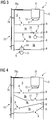
- Fig. 1-28 each a schematic diagram of a device for holding a bait according to an embodiment of the invention.
- the closing body (s) 15 do not form part (s) of the device 1 according to the invention.
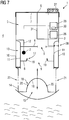
- the Fig. 1-10 each show a schematic representation of a device 1 according to an embodiment of the invention in a sectional schematic representation.
- the device 1 serves to hold a bait 2.
- the bait 2 contains substances, ie in particular poisons and active substances that cause pests to die and / or prevent pests from multiplying.
- the device 1 comprises a housing part 3.
- the housing part 3 is inserted into a sewage system 4, that is to say, for example, a sewer or sewer shaft.
- the attachment of the housing part 3 takes place via an in Fig. 1 Fastening device, not designated in more detail on the housing part, by means of which the housing part 3, in particular releasably, is fastened to a wall of the sewer system 4.
- the fastening device can comprise hook-shaped or profile-like fastening elements, so that the housing part 3 in the wall of the sewer 4 or corresponding sewer-side risers (not shown), such as. B. crampons can be attached.
- the housing part 3 is made of a corrosion-resistant material, such as. B. a steel sheet and (essentially) as a hollow cylindrical body, d. H. the housing part 3 delimits a (substantially) cylindrical receiving space 5.
- a cover member 6 may be provided in the region of an upper end face of the housing part 3.
- the housing part 3 can thus be closed on the front side by a cover element 6.
- the cover element 6 can have a threaded section (not shown) and the housing part 3 can have a threaded section (also not shown) that is the same as this, so that the cover element 6 can be screwed to the housing part 3.
- a sealing element 7 can be arranged between the cover element 6 and the housing part 3, which enables the housing part 3 to be sealed in the region of the upper end face.
- bait platform 8 is arranged or formed in the housing part-side receiving space 5.
- a plurality of, typically ring-shaped, bait platforms 8 are arranged or formed in the receiving part 5 on the housing part side.
- Respective bait platforms 8 each delimit a, typically circular, through-opening 9.
- a through-opening 9 thus defines an upper area of the receiving space 5 above it and a lower area of the receiving space 5 below it Fig. 7-10
- the respective bait platforms 8 are structurally connected to the housing part 3 via inner walls 11 which are offset radially inwards with respect to the outer wall 10 of the housing part 3.
- the bait 2 can be arranged in the upper region of the receiving space 5.
- a bait holding device 12 for holding the bait 2 is provided, on which the bait 2 is supported.
- the or another bait 2 can also be arranged lying directly on a bait platform 8.
- respective bait platforms 8 are arranged one above the other or one below the other.
- a plurality of bait platforms 8 can be arranged in parallel at least in sections (cf. in particular Fig. 2-6 ).
- An intermediate space 9a defining an intermediate level is formed between two (immediately) adjacent bait platforms 8.
- Respective interspaces 9a do not have to be the same with regard to their shape, their volume, etc., but can be designed differently. This applies to the exemplary case of more than two bait platforms 8 and thus at least two corresponding intermediate spaces 9a.
- Respective gaps 9a communicate with one another via respective through openings 9 delimited on the bait platform; There is therefore a passage possibility from a "lower” or “lowest” bait platform (up to) to an "upper” or “uppermost” bait platform.
- Corresponding bait platforms 8 or intermediate spaces 9a formed between them can cause a flow-related “calming”, generally influencing the flow, of water rising in the housing part 3.
- the water flowing into the housing part 3 and rising in it must therefore “clear” its way upward via several intermediate levels, which typically leads to a “calming” of the flow of the water.
- Respective bait platforms 8 can also be provided, at least in sections, with a flow, in particular the type of flow or the flow velocity, of surface structuring (not shown) influencing along this flowing or in the housing part 3 rising water, z. B. in the form of flow-influencing ribs and / or beads.
- through openings 9 delimited by respective bait platforms 8 can be arranged offset relative to one another.
- a through opening 9 of a first bait platform 8 can be formed in an edge region of the first bait platform 8 and a through opening 9 of a further bait platform 8 adjacent to the first bait platform 8 can be formed in an opposite edge region of the further bait platform 8.
- Due to the staggered arrangement of the respective through openings a "calming down", generally influencing the flow, of water which rises in a meandering manner in the housing part 3 is also possible.
- the offset arrangement of respective through openings 9 can also facilitate the movement of pests between the respective spaces 9a or intermediate levels.
- At least one bait platform 8 can be formed, at least in sections, with a bait platform section running inclined or bent or curved relative to at least one further bait platform section 8, which is arranged in particular adjacent.
- Corresponding inclined or curved or curved courses of the bait platforms 8 can also be used to influence the flow of water rising in the housing part 3.
- Inclined or curved or curved courses of the bait platforms 8 can also facilitate the ascent and descent of pests between the respective spaces 9a or intermediate levels in the sense of ascent or descent ramps.
- At least one bait platform 8 can be formed, at least in sections, with openings or perforations (not shown separately) that cause it.
- Respective openings of a bait platform 8, which are generally of a hole (sheet) structure, can "dampen" the flow of rising water and thus also “calm down".
- the openings are in addition to the respective through openings 9 and differ in particular in their size, i. H. in particular their diameter, from respective through openings 9; the openings are small compared to the respective through openings 9.
- Rounded openings can have a diameter of between 50 ⁇ m and 3 mm, for example.
- Fig. 6 shows an embodiment with a bait platform 8, the spiral or is formed in sections extending helically through the housing part 3.
- a pest that has penetrated into the housing part 3 can easily move within the housing part 3 via a correspondingly spiral or - similarly to a spiral staircase - helically designed bait platform 8, eg. B. to get to a bait 2.
- a spiral or helical bait platform 8 can also have an influence on the flow of water rising in the housing part 3.
- a spiral or helical bait platform 8 is also shown in dashed lines in the exemplary embodiment which shows a housing part construction comprising only one (single) bait platform 8 Fig. 1 indicated.
- a spiral or helical bait platform 8 can be expedient for a housing part construction comprising only one (single) bait platform 8, since a pest allows ascending and descending within the housing part 3 via only one (single) correspondingly spiral or helical bait platform 8 can be.
- the housing part 3 can be equipped with a closing body 15 .
- the closing body 15 is movably mounted between an open position and a closed position. The more specific task and function of the closing body 15 will be further explained in particular with reference to the exemplary embodiments according to FIGS Fig. 7-10 explained.
- Fig. 7-10 are formed between the outer wall 10 of the housing part 3 and for this purpose radially inwardly offset inner walls 11 on the housing part side guide sections 13 in the form of elongated guide receptacles.
- the guide sections 13 on the housing part side interact with corresponding guide elements 14 in the form of elongated guide webs of a closing body 15.
- the interaction of the guide sections 13 on the housing part side with the guide elements 14 on the closing body realizes a linear guide and thus a movable mounting of the closing body 15, which makes it possible to move the closing body 15 relative to the bait platform 8.
- the mounting of the closing body 15 includes a captive arrangement or connection of the closing body 15 on or with the housing part 3.
- the movable mounting of the closing body 15 enables an open position and a closed position of the closing body 15.
- the closing body 15 is therefore in particular movably supported or guided between an open position and a closed position, or can move between an open position and a closed position, and possibly vice versa, relative to the bait platform 9 are moved.
- passages 21 are formed in the guide elements on the closing body side.
- the passages 21 allow access to a lower area of the receiving space 5.
- the pest In order to reach the bait 2, the pest must also pass through the through openings 9 on the bait platform side to the upper bait platform 8 and thus to an upper area of the receiving space 5. After the bait 2 has been bitten, the pest can pass through the through openings 9 from the upper region of the receiving space 5 into the lower region of the receiving space 5 and leave the device 1 via appropriate passages 21.
- the one in the Fig. 7-10 Shown body 15 has a dome-shaped closing section 16 which, in the closed position, lies in sections sealingly against the sections 17 formed on the edges of the bait platform, which delimit the passage opening 9 delimited by the lower bait platform 8.
- the sealing contact of corresponding counter-contact sections 18 formed on the spherical closing section 16 and on corresponding contact sections 17 on the bait platform prevents water from penetrating into the upper region of the receiving space 5.
- Sealing elements 19 in the form of sealing lips are also formed on the bait platform-side contact sections 17 for the purpose of sealing.
- sealing elements 20 in the form of sealing rings are also formed on the counter-abutment sections on the closing body side.
- further sealing elements (not described in more detail) in the form of sealing lips can also be provided in the region of the opening of the guide section 13 on the housing part side and on lateral regions of the closing body 15.
- the movement of the closing body 15 from the open position into the closed position takes place in the exemplary embodiment according to FIGS Fig. 7 , 8th due to an increase in the water level in the manhole.
- This is due to the fact that the closing body 15 is designed as a floating body.
- the closing body 15 thus has z. B. an approximately air-filled cavity (not shown).
- the closing body 15 can be made from a, in particular foamed, plastic material of low density, which floats on a water surface due to the difference in density and does not sink. Movement of the closing body 15 from the open position to the closed position is therefore automatically induced by an increase in the water level in the sewer shaft. Accordingly, a movement of the closing body 15 from the closed position into the open position is induced by a drop in the water level in the sewer shaft.
- the closing body 15 can be mounted so that it can be moved in a reversible or irreversible manner, and the movement of the closing body 15 described from the open position into the closed position can thus be reversible or irreversible.
- a reversibly movable mounting of the closing body 15 means that the closing body 15 can change from the open position into the closed position on its own.
- An irreversibly movable bearing means that the closing body 15 in the closed position, in particular releasably, can be held or held by means of a closing body holding device (not shown) and therefore cannot change from the closed position to the open position on its own.
- a corresponding closing body holding device can comprise at least one mechanical and / or magnetic holding means on the housing part side and / or closing body side, which is set up to mechanically and / or magnetically hold the closing body 15 in the closed position.
- the mechanical or magnetic holding means on the housing part or closing body side can thus cooperate in such a way that the closing body 15 is securely held in the closed position and cannot be easily removed from it.
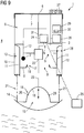
- Fig. 9 shows a further embodiment of a device 1.
- the device 1 here comprises a motor drive device 22 in the form of an electric motor which is coupled to the closing body 15 and which is set up to move the closing body 15 from the open position into the closed position and / or vice versa.
- a movement of the closing body 15 from the open position into the closing position can therefore be induced here specifically by a motor drive device 22 coupled to the closing body 15.
- the coupling between the motor drive device 22 and the closing body 15 is implemented via a traction means 23 in the form of a chain.
- the closing body 15 can also in this embodiment as Float be formed.
- the operation of the motor drive device 22 is controlled via a control device 24 assigned to it, which is set up to generate control information (control commands) that control the operation of the motor drive device 22.
- the control device 24 is also set up to generate the control information as a function of a water level information, which is supplied by a water level detection device 25 for detecting the water level in the sewer shaft receiving the device 1, or which describes a water level in the sewer shaft.
- the operation of the motorized drive device 22 can therefore be controlled as a function of the water level detected by a corresponding water level detection device 25 and mapped in a corresponding water level information in the sewer shaft receiving the device 1.
- the water level detection device 25 is arranged externally, ie spatially separated from the device 1. Accordingly, the control device 24 is also set up with the (external) water level detection device 25, for. B. radio-based to communicate.
- the control device 24 comprises a suitable receiving device and the water level detection device 25 a suitable transmitting device. In principle, however, the or a corresponding water level detection device 25 can also be integrated into the device 1.
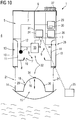
- Fig. 10 shows a further embodiment of a device 1.
- a magnetic drive device 32 is provided.
- the magnetic drive device 32 includes an electromagnetic magnetic element 33 arranged in an upper area of the receiving space 5 and a permanent magnetic magnetic element 34 arranged on the closing body side.
- the permanent magnetic magnetic element 33 on the housing part exerts such a high magnetic attraction force on the closing magnetic side permanent magnet magnetic element 34 that the closing body 15 is moved from the open position to the closed position.
- the operation of the permanent magnetic magnetic element 33 ie in particular its current flow, is equally controlled via the control device 24.
- the relevant statements in connection with the control of the operation of the motor drive device 22 apply analogously.
- the device 1 shown further comprises a closed position detection device 26 for detecting the closed position of the closing body 15.
- the closed position detection device 26 is set up to generate at least acoustic and / or optical closed position information when the closed position 15 of the closing body 15 is detected and via an output means 27. in which it is z. B. is a loudspeaker and / or an, in particular multi-colored, LED output.
- the closed position detection device 26 comprises an optical sensor system 28, implemented via an implementation of light barriers, for detecting the closed position of the closing body 15.
- the device 1 shown also includes a bite detection device 29 for detecting a bait bite.
- the bite detection device 29 is set up to generate at least acoustic and / or optical bite information when a bite 2 is bitten and to output it via the output means 27.
- the bite detection device 29 accordingly comprises a sensor system 30 for detecting a bait bite.
- the sensor system 30 can, for example, detect the weight of the bait 2 arranged on the bait holding device 12, bite-related changes in the weight of the bait 2 allowing conclusions to be drawn about a bait bite.
- the sensor system 30 can detect bite-related forces acting on the bait 2 and the bait holding device 12, which likewise allow conclusions to be drawn about a bait bite.
- the bite detection device 29 can, depending on the bite information, for. B. based on the detection of the weight of the bait 2, generate different acoustic and / or optical signals.
- the weight of a new, not bitten bait 2 can, for. B. be signaled with optical signals of green color and / or with permanently constant output optical signals
- the weight of a partially bitten bait 2 can, for. B. are signaled with optical signals of yellow color and / or with a first flashing frequency output optical signals
- the bait 2 is completely eaten, this can, for. B. be signaled by optical signals of red color and / or with an optical signal output in comparison to the first flashing frequency higher second flashing frequency.
- the output of acoustic Signals in particular the frequency and / or the rhythm of a tone or a tone sequence depending on the weight of the bait 2 or the forces acting on the bait 2 or the bait holding device 12 can be varied.
- the closed position detection device 26 and / or the bite detection device 29 is set up to communicate with the external mobile terminal and to transmit the closed position information and / or the bite information to the external mobile terminal for output at the output means there.
- the communication is, in particular, radio-based, that is to say realized via Bluetooth, WLAN, etc., which is why the closed position detection device 26 and / or the bite detection device 29 comprise corresponding radio-based transmission devices.
- Both the closed position detection device 26 and the bite detection device 29 are optional and are not absolutely necessary for the basic principle according to the invention realized by means of the device 1.
- a receiving chamber 31 is arranged in the receiving space 5, in which electrical and / or electronic components of the device 1, i. H. in particular the control device 24 and corresponding detection devices 26, 29 and possibly devices for their electrical supplies, such as. B. electrical energy storage 84 are arranged.
- the receiving chamber 31 offers protection of these components against external, i.e. H. especially climatic and mechanical influences.
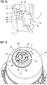
- FIG. 11 Principle representations of a device 1 according to a further exemplary embodiment are shown. Obviously it is Fig. 11 to a perspective view of the device 1, at Fig. 12 a longitudinal section through the in Fig. 11 shown device 1, at Fig. 13 for an enlarged view of the in Fig. 12 detail XIII shown, at Fig. 14 to a perspective view of the device 1 and at Fig. 15 for an enlarged view of the in Fig. 12 detail XV shown.
- the housing part 3 associated with the device 1 can also be made in several parts.
- the housing part 3 is here made of an upper housing part segment 3a and a lower housing part segment 3b.
- the housing part segments 3a, 3b can be used via unspecified ones Brackets to be attached to each other.
- other fastening principles for fastening the housing part segments 3a, 3b to one another are possible.
- the fastening device 35 On the outer circumference of the lower housing part segment 3b, in the region of the end facing away from the upper housing part segment 3a, there is also a fastening device 35 on the housing part side, by means of which the housing part 3, in particular releasably, can be fastened or fastened to a wall of the sewage system 4.
- the fastening device 35 here comprises an outer, for. B. made of steel, formed ring member 36.
- the ring member 36 can be in a Fig. 11 Attach the shown profile-like bracket 37 to the wall of a manhole.
- a ring-shaped retaining web 38 extends from the ring element 36 in the radial direction.
- the holding web 38 supports a securing element 39 fastened to the outer wall 10 of the housing part 3, ie the outer wall 10 of the lower housing part segment 3b.
- the securing element 39 which is likewise ring-shaped here, is fastened to the housing part 3, ie the outer wall 10 on the housing part side, by means of a latching mechanism.
- the latching mechanism is realized by the interaction of latching elements on the outside of the housing in the form of latching projections (not shown in more detail) and counter-latching elements on the securing element side in the form of latching recesses 66, in which the latching elements on the outside of the housing can latch.
- latching elements on the outside of the housing in the form of latching projections (not shown in more detail)
- counter-latching elements on the securing element side in the form of latching recesses 66 in which the latching elements on the outside of the housing can latch.
- an inverted arrangement is also conceivable, ie latching elements on the outside of the housing wall in the form of latching recesses and latching elements on the securing element side in the form of latching projections.
- a region of the ring element 36 formed below the holding web 38 serves in the closed position of an optional closing body 15 as a contact surface for a sealing element which is arranged or formed on the outer circumferential side of the closing body 15 and is not designated in any more detail.
- the securing element 39 is used for the captive arrangement of a closing body 15 on the housing part 3. This is realized in that an extension 40 on the securing element side, here angled, is inserted into the guide sections 13 formed between the outer wall 10 on the housing part side and the inner wall part 11 offset radially inward for this purpose engages that the closing body 15 is prevented from sliding out of the guide section 13 due to an extension 41 projecting radially from the upper section of the guide elements 14 on the closing body side.
- Fig. 12 It can be seen that the surfaces 42 extending from the closing section 16 of the closing body 15 are slightly inclined, that is to say, for example by 3 to 5 °, so that water on the closing body 15 can flow radially outwards.
- the receiving chamber 31 has a receiving chamber base body 44 which defines a cylindrical, receiving chamber volume 43 for receiving electrical and / or electronic components of the device 1. Obviously, the receiving chamber base body 44 projects in sections into the receiving space 5.
- a bait holding device 12 for holding a bait 2 is arranged on a lower section of the receiving chamber base body 44 projecting into the receiving space 5.
- the receiving chamber 31 can be detachably attached to the housing part 3, ie here the upper housing part segment 3a.
- the releasable fastening of the receiving chamber 31 to the housing part 3 can be formed or formed by positive engagement of fastening parts 45 on the housing part side with fastening sections 46 on the housing body side.
- the receiving chamber 31 and the housing part 3 are thus each equipped with fastening sections 45, 46, the interaction of which enables a stable or captive, yet detachable fastening of the receiving chamber 31 to the housing part 3.
- a form-fitting interaction of respective fastening sections 45, 46 is to be understood as meaning at least section-wise interlocking or overlapping of corresponding fastening sections 45, 46.
- the receiving chamber 31 is rotatably arranged on the housing part 3 between a fastening position and a release position.
- the fastening position the fastening sections 45 on the housing part side and the fastening sections 46 on the receiving chamber base body side cooperate in a form-fitting manner, so that the receiving chamber 31 is detachably fastened to the housing part 3.
- the release position the fastening sections 45 on the housing part side and the fastening sections 46 on the receiving chamber base body side do not cooperate, so that the receiving chamber 31 can be detached from the housing part 3.
- the attachment of the receiving chamber 31 to the housing part 3 can thus be produced and canceled again by rotating movements of the receiving chamber 31 about an axis of rotation, which typically coincides with the symmetry or central axis of the receiving chamber 31.
- the receiving chamber 31 can thus be transferred from the fastening position into the release position and vice versa by rotary movements relative to the housing part 3.
- the housing part-side fastening sections 45 are radially inward as one of an axially aligned cylindrical section 47 of the housing part 3 projecting ring segment disc element 48 is formed with at least one axially projecting shoulder-like fastening projection 49.
- the mounting sections 46 on the main body side of the receiving body are designed as an annular segment disc element 51 projecting radially outward from a cylindrical extension 50 of the main receiving body body 44 with a mounting projection 49 corresponding to the mounting projection 49 formed on the mounting part 45 on the housing part side, that is to say configured or aligned axially projecting shoulder-like mounting projection 52.
- the receiving chamber 31 has a tool engagement area 54 in the area of an upper exposed cover section 53, in which a tool 55, which is T-shaped here, can engage in a form-fitting manner with an engagement section 57 (cf. in particular Fig. 14 ).
- a tool 55 which is T-shaped here
- an engagement section 57 (cf. in particular Fig. 14 ).
- rotary movements can be transmitted to the receiving chamber 31 in order to transfer the receiving chamber 31 from the fastening position into the release position and vice versa.
- the tool engagement area 54 is designed here with ring-segment-shaped tool receptacles 58, into which the cross-sectionally rounded tool-side engagement section 57 can engage, so that rotational movements of the tool 55 counterclockwise lead to rotational movements of the receiving chamber 31 counterclockwise.
- a stop section 59 is arranged circumferentially opposite the engagement section 57. Between the engagement section 58 and the stop section 59, a circumferentially extending gap 60 is formed, via which the tool 55 can be inserted into the tool engagement area 54 in order to cooperate accordingly.
- the tool engagement area 54 is always accessible (from above) due to the arrangement or design of the tool engagement area 54 in the area of an upper exposed cover section 53 of the receiving chamber 31.
- the geometric shape of the tool engagement area 54 is adapted to the shape of the tool 55.
- the geometrical shape of the tool engagement area 54 is such that a T-shaped tool 55 can engage it in a form-fitting manner, so that rotary movements of the tool 55 indicated by the double arrow 56 can be transmitted to the receiving chamber 31.
- the tool engagement area 54 is easily accessible, ie in particular from above. It is not by suitable shaping and dimensioning of a corresponding tool 55 absolutely necessary for a user to descend into the sewer shaft in order to transfer the receiving chamber 31 from the fastening position into the release position or vice versa by means of corresponding rotary movements.
- the receiving chamber 31 can thus be detached from the housing part 3 from outside the duct shaft and in particular removed from the duct shaft. This can be for control purposes, e.g. B. whether a bait bite has occurred, be practicable, so that controls can be carried out considerably simplified and carried out much faster.
- the receiving chamber 31 together with the bait holding device 12 and bait 2 held thereon can be removed from the sewer shaft without having to enter the sewer shaft, any bait bite recognized, possibly an exchange or replacement of the or of a bait 2 and the receiving chamber 31 together with the bait holding device 12 and bait 2 held thereon are brought back into the sewer shaft.
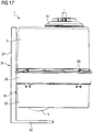
- FIG. 16 shows a pure schematic representation of the device 1
- Fig. 17 2 shows a perspective view of the device 1
- Fig. 18 a longitudinal section through the in Fig. 17 shown representation
- Fig. 19 an enlarged view of the in Fig. 18 detail shown XIX.
- the embodiment according to the Figures 16-19 additionally includes a surge protection element 61 for protecting the penetration of water into the receiving space 5 delimited by the housing part 3, in particular in an upper region of the receiving space 5 lying above the passage opening 9 delimited by the lower or lower bait platform 8, in the event of a surge or suddenly rising water level in the sewer shaft, in which the housing part 3 is to be used.
- a surge protection element 61 for protecting the penetration of water into the receiving space 5 delimited by the housing part 3, in particular in an upper region of the receiving space 5 lying above the passage opening 9 delimited by the lower or lower bait platform 8, in the event of a surge or suddenly rising water level in the sewer shaft, in which the housing part 3 is to be used.
- the surge protection element 61 is arranged below the lower or lowest bait platform 8.
- the surge protection element 61 has an annular or cylindrical base body 62, which delimits a water surge receiving volume 63 for receiving a certain amount of water flowing in the or a manhole.
- A e.g. B. caused by heavy rain, surge-like sudden rise in the water level in the manhole leads to the fact that the water first penetrates from below into the flood surge volume 63 and fills it.
- the purely optional closing body 15 designed here as a floating body, as mentioned, is inside the base body 62 of the surge protection element 61, ie inside the Water surge intake volume 63, movably mounted, such that it increases in the case of an increase in the water level in the water surge intake volume 63 associated with the entry of water into the water surge intake volume 63 Fig. 16 , 17th shown in the open position in Fig. 16 dashed indicated closed position is moved.
- the movable mounting of the closing body 15 is realized via a bracket 64 on the housing part side, here in the form of an angled gallows bracket.
- the closing body 15 with a closing section 16 lies in sections sealingly against the contact sections 17 formed by the edges of the lower or lower bait platform 8, which delimit through opening 9 delimited by the lower or lower bait platform 8.
- the sealing contact of the closing body 15 with corresponding contact sections 17 on the bait platform prevents water from penetrating into the upper region of the receiving space 5 on the housing part side. There is no possibility that water will get into the upper area of the receiving space 5 and be contaminated there by the substances contained in the bait 2.
- the base body 62 of the surge protection element 61 is open here, i. H. shown without floor space.
- the base body 62 of the surge protection element 61 in the region of its side facing away from the lower or lowermost bait platform 8 to comprise a bottom surface which has at least one surge water inlet opening.
- a closing body 15 can then be arranged at least in sections in the splash water inlet opening in the open position. When the water level rises, a closing body 15 designed as a floating body lifts up from the splash water inlet opening, so that water can enter the flooding volume 63 until the closing body 15 is finally moved from the open position into the closed position, as described.
- the base body 62 of the surge protection element 61 in the exemplary embodiment according to FIG Fig. 16 a number of, e.g. B. web-like, feet 65, which serve to support the base body 62, optionally also the housing part 3 arranged thereon, in addition to the components of the device 1 arranged or fastened therein.
- the base body 62 can also be designed to be completely flat on the bottom or front side and thus corresponding feet 65 can be dispensed with.
- the device 1 can be fastened to the wall of a manhole via a fastening device 35.
- the fastening device 35 comprises an outer, for. B. made of steel, ring element 36.
- the ring element 36 can be fastened to the wall of a duct shaft via a profile-like holder 37.
- the embodiment shown does not have corresponding feet 65 on the part of the surge protection element 61.
- the profile-like holder 37 is of elongated design and comprises a bearing leg 67 protruding from it at an angle, in particular perpendicular, which can be referred to or regarded as the base of the device 1.
- the surge protection element 61 is fastened to the housing part 3 here by screw connections.
- both the surge protection element 61 and the housing part 3, here in each case on the outer peripheral side, are provided with screw receptacles 68, which can be penetrated by screw-like connecting elements, in particular threaded screws, which are not shown in any more detail.
- screw-like connecting elements in particular threaded screws
- FIG. 18 The sectional view shown shows that the ring element 36 is arranged between the surge protection element 61 and the housing part 3. Based on the in Fig. 19 The detail shown can be seen that the surge protection element 61 is provided for this purpose with corresponding radially protruding annular holding webs 69 which form a bearing point for the ring element 36.
- the housing part 3 is provided in the region of its free end facing the surge protection element 61 with a radial extension 70, into which the ring element 36 engages with the region of its end facing the housing part 3.
- a sealing element 71 here in the form of a sealing ring, is arranged or formed between the housing part 3 and the ring element 36.
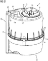
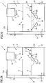
- FIG. 20 Principle representations of a device 1 according to further exemplary embodiments are shown. Obviously it is Fig. 20 , 21st in each case a perspective view of a further exemplary embodiment of a device 1, in Fig. 22 a longitudinal section through the in Fig. 20 shown device 1 and at Fig. 23 to a cross section through the in Fig. 22 shown device 1.
- FIG. 3 shows a mounting of a closing body 15, as mentioned, which is movable relative to the lower bait platform 8 by means of a clamp-like or clip-like holding element 72 mounted on the lower bait platform 8, in particular pivotably.
- the holding element 72 which can also be referred to as a holding clip or holding clip, is fastened to the closing body 15 on the one hand, in particular at one end, of the lower bait platform 8 and on the other hand, in particular at the other end.
- connection of the closing body 15 to the holding element 72 Via the connection of the closing body 15 to the holding element 72, the connection of the holding element 72 to the lower bait platform 8 as well as the geometric dimensions, ie in particular the shape, of the holding element 72 defines a specific movement path through which the closing body 15 travels during a movement from the open position to the closed position and vice versa.
- the holding element 72 comprises two holding element sections 72a, 72b which run at an angle to one another. Based on Fig. 22 It can be seen that the holding element sections 72a, 72b engage in the open position of the closing body 15 through the passage opening 9 delimited on the bait platform side.
- the holding element sections 72a, 72b are bent in an L-shape.
- the holding element 72 thus has an (essentially) L-shaped geometric shape.
- a particularly expedient fastening device 73 is also shown, by means of which the housing part 3 can be fastened, in particular releasably, to a wall of a sewer system 4, in particular a sewer shaft.
- the fastening device 73 comprises an annular, first fastening element 74 which surrounds the housing part 3 on the outer circumference and is fastened to the housing part 3 via fastening clips 76 screwed to the housing part 3, and a second fastening element 75 for fastening the first fastening element 74 and the housing part 3 fastened thereon on the wall of a sewer 4 or a manhole.
- the fastening device 73 enables stable fastening of the housing part 3 to a wall of a sewer system 4 or a duct shaft, in particular with regard to flooding or splash water-related forces acting on the housing part 3.
- the second fastening element 75 is fastened to the wall of a sewage system 4 or a sewer shaft by means of fastening bolts 78 or - starting from the second fastening element 75 or on the part of the second fastening element 75, optionally provided with a thread, passing through horizontal or vertical bores 77. screws realized, which, for. B. by walls or screws, are stably anchored in the wall of a sewer 4 or a manhole.
- the fastening device 73 is made in several parts.
- the second fastening element 75 comprises a fastening element section 75a that extends over the upper side of the housing part 3 to form a buoyancy protection.
- the housing part 3 is protected against buoyancy forces caused by flooding or splashing water, and in its, in particular vertical, positioning is fixed in position on the sewage system 4.
- All components of the fastening device 73 are made of one or more mechanically and corrosion-resistant materials, for. B. stainless steels or material structures formed or include such materials or material structures.
- a plurality of fastening element sections 75a can be present.
- Fastening element sections 75a shown are releasably attached to the exposed upper side of the housing part 3 in a form-fitting manner (without damage or destruction).
- the fastening is thus carried out by a form fit, that is to say via the form-fitting interaction of form-fitting elements 79 on the part of the fastening element sections 75a with corresponding form-fitting elements 80 on the part of the housing part 3.
- Form-fitting elements 79 formed on respective fastening element sections 75a are designed as an opening, on the housing part 3 there are form-fitting elements 80 formed by, in particular vertical, projections which engage in or through corresponding openings in the fastened state.
- respective fastening element sections 75a can be designed with, in particular cross-section-reducing, stiffening structures 81 to increase the mechanical stability of the fastening element sections 75a. In this way, the material thickness and thus the weight of the fastening device 73 can be reduced without sacrificing mechanical stability.
- the respective fastening element sections 75a are in the exemplary embodiments according to FIGS Figures 20-23 formed as separate components and releasably attached to a profile-like base body of the second fastening element 75 by means of screw bolts 82, ie a screw fastening (without damage or destruction).
- the fastening element sections 75a could also be formed in one piece with the second fastening element 75.
- FIG. 22 An optional monitoring device 83 for monitoring at least a part of the receiving space 5 delimited by the housing part 3 is shown.
- the monitoring device 83 is arranged on the receiving chamber 31 in such a way that the receiving space 5 can be monitored as widely as possible.
- the monitoring device 83 comprises a suitable optical sensor system for monitoring the Recording room 5.
- the monitoring device 83 is in the embodiment according to Fig. 22 designed as an infrared sensor or camera.
- rodent-related processes can be quantitatively and / or qualitatively recorded and evaluated or assessed.
- Processes of particular interest that are to be monitored quantitatively and / or qualitatively are, for example, the entry of rodents into the receiving space 5, the exit of rodents from the receiving space 5, the behavior, ie. H. in particular the biting and / or movement behavior, rodents entering the recording room 5 in the recording room 5 etc.
- the frequency of the recording room 5 can be recorded and evaluated or evaluated quantitatively and / or qualitatively per specific unit of time.
- monitoring information or data recorded by the monitoring device 83 can of course be transmitted to a user-specific, in particular mobile, external terminal 92 via a suitable communication device 91, in particular radio-based communication connection, "monitoring" can be carried out via a corresponding monitoring device 83 Realize all processes in the receiving space 5 without the need to enter the sewer shaft equipped with the device 1 or into the sewer system 4 equipped with the device 1.
- the communication is expediently radio-based, i. H. e.g. B. realized by Bluetooth, WLAN, etc., which is why the monitoring device 83 comprises a corresponding radio-based transmission device (not shown) or is connected to such.
- the monitoring device 83 is supplied with electrical energy via a rechargeable electrical energy store 84 arranged in the receiving chamber 31.
- the energy store 84 is an electrochemical energy store in the form of a rechargeable battery. It would also be conceivable to use an inductive, i.e. H. an energy storage device that can be recharged by means of electromagnetic induction.
- the surface structuring 85 makes it easier for a rodent to access the lower bait platform 8 via the closing body 15.
- the surface structuring 85 is formed by a step-like or rib-like structure of the circular disc-shaped section of the spherical segment-shaped closing body 15 and offers a hold or a rodent entering the closing body 15. Liability.
- the surface structuring 85 inhibits or accordingly prevents the Rodent from the closing body 15 and thus serves in the sense of an "entry aid" for access to the lower bait platform 8.
- a corresponding surface structure 85 also serves a rodent vice versa in the sense of an "exit aid” for leaving the lower bait platform 8.
- annular section 86 which also serves in the sense of a corresponding “entry aid” or “exit aid”.
- Fig. 22 Also shown is a region 87 for a bait 2 which is delimited by a wall 88 projecting from the lower bait platform 8 at an angle, in particular vertically, here.
- the embodiment according to Fig. 22 shows a special storage of a corresponding energy store 84.
- the energy store 84 is mounted on a base plate 94 (detachably) fastened to a bottom section 93 of the receiving chamber 31 which projects into the receiving space 5.
- the base plate 94 is attached to the base portion 93 by means of attachment screws (not shown) (cf. Fig. 23 ).
- a sealing element 96 in the form of a sealing ring between the bottom plate 94 and the bottom section 93.
- a further sealing element is located between the receiving chamber 31 and the housing part 3.
- the base plate 94 is provided with angled, in particular vertical, projecting walls 95 which delimit a receiving area for the energy store 84.
- the energy store 84 can typically be arranged with a precise fit in the receiving area.
- the base plate 94 together with the energy store 84 arranged on it can be regarded as a separate assembly that can be fastened to the receiving chamber 31. B. in the context of an exchange or recharging of the energy storage 84, can be easily detached from the receiving chamber 31 and reattached to it.
- the monitoring device 83 and the communication device 91 are arranged on the bottom section 93 to the side of the energy store 84.
- An opening 95 is provided on the floor section side for the monitoring device 83.
- a corresponding flap device 89 in the exemplary embodiment according to FIG Fig. 24 a flap element 90 which is movable, in particular pivotable, mounted relative to a lower bait platform 8, which is moved away from the lower bait platform 8 in an open position such that the passage opening 9 on the bait platform side is released, and in a closed position shown in broken lines is moved against the bait platform 8 that the passage opening 9 limited on the bait platform side is closed.
- the closing body 15 can be an integral part of the flap device 89. It is also possible to attach a separate closing body 15 to a corresponding flap element 90.
- the closing body 15 can be designed as a floating body or comprise at least one floating body.
- a corresponding flap device 89 can comprise a plurality of flap elements 90 which, in a respective open position, are moved away from a lower bait platform 8 in such a way that the passage opening 9 on the bait platform side is exposed, and in a respective closed position shown in dashed lines against the bait platform 8 are moved that the passage opening 9 limited on the bait platform side is jointly closed by the flap elements 90.
- respective closing bodies 15 are arranged on respective flap elements 90.
- the exemplary embodiments shown show the possibility of a, in particular linear, movable guidance of the housing part 3 inserted into a duct shaft 96 along or relative to a wall of the duct shaft 96.
- the housing part 3 is therefore not fastened here via a corresponding fastening device 35, 73, but is guided by means of a guide device 97, in particular linearly, movably along or relative to a wall of the duct shaft 96.
- a guide device 97 therefore makes it possible for the housing part 3 inserted into the duct shaft 96 to move within the duct shaft 96 along with and / or components of the device 1 arranged therein, in particular in a linearly movable manner.
- Movements of the housing part 3 take place along a vertical axis of movement indicated by the vertically aligned double arrow, ie, for example, along a symmetry or central axis of the duct shaft 96.
- the housing part 3 is guided in a secured, moveable manner against tilting in the duct shaft 96; the guide device 97 thus prevents the housing part 3 from tilting in the duct shaft 96.
- a guide device 97 which comprises a plurality of wheel-like or roller-like guide elements 98 which are distributed on or around the housing part 3 and via which the housing part 3 is guided in a rolling manner along the wall of the duct shaft 96 on the wall of the duct shaft 96.
- Corresponding wheel-like or roller-like guide elements 98 lie directly on the wall of the duct shaft 96, so no special precautions for implementation are provided on the wall side the movable guide of the housing part 3 are necessary.
- the wheel-like or roller-like guide elements 98 are specifically wheels or rollers.
- the wheel-like or roller-like guide elements 98 are mounted on a holding device 99 arranged or formed on the housing part 3.
- the wheel- or roller-like guide elements 98 are clamped against the wall of the duct shaft 96 via the holding device 99.
- Such a mounting and bracing enables a secure vertical positioning of the housing part 3 in the duct shaft 96.
- the clamping force is selected so that an uncontrolled sinking of the housing part 3 prevents vertical movements of the housing part 3, e.g. B. caused by surge water-induced buoyancy forces, in particular in the direction of a manhole cover 100 or in the direction of an upper manhole opening, are nevertheless made possible.
- the holding device 99 comprises holding arms 101 which are mounted on the housing part 3 such that they can be swiveled or pivoted and can be swiveled or pivoted against the wall of the duct shaft 96.
- the holding arms 101 are with a clamping element 102, in particular a spring element, for. B. in the form of a compression spring coupled.
- a tensioning force, in particular spring force, tensioning the guide elements 98 against the wall of the duct shaft 96 is exerted on the holding arms 101 via the tensioning elements 102 arranged between the housing part 3 and the respective holding arms 101.
- the housing part 3 can be inserted into a multiplicity of duct shafts 96 with different diameters and (angularly) braced against the duct shaft walls.
- a holding device 99 is shown in dashed lines, which comprises, in particular telescopically, extendable holding arms 101 which can be extended radially (with respect to the symmetry or central axis of the housing part 3 or the duct shaft 96) against the walls of the duct shaft 96 (cf. the horizontal double arrow) .
- This holding arms 101 can in an analogous manner with corresponding clamping elements 102, in particular spring elements, for. B. in the form of compression springs.
- a guide device 97 which comprises a gear-like linear guide element 103 on the housing part side and a rack-like linear guide element 104 on the wall side corresponding or interacting with it.
- the housing part 3 is guided in a linearly movable manner on the wall of the duct shaft 96 via the guide device 97.
- the guide device 97 also includes wall-side guide elements in the form of corresponding rack-like linear guide elements 104.
- the housing part-side and wall-side linear guide elements 103, 104 are in a mechanical Intervention or a mechanical operative connection, ie they work together to form a corresponding linear guide.
- the respective guide devices 97 can comprise a drive device (not shown) that can be coupled or coupled to at least one guide element 98 or linear guide element 103, 104 and is configured to drive the guide elements 98 or linear guide elements 103 , 104 to transmit a unidirectional or bidirectional drive movement to the guide elements 98 or linear guide elements 103, 104.
- a drive device can be arranged or formed on or in the housing part 3.
- a corresponding drive device can also be arranged or formed on or in a corresponding guide element 98 or linear guide element 103, 104, ie, for example, integrated in a wheel or roller-like guide element 98 or in a gearwheel.
- a corresponding drive device can be an electric motor, the energy supply of which is analogous to the energy supply of other electrical or electronic components of the device 1.
- a guide device 97 can also comprise a profile-like or rod-like guide element 105 which is fastened in the duct shaft 96 and arranged on the housing part 3 or which, in particular axially, penetrates it.
- the housing part 3 is here also guided in a linearly movable manner relative to the profiled rod-like guide element 105.
- This also includes fastening the housing part 3 to the profile-rod-like guide element 105, which in turn is fastened on the duct shaft side, that is, for example, walled in, screwed, etc.
- the profile-like or rod-like guide element 105 in the exemplary embodiment does not lie directly against a duct shaft wall, but is arranged concentrically within the duct shaft 96.
- Such a profile or rod-like guide element 105 can in particular also in the embodiment according to Fig. 26 be useful, which is why it is dashed there, because optional, is also shown.
- floating bodies 106 can be present in the duct shaft 96 in order to implement or support movements of the housing part 3.
- the positioning of the floating bodies 106 on the housing part 3 is shown above an optional closing body 15 shown because it is located within the housing part 3, so that water rising in the duct shaft 96 only reaches the floating bodies 106 on the housing part side when the closing body 15 is already in the closed position .
- the housing part 3 can already be formed with integrated floating bodies 106. This can be done constructively e.g. B. be realized by at least one cavity defining or having housing part wall. The cavity is filled with air, for example. It is also conceivable to manufacture a housing part wall from a material of low density, which floats on a water surface due to the difference in density and does not sink. In all cases, an upward movement of the housing part 3 is induced by an increase in the water level in the sewer shaft 96 and a downward movement of the housing part 3 by a decrease in the water level in the sewer shaft 96.
- the housing part 3 can be provided with stiffening structures to increase the mechanical stability of the housing part 3.
- Corresponding stiffening structures can, for. B. ring or rib-like.
- Corresponding stiffening structures can be present as separate components which are to be correspondingly attached to the housing part 3 or connected to it, or can be formed integrally with the housing part 3.
Landscapes
- Life Sciences & Earth Sciences (AREA)
- Insects & Arthropods (AREA)
- Pest Control & Pesticides (AREA)
- General Health & Medical Sciences (AREA)
- Toxicology (AREA)
- Engineering & Computer Science (AREA)
- Health & Medical Sciences (AREA)
- Wood Science & Technology (AREA)
- Zoology (AREA)
- Environmental Sciences (AREA)
- Catching Or Destruction (AREA)
- Sewage (AREA)
- Feeding And Watering For Cattle Raising And Animal Husbandry (AREA)
Priority Applications (5)
| Application Number | Priority Date | Filing Date | Title |
|---|---|---|---|
| DE502015012661.2A DE502015012661C5 (de) | 2015-01-19 | 2015-02-18 | Vorrichtung zur halterung eines köders, insbesondere eines köders für nagetiere |
| EP20176530.2A EP3718401B1 (de) | 2015-01-19 | 2015-02-18 | Vorrichtung zur halterung eines köders, insbesondere eines köders für nagetiere |
| EP24178400.8A EP4417051A3 (de) | 2015-01-19 | 2015-02-18 | Vorrichtung zur halterung eines köders, insbesondere eines köders für nagetiere |
| PL15720580T PL3247208T3 (pl) | 2015-01-19 | 2015-02-18 | Urządzenie do podtrzymywania przynęty, w szczególności przynęty na gryzonie |
| SI201531318T SI3247208T1 (sl) | 2015-01-19 | 2015-02-18 | Naprava za držanje vabe, zlasti vabe za glodalce |
Applications Claiming Priority (2)
| Application Number | Priority Date | Filing Date | Title |
|---|---|---|---|
| DE102015000348.8A DE102015000348A1 (de) | 2015-01-19 | 2015-01-19 | Vorrichtung zur Halterung eines Köders |
| PCT/DE2015/000073 WO2016116079A1 (de) | 2015-01-19 | 2015-02-18 | Vorrichtung zur halterung eines köders, insbesondere eines köders für nagetiere |
Related Child Applications (2)
| Application Number | Title | Priority Date | Filing Date |
|---|---|---|---|
| EP24178400.8A Division EP4417051A3 (de) | 2015-01-19 | 2015-02-18 | Vorrichtung zur halterung eines köders, insbesondere eines köders für nagetiere |
| EP20176530.2A Division EP3718401B1 (de) | 2015-01-19 | 2015-02-18 | Vorrichtung zur halterung eines köders, insbesondere eines köders für nagetiere |
Publications (2)
| Publication Number | Publication Date |
|---|---|
| EP3247208A1 EP3247208A1 (de) | 2017-11-29 |
| EP3247208B1 true EP3247208B1 (de) | 2020-05-27 |
Family
ID=53052632
Family Applications (3)
| Application Number | Title | Priority Date | Filing Date |
|---|---|---|---|
| EP15720580.8A Active EP3247208B1 (de) | 2015-01-19 | 2015-02-18 | Vorrichtung zur halterung eines köders, insbesondere eines köders für nagetiere |
| EP20176530.2A Active EP3718401B1 (de) | 2015-01-19 | 2015-02-18 | Vorrichtung zur halterung eines köders, insbesondere eines köders für nagetiere |
| EP24178400.8A Pending EP4417051A3 (de) | 2015-01-19 | 2015-02-18 | Vorrichtung zur halterung eines köders, insbesondere eines köders für nagetiere |
Family Applications After (2)
| Application Number | Title | Priority Date | Filing Date |
|---|---|---|---|
| EP20176530.2A Active EP3718401B1 (de) | 2015-01-19 | 2015-02-18 | Vorrichtung zur halterung eines köders, insbesondere eines köders für nagetiere |
| EP24178400.8A Pending EP4417051A3 (de) | 2015-01-19 | 2015-02-18 | Vorrichtung zur halterung eines köders, insbesondere eines köders für nagetiere |
Country Status (15)
| Country | Link |
|---|---|
| US (1) | US10869470B2 (da) |
| EP (3) | EP3247208B1 (da) |
| CN (1) | CN107567277B (da) |
| AU (1) | AU2015378125B2 (da) |
| CA (1) | CA2973503C (da) |
| DE (3) | DE102015000348A1 (da) |
| DK (1) | DK3247208T3 (da) |
| ES (2) | ES2813427T3 (da) |
| HU (1) | HUE050639T2 (da) |
| NZ (1) | NZ734496A (da) |
| PL (1) | PL3247208T3 (da) |
| PT (1) | PT3247208T (da) |
| RU (1) | RU2671105C1 (da) |
| SI (1) | SI3247208T1 (da) |
| WO (1) | WO2016116079A1 (da) |
Families Citing this family (9)
| Publication number | Priority date | Publication date | Assignee | Title |
|---|---|---|---|---|
| GB2521399B (en) * | 2013-12-18 | 2016-11-16 | Rentokil Initial Plc | Bait station for pest control |
| DE102014112804B4 (de) * | 2014-09-05 | 2016-04-28 | Wolfgang Bittlinger | Vorrichtung zur Halterung eines Köders, insbesondere eines Köders für Nagetiere |
| DE102016107226A1 (de) | 2016-04-19 | 2017-10-19 | Michalski Saemann Spering GbR (vertretungsberechtigter Gesellschafter: Axel Spering, 52076 Aachen) | Köderbox und Verfahren zum Trennen einer Fressstelle |
| DE102016109930A1 (de) * | 2016-05-30 | 2017-11-30 | Jürgen Buchstaller | Vorrichtung zur Halterung eines Köders |
| CN107747963A (zh) * | 2017-11-02 | 2018-03-02 | 河海大学 | 白蚁诱饵站自动监测报警系统 |
| FR3092966B1 (fr) * | 2019-02-21 | 2021-07-16 | Sas Ratdar | Module d’application de produits rodenticides et système correspondant |
| WO2022073056A1 (en) * | 2020-10-07 | 2022-04-14 | Pestsense Holdings Pty Limited | Bait station |
| US12564185B2 (en) | 2023-02-03 | 2026-03-03 | SIS Development, Inc. | Automatic optimizing pest control substance delivery system |
| CN117256578A (zh) * | 2023-09-20 | 2023-12-22 | 重庆清道夫环保服务有限公司 | 一种白蚁诱杀报警装置 |
Citations (1)
| Publication number | Priority date | Publication date | Assignee | Title |
|---|---|---|---|---|
| WO2015124137A1 (de) * | 2014-02-18 | 2015-08-27 | Wolfgang Bittlinger | Vorrichtung zur hälterung eines köders, insbesondere eines köders für nagetiere |
Family Cites Families (45)
| Publication number | Priority date | Publication date | Assignee | Title |
|---|---|---|---|---|
| US1119502A (en) * | 1914-01-22 | 1914-12-01 | George W Evans | Insect-destroyer. |
| US2340255A (en) * | 1942-01-27 | 1944-01-25 | Weil Alex | Roach run |
| US2429377A (en) * | 1944-01-24 | 1947-10-21 | John L Stevens | Flytrap |
| DE928497C (de) * | 1953-12-22 | 1955-06-02 | Ewald Droszella | Traeger fuer Giftkoeder, vorzugsweise in Kanalisationsanlagen |
| US2772511A (en) * | 1955-04-19 | 1956-12-04 | Pittsburgh Coke & Chemical Co | Device for killing insects |
| US2860445A (en) * | 1955-11-04 | 1958-11-18 | Yates Hershel | Rodent exterminating device |
| US3517454A (en) * | 1967-08-17 | 1970-06-30 | Grady W Query | Feeder and package arrangement for fluent dry solids |
| US4035946A (en) * | 1975-11-24 | 1977-07-19 | Wallace Thomas Rapp | Trap for slugs and snails |
| US4400904A (en) * | 1981-07-27 | 1983-08-30 | Baker Rex O | Rodent bait station |
| FR2516747A1 (fr) * | 1981-11-23 | 1983-05-27 | Couloigner Rene | Radeau porteur d'appats pour rats musques (ondatra zibethicus) |
| US4521987A (en) * | 1983-10-11 | 1985-06-11 | Knote Charles E | Bait station and trap |
| US4550525A (en) * | 1984-08-22 | 1985-11-05 | J. T. Eaton & Company, Inc. | Tamper proof rodent bait station |
| GB2230930A (en) * | 1989-05-03 | 1990-11-07 | Anthony Vincent | Weight-activated animal traps |
| US6151828A (en) * | 1991-07-10 | 2000-11-28 | Genero; Claude Paul | Insect feeding station |
| DE19515454A1 (de) * | 1994-05-27 | 1995-11-30 | Theysohn Friedrich Fa | Vorrichtung zum Bekämpfen von fliegenden Forstschädlingen |
| DE19526043A1 (de) * | 1995-07-17 | 1997-01-23 | Hans Ettrich | Durchfallschleuse zum Begiften und nachträglichem Freilassen von Schadinsekten |
| US5693331A (en) * | 1996-03-25 | 1997-12-02 | Fmc Corporation | Liquid bait station |
| US6182482B1 (en) * | 1997-11-18 | 2001-02-06 | Aegis Research | Tamper proof lock assembly and key |
| US5918409A (en) * | 1998-06-15 | 1999-07-06 | Carnwath; James R. | Self clearing tunnel rat trap |
| US6016623A (en) * | 1998-10-08 | 2000-01-25 | Celestine; Wallace | Rodent trap |
| US7026942B2 (en) * | 1999-06-08 | 2006-04-11 | Gilberto Cristofori | Method for signalling the presence of prey in traps for vermin and device for carrying out this method |
| US6651378B2 (en) * | 2000-05-16 | 2003-11-25 | Stanley Z. Baker | Bait station for insects |
| IE20020359A1 (en) * | 2001-05-30 | 2002-12-11 | Raymond Joseph Walsh | Vermin extermination |
| US6571509B2 (en) * | 2001-06-01 | 2003-06-03 | Kenneth L. Frasier | Rodent poison feeder |
| DE60202467T2 (de) * | 2001-06-16 | 2006-02-16 | Reckitt Benckiser Inc. | Köderstation für nagetiere |
| US20040128903A1 (en) * | 2003-01-08 | 2004-07-08 | Kenneth Wexler | Mosquito barrier for drainage structure |
| DE20303592U1 (de) * | 2003-03-05 | 2003-06-05 | Klass, Michael, 63452 Hanau | Rattenfalle |
| US6966500B1 (en) * | 2004-04-12 | 2005-11-22 | Kelley Richard D | Remote controlled scent dispensing device |
| EP1638767B1 (en) * | 2004-05-11 | 2008-01-16 | S.C.Johnson & Son, Inc | Bait stations |
| US20060032110A1 (en) * | 2004-08-16 | 2006-02-16 | Keng-Ming Yang | Trapping device |
| US7377072B2 (en) * | 2005-05-31 | 2008-05-27 | S.C. Johnson & Son, Inc. | Bait station |
| US20080083375A1 (en) * | 2006-09-25 | 2008-04-10 | Stepanian Aram A | Bird feeder with squirrel protection |
| US20090020073A1 (en) * | 2007-07-16 | 2009-01-22 | Hansen Daniel D | Deer conditioning system |
| GB0721244D0 (en) * | 2007-10-30 | 2007-12-05 | Killgerm Group Ltd | Bait station |
| US9015987B2 (en) * | 2007-12-27 | 2015-04-28 | New Frequency, Inc. | Telemetry-enabled trap monitoring system |
| HUE026990T2 (en) * | 2008-02-06 | 2016-08-29 | Wisecon As | rat Trap |
| US8336251B2 (en) * | 2008-02-14 | 2012-12-25 | Orchard Stanley A | Trapping system utilizing video attractants |
| RU95224U1 (ru) * | 2010-02-17 | 2010-06-27 | Федеральное государственное образовательное учреждение высшего профессионального образования "Тюменская государственная сельскохозяйственная академия" | Устройство для дератизации |
| US8782947B2 (en) * | 2010-11-02 | 2014-07-22 | Ernest H. Roberts | Assured snap enclosure apparatus and improvement |
| US20140059919A1 (en) * | 2012-09-04 | 2014-03-06 | Joseph C. Pupello | Rodent bait station |
| DE102014102034B4 (de) * | 2014-02-18 | 2016-04-28 | Wolfgang Bittlinger | Vorrichtung zur Halterung eines Köders, insbesondere eines Köders für Nagetiere |
| DE102015105596A1 (de) * | 2015-04-13 | 2016-10-13 | Jürgen Buchstaller | Vorrichtung zur Halterung eines Köders |
| DE102016104325A1 (de) * | 2016-03-09 | 2017-09-14 | Jürgen Buchstaller | Bauelement |
| DE102016107226A1 (de) * | 2016-04-19 | 2017-10-19 | Michalski Saemann Spering GbR (vertretungsberechtigter Gesellschafter: Axel Spering, 52076 Aachen) | Köderbox und Verfahren zum Trennen einer Fressstelle |
| US20190364871A1 (en) * | 2018-05-31 | 2019-12-05 | Semiosbio Technologies Inc. | Arthropod trapping apparatus and method |
-
2015
- 2015-01-19 DE DE102015000348.8A patent/DE102015000348A1/de active Pending
- 2015-02-18 AU AU2015378125A patent/AU2015378125B2/en not_active Ceased
- 2015-02-18 WO PCT/DE2015/000073 patent/WO2016116079A1/de not_active Ceased
- 2015-02-18 CA CA2973503A patent/CA2973503C/en active Active
- 2015-02-18 EP EP15720580.8A patent/EP3247208B1/de active Active
- 2015-02-18 ES ES15720580T patent/ES2813427T3/es active Active
- 2015-02-18 DE DE502015012661.2A patent/DE502015012661C5/de active Active
- 2015-02-18 US US15/543,896 patent/US10869470B2/en active Active
- 2015-02-18 EP EP20176530.2A patent/EP3718401B1/de active Active
- 2015-02-18 ES ES20176530T patent/ES2985499T3/es active Active
- 2015-02-18 CN CN201580077941.8A patent/CN107567277B/zh not_active Expired - Fee Related
- 2015-02-18 EP EP24178400.8A patent/EP4417051A3/de active Pending
- 2015-02-18 DE DE202015010032.5U patent/DE202015010032U1/de not_active Expired - Lifetime
- 2015-02-18 HU HUE15720580A patent/HUE050639T2/hu unknown
- 2015-02-18 SI SI201531318T patent/SI3247208T1/sl unknown
- 2015-02-18 NZ NZ734496A patent/NZ734496A/en not_active IP Right Cessation
- 2015-02-18 PL PL15720580T patent/PL3247208T3/pl unknown
- 2015-02-18 DK DK15720580.8T patent/DK3247208T3/da active
- 2015-02-18 PT PT157205808T patent/PT3247208T/pt unknown
- 2015-02-18 RU RU2017129252A patent/RU2671105C1/ru active
Patent Citations (1)
| Publication number | Priority date | Publication date | Assignee | Title |
|---|---|---|---|---|
| WO2015124137A1 (de) * | 2014-02-18 | 2015-08-27 | Wolfgang Bittlinger | Vorrichtung zur hälterung eines köders, insbesondere eines köders für nagetiere |
Also Published As
| Publication number | Publication date |
|---|---|
| ES2813427T3 (es) | 2021-03-23 |
| EP4417051A2 (de) | 2024-08-21 |
| PT3247208T (pt) | 2020-09-01 |
| NZ734496A (en) | 2020-01-31 |
| DK3247208T3 (da) | 2020-08-24 |
| EP4417051A3 (de) | 2024-11-27 |
| CA2973503A1 (en) | 2016-07-28 |
| CN107567277A (zh) | 2018-01-09 |
| US10869470B2 (en) | 2020-12-22 |
| US20180007889A1 (en) | 2018-01-11 |
| CN107567277B (zh) | 2021-08-20 |
| WO2016116079A1 (de) | 2016-07-28 |
| DE102015000348A1 (de) | 2016-07-21 |
| RU2671105C1 (ru) | 2018-10-29 |
| PL3247208T3 (pl) | 2020-11-30 |
| EP3718401A1 (de) | 2020-10-07 |
| ES2985499T3 (es) | 2024-11-06 |
| SI3247208T1 (sl) | 2020-10-30 |
| DE502015012661C5 (de) | 2025-08-14 |
| AU2015378125A1 (en) | 2017-08-31 |
| EP3718401B1 (de) | 2024-05-29 |
| CA2973503C (en) | 2021-01-12 |
| DE202015010032U1 (de) | 2024-03-18 |
| EP3247208A1 (de) | 2017-11-29 |
| AU2015378125B2 (en) | 2020-05-21 |
| HUE050639T2 (hu) | 2020-12-28 |
Similar Documents
| Publication | Publication Date | Title |
|---|---|---|
| EP3247208B1 (de) | Vorrichtung zur halterung eines köders, insbesondere eines köders für nagetiere | |
| EP3107383B1 (de) | Vorrichtung zur hälterung eines köders, insbesondere eines köders für nagetiere | |
| EP3282839B1 (de) | Vorrichtung zur halterung eines köders | |
| WO2015124137A1 (de) | Vorrichtung zur hälterung eines köders, insbesondere eines köders für nagetiere | |
| EP3188594B1 (de) | Vorrichtung zur halterung eines köders, insbesondere eines köders für nagetiere | |
| WO2017153494A1 (de) | Bauelement | |
| EP3785539B1 (de) | Köderbox-anordnung für ratten | |
| DE202015101802U1 (de) | Vorrichtung zur Halterung eines Köders | |
| EP2455727B1 (de) | Leichtstoff-Abscheider | |
| DE202008017195U1 (de) | Bewässerungsvorrichtung für Pflanzen und Steuervorrichtung für ein derartiges Bewässerungssystem | |
| DE202016101309U1 (de) | Bauelement | |
| EP3215685B1 (de) | Wirbeldrosselvorrichtung | |
| DE202004013180U1 (de) | Vorrichtung zum Reinigen eines Meßseils bei einem Seillängengeber |
Legal Events
| Date | Code | Title | Description |
|---|---|---|---|
| STAA | Information on the status of an ep patent application or granted ep patent |
Free format text: STATUS: THE INTERNATIONAL PUBLICATION HAS BEEN MADE |
|
| PUAI | Public reference made under article 153(3) epc to a published international application that has entered the european phase |
Free format text: ORIGINAL CODE: 0009012 |
|
| STAA | Information on the status of an ep patent application or granted ep patent |
Free format text: STATUS: REQUEST FOR EXAMINATION WAS MADE |
|
| 17P | Request for examination filed |
Effective date: 20170810 |
|
| AK | Designated contracting states |
Kind code of ref document: A1 Designated state(s): AL AT BE BG CH CY CZ DE DK EE ES FI FR GB GR HR HU IE IS IT LI LT LU LV MC MK MT NL NO PL PT RO RS SE SI SK SM TR |
|
| AX | Request for extension of the european patent |
Extension state: BA ME |
|
| DAX | Request for extension of the european patent (deleted) | ||
| STAA | Information on the status of an ep patent application or granted ep patent |
Free format text: STATUS: EXAMINATION IS IN PROGRESS |
|
| 17Q | First examination report despatched |
Effective date: 20190910 |
|
| GRAP | Despatch of communication of intention to grant a patent |
Free format text: ORIGINAL CODE: EPIDOSNIGR1 |
|
| STAA | Information on the status of an ep patent application or granted ep patent |
Free format text: STATUS: GRANT OF PATENT IS INTENDED |
|
| INTG | Intention to grant announced |
Effective date: 20200206 |
|
| GRAS | Grant fee paid |
Free format text: ORIGINAL CODE: EPIDOSNIGR3 |
|
| GRAA | (expected) grant |
Free format text: ORIGINAL CODE: 0009210 |
|
| STAA | Information on the status of an ep patent application or granted ep patent |
Free format text: STATUS: THE PATENT HAS BEEN GRANTED |
|
| AK | Designated contracting states |
Kind code of ref document: B1 Designated state(s): AL AT BE BG CH CY CZ DE DK EE ES FI FR GB GR HR HU IE IS IT LI LT LU LV MC MK MT NL NO PL PT RO RS SE SI SK SM TR |
|
| REG | Reference to a national code |
Ref country code: GB Ref legal event code: FG4D Free format text: NOT ENGLISH |
|
| REG | Reference to a national code |
Ref country code: CH Ref legal event code: EP |
|
| REG | Reference to a national code |
Ref country code: AT Ref legal event code: REF Ref document number: 1273541 Country of ref document: AT Kind code of ref document: T Effective date: 20200615 |
|
| REG | Reference to a national code |
Ref country code: DE Ref legal event code: R096 Ref document number: 502015012661 Country of ref document: DE |
|
| REG | Reference to a national code |
Ref country code: DK Ref legal event code: T3 Effective date: 20200821 |
|
| REG | Reference to a national code |
Ref country code: FI Ref legal event code: FGE |
|
| REG | Reference to a national code |
Ref country code: PT Ref legal event code: SC4A Ref document number: 3247208 Country of ref document: PT Date of ref document: 20200901 Kind code of ref document: T Free format text: AVAILABILITY OF NATIONAL TRANSLATION Effective date: 20200824 |
|
| REG | Reference to a national code |
Ref country code: NL Ref legal event code: FP |
|
| REG | Reference to a national code |
Ref country code: DE Ref legal event code: R082 Ref document number: 502015012661 Country of ref document: DE Representative=s name: HAFNER & KOHL PARTMBB, DE Ref country code: DE Ref legal event code: R081 Ref document number: 502015012661 Country of ref document: DE Owner name: BUCHSTALLER, JUERGEN, DE Free format text: FORMER OWNERS: BITTLINGER, WOLFGANG, 90489 NUERNBERG, DE; BUCHSTALLER, JUERGEN, 90475 NUERNBERG, DE |
|
| REG | Reference to a national code |
Ref country code: SE Ref legal event code: TRGR |
|
| REG | Reference to a national code |
Ref country code: LT Ref legal event code: MG4D Ref country code: NO Ref legal event code: T2 Effective date: 20200527 |
|
| PG25 | Lapsed in a contracting state [announced via postgrant information from national office to epo] |
Ref country code: LT Free format text: LAPSE BECAUSE OF FAILURE TO SUBMIT A TRANSLATION OF THE DESCRIPTION OR TO PAY THE FEE WITHIN THE PRESCRIBED TIME-LIMIT Effective date: 20200527 Ref country code: IS Free format text: LAPSE BECAUSE OF FAILURE TO SUBMIT A TRANSLATION OF THE DESCRIPTION OR TO PAY THE FEE WITHIN THE PRESCRIBED TIME-LIMIT Effective date: 20200927 Ref country code: GR Free format text: LAPSE BECAUSE OF FAILURE TO SUBMIT A TRANSLATION OF THE DESCRIPTION OR TO PAY THE FEE WITHIN THE PRESCRIBED TIME-LIMIT Effective date: 20200828 |
|
| REG | Reference to a national code |
Ref country code: SK Ref legal event code: T3 Ref document number: E 35167 Country of ref document: SK |
|
| PG25 | Lapsed in a contracting state [announced via postgrant information from national office to epo] |
Ref country code: LV Free format text: LAPSE BECAUSE OF FAILURE TO SUBMIT A TRANSLATION OF THE DESCRIPTION OR TO PAY THE FEE WITHIN THE PRESCRIBED TIME-LIMIT Effective date: 20200527 Ref country code: HR Free format text: LAPSE BECAUSE OF FAILURE TO SUBMIT A TRANSLATION OF THE DESCRIPTION OR TO PAY THE FEE WITHIN THE PRESCRIBED TIME-LIMIT Effective date: 20200527 Ref country code: RS Free format text: LAPSE BECAUSE OF FAILURE TO SUBMIT A TRANSLATION OF THE DESCRIPTION OR TO PAY THE FEE WITHIN THE PRESCRIBED TIME-LIMIT Effective date: 20200527 Ref country code: BG Free format text: LAPSE BECAUSE OF FAILURE TO SUBMIT A TRANSLATION OF THE DESCRIPTION OR TO PAY THE FEE WITHIN THE PRESCRIBED TIME-LIMIT Effective date: 20200827 |
|
| REG | Reference to a national code |
Ref country code: CH Ref legal event code: PK Free format text: BERICHTIGUNGEN |
|
| REG | Reference to a national code |
Ref country code: HU Ref legal event code: AG4A Ref document number: E050639 Country of ref document: HU |
|
| PG25 | Lapsed in a contracting state [announced via postgrant information from national office to epo] |
Ref country code: AL Free format text: LAPSE BECAUSE OF FAILURE TO SUBMIT A TRANSLATION OF THE DESCRIPTION OR TO PAY THE FEE WITHIN THE PRESCRIBED TIME-LIMIT Effective date: 20200527 |
|
| RAP2 | Party data changed (patent owner data changed or rights of a patent transferred) |
Owner name: BUCHSTALLER, JUERGEN |
|
| RIN2 | Information on inventor provided after grant (corrected) |
Inventor name: BITTLINGER, WOLFGANG Inventor name: BUCHSTALLER, JUERGEN |
|
| PG25 | Lapsed in a contracting state [announced via postgrant information from national office to epo] |
Ref country code: RO Free format text: LAPSE BECAUSE OF FAILURE TO SUBMIT A TRANSLATION OF THE DESCRIPTION OR TO PAY THE FEE WITHIN THE PRESCRIBED TIME-LIMIT Effective date: 20200527 Ref country code: SM Free format text: LAPSE BECAUSE OF FAILURE TO SUBMIT A TRANSLATION OF THE DESCRIPTION OR TO PAY THE FEE WITHIN THE PRESCRIBED TIME-LIMIT Effective date: 20200527 Ref country code: EE Free format text: LAPSE BECAUSE OF FAILURE TO SUBMIT A TRANSLATION OF THE DESCRIPTION OR TO PAY THE FEE WITHIN THE PRESCRIBED TIME-LIMIT Effective date: 20200527 |
|
| REG | Reference to a national code |
Ref country code: CH Ref legal event code: PK Free format text: BERICHTIGUNGEN |
|
| REG | Reference to a national code |
Ref country code: CH Ref legal event code: PK Free format text: BERICHTIGUNGEN |
|
| REG | Reference to a national code |
Ref country code: DE Ref legal event code: R097 Ref document number: 502015012661 Country of ref document: DE |
|
| RIN2 | Information on inventor provided after grant (corrected) |
Inventor name: BUCHSTALLER, JUERGEN Inventor name: BITTLINGER, WOLFGANG |
|
| RIN2 | Information on inventor provided after grant (corrected) |
Inventor name: BUCHSTALLER, JUERGEN Inventor name: BITTLINGER, WOLFGANG |
|
| REG | Reference to a national code |
Ref country code: ES Ref legal event code: FG2A Ref document number: 2813427 Country of ref document: ES Kind code of ref document: T3 Effective date: 20210323 |
|
| RIN2 | Information on inventor provided after grant (corrected) |
Inventor name: BUCHSTALLER, JUERGEN Inventor name: BITTLINGER, WOLFGANG |
|
| PLBE | No opposition filed within time limit |
Free format text: ORIGINAL CODE: 0009261 |
|
| STAA | Information on the status of an ep patent application or granted ep patent |
Free format text: STATUS: NO OPPOSITION FILED WITHIN TIME LIMIT |
|
| 26N | No opposition filed |
Effective date: 20210302 |
|
| REG | Reference to a national code |
Ref country code: DE Ref legal event code: R039 Ref document number: 502015012661 Country of ref document: DE Ref country code: DE Ref legal event code: R008 Ref document number: 502015012661 Country of ref document: DE |
|
| PGFP | Annual fee paid to national office [announced via postgrant information from national office to epo] |
Ref country code: NL Payment date: 20230220 Year of fee payment: 9 |
|
| PGFP | Annual fee paid to national office [announced via postgrant information from national office to epo] |
Ref country code: NO Payment date: 20230217 Year of fee payment: 9 Ref country code: MC Payment date: 20230216 Year of fee payment: 9 Ref country code: LU Payment date: 20230216 Year of fee payment: 9 Ref country code: IE Payment date: 20230215 Year of fee payment: 9 Ref country code: FI Payment date: 20230222 Year of fee payment: 9 Ref country code: DK Payment date: 20230220 Year of fee payment: 9 Ref country code: CZ Payment date: 20230208 Year of fee payment: 9 Ref country code: CH Payment date: 20230307 Year of fee payment: 9 Ref country code: AT Payment date: 20230215 Year of fee payment: 9 |
|
| PGFP | Annual fee paid to national office [announced via postgrant information from national office to epo] |
Ref country code: TR Payment date: 20230215 Year of fee payment: 9 Ref country code: SK Payment date: 20230206 Year of fee payment: 9 Ref country code: SI Payment date: 20230203 Year of fee payment: 9 Ref country code: SE Payment date: 20230220 Year of fee payment: 9 Ref country code: PT Payment date: 20230202 Year of fee payment: 9 Ref country code: HU Payment date: 20230212 Year of fee payment: 9 Ref country code: BE Payment date: 20230220 Year of fee payment: 9 |
|
| P01 | Opt-out of the competence of the unified patent court (upc) registered |
Effective date: 20230517 |
|
| PG25 | Lapsed in a contracting state [announced via postgrant information from national office to epo] |
Ref country code: CY Free format text: LAPSE BECAUSE OF FAILURE TO SUBMIT A TRANSLATION OF THE DESCRIPTION OR TO PAY THE FEE WITHIN THE PRESCRIBED TIME-LIMIT Effective date: 20200527 |
|
| REG | Reference to a national code |
Ref country code: DE Ref legal event code: R043 Ref document number: 502015012661 Country of ref document: DE |
|
| PG25 | Lapsed in a contracting state [announced via postgrant information from national office to epo] |
Ref country code: MK Free format text: LAPSE BECAUSE OF FAILURE TO SUBMIT A TRANSLATION OF THE DESCRIPTION OR TO PAY THE FEE WITHIN THE PRESCRIBED TIME-LIMIT Effective date: 20200527 |
|
| PGFP | Annual fee paid to national office [announced via postgrant information from national office to epo] |
Ref country code: PL Payment date: 20240202 Year of fee payment: 10 |
|
| REG | Reference to a national code |
Ref country code: DK Ref legal event code: EBP Effective date: 20240229 |
|
| PG25 | Lapsed in a contracting state [announced via postgrant information from national office to epo] |
Ref country code: MT Free format text: LAPSE BECAUSE OF FAILURE TO SUBMIT A TRANSLATION OF THE DESCRIPTION OR TO PAY THE FEE WITHIN THE PRESCRIBED TIME-LIMIT Effective date: 20200527 Ref country code: MC Free format text: LAPSE BECAUSE OF NON-PAYMENT OF DUE FEES Effective date: 20240229 |
|
| REG | Reference to a national code |
Ref country code: CH Ref legal event code: PL |
|
| REG | Reference to a national code |
Ref country code: SE Ref legal event code: EUG |
|
| REG | Reference to a national code |
Ref country code: NL Ref legal event code: MM Effective date: 20240301 Ref country code: SK Ref legal event code: MM4A Ref document number: E 35167 Country of ref document: SK Effective date: 20240218 |
|
| PG25 | Lapsed in a contracting state [announced via postgrant information from national office to epo] |
Ref country code: FI Free format text: LAPSE BECAUSE OF NON-PAYMENT OF DUE FEES Effective date: 20240218 |
|
| PG25 | Lapsed in a contracting state [announced via postgrant information from national office to epo] |
Ref country code: PT Free format text: LAPSE BECAUSE OF NON-PAYMENT OF DUE FEES Effective date: 20240819 |
|
| PG25 | Lapsed in a contracting state [announced via postgrant information from national office to epo] |
Ref country code: LU Free format text: LAPSE BECAUSE OF NON-PAYMENT OF DUE FEES Effective date: 20240218 |
|
| REG | Reference to a national code |
Ref country code: AT Ref legal event code: MM01 Ref document number: 1273541 Country of ref document: AT Kind code of ref document: T Effective date: 20240218 |
|
| PG25 | Lapsed in a contracting state [announced via postgrant information from national office to epo] |
Ref country code: CH Free format text: LAPSE BECAUSE OF NON-PAYMENT OF DUE FEES Effective date: 20240229 |
|
| PG25 | Lapsed in a contracting state [announced via postgrant information from national office to epo] |
Ref country code: CZ Free format text: LAPSE BECAUSE OF NON-PAYMENT OF DUE FEES Effective date: 20240218 |
|
| PG25 | Lapsed in a contracting state [announced via postgrant information from national office to epo] |
Ref country code: AT Free format text: LAPSE BECAUSE OF NON-PAYMENT OF DUE FEES Effective date: 20240218 |
|
| PG25 | Lapsed in a contracting state [announced via postgrant information from national office to epo] |
Ref country code: SK Free format text: LAPSE BECAUSE OF NON-PAYMENT OF DUE FEES Effective date: 20240218 Ref country code: HU Free format text: LAPSE BECAUSE OF NON-PAYMENT OF DUE FEES Effective date: 20240219 Ref country code: SI Free format text: LAPSE BECAUSE OF NON-PAYMENT OF DUE FEES Effective date: 20240219 |
|
| PG25 | Lapsed in a contracting state [announced via postgrant information from national office to epo] |
Ref country code: SK Free format text: LAPSE BECAUSE OF NON-PAYMENT OF DUE FEES Effective date: 20240218 Ref country code: SI Free format text: LAPSE BECAUSE OF NON-PAYMENT OF DUE FEES Effective date: 20240219 Ref country code: PT Free format text: LAPSE BECAUSE OF NON-PAYMENT OF DUE FEES Effective date: 20240819 Ref country code: NO Free format text: LAPSE BECAUSE OF NON-PAYMENT OF DUE FEES Effective date: 20240229 Ref country code: LU Free format text: LAPSE BECAUSE OF NON-PAYMENT OF DUE FEES Effective date: 20240218 Ref country code: HU Free format text: LAPSE BECAUSE OF NON-PAYMENT OF DUE FEES Effective date: 20240219 Ref country code: FI Free format text: LAPSE BECAUSE OF NON-PAYMENT OF DUE FEES Effective date: 20240218 Ref country code: CZ Free format text: LAPSE BECAUSE OF NON-PAYMENT OF DUE FEES Effective date: 20240218 Ref country code: CH Free format text: LAPSE BECAUSE OF NON-PAYMENT OF DUE FEES Effective date: 20240229 Ref country code: AT Free format text: LAPSE BECAUSE OF NON-PAYMENT OF DUE FEES Effective date: 20240218 |
|
| PG25 | Lapsed in a contracting state [announced via postgrant information from national office to epo] |
Ref country code: NL Free format text: LAPSE BECAUSE OF NON-PAYMENT OF DUE FEES Effective date: 20240301 |
|
| PG25 | Lapsed in a contracting state [announced via postgrant information from national office to epo] |
Ref country code: NL Free format text: LAPSE BECAUSE OF NON-PAYMENT OF DUE FEES Effective date: 20240301 |
|
| REG | Reference to a national code |
Ref country code: BE Ref legal event code: MM Effective date: 20240229 |
|
| PG25 | Lapsed in a contracting state [announced via postgrant information from national office to epo] |
Ref country code: DK Free format text: LAPSE BECAUSE OF NON-PAYMENT OF DUE FEES Effective date: 20240229 |
|
| PG25 | Lapsed in a contracting state [announced via postgrant information from national office to epo] |
Ref country code: BE Free format text: LAPSE BECAUSE OF NON-PAYMENT OF DUE FEES Effective date: 20240229 |
|
| PG25 | Lapsed in a contracting state [announced via postgrant information from national office to epo] |
Ref country code: IE Free format text: LAPSE BECAUSE OF NON-PAYMENT OF DUE FEES Effective date: 20240218 |
|
| PG25 | Lapsed in a contracting state [announced via postgrant information from national office to epo] |
Ref country code: IE Free format text: LAPSE BECAUSE OF NON-PAYMENT OF DUE FEES Effective date: 20240218 Ref country code: DK Free format text: LAPSE BECAUSE OF NON-PAYMENT OF DUE FEES Effective date: 20240229 Ref country code: BE Free format text: LAPSE BECAUSE OF NON-PAYMENT OF DUE FEES Effective date: 20240229 |
|
| REG | Reference to a national code |
Ref country code: DE Ref legal event code: R043 Ref document number: 502015012661 Country of ref document: DE |
|
| REG | Reference to a national code |
Ref country code: DE Ref legal event code: R206 Ref document number: 502015012661 Country of ref document: DE |
|
| PG25 | Lapsed in a contracting state [announced via postgrant information from national office to epo] |
Ref country code: SE Free format text: LAPSE BECAUSE OF NON-PAYMENT OF DUE FEES Effective date: 20240219 |
|
| PGFP | Annual fee paid to national office [announced via postgrant information from national office to epo] |
Ref country code: GB Payment date: 20260121 Year of fee payment: 12 |
|
| PGFP | Annual fee paid to national office [announced via postgrant information from national office to epo] |
Ref country code: ES Payment date: 20260319 Year of fee payment: 12 |
|
| PGFP | Annual fee paid to national office [announced via postgrant information from national office to epo] |
Ref country code: DE Payment date: 20260224 Year of fee payment: 12 |
|
| PGFP | Annual fee paid to national office [announced via postgrant information from national office to epo] |
Ref country code: IT Payment date: 20260227 Year of fee payment: 12 |
|
| PGFP | Annual fee paid to national office [announced via postgrant information from national office to epo] |
Ref country code: FR Payment date: 20260219 Year of fee payment: 12 |