EP3247247B1 - Elektrisches haushaltsgerät mit arbeitsbehälter und auf einem sockel schwenkbar montierten maschinengehäuse - Google Patents
Elektrisches haushaltsgerät mit arbeitsbehälter und auf einem sockel schwenkbar montierten maschinengehäuse Download PDFInfo
- Publication number
- EP3247247B1 EP3247247B1 EP16702758.0A EP16702758A EP3247247B1 EP 3247247 B1 EP3247247 B1 EP 3247247B1 EP 16702758 A EP16702758 A EP 16702758A EP 3247247 B1 EP3247247 B1 EP 3247247B1
- Authority
- EP
- European Patent Office
- Prior art keywords
- base
- housing
- locking
- locking ring
- appliance according
- Prior art date
- Legal status (The legal status is an assumption and is not a legal conclusion. Google has not performed a legal analysis and makes no representation as to the accuracy of the status listed.)
- Not-in-force
Links
- 238000002360 preparation method Methods 0.000 claims description 17
- 230000000284 resting effect Effects 0.000 claims description 5
- 230000000295 complement effect Effects 0.000 claims description 4
- 230000000903 blocking effect Effects 0.000 description 3
- 239000012530 fluid Substances 0.000 description 3
- 239000004615 ingredient Substances 0.000 description 3
- 230000002093 peripheral effect Effects 0.000 description 3
- 238000006073 displacement reaction Methods 0.000 description 2
- 230000003100 immobilizing effect Effects 0.000 description 2
- 239000007788 liquid Substances 0.000 description 2
- 238000004519 manufacturing process Methods 0.000 description 2
- 239000007787 solid Substances 0.000 description 2
- 238000009423 ventilation Methods 0.000 description 2
- 238000010276 construction Methods 0.000 description 1
- 230000004048 modification Effects 0.000 description 1
- 238000012986 modification Methods 0.000 description 1
- 238000006467 substitution reaction Methods 0.000 description 1
Images



Classifications
-
- A—HUMAN NECESSITIES
- A47—FURNITURE; DOMESTIC ARTICLES OR APPLIANCES; COFFEE MILLS; SPICE MILLS; SUCTION CLEANERS IN GENERAL
- A47J—KITCHEN EQUIPMENT; COFFEE MILLS; SPICE MILLS; APPARATUS FOR MAKING BEVERAGES
- A47J43/00—Implements for preparing or holding food, not provided for in other groups of this subclass
- A47J43/04—Machines for domestic use not covered elsewhere, e.g. for grinding, mixing, stirring, kneading, emulsifying, whipping or beating foodstuffs, e.g. power-driven
- A47J43/046—Machines for domestic use not covered elsewhere, e.g. for grinding, mixing, stirring, kneading, emulsifying, whipping or beating foodstuffs, e.g. power-driven with tools driven from the bottom side
-
- A—HUMAN NECESSITIES
- A47—FURNITURE; DOMESTIC ARTICLES OR APPLIANCES; COFFEE MILLS; SPICE MILLS; SUCTION CLEANERS IN GENERAL
- A47J—KITCHEN EQUIPMENT; COFFEE MILLS; SPICE MILLS; APPARATUS FOR MAKING BEVERAGES
- A47J43/00—Implements for preparing or holding food, not provided for in other groups of this subclass
- A47J43/04—Machines for domestic use not covered elsewhere, e.g. for grinding, mixing, stirring, kneading, emulsifying, whipping or beating foodstuffs, e.g. power-driven
- A47J43/07—Parts or details, e.g. mixing tools, whipping tools
- A47J43/0716—Parts or details, e.g. mixing tools, whipping tools for machines with tools driven from the lower side
Definitions
- the present invention relates to the general technical field of electrical household appliances for culinary preparation comprising a working receptacle and a housing enclosing a motor for driving a rotary tool in the bottom of the working receptacle, and more particularly relates to a electrical appliance for culinary preparation in which the housing is pivotally mounted on a base intended to rest on a work surface.
- a food preparation apparatus comprising a working container and a housing enclosing a motor for driving a rotary tool in the bottom of the working container, the housing being pivotally mounted on a base for resting on a work surface .
- Such pivoting of the housing by a few degrees has the advantage of modifying the load of the ingredients on the rotary tool, which reduces the power consumed by the engine when producing viscous recipes.
- Such pivoting of the housing also has the advantage of modifying the orientation of the mixing stream, which makes it possible to prevent certain ingredients from accumulating in an area of the working container which is not swept by the flow of the mixer. mixing.
- an object of the present invention is to provide a food preparation apparatus remedying these drawbacks and in particular to provide a food preparation apparatus comprising a motor housing pivotally mounted on a base that is simple and economical to achieve.
- the invention relates to an electrical household appliance for culinary preparation comprising a working receptacle and a housing enclosing an engine. for driving a rotary tool at the bottom of the working container, the housing being pivotally mounted on a base for resting on a work surface, the housing having a bottom wall resting against a guide surface carried by the base, the lower wall sliding on the guide surface during pivoting of the housing ensuring the rotational guiding of the housing, said apparatus being characterized in that the bottom wall is spherical and the guide surface has a complementary spherical shape.
- Such an apparatus has the advantage of having a device for rotating the housing on the base, by cooperation of the spherical surfaces, which is very simple to implement and compact.
- the housing supports the working receptacle.
- Such a characteristic makes it possible to tilt the working receptacle at the same time as the casing.
- the rotary tool is carried by the bottom of the working container and comprises a drive shaft passing through the bottom of the working container.
- Such a characteristic makes it possible to have a mixer-type apparatus with a tool drive from below, in which the upper end of the working receptacle is disengaged from any drive system of the work tool and allows a better access to the inside of the working container.
- the working container is closed by a removable lid, the lid preferably having an opening for the introduction of food.
- the spherical guide surface is formed on a support wall of the base comprising an opening into which a pin engages, the pin being able to move laterally in the opening and comprising a fixed end of a retaining cup being positioned under the support wall.
- Such a construction makes it possible, simply and economically, to make the casing integral with the base while allowing the casing to pivot over a predetermined range.
- the housing can pivot at least 10 ° on the base and preferably at least 20 °.
- Such inclination of the working container can significantly change the load of the ingredients present in the working container on the rotary tool.
- the apparatus comprises a locking device for immobilizing the housing on the base in a predetermined working position.
- the locking device makes it possible to immobilize the housing on the base in a position in which the working receptacle extends vertically.
- the locking device makes it possible to immobilize the housing on the base in a position in which the working receptacle extends in the axis of the base.
- the locking device comprises a movable locking ring between a locking position, in which the locking ring extends between the base and the casing and prevents the casing from pivoting, and a position retracted in which the locking ring releases a space allowing pivoting of the housing on the base.
- the locking ring is rotatable in a helical movement between the retracted position and the locking position.
- the locking ring is provided with a gripping tab.
- Such a feature facilitates the manipulation of the locking ring to bring it from the retracted position to the locking position, and vice versa.
- the locking ring is carried by the base and is set back in the base when it occupies the position retracted and abuts the edge of the bottom wall of the housing when it occupies the locking position.
- the locking ring is carried by the housing and is recessed in the housing when it occupies the retracted position and abuts the edge of the base when it occupies the locking position.
- the base comprises suction cups for fixing the base on the work plan.
- Such a characteristic makes it possible to reinforce the holding of the base on the work surface and in particular to prevent the base of the appliance from tipping when the working receptacle is inclined on one side.
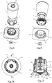
- the Figures 1 to 5 represent an electrical household appliance for culinary preparation, of the mixer type, according to a first embodiment of the invention, the apparatus comprising a housing 1 supporting a working receptacle 2 adapted to contain liquid or solid foodstuffs.
- the working container 2 is closed by a removable cover 3 having an opening 30 allowing the introduction of food inside the working container without having to lift the cover 3, the housing 1 typically containing a motor 4 whose implementation en route is controlled by means of a control button 14.
- the motor 4 allows the driving of a rotary tool 20, visible on the figure 5 disposed in the bottom of the working container 2, the rotary tool 20 being supported by the bottom of the working container 2 and including a drive shaft passing through the bottom of the working container 2.
- the housing 1 is pivotally mounted on a base 5 and comprises for this purpose a bottom wall 10, advantageously provided with ventilation slots 11, having the shape of a spherical cap which rests against a spherical guide surface 50 of the base 5, the guide surface 50 having a shape complementary to that of the wall 10 of the housing so that the bottom wall 10 can slide on the guide surface 50 by causing a pivoting movement of the housing 1.
- the guide surface 50 of the base is formed on a support wall 51 disposed at the upper end of a cylindrical wall 52 projecting vertically in the center of the base 5, the support wall 51 having a central opening 53 in which is engaged a pin 6 integral with a holding cup 7 which is positioned under the support wall 51, the holding cup 7 being fixed to the bottom wall 10 by means of a screw and having a spherical shape matching the radius of curvature of the support wall 51.
- the pin 6 is advantageously constituted by a first portion protruding from the bottom wall 10 of the housing and by a second portion projecting from the holding cup 7, the pin 6 having a height slightly greater than the thickness of the support wall 51 so as to allow the free rotation of the housing 1 and having a width greater than the width of the opening 53 to prevent the lifting of the housing 1 relative to the base 5.
- the spherical guide surface 50 of the support wall 51 has a radius of curvature of the order of 6 cm and the central opening 53 has a diameter of the order of 3.5 cm so as to that the working receptacle 2 can incline of the order of 10 ° in all directions relative to the vertical axis, the holding cup 7 having a diameter of about 5 cm.
- the base 5 comprises a frustoconical base 54 in the center of which the cylindrical wall 52 is vertically protruding, an annular groove 55 being formed between the upper end of the frustoconical base 54 and the cylindrical wall 52.
- the cylindrical wall 52 is fixed to the base by three bridges 52A, distributed at 120 °, connecting the lower end of the cylindrical wall 52 to the base 5, these bridges 52A being situated substantially at the base of the base 5 so that it results above these bridges 52A a space at the annular groove 55 wherein an annular locking ring 8 is inserted.
- the locking ring 8 comprises a gripping tab 81 and comprises an outer surface provided with two helical grooves 80 in which two lugs 56 carried by the base 5 engage, the two lugs 56 being arranged at 180 °, one of the other and cooperating with the groove 80 to generate a vertical displacement of the locking ring 8 on a stroke of the order of 15 mm when the locking ring 8 is rotated 120 ° from a retracted position, illustrated on the Figures 1, 3 and 4 , until a locking position illustrated on the figure 2 , the base 5 comprising resilient locking means, not shown in the figures, for immobilizing the locking ring in the retracted position and in the locking position.
- the upper end of the locking ring 8 is recessed with respect to the upper end of the cylindrical wall 52 so that there is a space between the upper end of the base 5 and a rib 12 formed peripheral edge of the bottom wall 10 of the housing 1.
- Such a space allows free rotation of the housing 1 on the base 5 in all directions to an inclination of about 10 ° of the working receptacle 2 relative to the longitudinal axis of the base 5 normal to the work plane as illustrated in the Figures 3 and 4 , the pin 6 carried by the lower wall 10 then abutting the edge of the central opening 53 to limit the inclination of the working receptacle 2.
- the locking ring 8 fills the space between the upper end of the base 5 and the rib 12 of the housing 1 so that the upper edge of the locking ring 8 bears against the rib 12 and blocks the housing 1 in a position in which the longitudinal axis of the motor 4 is oriented substantially vertically, any inclination movement of the housing 1 relative to the vertical axis being prevented by the presence of the locking ring 8.
- the apparatus thus produced has the advantage of being simple and economical to achieve and can be used with the locking ring in position. retracted, especially to facilitate the mixing of viscous preparations, or in blocking position when mixing more fluid preparations.
- the user can grasp the container with one hand to tilt it in different orientations up to an angle of up to 10 ° with respect to the vertical, such an inclination to modify the orientation of the mixing flow generated by the rotation of the rotary tool and reduce the power consumed by the engine during the production of viscous recipes.
- the housing can be locked in a vertical position to reduce the risk of overflow from the top of the working container.
- the locking ring has the advantage of being perfectly visible when it occupies the locking position, which makes it possible to clearly inform the user on the blocking state of the working container.
- the locking ring may advantageously be made in a bright color, distinct from that of the rest of the housing, in order to be even more visible to the user.
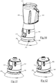
- FIGS. 10 to 15 illustrate a food preparation apparatus, mixer type, according to a second embodiment of the invention.
- the apparatus comprises a housing 101 supporting a removable working receptacle 102 capable of containing liquid or solid foodstuffs, the working receptacle 102 comprising an envelope provided with a gripping handle 121 and a spout 122.
- the housing 101 contains a motor 104 whose startup and operating speed are controlled by means of a control button 114 carried by an outer casing 113 of the housing 101, the motor 104 allowing, in a manner known per se, the driving a rotary tool carried by a base, removable or not, defining the bottom of the working container, not visible in the figures.
- the housing 101 has a spherical bottom wall 110, provided with ventilation slots 111, which comes to rest against a guide surface 150 carried by a base 105, the guide surface 150 having a spherical shape complementary to that of the bottom wall 110 of the housing so that the bottom wall 110 can slide on the guide surface 150 by generating a pivoting movement of the housing 101.
- the guide surface 150 of the base is formed on a perforated support wall 151 having a central opening 153 having a diameter of the order of 4 cm in which a pin 106 secured to a holding cup 107 having characteristics is engaged. similar to the holding cup 7 described for the first embodiment.
- the base 105 includes suction cups 154 for fixing the base 105 on a work plane and the support wall 151 comprises a projection 152 projecting, visible on the Figures 13A and 15 , which engages in a radial groove 112 formed in the bottom wall 110 of the housing so that the pivoting movement of the housing 101 on the base 105 can only be effected forward and / or towards the rear of the device, on an inclination of about 15 ° relative to the vertical.
- the bottom wall 110 of the casing is integrated with a support piece 115 on which the motor 104 is fixed, the support piece 115 having a diameter slightly smaller than that of the outer casing 113 of the casing so that a space results. between the support member 115 and the outer casing 113 of the housing in which a ring-shaped locking ring 108 is inserted.
- the locking ring 108 comprises a gripping tongue 181 and comprises an inner surface provided with helical ribs 180 which cooperate with helical guide tracks 116 formed on a peripheral wall of the support piece 115 to generate a vertical displacement of the ring locking 108 on a stroke of the order of 15 mm when the locking ring is rotated 45 ° from a retracted position, illustrated on the Figures 11 and 12 , to a locking position illustrated on the figure 10 .
- the lower end of the locking ring 108 is recessed with respect to the upper edge of the base 105 so that there is a space under the outer casing 113 of the housing allowing the free rotation of the housing 101 forwards or backwards to an inclination of the order of 15 ° of the working receptacle 102 relative to the base 105.
- the locking ring 108 fills the space between the housing 101 and the base 105 so that the lower edge of the locking ring 108 abuts against the base 105 and blocks the housing 101 in a position in which the longitudinal axis of the motor 104 is oriented substantially vertically, any inclination movement of the housing 101 relative to the vertical axis being prevented by the presence of the locking ring 108.
- the locking ring 108 also comprises a locking rib 182 that engages resiliently in grooves 117 formed on the peripheral wall of the support member 115 to immobilize in rotation the locking ring 108 when the latter occupies the retracted position and the lock position.
- the apparatus made according to this second embodiment also has the advantage of being simple and economical to produce and can be used with either the locking ring in the retracted position, in particular to facilitate the mixing of viscous preparations, or in position blocking when mixing more fluid preparations.
- the apparatus may include biasing means tending to automatically return the working container to a vertical position when no pressure is exerted by the user on the working container.
- the base can receive a ballast instead, or in addition, suction cups to ensure good stability of the device when the container is inclined relative to the base.
- the support wall of the base may be disengaged pin so that the housing can rotate in all directions on the base when the locking ring takes the position retracted, as is the case for the first embodiment.
Landscapes
- Engineering & Computer Science (AREA)
- Mechanical Engineering (AREA)
- Food Science & Technology (AREA)
- Food-Manufacturing Devices (AREA)
Claims (11)
- Elektrisches Gerät für die Nahrungsmittelzubereitung, das einen Arbeitsbehälter (2; 102) und ein Gehäuse (1; 101) aufweist, das einen Motor (4; 104) zum Antrieb eines rotierenden Werkzeugs (20) am Boden des Arbeitsbehälters (2; 102) umschließt, wobei das Gehäuse (1; 101) an einem Sockel (5; 105) schwenkbar angebracht ist, der dazu bestimmt ist, auf einer Arbeitsfläche aufzuliegen, wobei das Gehäuse (1; 101) eine untere Wand (10; 110) aufweist, die auf einer Führungsfläche (50; 150), die von dem Sockel (5; 105) getragen wird, aufliegt, wobei die untere Wand (10; 110) auf der Führungsfläche (50; 150) während des Schwenkens des Gehäuses (1; 101) gleitet, wodurch die Drehführung des Gehäuses (1; 101) sichergestellt wird, dadurch gekennzeichnet, dass die untere Wand (10; 110) kugelförmig ist, und dass die Führungsfläche (50; 150) eine komplementäre kugelförmige Form aufweist.
- Gerät nach Anspruch 1, dadurch gekennzeichnet, dass die kugelförmige Führungsfläche (50; 150) an einer Stützwand (51; 151) des Sockels vorgesehen ist, die eine Öffnung (53; 153) umfasst, in die ein Zapfen (6; 106) eingreift, wobei sich der Zapfen (6; 106) seitlich in der Öffnung (53; 153) bewegen kann und ein Ende umfasst, das an einer Halteschale (7; 107) befestigt ist, die unter der Stützwand (51; 151) positioniert ist.
- Gerät nach einem der Ansprüche 1 bis 2, dadurch gekennzeichnet, dass das Gehäuse (1; 101) um mindestens 10° und vorzugsweise mindestens 20° an dem Sockel (5; 105) schwenkbar ist.
- Gerät nach einem der Ansprüche 1 bis 3, dadurch gekennzeichnet, dass es eine Verriegelungsvorrichtung aufweist, die es ermöglicht, das Gehäuse (1; 101) an dem Sockel (5; 105) in einer vorbestimmten Arbeitsposition zu immobilisieren.
- Gerät nach Anspruch 4, dadurch gekennzeichnet, dass es die Verriegelungsvorrichtung ermöglicht, das Gehäuse (1; 101) auf dem Sockel (5; 105) in einer Position zu immobilisieren, in der sich der Arbeitsbehälter (2; 102) vertikal erstreckt.
- Gerät nach Anspruch 5, dadurch gekennzeichnet, dass die Verriegelungsvorrichtung einen Blockierring (8; 108) aufweist, der zwischen einer verriegelten Position, in der sich der Blockierring (8; 108) zwischen dem Sockel (5; 105) und dem Gehäuse (1; 101) erstreckt und ein Schwenken des Gehäuses verhindert, und einer zurückgezogenen Position bewegbar ist, in der der Blockierring (8; 108) einen Raum freigibt, der ein Schwenken des Gehäuses (1; 101) auf dem Sockel (5; 105) ermöglicht.
- Gerät nach Anspruch 6, dadurch gekennzeichnet, dass der Blockierring (8; 108) in einer Schraubenbewegung zwischen der zurückgezogenen Position und der verriegelten Position drehbar ist.
- Gerät nach Anspruch 7, dadurch gekennzeichnet, dass der Blockierring (8; 108) mit einer Grifflasche (81; 181) versehen ist.
- Gerät nach einem der Ansprüche 6 bis 8, dadurch gekennzeichnet, dass der Blockierring (8; 108) von dem Sockel (5; 105) getragen wird und sich in dem Sockel (5; 105) zurückgezogen befindet, wenn er die zurückgezogene Position einnimmt, und an dem Rand der unteren Wand (10; 110) des Gehäuses (1; 101) anliegt, wenn er die verriegelte Position einnimmt.
- Gerät nach einem der Ansprüche 6 bis 8, dadurch gekennzeichnet, dass der Blockierring (8; 108) von dem Gehäuse (1; 101) getragen wird und sich zurückgezogen in dem Gehäuse (1; 101) befindet, wenn er die zurückgezogene Position einnimmt, und an dem Rand des Sockels (5; 105) anliegt, wenn er die verriegelte Position einnimmt.
- Gerät nach einem der Ansprüche 1 bis 10, dadurch gekennzeichnet, dass der Sockel (105) Saugnäpfe (154) aufweist, die es ermöglichen, den Sockel (105) auf der Arbeitsebene zu befestigen.
Applications Claiming Priority (2)
| Application Number | Priority Date | Filing Date | Title |
|---|---|---|---|
| FR1550555A FR3031890B1 (fr) | 2015-01-23 | 2015-01-23 | Appareil electromenager comprenant un recipient de travail et un boitier moteur monte pivotant sur un socle |
| PCT/FR2016/050125 WO2016116714A1 (fr) | 2015-01-23 | 2016-01-21 | Appareil électroménager comprenant un récipient de travail et un boîtier moteur monte pivotant sur un socle |
Publications (2)
| Publication Number | Publication Date |
|---|---|
| EP3247247A1 EP3247247A1 (de) | 2017-11-29 |
| EP3247247B1 true EP3247247B1 (de) | 2018-11-28 |
Family
ID=54014890
Family Applications (1)
| Application Number | Title | Priority Date | Filing Date |
|---|---|---|---|
| EP16702758.0A Not-in-force EP3247247B1 (de) | 2015-01-23 | 2016-01-21 | Elektrisches haushaltsgerät mit arbeitsbehälter und auf einem sockel schwenkbar montierten maschinengehäuse |
Country Status (7)
| Country | Link |
|---|---|
| EP (1) | EP3247247B1 (de) |
| CN (1) | CN107205586B (de) |
| BR (1) | BR112017015376B1 (de) |
| CO (1) | CO2017007444A2 (de) |
| FR (1) | FR3031890B1 (de) |
| MX (1) | MX2017009451A (de) |
| WO (1) | WO2016116714A1 (de) |
Families Citing this family (1)
| Publication number | Priority date | Publication date | Assignee | Title |
|---|---|---|---|---|
| KR101760710B1 (ko) * | 2017-02-13 | 2017-07-24 | (주)상원 | 상하이동 및 스윙형 믹서기 |
Family Cites Families (7)
| Publication number | Priority date | Publication date | Assignee | Title |
|---|---|---|---|---|
| US2330860A (en) * | 1938-10-06 | 1943-10-05 | A F Dormeyer Mfg Co | Food mixer support |
| DE975534C (de) * | 1954-07-27 | 1961-12-28 | Naujoks & Stolle K G | Elektromotorischer Antriebssockel fuer aufsetzbare Kuechengeraete |
| GB8406130D0 (en) * | 1984-03-08 | 1984-04-11 | Thorn Emi Domestic Appliances | Food processing arrangement |
| DE20307144U1 (de) * | 2003-05-07 | 2003-07-10 | Gebr. Funke KG, 59889 Eslohe | Vorrichtung zur Aufnahme von Produkten, insbesondere Lebensmitteln |
| US7717613B1 (en) | 2008-12-10 | 2010-05-18 | Edward Epps | Portable blender with swiveling base |
| FR2957508B1 (fr) * | 2010-03-22 | 2012-03-23 | Seb Sa | Appareil electromenager de preparation culinaire comportant un boitier moteur destine a recevoir differents types d'accessoires amovibles |
| FR2960759B1 (fr) * | 2010-06-08 | 2012-06-15 | Seb Sa | Appareil electromenager de preparation culinaire comportant un recipient de travail ferme par un couvercle amovible |
-
2015
- 2015-01-23 FR FR1550555A patent/FR3031890B1/fr not_active Expired - Fee Related
-
2016
- 2016-01-21 EP EP16702758.0A patent/EP3247247B1/de not_active Not-in-force
- 2016-01-21 BR BR112017015376-9A patent/BR112017015376B1/pt not_active IP Right Cessation
- 2016-01-21 WO PCT/FR2016/050125 patent/WO2016116714A1/fr not_active Ceased
- 2016-01-21 CN CN201680006651.9A patent/CN107205586B/zh active Active
- 2016-01-21 MX MX2017009451A patent/MX2017009451A/es unknown
-
2017
- 2017-07-27 CO CONC2017/0007444A patent/CO2017007444A2/es unknown
Non-Patent Citations (1)
| Title |
|---|
| None * |
Also Published As
| Publication number | Publication date |
|---|---|
| BR112017015376A2 (pt) | 2018-01-16 |
| CN107205586A (zh) | 2017-09-26 |
| CO2017007444A2 (es) | 2017-09-11 |
| BR112017015376B1 (pt) | 2021-11-30 |
| FR3031890A1 (fr) | 2016-07-29 |
| CN107205586B (zh) | 2019-09-24 |
| MX2017009451A (es) | 2017-11-08 |
| WO2016116714A1 (fr) | 2016-07-28 |
| FR3031890B1 (fr) | 2017-02-10 |
| EP3247247A1 (de) | 2017-11-29 |
Similar Documents
| Publication | Publication Date | Title |
|---|---|---|
| EP2404536B1 (de) | Arbeitsbehälter, der eine abnehmbare Halterungsplatte umfasst, und Elektrohaushaltsgerät zur Essenszubereitung, das mit einem solchen Behälter ausgestattet ist | |
| EP2394547B1 (de) | Elektrohaushaltsgerät zur Essenszubereitung, das aus einem mit einem abnehmbaren Deckel verschlossenen Arbeitsbehälter besteht | |
| WO2007077341A1 (fr) | Recipient de cuisine avec au moins un moyen de prehension pivotant | |
| FR2940033A1 (fr) | Appareil electromenager de preparation culinaire comportant un premier et un deuxieme recipients de travail sur un boitier | |
| FR3020258A1 (fr) | Appareil de cuisson sous pression a organe de commande manuel relevable | |
| EP3247247A1 (de) | Elektrisches haushaltsgerät mit arbeitsbehälter und auf einem sockel schwenkbar montierten maschinengehäuse | |
| EP3079545B1 (de) | Haushaltsvorrichtung zur speisenzubereitung mit einem unterarm und einem drehbar am unterarm montierten oberarm | |
| EP1858633B1 (de) | Mixerähnliches elektrisches kochgerät mit rührer | |
| EP3079544B1 (de) | Haushaltsgerät zur lebensmittelzubereitung mit einem unterem arm an einem sockel und einem oberem arm, der über scharniere mit dem unteren arm verbunden ist | |
| EP1520499B1 (de) | Elektrisches Haushaltsgerät zur Nahrungszubereitung | |
| EP3079542B1 (de) | Haushaltsgerät zur lebensmittelzubereitung mit einem unterem arm an einem sockel und einem oberem arm, der über scharniere mit dem unteren arm verbunden ist | |
| WO2005089608A1 (fr) | Appareil electromenager de preparation culinaire | |
| EP3398489B1 (de) | Getränkezubereitungsmaschine, die mit einer versenkbaren halterung für behälter ausgestattet ist | |
| EP3922145A1 (de) | Kochgerät für lebensmittel, das einen herausnehmbaren kochbehälter umfasst | |
| EP3079543B1 (de) | Haushaltsgerät zur lebensmittelzubereitung mit einem sockel, einem unter arm und einem oberem arm, die über scharniere miteinander verbunden sind | |
| FR3146085A1 (fr) | Ensemble de coupe en spirale d’aliment et robot culinaire comprenant un tel ensemble de coupe | |
| EP4623765A1 (de) | Elektrische brühmaschine mit einem infusionszubehör mit einer beweglichen greifvorrichtung | |
| FR2771061A1 (fr) | Essuie-glace de vehicule automobile comportant des moyens de verrouillage en position relevee | |
| FR2607370A1 (fr) | Dispositif a element telescopique pour presenter un produit solide, notamment un rouge a levres sous forme de baton, de section droite quelconque | |
| EP2745752B1 (de) | Deckel eines Ausgussgefäßes, und Einheit für die Getränkeausgabe, die einen solchen Deckel und ein solches Ausgussgefäß umfasst | |
| FR3138286A1 (fr) | Appareil de mixage et de mélange | |
| FR3114806A1 (fr) | Dispositif de maintien d'un robinet de soutirage d'un conteneur | |
| FR2824247A1 (fr) | Machine a boissons chaudes comportant un receptacle pivotant perfore pour matieres aromatiques |
Legal Events
| Date | Code | Title | Description |
|---|---|---|---|
| STAA | Information on the status of an ep patent application or granted ep patent |
Free format text: STATUS: THE INTERNATIONAL PUBLICATION HAS BEEN MADE |
|
| PUAI | Public reference made under article 153(3) epc to a published international application that has entered the european phase |
Free format text: ORIGINAL CODE: 0009012 |
|
| STAA | Information on the status of an ep patent application or granted ep patent |
Free format text: STATUS: REQUEST FOR EXAMINATION WAS MADE |
|
| 17P | Request for examination filed |
Effective date: 20170801 |
|
| AK | Designated contracting states |
Kind code of ref document: A1 Designated state(s): AL AT BE BG CH CY CZ DE DK EE ES FI FR GB GR HR HU IE IS IT LI LT LU LV MC MK MT NL NO PL PT RO RS SE SI SK SM TR |
|
| AX | Request for extension of the european patent |
Extension state: BA ME |
|
| DAV | Request for validation of the european patent (deleted) | ||
| DAX | Request for extension of the european patent (deleted) | ||
| GRAP | Despatch of communication of intention to grant a patent |
Free format text: ORIGINAL CODE: EPIDOSNIGR1 |
|
| STAA | Information on the status of an ep patent application or granted ep patent |
Free format text: STATUS: GRANT OF PATENT IS INTENDED |
|
| INTG | Intention to grant announced |
Effective date: 20180618 |
|
| GRAS | Grant fee paid |
Free format text: ORIGINAL CODE: EPIDOSNIGR3 |
|
| GRAA | (expected) grant |
Free format text: ORIGINAL CODE: 0009210 |
|
| STAA | Information on the status of an ep patent application or granted ep patent |
Free format text: STATUS: THE PATENT HAS BEEN GRANTED |
|
| AK | Designated contracting states |
Kind code of ref document: B1 Designated state(s): AL AT BE BG CH CY CZ DE DK EE ES FI FR GB GR HR HU IE IS IT LI LT LU LV MC MK MT NL NO PL PT RO RS SE SI SK SM TR |
|
| REG | Reference to a national code |
Ref country code: CH Ref legal event code: EP |
|
| REG | Reference to a national code |
Ref country code: AT Ref legal event code: REF Ref document number: 1069242 Country of ref document: AT Kind code of ref document: T Effective date: 20181215 |
|
| REG | Reference to a national code |
Ref country code: IE Ref legal event code: FG4D Free format text: LANGUAGE OF EP DOCUMENT: FRENCH |
|
| REG | Reference to a national code |
Ref country code: DE Ref legal event code: R096 Ref document number: 602016007606 Country of ref document: DE |
|
| REG | Reference to a national code |
Ref country code: NL Ref legal event code: MP Effective date: 20181128 |
|
| REG | Reference to a national code |
Ref country code: LT Ref legal event code: MG4D |
|
| REG | Reference to a national code |
Ref country code: AT Ref legal event code: MK05 Ref document number: 1069242 Country of ref document: AT Kind code of ref document: T Effective date: 20181128 |
|
| PG25 | Lapsed in a contracting state [announced via postgrant information from national office to epo] |
Ref country code: IS Free format text: LAPSE BECAUSE OF FAILURE TO SUBMIT A TRANSLATION OF THE DESCRIPTION OR TO PAY THE FEE WITHIN THE PRESCRIBED TIME-LIMIT Effective date: 20190328 Ref country code: FI Free format text: LAPSE BECAUSE OF FAILURE TO SUBMIT A TRANSLATION OF THE DESCRIPTION OR TO PAY THE FEE WITHIN THE PRESCRIBED TIME-LIMIT Effective date: 20181128 Ref country code: AT Free format text: LAPSE BECAUSE OF FAILURE TO SUBMIT A TRANSLATION OF THE DESCRIPTION OR TO PAY THE FEE WITHIN THE PRESCRIBED TIME-LIMIT Effective date: 20181128 Ref country code: NO Free format text: LAPSE BECAUSE OF FAILURE TO SUBMIT A TRANSLATION OF THE DESCRIPTION OR TO PAY THE FEE WITHIN THE PRESCRIBED TIME-LIMIT Effective date: 20190228 Ref country code: LT Free format text: LAPSE BECAUSE OF FAILURE TO SUBMIT A TRANSLATION OF THE DESCRIPTION OR TO PAY THE FEE WITHIN THE PRESCRIBED TIME-LIMIT Effective date: 20181128 Ref country code: LV Free format text: LAPSE BECAUSE OF FAILURE TO SUBMIT A TRANSLATION OF THE DESCRIPTION OR TO PAY THE FEE WITHIN THE PRESCRIBED TIME-LIMIT Effective date: 20181128 Ref country code: ES Free format text: LAPSE BECAUSE OF FAILURE TO SUBMIT A TRANSLATION OF THE DESCRIPTION OR TO PAY THE FEE WITHIN THE PRESCRIBED TIME-LIMIT Effective date: 20181128 Ref country code: BG Free format text: LAPSE BECAUSE OF FAILURE TO SUBMIT A TRANSLATION OF THE DESCRIPTION OR TO PAY THE FEE WITHIN THE PRESCRIBED TIME-LIMIT Effective date: 20190228 Ref country code: HR Free format text: LAPSE BECAUSE OF FAILURE TO SUBMIT A TRANSLATION OF THE DESCRIPTION OR TO PAY THE FEE WITHIN THE PRESCRIBED TIME-LIMIT Effective date: 20181128 |
|
| PG25 | Lapsed in a contracting state [announced via postgrant information from national office to epo] |
Ref country code: PT Free format text: LAPSE BECAUSE OF FAILURE TO SUBMIT A TRANSLATION OF THE DESCRIPTION OR TO PAY THE FEE WITHIN THE PRESCRIBED TIME-LIMIT Effective date: 20190328 Ref country code: SE Free format text: LAPSE BECAUSE OF FAILURE TO SUBMIT A TRANSLATION OF THE DESCRIPTION OR TO PAY THE FEE WITHIN THE PRESCRIBED TIME-LIMIT Effective date: 20181128 Ref country code: AL Free format text: LAPSE BECAUSE OF FAILURE TO SUBMIT A TRANSLATION OF THE DESCRIPTION OR TO PAY THE FEE WITHIN THE PRESCRIBED TIME-LIMIT Effective date: 20181128 Ref country code: GR Free format text: LAPSE BECAUSE OF FAILURE TO SUBMIT A TRANSLATION OF THE DESCRIPTION OR TO PAY THE FEE WITHIN THE PRESCRIBED TIME-LIMIT Effective date: 20190301 Ref country code: RS Free format text: LAPSE BECAUSE OF FAILURE TO SUBMIT A TRANSLATION OF THE DESCRIPTION OR TO PAY THE FEE WITHIN THE PRESCRIBED TIME-LIMIT Effective date: 20181128 |
|
| PG25 | Lapsed in a contracting state [announced via postgrant information from national office to epo] |
Ref country code: NL Free format text: LAPSE BECAUSE OF FAILURE TO SUBMIT A TRANSLATION OF THE DESCRIPTION OR TO PAY THE FEE WITHIN THE PRESCRIBED TIME-LIMIT Effective date: 20181128 |
|
| PG25 | Lapsed in a contracting state [announced via postgrant information from national office to epo] |
Ref country code: CZ Free format text: LAPSE BECAUSE OF FAILURE TO SUBMIT A TRANSLATION OF THE DESCRIPTION OR TO PAY THE FEE WITHIN THE PRESCRIBED TIME-LIMIT Effective date: 20181128 Ref country code: PL Free format text: LAPSE BECAUSE OF FAILURE TO SUBMIT A TRANSLATION OF THE DESCRIPTION OR TO PAY THE FEE WITHIN THE PRESCRIBED TIME-LIMIT Effective date: 20181128 Ref country code: DK Free format text: LAPSE BECAUSE OF FAILURE TO SUBMIT A TRANSLATION OF THE DESCRIPTION OR TO PAY THE FEE WITHIN THE PRESCRIBED TIME-LIMIT Effective date: 20181128 Ref country code: IT Free format text: LAPSE BECAUSE OF FAILURE TO SUBMIT A TRANSLATION OF THE DESCRIPTION OR TO PAY THE FEE WITHIN THE PRESCRIBED TIME-LIMIT Effective date: 20181128 |
|
| REG | Reference to a national code |
Ref country code: DE Ref legal event code: R097 Ref document number: 602016007606 Country of ref document: DE |
|
| PG25 | Lapsed in a contracting state [announced via postgrant information from national office to epo] |
Ref country code: EE Free format text: LAPSE BECAUSE OF FAILURE TO SUBMIT A TRANSLATION OF THE DESCRIPTION OR TO PAY THE FEE WITHIN THE PRESCRIBED TIME-LIMIT Effective date: 20181128 Ref country code: RO Free format text: LAPSE BECAUSE OF FAILURE TO SUBMIT A TRANSLATION OF THE DESCRIPTION OR TO PAY THE FEE WITHIN THE PRESCRIBED TIME-LIMIT Effective date: 20181128 Ref country code: SM Free format text: LAPSE BECAUSE OF FAILURE TO SUBMIT A TRANSLATION OF THE DESCRIPTION OR TO PAY THE FEE WITHIN THE PRESCRIBED TIME-LIMIT Effective date: 20181128 Ref country code: MC Free format text: LAPSE BECAUSE OF FAILURE TO SUBMIT A TRANSLATION OF THE DESCRIPTION OR TO PAY THE FEE WITHIN THE PRESCRIBED TIME-LIMIT Effective date: 20181128 Ref country code: SK Free format text: LAPSE BECAUSE OF FAILURE TO SUBMIT A TRANSLATION OF THE DESCRIPTION OR TO PAY THE FEE WITHIN THE PRESCRIBED TIME-LIMIT Effective date: 20181128 |
|
| REG | Reference to a national code |
Ref country code: CH Ref legal event code: PL |
|
| PG25 | Lapsed in a contracting state [announced via postgrant information from national office to epo] |
Ref country code: LU Free format text: LAPSE BECAUSE OF NON-PAYMENT OF DUE FEES Effective date: 20190121 |
|
| PLBE | No opposition filed within time limit |
Free format text: ORIGINAL CODE: 0009261 |
|
| STAA | Information on the status of an ep patent application or granted ep patent |
Free format text: STATUS: NO OPPOSITION FILED WITHIN TIME LIMIT |
|
| REG | Reference to a national code |
Ref country code: BE Ref legal event code: MM Effective date: 20190131 |
|
| REG | Reference to a national code |
Ref country code: IE Ref legal event code: MM4A |
|
| PG25 | Lapsed in a contracting state [announced via postgrant information from national office to epo] |
Ref country code: SI Free format text: LAPSE BECAUSE OF FAILURE TO SUBMIT A TRANSLATION OF THE DESCRIPTION OR TO PAY THE FEE WITHIN THE PRESCRIBED TIME-LIMIT Effective date: 20181128 |
|
| 26N | No opposition filed |
Effective date: 20190829 |
|
| PG25 | Lapsed in a contracting state [announced via postgrant information from national office to epo] |
Ref country code: BE Free format text: LAPSE BECAUSE OF NON-PAYMENT OF DUE FEES Effective date: 20190131 |
|
| PG25 | Lapsed in a contracting state [announced via postgrant information from national office to epo] |
Ref country code: CH Free format text: LAPSE BECAUSE OF NON-PAYMENT OF DUE FEES Effective date: 20190131 Ref country code: LI Free format text: LAPSE BECAUSE OF NON-PAYMENT OF DUE FEES Effective date: 20190131 |
|
| PG25 | Lapsed in a contracting state [announced via postgrant information from national office to epo] |
Ref country code: IE Free format text: LAPSE BECAUSE OF NON-PAYMENT OF DUE FEES Effective date: 20190121 |
|
| PG25 | Lapsed in a contracting state [announced via postgrant information from national office to epo] |
Ref country code: TR Free format text: LAPSE BECAUSE OF FAILURE TO SUBMIT A TRANSLATION OF THE DESCRIPTION OR TO PAY THE FEE WITHIN THE PRESCRIBED TIME-LIMIT Effective date: 20181128 |
|
| PG25 | Lapsed in a contracting state [announced via postgrant information from national office to epo] |
Ref country code: MT Free format text: LAPSE BECAUSE OF FAILURE TO SUBMIT A TRANSLATION OF THE DESCRIPTION OR TO PAY THE FEE WITHIN THE PRESCRIBED TIME-LIMIT Effective date: 20181128 |
|
| PG25 | Lapsed in a contracting state [announced via postgrant information from national office to epo] |
Ref country code: CY Free format text: LAPSE BECAUSE OF FAILURE TO SUBMIT A TRANSLATION OF THE DESCRIPTION OR TO PAY THE FEE WITHIN THE PRESCRIBED TIME-LIMIT Effective date: 20181128 |
|
| PG25 | Lapsed in a contracting state [announced via postgrant information from national office to epo] |
Ref country code: HU Free format text: LAPSE BECAUSE OF FAILURE TO SUBMIT A TRANSLATION OF THE DESCRIPTION OR TO PAY THE FEE WITHIN THE PRESCRIBED TIME-LIMIT; INVALID AB INITIO Effective date: 20160121 |
|
| PGFP | Annual fee paid to national office [announced via postgrant information from national office to epo] |
Ref country code: GB Payment date: 20220120 Year of fee payment: 7 Ref country code: DE Payment date: 20220114 Year of fee payment: 7 |
|
| PGFP | Annual fee paid to national office [announced via postgrant information from national office to epo] |
Ref country code: FR Payment date: 20220131 Year of fee payment: 7 |
|
| PG25 | Lapsed in a contracting state [announced via postgrant information from national office to epo] |
Ref country code: MK Free format text: LAPSE BECAUSE OF FAILURE TO SUBMIT A TRANSLATION OF THE DESCRIPTION OR TO PAY THE FEE WITHIN THE PRESCRIBED TIME-LIMIT Effective date: 20181128 |
|
| REG | Reference to a national code |
Ref country code: DE Ref legal event code: R119 Ref document number: 602016007606 Country of ref document: DE |
|
| GBPC | Gb: european patent ceased through non-payment of renewal fee |
Effective date: 20230121 |
|
| PG25 | Lapsed in a contracting state [announced via postgrant information from national office to epo] |
Ref country code: GB Free format text: LAPSE BECAUSE OF NON-PAYMENT OF DUE FEES Effective date: 20230121 Ref country code: DE Free format text: LAPSE BECAUSE OF NON-PAYMENT OF DUE FEES Effective date: 20230801 |
|
| PG25 | Lapsed in a contracting state [announced via postgrant information from national office to epo] |
Ref country code: FR Free format text: LAPSE BECAUSE OF NON-PAYMENT OF DUE FEES Effective date: 20230131 |