EP3247251B1 - Staubsammelvorrichtung für staubsauger - Google Patents
Staubsammelvorrichtung für staubsauger Download PDFInfo
- Publication number
- EP3247251B1 EP3247251B1 EP16740366.6A EP16740366A EP3247251B1 EP 3247251 B1 EP3247251 B1 EP 3247251B1 EP 16740366 A EP16740366 A EP 16740366A EP 3247251 B1 EP3247251 B1 EP 3247251B1
- Authority
- EP
- European Patent Office
- Prior art keywords
- dust
- cyclone
- unit
- dust collector
- fine dust
- Prior art date
- Legal status (The legal status is an assumption and is not a legal conclusion. Google has not performed a legal analysis and makes no representation as to the accuracy of the status listed.)
- Active
Links
Images



Classifications
-
- A—HUMAN NECESSITIES
- A47—FURNITURE; DOMESTIC ARTICLES OR APPLIANCES; COFFEE MILLS; SPICE MILLS; SUCTION CLEANERS IN GENERAL
- A47L—DOMESTIC WASHING OR CLEANING; SUCTION CLEANERS IN GENERAL
- A47L9/00—Details or accessories of suction cleaners, e.g. mechanical means for controlling the suction or for effecting pulsating action; Storing devices specially adapted to suction cleaners or parts thereof; Carrying-vehicles specially adapted for suction cleaners
- A47L9/10—Filters; Dust separators; Dust removal; Automatic exchange of filters
- A47L9/16—Arrangement or disposition of cyclones or other devices with centrifugal action
- A47L9/1608—Cyclonic chamber constructions
-
- A—HUMAN NECESSITIES
- A47—FURNITURE; DOMESTIC ARTICLES OR APPLIANCES; COFFEE MILLS; SPICE MILLS; SUCTION CLEANERS IN GENERAL
- A47L—DOMESTIC WASHING OR CLEANING; SUCTION CLEANERS IN GENERAL
- A47L9/00—Details or accessories of suction cleaners, e.g. mechanical means for controlling the suction or for effecting pulsating action; Storing devices specially adapted to suction cleaners or parts thereof; Carrying-vehicles specially adapted for suction cleaners
- A47L9/10—Filters; Dust separators; Dust removal; Automatic exchange of filters
- A47L9/106—Dust removal
- A47L9/108—Dust compression means
-
- A—HUMAN NECESSITIES
- A47—FURNITURE; DOMESTIC ARTICLES OR APPLIANCES; COFFEE MILLS; SPICE MILLS; SUCTION CLEANERS IN GENERAL
- A47L—DOMESTIC WASHING OR CLEANING; SUCTION CLEANERS IN GENERAL
- A47L9/00—Details or accessories of suction cleaners, e.g. mechanical means for controlling the suction or for effecting pulsating action; Storing devices specially adapted to suction cleaners or parts thereof; Carrying-vehicles specially adapted for suction cleaners
- A47L9/10—Filters; Dust separators; Dust removal; Automatic exchange of filters
- A47L9/12—Dry filters
- A47L9/125—Dry filters funnel-shaped
-
- A—HUMAN NECESSITIES
- A47—FURNITURE; DOMESTIC ARTICLES OR APPLIANCES; COFFEE MILLS; SPICE MILLS; SUCTION CLEANERS IN GENERAL
- A47L—DOMESTIC WASHING OR CLEANING; SUCTION CLEANERS IN GENERAL
- A47L9/00—Details or accessories of suction cleaners, e.g. mechanical means for controlling the suction or for effecting pulsating action; Storing devices specially adapted to suction cleaners or parts thereof; Carrying-vehicles specially adapted for suction cleaners
- A47L9/10—Filters; Dust separators; Dust removal; Automatic exchange of filters
- A47L9/16—Arrangement or disposition of cyclones or other devices with centrifugal action
- A47L9/1616—Multiple arrangement thereof
-
- A—HUMAN NECESSITIES
- A47—FURNITURE; DOMESTIC ARTICLES OR APPLIANCES; COFFEE MILLS; SPICE MILLS; SUCTION CLEANERS IN GENERAL
- A47L—DOMESTIC WASHING OR CLEANING; SUCTION CLEANERS IN GENERAL
- A47L9/00—Details or accessories of suction cleaners, e.g. mechanical means for controlling the suction or for effecting pulsating action; Storing devices specially adapted to suction cleaners or parts thereof; Carrying-vehicles specially adapted for suction cleaners
- A47L9/10—Filters; Dust separators; Dust removal; Automatic exchange of filters
- A47L9/16—Arrangement or disposition of cyclones or other devices with centrifugal action
- A47L9/1616—Multiple arrangement thereof
- A47L9/1625—Multiple arrangement thereof for series flow
-
- A—HUMAN NECESSITIES
- A47—FURNITURE; DOMESTIC ARTICLES OR APPLIANCES; COFFEE MILLS; SPICE MILLS; SUCTION CLEANERS IN GENERAL
- A47L—DOMESTIC WASHING OR CLEANING; SUCTION CLEANERS IN GENERAL
- A47L9/00—Details or accessories of suction cleaners, e.g. mechanical means for controlling the suction or for effecting pulsating action; Storing devices specially adapted to suction cleaners or parts thereof; Carrying-vehicles specially adapted for suction cleaners
- A47L9/10—Filters; Dust separators; Dust removal; Automatic exchange of filters
- A47L9/16—Arrangement or disposition of cyclones or other devices with centrifugal action
- A47L9/1616—Multiple arrangement thereof
- A47L9/1641—Multiple arrangement thereof for parallel flow
-
- A—HUMAN NECESSITIES
- A47—FURNITURE; DOMESTIC ARTICLES OR APPLIANCES; COFFEE MILLS; SPICE MILLS; SUCTION CLEANERS IN GENERAL
- A47L—DOMESTIC WASHING OR CLEANING; SUCTION CLEANERS IN GENERAL
- A47L9/00—Details or accessories of suction cleaners, e.g. mechanical means for controlling the suction or for effecting pulsating action; Storing devices specially adapted to suction cleaners or parts thereof; Carrying-vehicles specially adapted for suction cleaners
- A47L9/10—Filters; Dust separators; Dust removal; Automatic exchange of filters
- A47L9/16—Arrangement or disposition of cyclones or other devices with centrifugal action
- A47L9/165—Construction of inlets
-
- A—HUMAN NECESSITIES
- A47—FURNITURE; DOMESTIC ARTICLES OR APPLIANCES; COFFEE MILLS; SPICE MILLS; SUCTION CLEANERS IN GENERAL
- A47L—DOMESTIC WASHING OR CLEANING; SUCTION CLEANERS IN GENERAL
- A47L9/00—Details or accessories of suction cleaners, e.g. mechanical means for controlling the suction or for effecting pulsating action; Storing devices specially adapted to suction cleaners or parts thereof; Carrying-vehicles specially adapted for suction cleaners
- A47L9/10—Filters; Dust separators; Dust removal; Automatic exchange of filters
- A47L9/16—Arrangement or disposition of cyclones or other devices with centrifugal action
- A47L9/1683—Dust collecting chambers; Dust collecting receptacles
-
- B—PERFORMING OPERATIONS; TRANSPORTING
- B01—PHYSICAL OR CHEMICAL PROCESSES OR APPARATUS IN GENERAL
- B01D—SEPARATION
- B01D39/00—Filtering material for liquid or gaseous fluids
- B01D39/10—Filter screens essentially made of metal
- B01D39/12—Filter screens essentially made of metal of wire gauze; of knitted wire; of expanded metal
-
- B—PERFORMING OPERATIONS; TRANSPORTING
- B01—PHYSICAL OR CHEMICAL PROCESSES OR APPARATUS IN GENERAL
- B01D—SEPARATION
- B01D45/00—Separating dispersed particles from gases or vapours by gravity, inertia, or centrifugal forces
- B01D45/12—Separating dispersed particles from gases or vapours by gravity, inertia, or centrifugal forces by centrifugal forces
- B01D45/16—Separating dispersed particles from gases or vapours by gravity, inertia, or centrifugal forces by centrifugal forces generated by the winding course of the gas stream, the centrifugal forces being generated solely or partly by mechanical means, e.g. fixed swirl vanes
-
- B—PERFORMING OPERATIONS; TRANSPORTING
- B01—PHYSICAL OR CHEMICAL PROCESSES OR APPARATUS IN GENERAL
- B01D—SEPARATION
- B01D50/00—Combinations of methods or devices for separating particles from gases or vapours
- B01D50/20—Combinations of devices covered by groups B01D45/00 and B01D46/00
-
- B—PERFORMING OPERATIONS; TRANSPORTING
- B04—CENTRIFUGAL APPARATUS OR MACHINES FOR CARRYING-OUT PHYSICAL OR CHEMICAL PROCESSES
- B04C—APPARATUS USING FREE VORTEX FLOW, e.g. CYCLONES
- B04C3/00—Apparatus in which the axial direction of the vortex flow following a screw-thread type line remains unchanged ; Devices in which one of the two discharge ducts returns centrally through the vortex chamber, a reverse-flow vortex being prevented by bulkheads in the central discharge duct
- B04C3/04—Multiple arrangement thereof
Definitions
- This specification relates to a dust collector for a vacuum cleaner, capable of collecting dust and fine dust by separating the dust and fine dust from air introduced into the vacuum cleaner through a multi-cyclone, and discharging the collected dust and fine dust.
- a vacuum cleaner is an electrical apparatus of introducing air using suction power generated by a suction motor and separating dust or dirt from the air to discharge clean air.
- Types of vacuum cleaners may be classified into i) a canister type, ii) an upright type, iii) a hand type, iv) a cylindrical floor type and the like.
- the canister type vacuum cleaner is a vacuum cleaner mostly used at home, which is a vacuum cleaner with a method of communicating a suction nozzle with a body through a connecting member.
- the canister type vacuum cleaner is appropriate for cleaning hard floors because of merely using sucking force for the cleaning.
- the upright type is a vacuum cleaner in which a suction nozzle and a cleaner body are integrally formed with each other.
- the upright type vacuum cleaner can clean even dust within a carpet, unlike the canister type vacuum cleaner, by virtue of employing a rotating brush.
- a second cyclone unit is laminated on a first cyclone unit, which may cause a problem of increasing a height of the dust collector.
- the dust collector of the multi-cyclone type is configured such that the second cyclone unit is disposed inside or outside the first cyclone unit.
- the lamination for the effective arrangement of the second cyclone unit has been proposed.
- steps increase, the overall height of the dust collector increases.
- a higher step also suffers from a reduced introduction of air flow.
- the overall height of the dust collector further increases.
- the related art cleaner has a limit in providing user convenience during a dust discharging process.
- vacuum cleaners in which dust are blown away during the process of discharging dust, and other vacuum cleaners requiring for a very complicated process to discharge dust.
- US 2007/143953 A1 discloses a vacuum cleaner including a main dust separation unit and a secondary dust separation unit.
- the vacuum cleaner comprises a main cyclone unit and a secondary cyclone unit.
- the main cyclone unit is provided in a dust collection unit and air passing through the main cyclone unit is introduced into the secondary cyclone unit via a connection duct. Dust separated by the secondary cyclone unit is introduced into a sub-chamber, which is positioned downstream of the secondary cyclone unit.
- US 2015/000077 A1 discloses a hand vacuum cleaner having a cyclonic cleaning stage.
- the cyclonic cleaning stage can be a multi-cyclone structure including a single cyclone chamber and a plurality of second cyclones.
- the structure further comprises a panel configured to be opened/closed downwards to enable the discharge of dust and fine dust at the same time.
- EP 1 857 032 A2 discloses a multi-cyclone structure including a primary cyclone unit and a secondary cyclone unit. Air coming from the primary cyclone unit is introduced to the secondary cyclone unit via a connection passage. The cyclones of the secondary cyclone unit are arranged parallel and their outlets are connected to a dust collection container.
- an aspect of the detailed description is to provide a dust collector for a vacuum cleaner with a novel structure, capable of laminating a second cyclone unit on a first cyclone unit by improving a multi-cyclone structure, and also improving a cleaning performance by efficiently arranging more second cyclones.
- Another aspect of the detailed description is to provide a dust collector, capable of collecting dust and fine dust in a separating manner and discharging the collected dust and fine dust in a simultaneous manner.
- Another aspect of the detailed description is to provide a dust collector, capable of compressing dust to facilitate a discharge of the dust.
- a dust collector for a vacuum cleaner including an outer case forming a lateral appearance of the dust collector, and provided with a first cyclone unit capable of filtering out dust from air introduced from outside and allowing an introduction of the dust-filtered air therein, and an upper case coupled to an upper portion of the outer case to cover the first cyclone unit, and provided with a second cyclone unit capable of separating fine dust from the air introduced into the first cyclone unit, and a fine dust collecting unit capable of collecting the fine dust separated through the second cyclone unit.
- the second cyclone unit may include a left cyclone portion and a right cyclone portion disposed at both left and right sides of the fine dust collecting unit and each having outlets, each which communicates with an inside of the fine dust collecting unit.
- Each of the left cyclone portion and the right cyclone portion may include a plurality of cyclones arranged in horizontal and vertical directions.
- An empty space between the plurality of cyclones may form an introduction passage communicating with inlets of the plurality of cyclones, respectively, such that the air introduced into the first cyclone unit is introduced into each of the inlets.
- One of the plurality of cyclones may be disposed on another cyclone, and an inlet of each of the plurality of cyclones may extend to a space formed between the one cyclone and the another cyclone.
- the dust collector for the vacuum cleaner may further include a cover member disposed to cover openings of the plurality of cyclones, respectively, and provided with vortex finders communicating with openings such that the fine dust-separated air is discharged, and an upper cover disposed to cover the upper case and provided with a discharge guide communicating the vortex finders with an exit of the dust collector.
- the fine dust collecting unit may communicate with a fine dust storage unit provided in the outer case.
- the first cyclone unit may include an inner housing communicating with an entrance of the dust collector through which air is introduced, and a mesh filter disposed in the inner housing and capable of separating dust from the air introduced into the inner housing.
- the inner housing may include a first part surrounding the mesh filter and spaced apart from the upper case such that dust is dischargeable, and a second part connecting the entrance of the dust collector to the first part, and extending toward an inner circumference of the first portion so as to generate a rotational flow of air introduced into the first part.
- a partition plate may be provided in an annular space between the outer case and the first portion.
- the partition plate may be disposed to cover at least part of the annular space and have an opening at one portion thereof such that dust filtered out through the first cyclone unit is introduced into a preset area of a dust storage unit disposed below the partition plate.
- the dust filtered out through the first cyclone unit may be collected in a dust storage unit, which is provided within the outer case in a manner of being independent of the fine dust storage unit.
- a lower cover may be provided at a lower portion of the outer case. The lower cover may form a bottom surface of the dust storage unit and the fine dust storage unit when closed, and be capable of simultaneously opening the dust storage unit and the fine dust storage unit when opened such that the dust and the fine dust are simultaneously discharged.
- the present invention may provide a dust collector for a vacuum cleaner.
- the dust collector may include a first cyclone unit provided in an outer case and capable of filtering out dust from externally-introduced air and allowing an introduction of the dust-filtered air therein, a second cyclone unit disposed above the first cyclone unit and capable of separating fine dust from the air introduced into the first cyclone unit, and a fine dust collecting unit capable of collecting fine dust separated through the second cyclone unit.
- the second cyclone unit may include a left cyclone portion and a right cyclone portion disposed at both left and right sides of the fine dust collecting unit and each having outlets, each of the outlets communicating with an inside of the fine dust collecting unit.
- a second cyclone unit is divided into a left cyclone portion and a right cyclone portion based on a fine dust collecting unit disposed above a first cyclone unit. This may allow for an efficient arrangement of more second cyclones, resulting in improvement of a cleaning performance of the vacuum cleaner.
- a handle may be provided between the left cyclone portion and the right cyclone portion which are arranged in a V-like shape, thereby facilitating an efficient use of a space.
- a dust storage unit and a fine dust storage unit may simultaneously be open upon detaching a lower cover, which may allow for simultaneous discharge of dust collected in the dust storage unit and fine dust collected in the fine dust storage unit.
- dust collected can be gathered by a pressing unit, which may result in preventing the collected dust from being scattered.
- a suffix such as “module” and “unit” may be used to refer to elements or components. Use of such a suffix herein is merely intended to facilitate description of the specification, and the suffix itself is not intended to give any special meaning or function.
- a singular representation may include a plural representation unless it represents a definitely different meaning from the context.
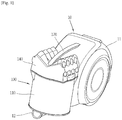
- FIG. 1 is a perspective view illustrating one example of a vacuum cleaner 10 in accordance with the present invention.
- the vacuum cleaner 10 may include a cleaner body 11 having a fan unit (not illustrated) generating sucking force (suction power).
- the fan unit may include a suction motor, and a suction fan that is rotated by the suction motor to generate the sucking force.
- the vacuum cleaner 10 may further include a suction nozzle (not illustrated) through which air containing foreign materials is introduced, and a connection member (not illustrated) by which the suction nozzle is connected to the cleaner body 11.
- a suction nozzle (not illustrated) through which air containing foreign materials is introduced
- a connection member (not illustrated) by which the suction nozzle is connected to the cleaner body 11.
- the basic configuration of the suction nozzle and the connection member is the same as that of the related art, so description thereof will be omitted.
- a suction unit 12 for sucking air introduced through the suction nozzle and foreign materials (substances) contained in the air may be provided at a lower end portion of a front surface of the cleaner body 11.
- the air and the foreign materials may be introduced into the suction unit 12 in response to an operation of the fan unit.
- the air and the foreign materials introduced in the suction unit 12 may then flow into a dust collector 100 and then be separated from each other in the dust collector 100.
- the dust collector 100 may be configured to collect foreign materials or dust by separating the foreign materials or dust from the sucked air, and discharge air without the dust.
- the dust collector 100 may be detachably configured on the cleaner body 11.
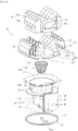
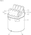
- FIG. 2 is an exploded conceptual view of the dust collector 100 illustrated in FIG. 1
- FIG. 3 is a conceptual view illustrating main components in the dust collector 100 illustrated in FIG. 2 in a separate manner.
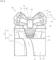
- FIG. 4 is a longitudinal sectional view of the dust collector 100 of FIG. 2 , taken along the line IV-IV
- FIG. 5 is a horizontal sectional view of the dust collector 100 of FIG. 2 , taken along the line V-V
- FIG. 6 is a longitudinal sectional view of the dust collector 100 of FIG. 2 , taken along the line VI-VI
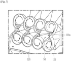
- FIG. 7 is a conceptual view of a second cyclone unit 122 illustrated in FIG. 3
- FIG. 8 is a conceptual view illustrating a state that a cover member 130 is coupled to the second cyclone unit 122 illustrated in FIG. 3 .
- FIGS. 1-10 illustrate the duct collector 100 applied to a canister type vacuum cleaner, but the dust collector 100 according to the present invention may not be necessarily limited to the upright type vacuum cleaner 10.
- the dust collector 100 according to the present invention may be also applicable to an upright type vacuum cleaner.
- air and foreign materials may be introduced into an entrance 100a of the dust collector 100 through the suction unit 12 by sucking force that is generated in the fan unit of the vacuum cleaner 10.
- the air which is introduced into the dust collector 100 through the entrance 100a may be filtered sequentially at a first cyclone unit 111 and a second cyclone unit 122 while flowing along a passage to be explained later, and then discharged through an exit 100b. Dust and fine dust separated from the air may be collected in a dust storage unit D1 and a fine dust storage unit D2 of the dust collector 100.
- a cyclone refers to an apparatus for providing rotational flow to fluid in which particles are floating to separate the particles from the fluid by a centrifugal force.
- the cyclone may separate foreign materials such as dust, fine dust and the like from air introduced into the cleaner body 11 by sucking force.
- dust relatively large dust
- fine dust relatively small dust
- ultra-fine dust dust smaller than "fine dust”
- the dust collector 100 may include an outer case 110, an upper case 120, a cover member 130, an upper cover 140 and a lower cover 150.
- the outer case 110 may define a lateral appearance of the dust collector 100.
- the outer case 110 may preferably be formed in a cylindrical shape, as illustrated in the drawing, but may not be limited to the shape.
- the outer case 110 may be formed in a polygonal columnar shape.
- a first cyclone unit 111 may be disposed in the outer case 110.
- the first cyclone unit 111 may be configured to filter out dust from air introduced along with foreign materials, and allow the dust-filtered air to be introduced into the dust collector 100.
- the first cyclone unit 111 may include an inner housing 111a and a mesh filter 111b.
- the inner housing 111a may be disposed in the outer case 110.
- the inner housing 111a may communicate with the entrance 100a disposed at the lower portion of the dust collector 100 such that air can be introduced into the dust collector 100.
- the inner housing 111a may be connected to the outer case 110 by a partition plate 112, which will be explained later, so as to configure an integral form with the outer case 110. Air which is introduced into the inner housing 111a through the entrance 100a may turn (rotate) along an inner circumference of the inner housing 111a.
- the inner housing 111a may include a first part 111a' and a second part 111a" disposed at upper and lower portions thereof, respectively.
- the first part 111a' may surround the mesh filter 111b, and form a space in which air can rotate (turn, spin) along the inner circumference of the inner housing 111a.
- the first part 111a' may be spaced apart from the upper case 120 such that dust can be discharged.
- the second part 111a" may be disposed to connect the entrance 100a of the dust collector 100 and the first part 111a' to each other. As illustrated, the second part 111a" may extend in a curved shape toward an inner circumference of the first part 111a', so as to induce a rotational flow of air introduced into the first part 111a'.
- the mesh filter 111b may be installed in the first part 111a' to separate dust from air introduced into the first part 111a'.
- the mesh filter 111b may have a mesh or porous shape to allow dust and fine dust to pass therethrough. Criteria of sizes to distinguish dust and fine dust from each other may be decided by the mesh filter 111b. Foreign materials which are small enough to pass through the mesh filter 111b may be classified into fine dust, and foreign materials which is large enough to fail to pass through the mesh filter 111b may be classified into dust.
- the mesh filter 111b may have a shape of a truncated cone whose sectional area is gradually reduced from top to bottom. The shape may facilitate dust stuck on the mesh filter 111b to be separated by the gravity.
- Air and foreign materials may be introduced into the inner housing 111a through the entrance 100a of the dust collector 100, and then rotate (spin) along the inner circumference of the inner housing 111a.
- the dust which is relatively heavier than air may gradually flow upward while spirally rotating along the inner circumference of the inner housing 111a. Afterwards, the dust may be discharged out of the first part 111a' by a centrifugal force through an open space between the first part 111a' and the upper case 120, and then collected in the dust storage unit D1 to be explained later.
- the first part 111a' may extend in an outwardly inclined manner toward its upper side.
- air may be introduced into the mesh filter 111b by sucking force through the mesh filter 111b.
- fine dust which is smaller than the dust may also be introduced into the mesh filter 111b along with the air.
- an internal structure of the dust collector 100 and the flow of air and foreign materials in the dust collector 100 can be checked.
- the upper case 120 may be mounted to a top of the outer case 110 to cover the first cyclone unit 111.
- the upper case 120 may include a cover unit 121, a second cyclone unit 122, and a fine dust collecting unit 123, which may be integrally formed of synthetic resin through injection molding or 3D-printing.
- the cover unit 121 may be formed in a shape of a flat plate and cover the upper portion of the outer case 110.
- a mesh filter mounting portion (not illustrated) for fixing the mesh filter 111b of the first cyclone unit 111 may be provided at a lower surface of the cover unit 121.
- the second cyclone unit 122 may be configured to separate fine dust from air introduced into the first cyclone unit 111.
- the second cyclone unit 122 may include a left cyclone portion 122' and a right cyclone portion 122" disposed at both left and right sides of the fine dust collecting unit 123, respectively.
- the fine dust collecting unit 123 may be disposed between the left cyclone portion 122' and the right cyclone portion 122", to collect fine dust separated through the second cyclone unit 122.
- Outlets 122b of the left cyclone portion 122' and the right cyclone portion 122" may communicate with an inside of the fine dust collecting unit 123, such that fine dust separated by the second cyclone unit 122 can be collected into the fine dust collecting unit 123.
- Each of the left cyclone portion 122' and the right cyclone portion 122" may include a plurality of cyclones which are arranged in at least one direction. This exemplary embodiment illustrates that each of the left cyclone portion 122' and the right cyclone portion 122" includes a plurality of cyclones arranged in horizontal and vertical directions on the cover unit 121.
- Each cyclone has a conic shape. Accordingly, when the plurality of cyclones are arranged in a manner of being layered up and down, an inclined angle of an upper cyclone with respect to the cover unit 121 may be greater than an inclined angle of a lower cyclone with respect to the cover unit 121. Therefore, when viewing the dust collector 110 from a front side, the second cyclone unit 122 may be formed in a shape similar to an alphabet 'V.'
- each of the plurality of cyclones configuring the second cyclone unit 122 may be provided with an inlet 122a which extends in a curved shape toward the inner circumference.
- the shape of the inlet 122a may allow air introduced through the inlet 122a to rotate along the inner circumference of the cyclone.
- Air passed through the mesh filter 111b may then be introduced into the left cyclone portion 122' and the right cyclone portion 122", respectively.
- an empty space S1 between the plurality of cyclones may generate an introduction passage communicating the inlets 122a, such that the air can be introduced into each inlet 122a of the plurality of cyclones. That is, the empty space S1 may connect the respective inlets 122a of the plurality of cyclones to the inside of the mesh filter 111b.
- the plurality of cyclones may have the arrangement that they are layered up and down, and each inlet 122a of the plurality of cyclones may extend into a space S2 between the upper cyclones and the lower cyclones which are spaced apart from each other.
- the air introduced into the empty space S1 may be introduced into the space S2 and then flow into each of the inlets 122a.
- Those inlets 122a may be arranged to face each other.
- Such structure may result in reducing a flow loss of air passed through the mesh filter 111b, and more efficiently arranging the plurality of cyclones configuring the second cyclone unit 122.
- cover members 130 may be mounted to the left cyclone portion 122' and the right cyclone portion 122", respectively, to cover openings 122c of the plurality of cyclones configuring the second cyclone unit 122.
- Each cover member 130 may be provided with a vortex finder 132 communicating with the corresponding opening 122c, such that air from which the fine dust has been separated can be discharged therethrough.
- the cover member 130 may include a base portion 131 in a shape of a plate, and a plurality of vortex finders 132 corresponding to the plurality of openings 122c, respectively.
- the base portion 131 may have a shape that a middle portion thereof between the upper and lower cyclones is bent, so as to correspond to the upper and lower cyclones arranged at different inclined angles on the cover unit 121.
- the upper cover 140 may cover the upper case 120 to which the cover member 130 is coupled, and thereby define an upper appearance.
- the upper cover 140 may have an outer shape corresponding to the upper case 120.
- the upper cover 140 may be formed in a V-like shape to correspond to an outer shape of the second cyclone unit 122.
- the upper cover 140 may be coupled to the outer case 110 or the cover member 130.
- the upper cover 140 may be provided with a discharge guide 141 through which the vortex finders 132 and the exit 100b of the dust collector 100 communicate with each other.
- the discharge guide 141 includes a first discharge guide 141a extending along a middle portion between the upper and lower cyclones and communicating with the exit 100b, and a plurality of second discharge guides 141b connecting the vortex finders 132 and the first discharge guide 141a to each other.
- air discharged into the vortex finders may be collected in the first discharge guide 141a through the second discharge guides 141b, and then finally discharged to the exit 100b.
- the vacuum cleaner 10 may be provided with a handle 170 that facilitates the user to lift the vacuum cleaner 10. Both end portions of the handle 170 may be coupled to the upper cover 140 and the cleaner body 11, and at least one of the both end portions may be detachable.
- the handle 170 may be located between the left cyclone portion 122' and the right cyclone portion 122".
- FIG. 1 exemplarily illustrates that the handle 170 is disposed in a relatively recessed space between the left cyclone portion 122' and the right cyclone portion 122" in a manner of extending along an extending direction of a fine dust collecting unit 123.
- dust which is filtered out through the first and second cyclone units 111 and 112 may be collected in the dust storage unit D1 and the fine dust storage unit D2, respectively.
- the dust storage unit D1 and the fine dust storage unit D2 may be independent spaces of each other within the outer case 110.
- a partition wall 112 which forms an upper wall of the dust storage unit D1 may be provided in an annular space between the outer case 110 and the first part 111a', in a manner of covering at least part of the annular space.
- the partition plate 112 may be provided with an opening 112a, through which the dust filled out by the first cyclone unit 111 can be introduced into a preset area of the dust storage unit D1.
- the inner housing 111a of the first cyclone unit 111 and the partition plate 112 may be integrally formed with the outer case 110.
- the fine dust storage unit D2 may be provided in the outer case 110, in a manner of communicating with the fine dust collecting unit 123 of the upper case 120.
- the fine dust storage unit D2 may extend in an up and down direction of the outer case 110.
- the drawing illustrates that the fine dust storage unit D2 is formed in the outer case 110 in a shape of a through hole.
- the dust collector 100 may be disposed inclined with respect to a ground when being mounted to the cleaner body 11. Accordingly, the fine dust collecting unit 123 may be inclined down toward the fine dust storage unit D2, such that the fine dust collected in the fine dust collecting unit 123 may be introduced and stored into the fine dust storage unit D2.
- the dust storage unit D1 and the fine dust storage unit D2 may be open toward a lower portion of the outer case 110.
- the lower cover 140 may be coupled to the outer case 110 to cover the openings of the dust storage unit D1 and the fine dust storage unit D2, so as to form a bottom surface of the dust storage unit D1 and the fine dust storage unit D2.
- the lower cover 150 may be coupled to the outer case 110 to open and close the lower portion of the outer case 110.
- This exemplary embodiment illustrates that the lower cover 150 is coupled to the outer case 110 by a hinge and is rotated to open and close the lower portion of the outer case 110.
- the present invention may not be limited to this, and the lower cover 140 may also be fully detachably coupled to the outer case 110.
- the lower cover 150 may be coupled to the outer case 110 to form the bottom surface of the dust storage unit D1 and the fine dust storage unit D2.
- the lower cover 150 may be rotated centering on a hinge 151 to simultaneously open the dust storage unit D1 and the fine dust storage unit D2 such that the dust and fine dust can be simultaneously discharged.
- the dust and fine dust may be simultaneously discharged when the dust storage unit D1 and the fine dust storage unit D2 are simultaneously open in response to the lower cover 140 being rotated centering on the hinge 151.
- the present invention may reduce a volume of the dust collected in the dust storage unit D1 by pressing the dust using a pressing unit 160.
- the pressing unit 160 may be bidirectionally rotatable in the dust storage unit D1.
- the pressing unit 160 may include a rotation shaft 161 and a pressing member 162.
- the rotation shaft 161 may be rotatably disposed beneath the first part 111a' of the inner housing 111a.
- the rotation shaft 161 may be rotatable by receiving a driving force transferred from a driving motor of the cleaner body 11.
- the rotation shaft 161 may be rotatable in a clockwise or counterclockwise direction, namely, in a bidirectional manner.
- the pressing member 162 may be connected to the rotation shaft 161 so as to be rotatable in the dust storage unit D1 in response to the rotation of the rotation shaft 161.
- the pressing member 162 may be formed in a shape of a plate.
- the dust collected in the dust storage unit D1 may be gathered by being moved (pushed) to one side of the dust storage unit D1, in response to the rotation of the pressing member 162. Accordingly, when a large amount of dust is collected, the large amount of dust may be compressed by the pressing member 162.
- An inner structure for collecting dust which is moved to the one side by the rotation of the pressing member 162 may be provided in the dust storage unit D1.
- This exemplary embodiment illustrates that a second part 111a" of the inner housing 111a is disposed at the rear of the rotation shaft 161 to perform the inner structure.
- separate inner walls may be provided at both sides of the second part 111a".
- dust introduced into the dust storage unit D1 may be collected at one side of each of the inner walls by the rotation of the pressing member 162.
- the inner walls may protrude from an inner circumference of the outer case 110, or integrally formed with the partition plate 112 located on an upper portion of the inner walls.
- a lower end portion of the pressing unit 160 may penetrate through the lower cover 150 to be exposed to outside of the dust collector 100.
- a driven gear 163 that is engaged with the rotation shaft 161 when the lower cover 150 is coupled to the outer case 110 may be installed at the lower cover 150.
- the driven gear 163 may be relatively rotatable with respect to the lower cover 150.
- the driven gear 163 may be engaged with a driving gear (not illustrated) of the cleaner body 11 so as to transfer a driving force of the driving gear to the rotation shaft 161.
- the structure of transferring a driving force of a driving unit of the cleaner body 11 to the rotation shaft 161 can vary according to a design change.
- the rotation shaft 161 may penetrate through the lower cover 150 so as to be directly engaged with the driving gear of the driving unit.
- any structure may be allowed if the lower end portion of the pressing unit 160 is relatively rotatable with respect to the lower cover 150.
- a relatively rotated portion of the lower cover 150 may be provided with a sealing member for sealing therebetween.
- the pressing unit 160 may be configured to be connected to the driving gear of the cleaner body 11.
- the driving gear may receive the driving force from the driving unit of the cleaner body 11.
- the driving unit of the cleaner body 11 may include a driving motor (not illustrated).
- the driving motor may be different from the aforementioned suction motor.
- the driving force transferred to the driving gear of the cleaner body 11 may then be transferred to the pressing unit 160.
- the driven gear 163 may be rotated by the driving force transferred through the driving gear, and accordingly the rotation shaft 161 and the pressing unit 161 may also be rotated along with the driven gear 163.
- the driving motor may control the pressing member 162 to repetitively perform the bidirectional rotation of the pressing member 162. For example, when a repulsive force is applied in a direction opposite to a rotating direction, the driving motor may control the pressing member 162 to be rotated in the opposite direction. That is, when dust, which has been collected at one side in response to the pressing member 162 being rotated in one direction, is compressed by a predetermined level, the driving motor may control the pressing member 162 to be rotated in another direction such that the pressing member 162 can compress dust collected at another side.
- the pressing member 162 When dust is rarely collected, the pressing member 162 may be affected by a repulsive force due to being collided with an inner structure, or by a stopper provided on a rotation path of the pressing member 162. Accordingly, the pressing member 162 may be rotated in an opposite direction.
- a controller of the cleaner body 11 may apply a control signal to the driving motor to change the rotating direction of the pressing member 162 at a predetermined time interval, such that the bidirectional rotation of the pressing member 162 can be repetitively carried out.
- the pressing unit 160 may prevent dust from being scattered during discharging of the dust, and remarkably reduce possibility that the dust is to be discharged to an unexpected place.
Landscapes
- Engineering & Computer Science (AREA)
- Mechanical Engineering (AREA)
- Chemical & Material Sciences (AREA)
- Chemical Kinetics & Catalysis (AREA)
- Textile Engineering (AREA)
- Filters For Electric Vacuum Cleaners (AREA)
Claims (10)
- Staubsammler (100) für einen Staubsauger, wobei der Staubsammler aufweist:ein äußeres Gehäuse (110), das ein äußeres Erscheinungsbild des Staubsammlers bildet, und mit einer ersten Zykloneinheit (111) versehen ist, die zum Ausfiltern von Staub aus Luft imstande ist, die von außen eingeleitet wird, und eine Einleitung der staubgefilterten Luft dort hinein ermöglicht; undein oberes Gehäuse (120), das mit einem oberen Abschnitt des äußeren Gehäuses gekoppelt ist, um die erste Zykloneinheit abzudecken, wobei das äußere Gehäuse eine zweite Zykloneinheit (122), die zum Abscheiden von Feinstaub aus der in die erste Zykloneinheit eingeleiteten Luft imstande ist, und eine Feinstaubsammeleinheit (123) aufweist, die zum Sammeln des durch die zweite Zykloneinheit abgeschiedenen Feinstaubs imstande ist,wobei die zweite Zykloneinheit einen linken Zyklonabschnitt (122') und einen rechten Zyklonabschnitt (122") aufweist, die auf beiden, der linken und rechten Seite der Feinstaubsammeleinheit angeordnet sind und jeweils Auslässe (122b) aufweisen, wobei jeder der Auslässe mit einem Inneren der Feinstaubsammeleinheit in Verbindung steht,wobei die Feinstaubsammeleinheit (123) über der ersten Zykloneinheit (111) angeordnet ist, undwobei der linke Zyklonabschnitt (122') und der rechte Zyklonabschnitt (122") so angeordnet sind, dass sie bezüglich der Feinstaubsammeleinheit in entgegengesetzte Richtungen geneigt sind.
- Staubsammler nach Anspruch 1, wobei der linke Zyklonabschnitt und der rechte Zyklonabschnitt jeweils mehrere Zyklone aufweisen, die in horizontale und vertikale Richtungen angeordnet sind.
- Staubsammler nach Anspruch 2, wobei ein leerer Raum zwischen den mehreren Zyklonen eine Einleitungskanal bildet, der jeweils mit Einlässen (122a) der mehreren Zyklone in Verbindung steht, so dass die in die erste Zykloneinheit eingeleitete Luft in jeden der Einlässe eingeleitet wird.
- Staubsammler nach Anspruch 2, wobei einer der mehreren Zyklone auf einem anderen Zyklon angeordnet ist, und
wobei ein Einlass von jedem der mehreren Zyklone sich in einen Raum erstreckt, der zwischen dem einen Zyklon und dem anderen Zyklon ausgebildet ist. - Staubsammler nach Anspruch 2, der ferner aufweist:ein Abdeckelement, das so angeordnet ist, dass es jeweils Öffnungen (122c) der mehreren Zyklone abdeckt, und mit Vortex-Findern versehen ist, die mit Öffnungen in Verbindung stehen, so dass die feinstaubabgeschiedene Luft abgeführt wird; undeine obere Abdeckung, die so angeordnet ist, dass sie das obere Gehäuse abdeckt, und mit einer Abflussführung versehen ist, die die Vortex-Finder mit einem Ausgang des Staubsammlers verbindet.
- Staubsammler nach Anspruch 1, wobei die Feinstaubsammeleinheit mit einer Feinstaubspeichereinheit (D2) in Verbindung steht, die im äußeren Gehäuse vorgesehen ist.
- Staubsammler nach Anspruch 6, wobei die erste Zykloneinheit aufweist:ein inneres Gehäuse (111a), das mit einem Eintritt des Staubsammlers in Verbindung steht, durch den Luft eingeleitet wird; undein Netzfilter (111b), der im inneren Gehäuse angeordnet ist und zum Abscheiden von Staub aus der in das innere Gehäuse eingeleiteten Luft imstande ist.
- Staubsammler nach Anspruch 7, wobei das innere Gehäuse aufweist:einen ersten Teil (111a'), der den Netzfilter umgibt und vom oberen Gehäuse so beabstandet ist, so dass der Staub abführbar ist; undeinen zweiten Teil (111a"), der den Eintritt des Staubsammlers mit dem ersten Teil verbindet und sich zu einem Innenumfang des ersten Abschnitts erstreckt, um eine Rotationsströmung der in den ersten Teil eingeleiteten Luft zu erzeugen.
- Staubsammler nach Anspruch 8, wobei eine Trennplatte (112) in einem ringförmigen Raum zwischen dem äußeren Gehäuse und dem ersten Abschnitt vorgesehen ist, wobei die Trennplatte so angeordnet ist, dass sie mindestens einen Teil des ringförmigen Raums abdeckt, und eine Öffnung (112a) an einem Abschnitt davon aufweist, so dass durch die erste Zykloneinheit ausgefilterter Staub in einen vorgegebenen Bereich einer Staubspeichereinheit eingeleitet wird, die unter der Trennplatte angeordnet ist.
- Staubsammler nach Anspruch 6, wobei der durch die erste Zykloneinheit ausgefilterte Staub in einer Staubspeichereinheit (D1) gesammelt wird, wobei die Staubspeichereinheit im äußeren Gehäuse in einer Weise vorgesehen ist, dass sie von der Feinstaubspeichereinheit (D2) unabhängig ist, und
wobei eine untere Abdeckung an einem unteren Abschnitt des äußeren Gehäuses vorgesehen ist, wobei die untere Abdeckung eine Bodenfläche der Staubspeichereinheit und der Feinstaubspeichereinheit bildet, wenn sie geschlossen ist, und imstande ist, gleichzeitig die Staubspeichereinheit und die Feinstaubspeichereinheit zu öffnen, wenn sie geöffnet wird, so dass der Staub und der Feinstaub gleichzeitig abgelassen werden.
Applications Claiming Priority (2)
| Application Number | Priority Date | Filing Date | Title |
|---|---|---|---|
| KR1020150008868A KR102319174B1 (ko) | 2015-01-19 | 2015-01-19 | 진공 청소기용 집진장치 |
| PCT/KR2016/000515 WO2016117893A1 (en) | 2015-01-19 | 2016-01-19 | Dust collector for vacuum cleaner |
Publications (3)
| Publication Number | Publication Date |
|---|---|
| EP3247251A1 EP3247251A1 (de) | 2017-11-29 |
| EP3247251A4 EP3247251A4 (de) | 2018-05-23 |
| EP3247251B1 true EP3247251B1 (de) | 2019-09-18 |
Family
ID=56417362
Family Applications (1)
| Application Number | Title | Priority Date | Filing Date |
|---|---|---|---|
| EP16740366.6A Active EP3247251B1 (de) | 2015-01-19 | 2016-01-19 | Staubsammelvorrichtung für staubsauger |
Country Status (4)
| Country | Link |
|---|---|
| US (1) | US10492652B2 (de) |
| EP (1) | EP3247251B1 (de) |
| KR (1) | KR102319174B1 (de) |
| WO (1) | WO2016117893A1 (de) |
Families Citing this family (18)
| Publication number | Priority date | Publication date | Assignee | Title |
|---|---|---|---|---|
| CN106923748B (zh) * | 2015-12-31 | 2024-04-09 | 博世电动工具(中国)有限公司 | 手持旋风式吸尘装置以及相应的除尘系统 |
| JP6933923B2 (ja) * | 2017-06-22 | 2021-09-08 | 東芝ライフスタイル株式会社 | 電気掃除機 |
| US11980334B2 (en) | 2017-09-15 | 2024-05-14 | Omachron Intellectual Property Inc. | Surface cleaning apparatus |
| KR102047332B1 (ko) | 2017-09-22 | 2019-11-21 | 엘지전자 주식회사 | 집진장치 및 이를 구비하는 청소기 |
| KR102023395B1 (ko) | 2017-09-22 | 2019-09-20 | 엘지전자 주식회사 | 집진장치 및 이를 구비하는 청소기 |
| KR102023396B1 (ko) * | 2017-09-22 | 2019-09-20 | 엘지전자 주식회사 | 집진장치 및 이를 구비하는 청소기 |
| KR102021860B1 (ko) | 2017-09-28 | 2019-09-17 | 엘지전자 주식회사 | 집진장치 및 이를 구비하는 청소기 |
| CN115089055B (zh) * | 2018-07-20 | 2024-02-13 | 尚科宁家运营有限公司 | 用于机器人清洁器的对接站和清洁系统 |
| KR102583118B1 (ko) | 2018-10-22 | 2023-09-25 | 오마크론 인텔렉튜얼 프로퍼티 아이엔씨. | 공기 처리 장치 |
| US11617488B2 (en) | 2020-04-22 | 2023-04-04 | Omachron Intellectual Property Inc. | Robotic vacuum cleaner and docking station for a robotic vacuum cleaner |
| US20210330157A1 (en) | 2020-04-22 | 2021-10-28 | Omachron Intellectual Property Inc. | Robotic vacuum cleaner with dirt enclosing member and method of using the same |
| CN111282391B (zh) * | 2020-05-12 | 2020-08-04 | 山东交通职业学院 | 水泥装卸生产线环保粉尘净化系统 |
| US12564300B2 (en) * | 2020-06-01 | 2026-03-03 | Lg Electronics Inc. | Cleaner |
| US11717124B2 (en) | 2020-07-20 | 2023-08-08 | Omachron Intellectual Property Inc. | Evacuation station for a mobile floor cleaning robot |
| US11529034B2 (en) | 2020-07-20 | 2022-12-20 | Omachron lntellectual Property Inca | Evacuation station for a mobile floor cleaning robot |
| US11737625B2 (en) | 2020-12-04 | 2023-08-29 | Omachron Intellectual Property Inc. | Evacuation station for a mobile floor cleaning robot |
| TWI860530B (zh) * | 2021-07-09 | 2024-11-01 | 南韓商Lg電子股份有限公司 | 吸塵器停靠站 |
| CN114433366A (zh) * | 2021-12-31 | 2022-05-06 | 苏州界川设计咨询有限公司 | 一种适合增材制造的单一结构多级旋风集尘器 |
Family Cites Families (16)
| Publication number | Priority date | Publication date | Assignee | Title |
|---|---|---|---|---|
| KR100530359B1 (ko) * | 2003-10-07 | 2005-11-22 | 삼성광주전자 주식회사 | 사이클론 분리장치의 오물수거통 착탈장치 |
| KR100533830B1 (ko) * | 2004-05-14 | 2005-12-07 | 삼성광주전자 주식회사 | 다중 사이클론 집진장치 |
| US8978197B2 (en) * | 2009-03-13 | 2015-03-17 | Lg Electronics Inc. | Vacuum cleaner |
| KR101248722B1 (ko) * | 2005-12-10 | 2013-03-28 | 엘지전자 주식회사 | 집진장치 및 이를 가지는 진공 청소기 |
| US7882592B2 (en) * | 2005-12-10 | 2011-02-08 | Lg Electronics Inc. | Vacuum cleaner |
| KR100694624B1 (ko) * | 2006-03-15 | 2007-03-14 | 삼성광주전자 주식회사 | 진공청소기용 멀티 사이클론 집진장치 |
| EP1857032B1 (de) * | 2006-05-17 | 2012-05-16 | LG Electronics Inc. | Staubsauger mit primärer und sekundären Zykloneinheiten |
| US9301666B2 (en) | 2006-12-12 | 2016-04-05 | Omachron Intellectual Property Inc. | Surface cleaning apparatus |
| KR100859033B1 (ko) * | 2007-04-25 | 2008-09-17 | 엘지전자 주식회사 | 진공 청소기의 먼지 분리 장치 |
| GB2497945B (en) * | 2011-12-22 | 2014-11-12 | Dyson Technology Ltd | Vacuum cleaner |
| GB2497944B (en) * | 2011-12-22 | 2014-04-02 | Dyson Technology Ltd | Vacuum cleaner |
| GB2503254B (en) * | 2012-06-20 | 2014-12-17 | Dyson Technology Ltd | A cleaning appliance |
| JP2014033879A (ja) * | 2012-08-09 | 2014-02-24 | Toshiba Corp | 塵埃分離集塵装置および電気掃除機 |
| GB2504776B (en) * | 2012-08-10 | 2015-05-27 | Vax Ltd | Dust separation in vacuum cleaners |
| JP5751360B2 (ja) * | 2014-02-14 | 2015-07-22 | 三菱電機株式会社 | サイクロン分離装置及びこれを備えた電気掃除機 |
| KR101653459B1 (ko) * | 2014-12-01 | 2016-09-01 | 엘지전자 주식회사 | 진공 청소기 및 집진장치 |
-
2015
- 2015-01-19 KR KR1020150008868A patent/KR102319174B1/ko active Active
-
2016
- 2016-01-19 US US15/542,911 patent/US10492652B2/en active Active
- 2016-01-19 WO PCT/KR2016/000515 patent/WO2016117893A1/en not_active Ceased
- 2016-01-19 EP EP16740366.6A patent/EP3247251B1/de active Active
Non-Patent Citations (1)
| Title |
|---|
| None * |
Also Published As
| Publication number | Publication date |
|---|---|
| KR102319174B1 (ko) | 2021-10-29 |
| WO2016117893A1 (en) | 2016-07-28 |
| KR20160089201A (ko) | 2016-07-27 |
| US10492652B2 (en) | 2019-12-03 |
| US20180000302A1 (en) | 2018-01-04 |
| EP3247251A1 (de) | 2017-11-29 |
| EP3247251A4 (de) | 2018-05-23 |
Similar Documents
| Publication | Publication Date | Title |
|---|---|---|
| US10492652B2 (en) | Dust collector for vacuum cleaner | |
| EP3653096B1 (de) | Staubsauger | |
| US10925452B2 (en) | Dust collector for vacuum cleaner | |
| EP3000371B1 (de) | Staubsammelvorrichtung für Staubsauger | |
| EP2085010B1 (de) | Multizyklonstaubtrennvorrichtung und Reinigungsgerät mit solch einer Multizyklonstaubtrennvorrichtung | |
| US8568500B2 (en) | Multi-cyclone dust separator and a vacuum cleaner using the same | |
| EP1857032B1 (de) | Staubsauger mit primärer und sekundären Zykloneinheiten | |
| EP3015041B1 (de) | Staubsauger | |
| KR20070099321A (ko) | 진공 청소기의 집진 유닛 | |
| EP3653097B1 (de) | Staubsauger | |
| AU2005290417A1 (en) | Multi cyclone collector | |
| EP1676638B1 (de) | Staubsammelvorrichtung und Staubsauger mit solch einer Vorrichtung | |
| EP1676517B1 (de) | Gerät zum Sammeln von Staub und Staubsauger mit diesem Gerät | |
| EP3005924B1 (de) | Staubsammelvorrichtung für Staubsauger | |
| EP1676514B1 (de) | Staubsauger | |
| US20060277872A1 (en) | Vacuum cleaner | |
| EP1676518B1 (de) | Gerät zum Sammeln von Staub und Staubsauger mit diesem Gerät | |
| EP1692993B1 (de) | Staubsammler für Staubsauger | |
| KR100606795B1 (ko) | 다중 싸이클론 집진장치 |
Legal Events
| Date | Code | Title | Description |
|---|---|---|---|
| STAA | Information on the status of an ep patent application or granted ep patent |
Free format text: STATUS: THE INTERNATIONAL PUBLICATION HAS BEEN MADE |
|
| PUAI | Public reference made under article 153(3) epc to a published international application that has entered the european phase |
Free format text: ORIGINAL CODE: 0009012 |
|
| STAA | Information on the status of an ep patent application or granted ep patent |
Free format text: STATUS: REQUEST FOR EXAMINATION WAS MADE |
|
| 17P | Request for examination filed |
Effective date: 20170819 |
|
| AK | Designated contracting states |
Kind code of ref document: A1 Designated state(s): AL AT BE BG CH CY CZ DE DK EE ES FI FR GB GR HR HU IE IS IT LI LT LU LV MC MK MT NL NO PL PT RO RS SE SI SK SM TR |
|
| AX | Request for extension of the european patent |
Extension state: BA ME |
|
| DAV | Request for validation of the european patent (deleted) | ||
| DAX | Request for extension of the european patent (deleted) | ||
| A4 | Supplementary search report drawn up and despatched |
Effective date: 20180420 |
|
| RIC1 | Information provided on ipc code assigned before grant |
Ipc: B01D 45/16 20060101ALI20180417BHEP Ipc: A47L 9/10 20060101ALI20180417BHEP Ipc: A47L 9/12 20060101ALI20180417BHEP Ipc: B04C 3/04 20060101ALI20180417BHEP Ipc: B01D 39/12 20060101ALI20180417BHEP Ipc: B01D 50/00 20060101ALI20180417BHEP Ipc: A47L 9/16 20060101AFI20180417BHEP |
|
| STAA | Information on the status of an ep patent application or granted ep patent |
Free format text: STATUS: EXAMINATION IS IN PROGRESS |
|
| RIC1 | Information provided on ipc code assigned before grant |
Ipc: B01D 45/16 20060101ALI20190108BHEP Ipc: A47L 9/10 20060101ALI20190108BHEP Ipc: A47L 9/16 20060101AFI20190108BHEP Ipc: B01D 39/12 20060101ALI20190108BHEP Ipc: B01D 50/00 20060101ALI20190108BHEP Ipc: A47L 9/12 20060101ALI20190108BHEP Ipc: B04C 3/04 20060101ALI20190108BHEP |
|
| 17Q | First examination report despatched |
Effective date: 20190116 |
|
| GRAP | Despatch of communication of intention to grant a patent |
Free format text: ORIGINAL CODE: EPIDOSNIGR1 |
|
| STAA | Information on the status of an ep patent application or granted ep patent |
Free format text: STATUS: GRANT OF PATENT IS INTENDED |
|
| INTG | Intention to grant announced |
Effective date: 20190408 |
|
| GRAS | Grant fee paid |
Free format text: ORIGINAL CODE: EPIDOSNIGR3 |
|
| GRAA | (expected) grant |
Free format text: ORIGINAL CODE: 0009210 |
|
| STAA | Information on the status of an ep patent application or granted ep patent |
Free format text: STATUS: THE PATENT HAS BEEN GRANTED |
|
| AK | Designated contracting states |
Kind code of ref document: B1 Designated state(s): AL AT BE BG CH CY CZ DE DK EE ES FI FR GB GR HR HU IE IS IT LI LT LU LV MC MK MT NL NO PL PT RO RS SE SI SK SM TR |
|
| REG | Reference to a national code |
Ref country code: GB Ref legal event code: FG4D |
|
| REG | Reference to a national code |
Ref country code: CH Ref legal event code: EP |
|
| REG | Reference to a national code |
Ref country code: DE Ref legal event code: R096 Ref document number: 602016020874 Country of ref document: DE |
|
| REG | Reference to a national code |
Ref country code: AT Ref legal event code: REF Ref document number: 1180324 Country of ref document: AT Kind code of ref document: T Effective date: 20191015 |
|
| REG | Reference to a national code |
Ref country code: IE Ref legal event code: FG4D |
|
| REG | Reference to a national code |
Ref country code: NL Ref legal event code: MP Effective date: 20190918 |
|
| PG25 | Lapsed in a contracting state [announced via postgrant information from national office to epo] |
Ref country code: FI Free format text: LAPSE BECAUSE OF FAILURE TO SUBMIT A TRANSLATION OF THE DESCRIPTION OR TO PAY THE FEE WITHIN THE PRESCRIBED TIME-LIMIT Effective date: 20190918 Ref country code: SE Free format text: LAPSE BECAUSE OF FAILURE TO SUBMIT A TRANSLATION OF THE DESCRIPTION OR TO PAY THE FEE WITHIN THE PRESCRIBED TIME-LIMIT Effective date: 20190918 Ref country code: NO Free format text: LAPSE BECAUSE OF FAILURE TO SUBMIT A TRANSLATION OF THE DESCRIPTION OR TO PAY THE FEE WITHIN THE PRESCRIBED TIME-LIMIT Effective date: 20191218 Ref country code: BG Free format text: LAPSE BECAUSE OF FAILURE TO SUBMIT A TRANSLATION OF THE DESCRIPTION OR TO PAY THE FEE WITHIN THE PRESCRIBED TIME-LIMIT Effective date: 20191218 Ref country code: HR Free format text: LAPSE BECAUSE OF FAILURE TO SUBMIT A TRANSLATION OF THE DESCRIPTION OR TO PAY THE FEE WITHIN THE PRESCRIBED TIME-LIMIT Effective date: 20190918 Ref country code: LT Free format text: LAPSE BECAUSE OF FAILURE TO SUBMIT A TRANSLATION OF THE DESCRIPTION OR TO PAY THE FEE WITHIN THE PRESCRIBED TIME-LIMIT Effective date: 20190918 |
|
| REG | Reference to a national code |
Ref country code: LT Ref legal event code: MG4D |
|
| PG25 | Lapsed in a contracting state [announced via postgrant information from national office to epo] |
Ref country code: AL Free format text: LAPSE BECAUSE OF FAILURE TO SUBMIT A TRANSLATION OF THE DESCRIPTION OR TO PAY THE FEE WITHIN THE PRESCRIBED TIME-LIMIT Effective date: 20190918 Ref country code: LV Free format text: LAPSE BECAUSE OF FAILURE TO SUBMIT A TRANSLATION OF THE DESCRIPTION OR TO PAY THE FEE WITHIN THE PRESCRIBED TIME-LIMIT Effective date: 20190918 Ref country code: GR Free format text: LAPSE BECAUSE OF FAILURE TO SUBMIT A TRANSLATION OF THE DESCRIPTION OR TO PAY THE FEE WITHIN THE PRESCRIBED TIME-LIMIT Effective date: 20191219 Ref country code: RS Free format text: LAPSE BECAUSE OF FAILURE TO SUBMIT A TRANSLATION OF THE DESCRIPTION OR TO PAY THE FEE WITHIN THE PRESCRIBED TIME-LIMIT Effective date: 20190918 |
|
| REG | Reference to a national code |
Ref country code: AT Ref legal event code: MK05 Ref document number: 1180324 Country of ref document: AT Kind code of ref document: T Effective date: 20190918 |
|
| PG25 | Lapsed in a contracting state [announced via postgrant information from national office to epo] |
Ref country code: PT Free format text: LAPSE BECAUSE OF FAILURE TO SUBMIT A TRANSLATION OF THE DESCRIPTION OR TO PAY THE FEE WITHIN THE PRESCRIBED TIME-LIMIT Effective date: 20200120 Ref country code: PL Free format text: LAPSE BECAUSE OF FAILURE TO SUBMIT A TRANSLATION OF THE DESCRIPTION OR TO PAY THE FEE WITHIN THE PRESCRIBED TIME-LIMIT Effective date: 20190918 Ref country code: ES Free format text: LAPSE BECAUSE OF FAILURE TO SUBMIT A TRANSLATION OF THE DESCRIPTION OR TO PAY THE FEE WITHIN THE PRESCRIBED TIME-LIMIT Effective date: 20190918 Ref country code: AT Free format text: LAPSE BECAUSE OF FAILURE TO SUBMIT A TRANSLATION OF THE DESCRIPTION OR TO PAY THE FEE WITHIN THE PRESCRIBED TIME-LIMIT Effective date: 20190918 Ref country code: NL Free format text: LAPSE BECAUSE OF FAILURE TO SUBMIT A TRANSLATION OF THE DESCRIPTION OR TO PAY THE FEE WITHIN THE PRESCRIBED TIME-LIMIT Effective date: 20190918 Ref country code: IT Free format text: LAPSE BECAUSE OF FAILURE TO SUBMIT A TRANSLATION OF THE DESCRIPTION OR TO PAY THE FEE WITHIN THE PRESCRIBED TIME-LIMIT Effective date: 20190918 Ref country code: RO Free format text: LAPSE BECAUSE OF FAILURE TO SUBMIT A TRANSLATION OF THE DESCRIPTION OR TO PAY THE FEE WITHIN THE PRESCRIBED TIME-LIMIT Effective date: 20190918 Ref country code: EE Free format text: LAPSE BECAUSE OF FAILURE TO SUBMIT A TRANSLATION OF THE DESCRIPTION OR TO PAY THE FEE WITHIN THE PRESCRIBED TIME-LIMIT Effective date: 20190918 |
|
| PG25 | Lapsed in a contracting state [announced via postgrant information from national office to epo] |
Ref country code: SM Free format text: LAPSE BECAUSE OF FAILURE TO SUBMIT A TRANSLATION OF THE DESCRIPTION OR TO PAY THE FEE WITHIN THE PRESCRIBED TIME-LIMIT Effective date: 20190918 Ref country code: CZ Free format text: LAPSE BECAUSE OF FAILURE TO SUBMIT A TRANSLATION OF THE DESCRIPTION OR TO PAY THE FEE WITHIN THE PRESCRIBED TIME-LIMIT Effective date: 20190918 Ref country code: IS Free format text: LAPSE BECAUSE OF FAILURE TO SUBMIT A TRANSLATION OF THE DESCRIPTION OR TO PAY THE FEE WITHIN THE PRESCRIBED TIME-LIMIT Effective date: 20200224 Ref country code: SK Free format text: LAPSE BECAUSE OF FAILURE TO SUBMIT A TRANSLATION OF THE DESCRIPTION OR TO PAY THE FEE WITHIN THE PRESCRIBED TIME-LIMIT Effective date: 20190918 |
|
| REG | Reference to a national code |
Ref country code: DE Ref legal event code: R097 Ref document number: 602016020874 Country of ref document: DE |
|
| PLBE | No opposition filed within time limit |
Free format text: ORIGINAL CODE: 0009261 |
|
| STAA | Information on the status of an ep patent application or granted ep patent |
Free format text: STATUS: NO OPPOSITION FILED WITHIN TIME LIMIT |
|
| PG2D | Information on lapse in contracting state deleted |
Ref country code: IS |
|
| PG25 | Lapsed in a contracting state [announced via postgrant information from national office to epo] |
Ref country code: DK Free format text: LAPSE BECAUSE OF FAILURE TO SUBMIT A TRANSLATION OF THE DESCRIPTION OR TO PAY THE FEE WITHIN THE PRESCRIBED TIME-LIMIT Effective date: 20190918 Ref country code: IS Free format text: LAPSE BECAUSE OF FAILURE TO SUBMIT A TRANSLATION OF THE DESCRIPTION OR TO PAY THE FEE WITHIN THE PRESCRIBED TIME-LIMIT Effective date: 20200119 |
|
| 26N | No opposition filed |
Effective date: 20200619 |
|
| PG25 | Lapsed in a contracting state [announced via postgrant information from national office to epo] |
Ref country code: MC Free format text: LAPSE BECAUSE OF FAILURE TO SUBMIT A TRANSLATION OF THE DESCRIPTION OR TO PAY THE FEE WITHIN THE PRESCRIBED TIME-LIMIT Effective date: 20190918 Ref country code: SI Free format text: LAPSE BECAUSE OF FAILURE TO SUBMIT A TRANSLATION OF THE DESCRIPTION OR TO PAY THE FEE WITHIN THE PRESCRIBED TIME-LIMIT Effective date: 20190918 |
|
| REG | Reference to a national code |
Ref country code: CH Ref legal event code: PL |
|
| REG | Reference to a national code |
Ref country code: BE Ref legal event code: MM Effective date: 20200131 |
|
| PG25 | Lapsed in a contracting state [announced via postgrant information from national office to epo] |
Ref country code: LU Free format text: LAPSE BECAUSE OF NON-PAYMENT OF DUE FEES Effective date: 20200119 Ref country code: FR Free format text: LAPSE BECAUSE OF NON-PAYMENT OF DUE FEES Effective date: 20200131 |
|
| PG25 | Lapsed in a contracting state [announced via postgrant information from national office to epo] |
Ref country code: BE Free format text: LAPSE BECAUSE OF NON-PAYMENT OF DUE FEES Effective date: 20200131 Ref country code: CH Free format text: LAPSE BECAUSE OF NON-PAYMENT OF DUE FEES Effective date: 20200131 Ref country code: LI Free format text: LAPSE BECAUSE OF NON-PAYMENT OF DUE FEES Effective date: 20200131 |
|
| PG25 | Lapsed in a contracting state [announced via postgrant information from national office to epo] |
Ref country code: IE Free format text: LAPSE BECAUSE OF NON-PAYMENT OF DUE FEES Effective date: 20200119 |
|
| PG25 | Lapsed in a contracting state [announced via postgrant information from national office to epo] |
Ref country code: TR Free format text: LAPSE BECAUSE OF FAILURE TO SUBMIT A TRANSLATION OF THE DESCRIPTION OR TO PAY THE FEE WITHIN THE PRESCRIBED TIME-LIMIT Effective date: 20190918 Ref country code: MT Free format text: LAPSE BECAUSE OF FAILURE TO SUBMIT A TRANSLATION OF THE DESCRIPTION OR TO PAY THE FEE WITHIN THE PRESCRIBED TIME-LIMIT Effective date: 20190918 Ref country code: CY Free format text: LAPSE BECAUSE OF FAILURE TO SUBMIT A TRANSLATION OF THE DESCRIPTION OR TO PAY THE FEE WITHIN THE PRESCRIBED TIME-LIMIT Effective date: 20190918 |
|
| PG25 | Lapsed in a contracting state [announced via postgrant information from national office to epo] |
Ref country code: MK Free format text: LAPSE BECAUSE OF FAILURE TO SUBMIT A TRANSLATION OF THE DESCRIPTION OR TO PAY THE FEE WITHIN THE PRESCRIBED TIME-LIMIT Effective date: 20190918 |
|
| PGFP | Annual fee paid to national office [announced via postgrant information from national office to epo] |
Ref country code: GB Payment date: 20241205 Year of fee payment: 10 |
|
| PGFP | Annual fee paid to national office [announced via postgrant information from national office to epo] |
Ref country code: DE Payment date: 20251208 Year of fee payment: 11 |