EP3247315B1 - Systèmes d'échafaudages intervertébraux stabilisés - Google Patents
Systèmes d'échafaudages intervertébraux stabilisés Download PDFInfo
- Publication number
- EP3247315B1 EP3247315B1 EP16740662.8A EP16740662A EP3247315B1 EP 3247315 B1 EP3247315 B1 EP 3247315B1 EP 16740662 A EP16740662 A EP 16740662A EP 3247315 B1 EP3247315 B1 EP 3247315B1
- Authority
- EP
- European Patent Office
- Prior art keywords
- central
- top beam
- leg
- bottom beam
- vertical leg
- Prior art date
- Legal status (The legal status is an assumption and is not a legal conclusion. Google has not performed a legal analysis and makes no representation as to the accuracy of the status listed.)
- Active
Links
Images








Classifications
-
- A—HUMAN NECESSITIES
- A61—MEDICAL OR VETERINARY SCIENCE; HYGIENE
- A61F—FILTERS IMPLANTABLE INTO BLOOD VESSELS; PROSTHESES; DEVICES PROVIDING PATENCY TO, OR PREVENTING COLLAPSING OF, TUBULAR STRUCTURES OF THE BODY, e.g. STENTS; ORTHOPAEDIC, NURSING OR CONTRACEPTIVE DEVICES; FOMENTATION; TREATMENT OR PROTECTION OF EYES OR EARS; BANDAGES, DRESSINGS OR ABSORBENT PADS; FIRST-AID KITS
- A61F2/00—Filters implantable into blood vessels; Prostheses, i.e. artificial substitutes or replacements for parts of the body; Appliances for connecting them with the body; Devices providing patency to, or preventing collapsing of, tubular structures of the body, e.g. stents
- A61F2/02—Prostheses implantable into the body
- A61F2/30—Joints
- A61F2/44—Joints for the spine, e.g. vertebrae, spinal discs
- A61F2/4455—Joints for the spine, e.g. vertebrae, spinal discs for the fusion of spinal bodies, e.g. intervertebral fusion of adjacent spinal bodies, e.g. fusion cages
- A61F2/447—Joints for the spine, e.g. vertebrae, spinal discs for the fusion of spinal bodies, e.g. intervertebral fusion of adjacent spinal bodies, e.g. fusion cages substantially parallelepipedal, e.g. having a rectangular or trapezoidal cross-section
-
- A—HUMAN NECESSITIES
- A61—MEDICAL OR VETERINARY SCIENCE; HYGIENE
- A61F—FILTERS IMPLANTABLE INTO BLOOD VESSELS; PROSTHESES; DEVICES PROVIDING PATENCY TO, OR PREVENTING COLLAPSING OF, TUBULAR STRUCTURES OF THE BODY, e.g. STENTS; ORTHOPAEDIC, NURSING OR CONTRACEPTIVE DEVICES; FOMENTATION; TREATMENT OR PROTECTION OF EYES OR EARS; BANDAGES, DRESSINGS OR ABSORBENT PADS; FIRST-AID KITS
- A61F2/00—Filters implantable into blood vessels; Prostheses, i.e. artificial substitutes or replacements for parts of the body; Appliances for connecting them with the body; Devices providing patency to, or preventing collapsing of, tubular structures of the body, e.g. stents
- A61F2/02—Prostheses implantable into the body
- A61F2/30—Joints
- A61F2/44—Joints for the spine, e.g. vertebrae, spinal discs
- A61F2/442—Intervertebral or spinal discs, e.g. resilient
-
- A—HUMAN NECESSITIES
- A61—MEDICAL OR VETERINARY SCIENCE; HYGIENE
- A61F—FILTERS IMPLANTABLE INTO BLOOD VESSELS; PROSTHESES; DEVICES PROVIDING PATENCY TO, OR PREVENTING COLLAPSING OF, TUBULAR STRUCTURES OF THE BODY, e.g. STENTS; ORTHOPAEDIC, NURSING OR CONTRACEPTIVE DEVICES; FOMENTATION; TREATMENT OR PROTECTION OF EYES OR EARS; BANDAGES, DRESSINGS OR ABSORBENT PADS; FIRST-AID KITS
- A61F2/00—Filters implantable into blood vessels; Prostheses, i.e. artificial substitutes or replacements for parts of the body; Appliances for connecting them with the body; Devices providing patency to, or preventing collapsing of, tubular structures of the body, e.g. stents
- A61F2/02—Prostheses implantable into the body
- A61F2/30—Joints
- A61F2/44—Joints for the spine, e.g. vertebrae, spinal discs
- A61F2/4455—Joints for the spine, e.g. vertebrae, spinal discs for the fusion of spinal bodies, e.g. intervertebral fusion of adjacent spinal bodies, e.g. fusion cages
-
- A—HUMAN NECESSITIES
- A61—MEDICAL OR VETERINARY SCIENCE; HYGIENE
- A61F—FILTERS IMPLANTABLE INTO BLOOD VESSELS; PROSTHESES; DEVICES PROVIDING PATENCY TO, OR PREVENTING COLLAPSING OF, TUBULAR STRUCTURES OF THE BODY, e.g. STENTS; ORTHOPAEDIC, NURSING OR CONTRACEPTIVE DEVICES; FOMENTATION; TREATMENT OR PROTECTION OF EYES OR EARS; BANDAGES, DRESSINGS OR ABSORBENT PADS; FIRST-AID KITS
- A61F2/00—Filters implantable into blood vessels; Prostheses, i.e. artificial substitutes or replacements for parts of the body; Appliances for connecting them with the body; Devices providing patency to, or preventing collapsing of, tubular structures of the body, e.g. stents
- A61F2/02—Prostheses implantable into the body
- A61F2/30—Joints
- A61F2/46—Special tools for implanting artificial joints
- A61F2/4603—Special tools for implanting artificial joints for insertion or extraction of endoprosthetic joints or of accessories thereof
- A61F2/4611—Special tools for implanting artificial joints for insertion or extraction of endoprosthetic joints or of accessories thereof of spinal prostheses
-
- A—HUMAN NECESSITIES
- A61—MEDICAL OR VETERINARY SCIENCE; HYGIENE
- A61F—FILTERS IMPLANTABLE INTO BLOOD VESSELS; PROSTHESES; DEVICES PROVIDING PATENCY TO, OR PREVENTING COLLAPSING OF, TUBULAR STRUCTURES OF THE BODY, e.g. STENTS; ORTHOPAEDIC, NURSING OR CONTRACEPTIVE DEVICES; FOMENTATION; TREATMENT OR PROTECTION OF EYES OR EARS; BANDAGES, DRESSINGS OR ABSORBENT PADS; FIRST-AID KITS
- A61F2/00—Filters implantable into blood vessels; Prostheses, i.e. artificial substitutes or replacements for parts of the body; Appliances for connecting them with the body; Devices providing patency to, or preventing collapsing of, tubular structures of the body, e.g. stents
- A61F2/02—Prostheses implantable into the body
- A61F2/28—Bones
- A61F2002/2835—Bone graft implants for filling a bony defect or an endoprosthesis cavity, e.g. by synthetic material or biological material
-
- A—HUMAN NECESSITIES
- A61—MEDICAL OR VETERINARY SCIENCE; HYGIENE
- A61F—FILTERS IMPLANTABLE INTO BLOOD VESSELS; PROSTHESES; DEVICES PROVIDING PATENCY TO, OR PREVENTING COLLAPSING OF, TUBULAR STRUCTURES OF THE BODY, e.g. STENTS; ORTHOPAEDIC, NURSING OR CONTRACEPTIVE DEVICES; FOMENTATION; TREATMENT OR PROTECTION OF EYES OR EARS; BANDAGES, DRESSINGS OR ABSORBENT PADS; FIRST-AID KITS
- A61F2/00—Filters implantable into blood vessels; Prostheses, i.e. artificial substitutes or replacements for parts of the body; Appliances for connecting them with the body; Devices providing patency to, or preventing collapsing of, tubular structures of the body, e.g. stents
- A61F2/02—Prostheses implantable into the body
- A61F2/30—Joints
- A61F2002/30001—Additional features of subject-matter classified in A61F2/28, A61F2/30 and subgroups thereof
- A61F2002/30316—The prosthesis having different structural features at different locations within the same prosthesis; Connections between prosthetic parts; Special structural features of bone or joint prostheses not otherwise provided for
- A61F2002/30329—Connections or couplings between prosthetic parts, e.g. between modular parts; Connecting elements
- A61F2002/30471—Connections or couplings between prosthetic parts, e.g. between modular parts; Connecting elements connected by a hinged linkage mechanism, e.g. of the single-bar or multi-bar linkage type
-
- A—HUMAN NECESSITIES
- A61—MEDICAL OR VETERINARY SCIENCE; HYGIENE
- A61F—FILTERS IMPLANTABLE INTO BLOOD VESSELS; PROSTHESES; DEVICES PROVIDING PATENCY TO, OR PREVENTING COLLAPSING OF, TUBULAR STRUCTURES OF THE BODY, e.g. STENTS; ORTHOPAEDIC, NURSING OR CONTRACEPTIVE DEVICES; FOMENTATION; TREATMENT OR PROTECTION OF EYES OR EARS; BANDAGES, DRESSINGS OR ABSORBENT PADS; FIRST-AID KITS
- A61F2/00—Filters implantable into blood vessels; Prostheses, i.e. artificial substitutes or replacements for parts of the body; Appliances for connecting them with the body; Devices providing patency to, or preventing collapsing of, tubular structures of the body, e.g. stents
- A61F2/02—Prostheses implantable into the body
- A61F2/30—Joints
- A61F2002/30001—Additional features of subject-matter classified in A61F2/28, A61F2/30 and subgroups thereof
- A61F2002/30316—The prosthesis having different structural features at different locations within the same prosthesis; Connections between prosthetic parts; Special structural features of bone or joint prostheses not otherwise provided for
- A61F2002/30329—Connections or couplings between prosthetic parts, e.g. between modular parts; Connecting elements
- A61F2002/30476—Connections or couplings between prosthetic parts, e.g. between modular parts; Connecting elements locked by an additional locking mechanism
-
- A—HUMAN NECESSITIES
- A61—MEDICAL OR VETERINARY SCIENCE; HYGIENE
- A61F—FILTERS IMPLANTABLE INTO BLOOD VESSELS; PROSTHESES; DEVICES PROVIDING PATENCY TO, OR PREVENTING COLLAPSING OF, TUBULAR STRUCTURES OF THE BODY, e.g. STENTS; ORTHOPAEDIC, NURSING OR CONTRACEPTIVE DEVICES; FOMENTATION; TREATMENT OR PROTECTION OF EYES OR EARS; BANDAGES, DRESSINGS OR ABSORBENT PADS; FIRST-AID KITS
- A61F2/00—Filters implantable into blood vessels; Prostheses, i.e. artificial substitutes or replacements for parts of the body; Appliances for connecting them with the body; Devices providing patency to, or preventing collapsing of, tubular structures of the body, e.g. stents
- A61F2/02—Prostheses implantable into the body
- A61F2/30—Joints
- A61F2002/30001—Additional features of subject-matter classified in A61F2/28, A61F2/30 and subgroups thereof
- A61F2002/30316—The prosthesis having different structural features at different locations within the same prosthesis; Connections between prosthetic parts; Special structural features of bone or joint prostheses not otherwise provided for
- A61F2002/30535—Special structural features of bone or joint prostheses not otherwise provided for
- A61F2002/30537—Special structural features of bone or joint prostheses not otherwise provided for adjustable
- A61F2002/30545—Special structural features of bone or joint prostheses not otherwise provided for adjustable for adjusting a diameter
-
- A—HUMAN NECESSITIES
- A61—MEDICAL OR VETERINARY SCIENCE; HYGIENE
- A61F—FILTERS IMPLANTABLE INTO BLOOD VESSELS; PROSTHESES; DEVICES PROVIDING PATENCY TO, OR PREVENTING COLLAPSING OF, TUBULAR STRUCTURES OF THE BODY, e.g. STENTS; ORTHOPAEDIC, NURSING OR CONTRACEPTIVE DEVICES; FOMENTATION; TREATMENT OR PROTECTION OF EYES OR EARS; BANDAGES, DRESSINGS OR ABSORBENT PADS; FIRST-AID KITS
- A61F2/00—Filters implantable into blood vessels; Prostheses, i.e. artificial substitutes or replacements for parts of the body; Appliances for connecting them with the body; Devices providing patency to, or preventing collapsing of, tubular structures of the body, e.g. stents
- A61F2/02—Prostheses implantable into the body
- A61F2/30—Joints
- A61F2002/30001—Additional features of subject-matter classified in A61F2/28, A61F2/30 and subgroups thereof
- A61F2002/30316—The prosthesis having different structural features at different locations within the same prosthesis; Connections between prosthetic parts; Special structural features of bone or joint prostheses not otherwise provided for
- A61F2002/30535—Special structural features of bone or joint prostheses not otherwise provided for
- A61F2002/30537—Special structural features of bone or joint prostheses not otherwise provided for adjustable
- A61F2002/30556—Special structural features of bone or joint prostheses not otherwise provided for adjustable for adjusting thickness
-
- A—HUMAN NECESSITIES
- A61—MEDICAL OR VETERINARY SCIENCE; HYGIENE
- A61F—FILTERS IMPLANTABLE INTO BLOOD VESSELS; PROSTHESES; DEVICES PROVIDING PATENCY TO, OR PREVENTING COLLAPSING OF, TUBULAR STRUCTURES OF THE BODY, e.g. STENTS; ORTHOPAEDIC, NURSING OR CONTRACEPTIVE DEVICES; FOMENTATION; TREATMENT OR PROTECTION OF EYES OR EARS; BANDAGES, DRESSINGS OR ABSORBENT PADS; FIRST-AID KITS
- A61F2/00—Filters implantable into blood vessels; Prostheses, i.e. artificial substitutes or replacements for parts of the body; Appliances for connecting them with the body; Devices providing patency to, or preventing collapsing of, tubular structures of the body, e.g. stents
- A61F2/02—Prostheses implantable into the body
- A61F2/30—Joints
- A61F2002/30001—Additional features of subject-matter classified in A61F2/28, A61F2/30 and subgroups thereof
- A61F2002/30316—The prosthesis having different structural features at different locations within the same prosthesis; Connections between prosthetic parts; Special structural features of bone or joint prostheses not otherwise provided for
- A61F2002/30535—Special structural features of bone or joint prostheses not otherwise provided for
- A61F2002/30579—Special structural features of bone or joint prostheses not otherwise provided for with mechanically expandable devices, e.g. fixation devices
-
- A—HUMAN NECESSITIES
- A61—MEDICAL OR VETERINARY SCIENCE; HYGIENE
- A61F—FILTERS IMPLANTABLE INTO BLOOD VESSELS; PROSTHESES; DEVICES PROVIDING PATENCY TO, OR PREVENTING COLLAPSING OF, TUBULAR STRUCTURES OF THE BODY, e.g. STENTS; ORTHOPAEDIC, NURSING OR CONTRACEPTIVE DEVICES; FOMENTATION; TREATMENT OR PROTECTION OF EYES OR EARS; BANDAGES, DRESSINGS OR ABSORBENT PADS; FIRST-AID KITS
- A61F2/00—Filters implantable into blood vessels; Prostheses, i.e. artificial substitutes or replacements for parts of the body; Appliances for connecting them with the body; Devices providing patency to, or preventing collapsing of, tubular structures of the body, e.g. stents
- A61F2/02—Prostheses implantable into the body
- A61F2/30—Joints
- A61F2/46—Special tools for implanting artificial joints
- A61F2002/4677—Special tools for implanting artificial joints using a guide wire
Definitions
- the teachings herein are directed to intervertebral scaffolding systems having a stabilizer for stabilizing and/or retaining support beams upon expansion of the scaffolding in an intervertebral disc space.
- Bone grafts are used in spinal fusion, for example, which is a technique used to stabilize the spinal bones, or vertebrae, and a goal is to create a solid bridge of bone between two or more vertebrae.
- the fusion process includes "arthrodesis", which can be thought of as the mending or welding together of two bones in a spinal joint space, much like a broken arm or leg healing in a cast.
- Spinal fusion may be recommended for a variety of conditions that might include, for example, a spondylolisthesis, a degenerative disc disease, a recurrent disc herniation, or perhaps to correct a prior surgery.
- Bone graft material is introduced for fusion and a fusion cage can be inserted to help support the disc space during the fusion process.
- fusion cages are frequently used in such procedures to support and stabilize the disc space until bone graft unites the bone of the opposing vertebral endplates in the disc space.
- a transforaminal lumbar interbody fusion (TLIF) involves placement of posterior instrumentation (screws and rods) into the spine, and the fusion cage loaded with bone graft can be inserted into the disc space.
- TLIF transforaminal lumbar interbody fusion
- Bone graft material can be pre-packed in the disc space or packed after the cage is inserted.
- bone graft distribution systems that facilitate an improved distribution of graft material throughout the intervertebral space.
- Such systems are provided herein, the systems configured to (i) effectively distribute bone graft material both from the system, and around the system, to improve the strength and integrity of a fusion; (ii) reduce or eliminate the problem of failures resulting from a poor bone graft distribution; (iii) have a small maximum dimension in a collapsed state for a low-profile insertion into the annulus in a minimally-invasive manner, whether using only a unilateral approach or a bilateral approach; (iv) laterally expand within the intervertebral space to avoid backout of the system through the annulotomy; (v) vertically expand for distraction of the intervertebral space; (vi) provide an expansion in the intervertebral space without contracting the system in length to maintain a large footprint and an anterior position adjacent to the inner, anterior annulus wall, distributing load over a
- US 8551173 discloses an expandable intervertebral implant includes superior and inferior bone contacting members and at least one vertical wire netting interconnecting the superior and inferior bone contacting members.
- the superior and inferior bone contacting members include at least two bone contacting components interconnected via one or more lateral wire nettings such that the implant is vertically and laterally expandable in situ from a first insertion configuration to a second expanded configuration.
- the struts may be configured to have a cross-sectional aspect ratio of longitudinal thickness to transverse thickness ranging from 1:2 to 1:8, adapted to maintain structural stiffness in the laterovertically expanding frame in a direction perpendicular to the central frame axis of the expanded state of the frame.
- the frame can be formed monolithically.
- each plurality connector elements can be struts; wherein, the top struts are configured monolithically integral to the first top beam and the second top beam; and, the bottom struts are configured monolithically integral to the first bottom beam and the second bottom beam.
- the top struts and the bottom struts of the laterovertically-expanding frame can each be configured to open a graft distribution window upon expansion, expanding from the first top beam to the second top beam, the first top beam to the first bottom beam, the second top beam to the second bottom beam, or the first bottom beam to the second bottom beam.
- the top connector struts are configured monolithically integral to the first top beam and the second top beam; and, the bottom struts are configured monolithically integral to the first bottom beam and the second bottom beam; the first side struts are configured monolithically integral to the first top beam and the first bottom beam; and, the second side struts are configured monolithically integral to the second top beam and the second bottom beam.
- the top, bottom, first side, and second side of the laterovertically-expanding frame cam form a monolithically integral frame.
- the teachings are also directed to a kit comprising a scaffolding system taught herein.
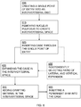
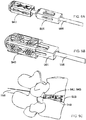
- the systems can include a cannula for inserting the scaffolding system into the intervertebral space; and, a guidewire adapted for guiding the central beam into the laterovertically expanding frame.
- An axis that is at least substantially parallel to another axis refers to an orientation that is intended, for all practical purposes to be parallel, but it is understood that this is just a convenient reference and that there can be variations due to stresses internal to the system and imperfections in the devices and systems.
- the phrase "at least substantially on a...plane” refers to an orientation or movement that is intended, for all practical purposes to be on or near the plane as a convenient measure of the orientation or movement, but it is understood that this is just a convenient reference and that there can be variations due to stresses internal to the system and imperfections in the devices and systems.
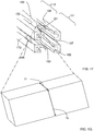
- the central beam 101 can also have a top surface 115 with a first top-lateral surface 117 and a second top-lateral surface 119, a bottom surface 120 with a first bottom-lateral surface 122 and a second bottom-lateral surface 124, a first side surface 125 with a first top-side surface 127 and a first bottom-side surface 129, and a second side surface 130 with a second top-side surface 132 and a second bottom-side surface 134.
- the frame is expanded at least "substantially" beyond the collapsed state when a bone graft window of the frame has opened by at least a 15%, 20%, 25%, 30%, 35%, 40%, 45%, 50%, 60%, 70%, 80%, 90%, 100%, 150%, 200%, 250%, 300%, or more when compared to the bone graft window from the collapsed state.
- the frame is expanded at least "substantially” beyond the collapsed state when a bone graft window of the frame has opened by at least 2x, 3x, 5x, 10x, 15x, 20x, or more when compared to the bone graft window from the collapsed state.
- the laterovertically expandable frames are created in an expanded state.
- the expanded state can include a state that is at least 30%, at least 40%, at least 50%, at least 60%, at least 70%, at least 80%, at least 90%, or at least 95% of the full expansion.
- full expansion can be used to refer to an extent of expansion upon which a connector element begins to fatigue, fail, or crack; or, in some embodiments, strain beyond 10%, 20%, or 30%.
- the frame 149 can be configured to have a second top beam 160 including a proximal portion 111 having an end, a grafting portion 112 having an end, and a distal portion (not shown) having an end, the second top beam 160 configured for contacting the second top-lateral surface 119 of the central beam 101 and the second top-side surface 132 of the central beam 101 in the expanded state 149e, the central axis of the second top beam at least substantially on (i) the top plane and (ii) a second side plane containing the central axis of the second top beam and the central axis of a second bottom beam.
- the frame 149 can be configured to have a plurality of distal top connector elements (not shown) configured to expandably connect the distal portion of the first top beam 150 to the distal portion of the second top beam 160, the expanding consisting of a flexing at least substantially on the top plane.
- the frame 149 can be configured to have a plurality of proximal first side connector elements 195 configured to expandably connect the proximal portion 111 of the first top beam 150 to the proximal portion 111 of the first bottom beam 170, the expanding consisting of a flexing at least substantially on a first side plane containing the central axis of the first top beam 150 and the central axis of the first bottom beam 170; a plurality of distal first side connector elements (not shown) configured to expandably connect the distal portion of the first top beam 150 to the distal portion of the first bottom beam 170, the expanding consisting of a flexing at least substantially on the first side plane.
- the central beam can have any one or any combination of graft port configurations that would be operable with the teachings provided herein.
- criteria for a suitable graft port configuration may include a combination of port size, number of ports, and placement of ports.
- the central beam can comprise a side graft port.
- the cages have the ability to at least (i) laterally expand within the intervertebral space to avoid backout of the device through the annulotomy, (ii) vertically expand for distraction of the intervertebral space, (iii) provide additional space within the device in the annulus for the introduction of graft materials; (iv) maintain a large, footprint to distribute load over a larger area against the endplate, for example, by not contracting in length to expand in height and/or width; and, (v) insert into the annulus in a minimally-invasive manner using only a unilateral approach.
- the cage has the gear component, for example, including the struts; and, the laterovertical expansion member is a shim device having the pawl component, for example, a projection that can angle toward the proximal end of the expansion member or away from the direction of insertion of the shim device.
- the cage has the pawl component, for example, including the struts; and, the laterovertical expansion member is a shim device having the gear component, for example, a series of projections.
- a projection can angle from about 5° to about 75° toward the proximal end of the expansion member or away from the direction of insertion of the shim device.
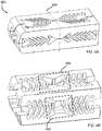
- each wall of the cage has a series of v-shaped struts 333 that (i) stack in a closed-complementary configuration 344 in the collapsed state to minimize void space in their respective wall for the low profile entry of the cage both vertically and laterally into the intervertebral space, and (ii) deflect upon expansion in a plane that is at least substantially parallel to the plane of their respective wall to an open-complementary configuration 355 to separate the at least 2 longitudinal beams of the total of 4 longitudinal beams 312,314,316,318 in the rectangular cylinder in their respective wall and open a bone graft window 366 to pass a bone graft material into the intervertebral space in the expanded configuration.
- the cage 300 is configured to accommodate the lateral dimension of the single point of entry ranging from about 5 mm to about 15
- This thickness can help maintain a high structural stiffness and strength in the direction perpendicular to the proximal-distal axis so that the transverse cross section (perpendicular to the proximal-distal axis) shape is maintained during and after insertion of the cage into the intervertebral disc space.
- the angle of each strut can range from about 140° -170° as measured at the vertex in the non-stressed state.
- the angle facilitates flexion of the legs of each strut towards each other upon moderate inward pressure to collapse the cage for insertion into the disc space.
- the angled strut lies in a plane at least substantially parallel to the plane of it's rcspcctivc wall, and in some embodiments to the long axis of the cage, so that the flexion does not alter the side wall thickness. This helps to maintain the low profile for insertion while maximizing the lumen size.
- FIGs. 5A-5D illustrate system for fusing an intervertebral disc space, according to some embodiments.
- the system 550 has a cage 555 having an expandable/collapsible bone graft window 566; a shim core 560 having a tapered nose 562 at the distal end of the shim core 560 and a bone graft window 566; a releasably attachable rail beam 565; a pusher (not shown) that slidably translates over the shim core 560 and the rail beam 565; a trial shim 575 having a shoulder 577 and slidably translating over the rail beam 565 and shim core 560 into the cage 555, and a permanent shim 580 having a shoulder 582 and slidably translating over the rail beam 565 and shim core 560 into the cage 555.
- the at least 4 walls form a cylinder having a long axis and include a top wall forming a top plane and having a top surface with protuberances adapted to contact the top vertebral plate; a bottom wall forming a bottom plane and having a bottom surface with protuberances adapted to contact the bottom vertebral plate; and, a first side wall forming a first side wall plane, and a second side wall forming a second side wall plane.
- Each of the walls can have at least 2 longitudinal beams and a plurality of struts.
- At least one of the walls can have a first series of v-shaped struts that are configured to stack in a closed-complementary configuration in the collapsed state to minimize void space for a low profile entry of the cage through a single point of entry into an intervertebral disc space; and, deflect upon expansion to an open-complementary configuration to separate the at least 2 longitudinal beams in their respective wall and open a bone graft window adapted to pass a bone graft material into the intervertebral space in the expanded configuration.
- the methods and systems provided herein include the use of bone graft materials known to one of skill.
- Materials which may be placed or injected into the intevertebral space include solid or semi-solid grafting materials, bone from removed from patient's facet, an iliac crest harvest from the patient, and bone graft extenders such as hydroxyapatite, demineralized bone matrix, and bone morphogenic protein.
- bone graft extenders such as hydroxyapatite, demineralized bone matrix, and bone morphogenic protein.
- solid or semi-solid grafting material components include solid fibrous collagen or other suitable hard hydrophilic biocompatible material. Some materials may also include swelling for further vertical expansion of the intervertebral disc space.
- FIGs. 11A and 11B compare an illustration of the graft distribution in place to a test placement in a cadaver to show relative size, according to some embodiments.
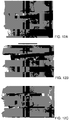
- FIGs. 12A-12C show x-rays of a placement in a cadaver, according to some embodiments.
- each of ⁇ T , ⁇ B , ⁇ FS , and ⁇ SS can be independently selected and each can be about 1°, 2°, 3°, 4°, 5°, 6°, 7°, 8°, 9°, 10°, 11°, 12°, 13°, 14°, 15°, 16°, 17°, 18°, 19°, 20°, 21°, 22°, 23°, 24°, 25°, 26°, 27°, 28°, 29°, 30°, 31°,32°, 33°, 34°, 35°, or any angle therein in increments of 0.1°.
- the framing can be configured for engaging with the central beam in vivo to support the framing in the expanded state.
- the connector elements can be struts configured to have a cross-sectional aspect ratio of longitudinal thickness to transverse thickness ranging from 1:2 to 1:8, adapted to maintain structural stiffness in the laterovertically expanding frame in a direction perpendicular to the central frame axis of the expanded state of the frame.
- each of the angles ⁇ 1T , ⁇ 1B , ⁇ 2T , ⁇ 2B can be independently selected from an amount of angulation ranging from about 15° to about 75°, from about 20° to about 75°, from about 25° to about 75°, from about 30° to about 75°, from about 35° to about 75°, from about 55° to about 75°, from about 15° to about 70°, from about 15° to about 65°, from about 15° to about 60°, from about 15° to about 55°, from about 15° to about 50°, from about 15° to about 45°, or any range therein.
- each of the angles ⁇ 1T , ⁇ 1B , ⁇ 2T , ⁇ 2B can be independently selected from an amount of angulation that is about 10°, about 15°, about 20°, about 25°, about 30°, about 35°, about 40°, about 45°, about 50°, about 55°, about 60°, about 65°, about 70°, about 75°, about 80°, or any angulation therein in amounts of 1°.
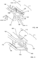
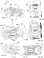
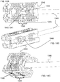
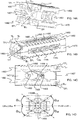
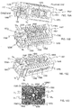
- the central beam 1501 has a horizontal groove HG configured complementary to the cross-member CM of the stabilizer 1507, and the horizontal groove HG of the central beam 1501 slidably connects with the cross-member CM in the expanded state.
- the cross-member CM further comprises a vertical support member VSM and the central beam 1501 has a vertical groove VG configured complementary to the vertical support member VSM of the stabilizer, and the vertical groove VG of the central beam 1501 slidably connects with the vertical support member VSM in the expanded state.
Landscapes
- Health & Medical Sciences (AREA)
- Engineering & Computer Science (AREA)
- Biomedical Technology (AREA)
- Orthopedic Medicine & Surgery (AREA)
- Neurology (AREA)
- Transplantation (AREA)
- Heart & Thoracic Surgery (AREA)
- Oral & Maxillofacial Surgery (AREA)
- Cardiology (AREA)
- Vascular Medicine (AREA)
- Life Sciences & Earth Sciences (AREA)
- Animal Behavior & Ethology (AREA)
- General Health & Medical Sciences (AREA)
- Public Health (AREA)
- Veterinary Medicine (AREA)
- Physical Education & Sports Medicine (AREA)
- Prostheses (AREA)
- Surgical Instruments (AREA)
Claims (15)
- Système d'échafaudage intervertébral, comprenant :une poutrelle centrale (101) présentant :un axe de poutrelle centrale (105) ;une partie proximale et une partie distale ;une surface de dessus (115) ayant une première surface latérale de dessus (117) et une deuxième surface latérale de dessus (119) ;une surface de fond (120) ayant une première surface latérale de fond (122) et une deuxième surface latérale de fond (124) ;une première surface de côté (125) ayant une première surface de dessus (127) et une première surface de fond (129) ; et,une deuxième surface de côté (130) ayant une deuxième surface de dessus (132) et une deuxième surface de fond (134) ;un cadre à expansion latéroverticale (149) configurée pour venir au contact de manière opérationnelle avec la poutrelle centrale (101) pour créer un système d'échafaudage intervertébral in vivo, le cadre (149) présentant :un état replié (149c) et un état déployé (149e), l'état déployé (149e) venant au contact de manière opérationnelle avec la poutrelle centrale (101) au niveau de l'espace intervertébral ;une partie proximale présentant une extrémité, une partie distale présentant une extrémité, et un axe de cadre central (113) à l'état déployé (149e) ;une première poutrelle de dessus (150) comportant une partie proximale présentant une extrémité et une partie distale présentant une extrémité, la première poutrelle de dessus (150) étant configurée pour venir au contact avec la première surface latérale de dessus (117) de la poutrelle centrale (101) et la première surface de côté de dessus (127) de la poutrelle centrale (101) à l'état déployé (149e), un axe central de la première poutrelle de dessus (150) étant situé sur (i) un plan de dessus contenant l'axe central de la première poutrelle de dessus(150) et un axe central d'une deuxième poutrelle de dessus (160) et (ii) un premier plan de côté contenant l'axe central de la première poutrelle de dessus (150) et un axe central d'une première poutrelle de fond (170) ;la deuxième poutrelle de dessus (160) comportant une partie proximale présentant une extrémité et une partie distale présentant une extrémité, la deuxième poutrelle de dessus (160) étant configurée pour venir au contact avec la deuxième surface latérale de dessus (119) de la poutrelle centrale (101) et la deuxième surface de côté de dessus (132) de la poutrelle centrale (101) à l'état déployé (149e), l'axe central de la deuxième poutrelle de dessus (160) étant situé au moins sensiblement sur (i) le plan de dessus et (ii) un deuxième plan de côté contenant l'axe central de la deuxième poutrelle de dessus (160) et un axe central d'une deuxième poutrelle de fond (180) ;la première poutrelle de fond (170) comportant une partie proximale présentant une extrémité et une partie distale présentant une extrémité, la première poutrelle de fond (170) étant configurée pour venir au contact avec la première surface latérale de fond (122) de la poutrelle centrale (101) et la première surface de côté de fond (129) de la poutrelle centrale (101) à l'état déployé (149e), l'axe central de la première poutrelle de fond (170) étant situé au moins sensiblement sur (i) un plan de fond contenant l'axe central de la première poutrelle de fond et l'axe central de la deuxième poutrelle de dessus (160) et (ii) le premier plan de côté ;la deuxième poutrelle de fond (180) comportant une partie proximale présentant une extrémité et une région distale présentant une extrémité, la deuxième poutrelle de fond (180) étant configurée pour venir au contact avec la deuxième surface latérale de fond (124) de la poutrelle centrale (101) et la deuxième surface de côté de fond (134) de la poutrelle centrale (101) à l'état déployé (149e), l'axe central de la deuxième poutrelle de fond (180) étant situé au moins sensiblement sur (i) le plan de fond et (ii) un deuxième plan de côté contenant l'axe central de la deuxième poutrelle de fond (180) et l'axe central de la deuxième poutrelle de dessus (160) ;une pluralité d'éléments connecteurs de dessus (191) configurés pour connecter de manière expansible la première poutrelle de dessus (150) à la deuxième poutrelle de dessus (160), l'expansion consistant en une flexion au moins sensiblement au niveau du plan de dessus ;une pluralité d'éléments connecteurs de fond (193) configurés pour connecter de manière expansible la première poutrelle de fond (170) à la deuxième poutrelle de fond (180), l'expansion consistant en une flexion au moins sensiblement au niveau du plan de fond ;une pluralité d'éléments connecteurs de côté (195) configurés pour connecter de manière expansible la première poutrelle de dessus (150) à la première poutrelle de fond (170), l'expansion consistant en une flexion au moins sensiblement au niveau du premier plan de côté ;une pluralité d'éléments connecteurs d'un deuxième côté (197) configurés pour connecter de manière expansible la deuxième poutrelle de dessus (160) à la deuxième poutrelle de fond (180), l'expansion consistant en une flexion au moins sensiblement au niveau du deuxième plan de côté ;et,un stabilisateur (1407, 1507) qui s'engage par coulissement avec la région distale de la première poutrelle de dessus (150), la première poutrelle de fond (170), la deuxième poutrelle de dessus (160), la deuxième poutrelle de fond (180), ou une combinaison de celles-ci, et qui est configuré pour retenir la première poutrelle de dessus(150), la première poutrelle de fond (170), la deuxième poutrelle de dessus (160), la deuxième poutrelle de fond (180), ou une combinaison de celles-ci, contre tout mouvement latéral dépassant l'état déployé ;selon lequel,le cadre est configuré pour s'engager avec la poutrelle centrale (101) in vivo afin de soutenir le cadre à l'état déployé (149e) ; et,les éléments connecteurs sont des entretoises adaptées à maintenir une rigidité structurelle dans le cadre à expansion latéroverticale (149) selon une direction perpendiculaire à l'axe du cadre central (113) à l'état déployé (149e) du cadre (149).
- Système d'échafaudage selon la revendication 1, selon lequel le stabilisateur (1407, 1507) se présente sous forme d'une configuration en X présentant une première patte de dessus pour s'engager par coulissement avec la première poutrelle de dessus (150) à un angle de θ1T par rapport au mouvement latéral de la première poutrelle de dessus (150), une première patte de fond pour s'engager par coulissement avec la première poutrelle de fond (170) à un angle de θ1B par rapport au mouvement latéral de la première poutrelle de fond(170), une deuxième patte de dessus pour s'engager en coulissement avec la deuxième poutrelle de dessus (160) à un angle de θ2T par rapport au mouvement latéral de la deuxième poutrelle de dessus (160), et une deuxième patte de fond pour s'engager par coulissement avec la deuxième poutrelle de fond (180) à un angle de θ2b par rapport au mouvement latéral de la deuxième patte de fond (180), selon lequel chacun des angles θ1T, θ1B, θ2T, θ2B, respectivement, fournit un effort de traction pour faire résistance à la première poutrelle de dessus (150), la première poutrelle de fond (170), la deuxième poutrelle de dessus (160), et la deuxième poutrelle de fond (180) contre tout mouvement latéral dépassant l'état déployé (149e).
- Système d'échafaudage selon la revendication 1, selon lequel le stabilisateur (1407, 1507) se présente sous forme d'une configuration en X présentant une première patte de dessus pour s'engager par coulissement avec la première poutrelle de dessus (150) à un angle de θ1T par rapport au mouvement latéral de la première poutrelle de dessus (150), une première patte de fond pour s'engager par coulissement avec la première poutrelle de fond (170) à un angle de θ1B par rapport au mouvement latéral de la première poutrelle de fond (170), une deuxième patte de dessus pour s'engager en coulissement avec la deuxième poutrelle de dessus (160) à un angle de θ2T par rapport au mouvement latéral de la deuxième poutrelle de dessus (160), et une deuxième patte de fond pour s'engager par coulissement avec la deuxième poutrelle de fond (180) à un angle de θ2B par rapport au mouvement latéral de la deuxième patte de fond (180), selon lequel chacun des angles θ1T, θ1B, θ2T, θ2B, respectivement, fournit un effort de traction pour faire résistance à la première poutrelle de dessus (150), la première poutrelle de fond (170), la deuxième poutrelle de dessus (160), et la deuxième poutrelle de fond (180) contre tout mouvement latéral dépassant l'état déployé (149e) ;
selon lequel le stabilisateur (1407, 1507) comprend en outre un point de fixation (1408) pour fixer de manière libérable un fil-guide pour le guidage de la poutrelle centrale (101) dans le cadre à expansion latéroverticale (149e). - Système d'échafaudage selon la revendication 1, selon lequel le stabilisateur (1407, 1507) se présente sous forme d'une configuration en X présentant une première patte de dessus pour s'engager par coulissement avec la première poutrelle de dessus (150) à un angle de θ1T par rapport au mouvement latéral de la première poutrelle de dessus (150), une première patte de fond pour s'engager par coulissement avec la première poutrelle de fond (170) à un angle de θ1B par rapport au mouvement latéral de la première poutrelle de fond (170), une deuxième patte de dessus pour s'engager en coulissement avec la deuxième poutrelle de dessus (160) à un angle de θ2T par rapport au mouvement latéral de la deuxième poutrelle de dessus (160), et une deuxième patte de fond pour s'engager par coulissement avec la deuxième poutrelle de fond (180) à un angle de θ2B par rapport au mouvement latéral de la deuxième patte de fond (180), selon lequel chacun des angles θ1T, θ1B, θ2T, θ2B, respectivement, fournit un effort de traction pour faire résistance à la première poutrelle de dessus (150), la première poutrelle de fond (170), la deuxième poutrelle de dessus (160), et la deuxième poutrelle de fond (180) contre tout mouvement latéral dépassant l'état déployé (149e) ;
selon lequel la première patte de dessus, la première patte de fond, la deuxième patte de dessus et la deuxième patte de fond convergent pour former un moyeu (1408H) présentant un point de fixation (1408) d'un fil-guide libérable pour le guidage de la poutrelle centrale (101) dans le cadre à expansion latéroverticale (149) . - Système d'échafaudage selon la revendication 1, selon lequel le stabilisateur (1407, 1507) se présente sous forme d'une configuration en H présentant une première patte verticale, une deuxième patte verticale et un élément transversal qui connecte la première patte verticale de manière sensiblement parallèle à la deuxième patte verticale, la première patte verticale comportant une surface de rétention pour s'engager avec la première poutrelle de dessus (150) et la première poutrelle de fond (170), la deuxième patte verticale comportant une surface de rétention pour s'engager avec la deuxième poutrelle de dessus (160) et la deuxième poutrelle de fond (180), et l'élément transversal fournit un effort de traction pour faire résistance à la première poutrelle de dessus (150), la première poutrelle de fond (170), la deuxième poutrelle de dessus (160), et la deuxième poutrelle de fond (180) contre tout mouvement latéral dépassant l'état déployé (149e) .
- Système d'échafaudage selon la revendication 1, selon lequel le stabilisateur (1407, 1507) se présente sous forme d'une configuration en H présentant une première patte verticale, une deuxième patte verticale et un élément transversal qui connecte la première patte verticale de manière sensiblement parallèle à la deuxième patte verticale, la première patte verticale comportant une surface de rétention pour s'engager avec la première poutrelle de dessus (150) et la première poutrelle de fond (170), la deuxième patte verticale comportant une surface de rétention pour s'engager avec la deuxième poutrelle de dessus (160) et la deuxième poutrelle de fond (180), et l'élément transversal fournit un effort de traction pour faire résistance à la première poutrelle de dessus (150), la première poutrelle de fond (170), la deuxième poutrelle de dessus (160), et la deuxième poutrelle de fond (180) contre tout mouvement latéral dépassant l'état déployé (149e) ;
selon lequel la poutrelle centrale (101) présente une rainure horizontale configurée de manière complémentaire à l'élément transversal du stabilisateur (1407, 1507), et la rainure horizontale de la poutrelle centrale (101) connecte de manière coulissante avec l'élément transversal à l'état déployé (149e). - Système d'échafaudage selon la revendication 1, selon lequel le stabilisateur (1407, 1507) se présente sous forme d'une configuration en H présentant une première patte verticale, une deuxième patte verticale et un élément transversal qui connecte la première patte verticale de manière sensiblement parallèle à la deuxième patte verticale, la première patte verticale comportant une surface de rétention pour s'engager avec la première poutrelle de dessus (150) et la première poutrelle de fond (170), la deuxième patte verticale comportant une surface de rétention pour s'engager avec la deuxième poutrelle de dessus (160) et la deuxième poutrelle de fond (180), et l'élément transversal fournit un effort de traction pour faire résistance à la première poutrelle de dessus (150), la première poutrelle de fond (170), la deuxième poutrelle de dessus (160), et la deuxième poutrelle de fond (180) contre tout mouvement latéral dépassant l'état déployé (149e) ;
selon lequel l'élément transversal comprend en outre un élément de support vertical et la poutrelle centrale (101) présente une rainure verticale configurée de manière complémentaire à l'élément de support vertical du stabilisateur (1407, 1507), et la rainure verticale de la poutrelle centrale (101) vient au contact de manière coulissante avec l'élément de support vertical à l'état déployé (149e). - Système d'échafaudage selon la revendication 1, selon lequel le stabilisateur (1407, 1507) se présente sous forme d'une configuration en H présentant une première patte verticale, une deuxième patte verticale et un élément transversal qui connecte la première patte verticale de manière sensiblement parallèle à la deuxième patte verticale, la première patte verticale comportant une surface de rétention pour s'engager avec la première poutrelle de dessus (150) et la première poutrelle de fond (170), la deuxième patte verticale comportant une surface de rétention pour s'engager avec la deuxième poutrelle de dessus (160) et la deuxième poutrelle de fond (180), et l'élément transversal fournit un effort de traction pour faire résistance à la première poutrelle de dessus (150), la première poutrelle de fond (170), la deuxième poutrelle de dessus (160), et la deuxième poutrelle de fond (180) contre tout mouvement latéral dépassant l'état déployé (149e) ;
selon lequel le stabilisateur (1407, 1507) comprend en outre un point de fixation (1408) pour fixer de manière libérable un fil-guide adapté au guidage de la poutrelle centrale (101) dans le cadre à expansion latéroverticale (149). - Système d'échafaudage selon la revendication 1, selon lequel le stabilisateur (1407, 1507) se présente sous forme d'une configuration en H présentant une première patte verticale, une deuxième patte verticale et un élément transversal qui connecte la première patte verticale de manière sensiblement parallèle à la deuxième patte verticale, la première patte verticale comportant une surface de rétention pour s'engager avec la première poutrelle de dessus (150) et la première poutrelle de fond (170), la deuxième patte verticale comportant une surface de rétention pour s'engager avec la deuxième poutrelle de dessus (160) et la deuxième poutrelle de fond (180), et l'élément transversal fournit un effort de traction pour faire résistance à la première poutrelle de dessus (150), la première poutrelle de fond (170), la deuxième poutrelle de dessus (160), et la deuxième poutrelle de fond (180) contre tout mouvement latéral dépassant l'état déployé (149e) ;
selon lequel l'élément transversal comporte un premier pilier et un deuxième pilier qui se connectent de manière opérationnelle au niveau d'un moyeu (1408H) présentant un point de fixation (1408) pour la fixation libérable d'un fil-guide pour le guidage de la poutrelle centrale (101) dans le cadre à expansion latéroverticale (149). - Système d'échafaudage selon la revendication 1, la poutrelle centrale (101) comprenant en outre un orifice de greffage.
- Système d'échafaudage selon la revendication 1, selon lequel chaque pluralité d'éléments connecteurs est des entretoises ; selon lequel,
les entretoises de dessus sont configurées de manière intégrale monolithique à la première poutrelle de dessus (150) et à la deuxième poutrelle de dessus (160) ; et,
les entretoises de fond sont configurées de manière intégrale monolithique à la première poutrelle de fond (170) et à la deuxième poutrelle de fond (180) ;
selon lequel les entretoises de dessus et les entretoises de fond du cadre à expansion latéroverticale (149) sont chacune configurées pour ouvrir une fenêtre de distribution de greffe lors de l'expansion, s'expansant depuis la première poutrelle de dessus (150) en direction de la deuxième poutrelle de dessus (160), depuis la première poutrelle de dessus (150) en direction de la première poutrelle de fond (170), depuis la deuxième poutrelle de dessus (160) en direction de la deuxième poutrelle de fond (180), ou depuis la première poutrelle de fond (170) en direction de la deuxième poutrelle de fond (180). - Système d'échafaudage selon la revendication 1, selon lequel :les entretoises de connexion de dessus sont configurées de manière intégrale monolithique à la première poutrelle de dessus (150) et à la deuxième poutrelle de dessus (160) ; et,les entretoises de fond sont configurées de manière intégrale monolithique à la première poutrelle de fond (170) et à la deuxième poutrelle de fond (180) ;les premières entretoises de côté sont configurées de manière intégrale monolithique à la première poutrelle de dessus (150) et à la première poutrelle de fond(170) ; et,les deuxièmes entretoises de côté sont configurées de manière intégrale monolithique à la deuxième poutrelle de dessus (160) et à la deuxième poutrelle de fond (180) ;selon lequel le dessus, fond, premier côté, et deuxième côté du cadre à expansion latéroverticale (149) forment un cadre intégré monolithique.
- Système d'échafaudage selon la revendication 1, selon lequel les entretoises présentent un rapport d'aspect de section transversale d'épaisseur longitudinale par rapport à l'épaisseur transversale s'étendant de 1:2 à 1:8.
- Ensemble comprenant :le système d'échafaudage selon la revendication 1 ;une canule pour l'insertion du système d'échafaudage dans l'espace intervertébral ; et,un fil-guide adapté au guidage de la poutrelle centrale (101) dans le cadre à expansion latéroverticale (149).
- Ensemble comprenant :le système d'échafaudage selon la revendication 6 ;une canule pour l'insertion du système d'échafaudage dans l'espace intervertébral ; et,un fil-guide adapté au guidage de la poutrelle centrale (101) dans le cadre à expansion latéroverticale (149).
Applications Claiming Priority (2)
| Application Number | Priority Date | Filing Date | Title |
|---|---|---|---|
| US14/600,617 US9060876B1 (en) | 2015-01-20 | 2015-01-20 | Stabilized intervertebral scaffolding systems |
| PCT/US2016/014100 WO2016118608A1 (fr) | 2015-01-20 | 2016-01-20 | Systèmes d'échafaudages intervertébraux stabilisés |
Publications (3)
| Publication Number | Publication Date |
|---|---|
| EP3247315A1 EP3247315A1 (fr) | 2017-11-29 |
| EP3247315A4 EP3247315A4 (fr) | 2018-09-05 |
| EP3247315B1 true EP3247315B1 (fr) | 2021-05-12 |
Family
ID=53396986
Family Applications (1)
| Application Number | Title | Priority Date | Filing Date |
|---|---|---|---|
| EP16740662.8A Active EP3247315B1 (fr) | 2015-01-20 | 2016-01-20 | Systèmes d'échafaudages intervertébraux stabilisés |
Country Status (6)
| Country | Link |
|---|---|
| US (6) | US9060876B1 (fr) |
| EP (1) | EP3247315B1 (fr) |
| JP (1) | JP2018501942A (fr) |
| CN (1) | CN107427371B (fr) |
| AU (1) | AU2016209382B2 (fr) |
| WO (1) | WO2016118608A1 (fr) |
Families Citing this family (116)
| Publication number | Priority date | Publication date | Assignee | Title |
|---|---|---|---|---|
| US6793678B2 (en) | 2002-06-27 | 2004-09-21 | Depuy Acromed, Inc. | Prosthetic intervertebral motion disc having dampening |
| US20180228621A1 (en) | 2004-08-09 | 2018-08-16 | Mark A. Reiley | Apparatus, systems, and methods for the fixation or fusion of bone |
| US9949843B2 (en) | 2004-08-09 | 2018-04-24 | Si-Bone Inc. | Apparatus, systems, and methods for the fixation or fusion of bone |
| WO2008070863A2 (fr) | 2006-12-07 | 2008-06-12 | Interventional Spine, Inc. | Implant intervertébral |
| US8900307B2 (en) | 2007-06-26 | 2014-12-02 | DePuy Synthes Products, LLC | Highly lordosed fusion cage |
| AU2009205896A1 (en) | 2008-01-17 | 2009-07-23 | Synthes Gmbh | An expandable intervertebral implant and associated method of manufacturing the same |
| US12232975B2 (en) * | 2008-02-22 | 2025-02-25 | Howmedica Osteonics Corp. | Lockable spinal implant |
| AU2009231637A1 (en) | 2008-04-05 | 2009-10-08 | Synthes Gmbh | Expandable intervertebral implant |
| US9526620B2 (en) | 2009-03-30 | 2016-12-27 | DePuy Synthes Products, Inc. | Zero profile spinal fusion cage |
| CN105342683B (zh) | 2009-07-06 | 2018-02-13 | 斯恩蒂斯有限公司 | 可膨胀固定组件 |
| US8979860B2 (en) | 2010-06-24 | 2015-03-17 | DePuy Synthes Products. LLC | Enhanced cage insertion device |
| AU2011271465B2 (en) | 2010-06-29 | 2015-03-19 | Synthes Gmbh | Distractible intervertebral implant |
| US20120078372A1 (en) | 2010-09-23 | 2012-03-29 | Thomas Gamache | Novel implant inserter having a laterally-extending dovetail engagement feature |
| US9402732B2 (en) | 2010-10-11 | 2016-08-02 | DePuy Synthes Products, Inc. | Expandable interspinous process spacer implant |
| US9248028B2 (en) | 2011-09-16 | 2016-02-02 | DePuy Synthes Products, Inc. | Removable, bone-securing cover plate for intervertebral fusion cage |
| US9820788B2 (en) | 2011-10-05 | 2017-11-21 | H. Lee Moffitt Cancer Center And Research Institute, Inc. | Bone fusion system |
| US10363140B2 (en) | 2012-03-09 | 2019-07-30 | Si-Bone Inc. | Systems, device, and methods for joint fusion |
| US8940052B2 (en) | 2012-07-26 | 2015-01-27 | DePuy Synthes Products, LLC | Expandable implant |
| US8663332B1 (en) | 2012-12-13 | 2014-03-04 | Ouroboros Medical, Inc. | Bone graft distribution system |
| US9717601B2 (en) | 2013-02-28 | 2017-08-01 | DePuy Synthes Products, Inc. | Expandable intervertebral implant, system, kit and method |
| US9522070B2 (en) | 2013-03-07 | 2016-12-20 | Interventional Spine, Inc. | Intervertebral implant |
| US10426632B2 (en) | 2013-03-13 | 2019-10-01 | Life Spine, Inc. | Expandable spinal interbody assembly |
| US12193948B2 (en) | 2013-03-13 | 2025-01-14 | Life Spine, Inc. | Expandable implant assembly |
| US9186259B2 (en) | 2013-09-09 | 2015-11-17 | Ouroboros Medical, Inc. | Expandable trials |
| US11147688B2 (en) | 2013-10-15 | 2021-10-19 | Si-Bone Inc. | Implant placement |
| US10166033B2 (en) | 2014-09-18 | 2019-01-01 | Si-Bone Inc. | Implants for bone fixation or fusion |
| US9662157B2 (en) * | 2014-09-18 | 2017-05-30 | Si-Bone Inc. | Matrix implant |
| AU2016200179B2 (en) | 2015-01-14 | 2020-09-17 | Stryker European Operations Holdings Llc | Spinal implant with porous and solid surfaces |
| CA2917503A1 (fr) | 2015-01-14 | 2016-07-14 | Stryker European Holdings I, Llc | Implant vertebral dote de capacites de distribution de fluide |
| US9060876B1 (en) * | 2015-01-20 | 2015-06-23 | Ouroboros Medical, Inc. | Stabilized intervertebral scaffolding systems |
| US11426290B2 (en) | 2015-03-06 | 2022-08-30 | DePuy Synthes Products, Inc. | Expandable intervertebral implant, system, kit and method |
| US10376206B2 (en) | 2015-04-01 | 2019-08-13 | Si-Bone Inc. | Neuromonitoring systems and methods for bone fixation or fusion procedures |
| US10709570B2 (en) | 2015-04-29 | 2020-07-14 | Institute for Musculoskeletal Science and Education, Ltd. | Implant with a diagonal insertion axis |
| US10492921B2 (en) | 2015-04-29 | 2019-12-03 | Institute for Musculoskeletal Science and Education, Ltd. | Implant with arched bone contacting elements |
| EP3288501B1 (fr) | 2015-04-29 | 2020-11-25 | Institute For Musculoskeletal Science And Education, Ltd. | Implants helicoidaux |
| US10449051B2 (en) | 2015-04-29 | 2019-10-22 | Institute for Musculoskeletal Science and Education, Ltd. | Implant with curved bone contacting elements |
| CA2930123A1 (fr) | 2015-05-18 | 2016-11-18 | Stryker European Holdings I, Llc | Implants partiellement resorbables et methodes |
| US9913727B2 (en) | 2015-07-02 | 2018-03-13 | Medos International Sarl | Expandable implant |
| KR101674490B1 (ko) * | 2015-07-10 | 2016-11-09 | 주식회사 메드릭스 | 최소 침습 수술용 공간 확장형 케이지 장치 |
| US9713536B2 (en) * | 2015-08-12 | 2017-07-25 | Warsaw Orthopedic, Inc. | Expandable spinal implant and method of implanting same |
| US10105238B2 (en) * | 2015-08-25 | 2018-10-23 | Imds Llc | Expandable intervertebral implants |
| EP3228283B1 (fr) * | 2016-04-07 | 2023-10-25 | Howmedica Osteonics Corp. | Instruments d'insertion chirurgicale |
| EP4233801B1 (fr) | 2016-06-28 | 2025-11-05 | Eit Emerging Implant Technologies GmbH | Cages intervertébrales à expansion et réglage angulaire |
| US11596522B2 (en) | 2016-06-28 | 2023-03-07 | Eit Emerging Implant Technologies Gmbh | Expandable and angularly adjustable intervertebral cages with articulating joint |
| US9883953B1 (en) * | 2016-09-21 | 2018-02-06 | Integrity Implants Inc. | Stabilized laterovertically-expanding fusion cage systems with tensioner |
| US11033394B2 (en) | 2016-10-25 | 2021-06-15 | Institute for Musculoskeletal Science and Education, Ltd. | Implant with multi-layer bone interfacing lattice |
| WO2018081322A1 (fr) | 2016-10-25 | 2018-05-03 | Imds Llc | Méthodes et instruments d'extension de cage intervertébrale |
| US10478312B2 (en) | 2016-10-25 | 2019-11-19 | Institute for Musculoskeletal Science and Education, Ltd. | Implant with protected fusion zones |
| FR3058044A1 (fr) * | 2016-10-27 | 2018-05-04 | Ldr Medical | Cage intersomatique expansible |
| FR3058043B1 (fr) * | 2016-10-27 | 2020-11-13 | Ldr Medical | Cage intersomatique expansible |
| US10537436B2 (en) | 2016-11-01 | 2020-01-21 | DePuy Synthes Products, Inc. | Curved expandable cage |
| US10888433B2 (en) | 2016-12-14 | 2021-01-12 | DePuy Synthes Products, Inc. | Intervertebral implant inserter and related methods |
| EP4623870A3 (fr) | 2017-01-10 | 2025-12-24 | Integrity Implants Inc. | Dispositif de fusion intervertébrale extensible |
| US10512549B2 (en) | 2017-03-13 | 2019-12-24 | Institute for Musculoskeletal Science and Education, Ltd. | Implant with structural members arranged around a ring |
| US10213317B2 (en) | 2017-03-13 | 2019-02-26 | Institute for Musculoskeletal Science and Education | Implant with supported helical members |
| US10357377B2 (en) | 2017-03-13 | 2019-07-23 | Institute for Musculoskeletal Science and Education, Ltd. | Implant with bone contacting elements having helical and undulating planar geometries |
| US10667924B2 (en) | 2017-03-13 | 2020-06-02 | Institute for Musculoskeletal Science and Education, Ltd. | Corpectomy implant |
| US10398563B2 (en) | 2017-05-08 | 2019-09-03 | Medos International Sarl | Expandable cage |
| US11344424B2 (en) | 2017-06-14 | 2022-05-31 | Medos International Sarl | Expandable intervertebral implant and related methods |
| US10940016B2 (en) | 2017-07-05 | 2021-03-09 | Medos International Sarl | Expandable intervertebral fusion cage |
| US11896494B2 (en) | 2017-07-10 | 2024-02-13 | Life Spine, Inc. | Expandable implant assembly |
| WO2019023251A1 (fr) * | 2017-07-24 | 2019-01-31 | Integrity Implants, Inc. | Implant chirurgical et procédés associés |
| US10709578B2 (en) | 2017-08-25 | 2020-07-14 | Integrity Implants Inc. | Surgical biologics delivery system and related methods |
| EP3456297B1 (fr) | 2017-09-15 | 2023-10-04 | Howmedica Osteonics Corp. | Instruments pour implants intercorporels extensibles |
| EP3459502B1 (fr) | 2017-09-20 | 2024-05-22 | Stryker European Operations Holdings LLC | Implants vertébraux |
| US11116519B2 (en) | 2017-09-26 | 2021-09-14 | Si-Bone Inc. | Systems and methods for decorticating the sacroiliac joint |
| US10893945B2 (en) | 2017-09-29 | 2021-01-19 | Luis E Duarte | Bone cage including offset sets of protrusions within a bone ingrowth cavity and related methods |
| US10744001B2 (en) | 2017-11-21 | 2020-08-18 | Institute for Musculoskeletal Science and Education, Ltd. | Implant with improved bone contact |
| US10940015B2 (en) | 2017-11-21 | 2021-03-09 | Institute for Musculoskeletal Science and Education, Ltd. | Implant with improved flow characteristics |
| US10945859B2 (en) | 2018-01-29 | 2021-03-16 | Amplify Surgical, Inc. | Expanding fusion cages |
| US10695192B2 (en) | 2018-01-31 | 2020-06-30 | Institute for Musculoskeletal Science and Education, Ltd. | Implant with internal support members |
| EP3742990B1 (fr) | 2018-03-01 | 2026-02-11 | Integrity Implants Inc. | Dispositif de fusion expansible doté de systèmes d'expansion indépendants |
| EP3773281B1 (fr) | 2018-03-28 | 2025-01-08 | SI-Bone, Inc. | Implants filetés pour utilisation à travers des segments osseux |
| WO2020033600A1 (fr) * | 2018-08-07 | 2020-02-13 | Minimally Invasive Spinal Technology, LLC | Dispositif et procédé de correction de déformations rachidiennes chez des patients |
| US11446156B2 (en) | 2018-10-25 | 2022-09-20 | Medos International Sarl | Expandable intervertebral implant, inserter instrument, and related methods |
| GB201818847D0 (en) | 2018-11-19 | 2019-01-02 | Axis Spine Tech Ltd | Intervertebral devices |
| GB201818850D0 (en) | 2018-11-19 | 2019-01-02 | Axis Spine Tech Ltd | Intervertebral devices |
| GB201902002D0 (en) | 2019-02-13 | 2019-04-03 | Axis Spine Tech Ltd | Intervertebral devices |
| GB201818849D0 (en) | 2018-11-19 | 2019-01-02 | Axis Spine Tech Ltd | Intervertebral devices |
| US10722380B1 (en) * | 2019-02-04 | 2020-07-28 | Bret Michael Berry | Laterally expandable spinal implant |
| WO2020168269A1 (fr) | 2019-02-14 | 2020-08-20 | Si-Bone Inc. | Implants de fixation et/ou de fusion vertébrale |
| US11369419B2 (en) | 2019-02-14 | 2022-06-28 | Si-Bone Inc. | Implants for spinal fixation and or fusion |
| US11173043B1 (en) * | 2019-05-17 | 2021-11-16 | Joseph T. Robbins | Spinal interbody implants |
| EP3979951A1 (fr) | 2019-06-10 | 2022-04-13 | Life Spine, Inc. | Ensemble implant expansible présentant des propriétés de compression |
| US12042395B2 (en) | 2019-06-11 | 2024-07-23 | Life Spine, Inc. | Expandable implant assembly |
| GB201910640D0 (en) | 2019-07-25 | 2019-09-11 | Axis Spine Tech Ltd | Insertions instruments |
| GB201910668D0 (en) | 2019-07-25 | 2019-09-11 | Axis Spine Tech Ltd | Assemblies for and methods of determing height and angle of an intervertebral device |
| AU2020334921B2 (en) | 2019-08-21 | 2026-01-08 | FloSpine, LLC | Interspinous-interlaminar stabilization systems and methods |
| GB201913778D0 (en) | 2019-09-24 | 2019-11-06 | Axis Spine Tech Ltd | Intervertebral devices |
| WO2021092948A1 (fr) * | 2019-11-15 | 2021-05-20 | 邹丽敏 | Cages de fusion intersomatique |
| AU2020386985A1 (en) | 2019-11-21 | 2022-06-02 | Si-Bone Inc. | Rod coupling assemblies for bone stabilization constructs |
| ES3042147T3 (en) | 2019-11-27 | 2025-11-18 | Si Bone Inc | Bone stabilizing implants across si joints |
| JP2023504571A (ja) | 2019-12-09 | 2023-02-03 | エスアイ-ボーン・インコーポレイテッド | 仙腸関節安定化インプラント及び埋込方法 |
| US12042393B2 (en) | 2019-12-19 | 2024-07-23 | FloSpine, LLC | Expandable inter vertebral implant |
| WO2021179011A1 (fr) | 2020-03-05 | 2021-09-10 | Orchid Mps Holdings, Llc | Cage vertébrale extensible verticalement et latéralement |
| US11426286B2 (en) | 2020-03-06 | 2022-08-30 | Eit Emerging Implant Technologies Gmbh | Expandable intervertebral implant |
| US11857432B2 (en) | 2020-04-13 | 2024-01-02 | Life Spine, Inc. | Expandable implant assembly |
| US11602439B2 (en) | 2020-04-16 | 2023-03-14 | Life Spine, Inc. | Expandable implant assembly |
| US12336917B2 (en) | 2020-05-15 | 2025-06-24 | Life Spine, Inc. | Steerable implant assembly |
| US11602440B2 (en) | 2020-06-25 | 2023-03-14 | Life Spine, Inc. | Expandable implant assembly |
| US12329652B2 (en) | 2020-07-20 | 2025-06-17 | Integrity Implants Inc. | Expandable fusion device with independent expansion systems |
| US12036129B2 (en) * | 2020-08-13 | 2024-07-16 | Brigham Young University | Deployable compliant mechanism |
| US11554020B2 (en) | 2020-09-08 | 2023-01-17 | Life Spine, Inc. | Expandable implant with pivoting control assembly |
| JP2023553120A (ja) | 2020-12-09 | 2023-12-20 | エスアイ-ボーン・インコーポレイテッド | 仙腸関節安定化インプラントおよびインプラント方法 |
| US12533240B2 (en) | 2021-03-10 | 2026-01-27 | Amplify Surgical, Inc. | Drive instruments with retention mechanisms, medical implants, and related technologies |
| US11850160B2 (en) | 2021-03-26 | 2023-12-26 | Medos International Sarl | Expandable lordotic intervertebral fusion cage |
| US11752009B2 (en) | 2021-04-06 | 2023-09-12 | Medos International Sarl | Expandable intervertebral fusion cage |
| US12453640B2 (en) | 2021-07-16 | 2025-10-28 | Blue Ocean Spine Gmbh | Adjustable spinal implants, associated instruments and methods |
| US12318307B2 (en) | 2021-07-16 | 2025-06-03 | Blue Ocean Spine Gmbh | Adjustable spinal implants, associated instruments and methods |
| WO2023102533A1 (fr) | 2021-12-03 | 2023-06-08 | Si-Bone Inc. | Cages intersomatique et procédés de stabilisation d'articulation sacro-iliaque |
| US12090064B2 (en) | 2022-03-01 | 2024-09-17 | Medos International Sarl | Stabilization members for expandable intervertebral implants, and related systems and methods |
| US20240033100A1 (en) * | 2022-07-29 | 2024-02-01 | Warsaw Orthopedic, Inc. | Interbody implant having endplates connected by struts |
| US12533242B2 (en) | 2023-01-18 | 2026-01-27 | Blue Ocean Spine Gmbh | Adjustable spinal implants and related deployment instruments |
| WO2024173421A2 (fr) | 2023-02-13 | 2024-08-22 | FloSpine, LLC | Systèmes et procédés de stabilisation interépineuse-interlaminaire |
| WO2024217848A1 (fr) * | 2023-04-18 | 2024-10-24 | Medtronic Holding Company Sàrl | Implant vertébral extensible |
| AU2024325368A1 (en) | 2023-08-15 | 2026-03-12 | Si-Bone Inc. | Pelvic stabilization implants, methods of use and manufacture |
Family Cites Families (270)
| Publication number | Priority date | Publication date | Assignee | Title |
|---|---|---|---|---|
| US4309777A (en) | 1980-11-13 | 1982-01-12 | Patil Arun A | Artificial intervertebral disc |
| EP0176728B1 (fr) | 1984-09-04 | 1989-07-26 | Humboldt-Universität zu Berlin | Prothèse pour disques intervertébraux |
| US4733665C2 (en) | 1985-11-07 | 2002-01-29 | Expandable Grafts Partnership | Expandable intraluminal graft and method and apparatus for implanting an expandable intraluminal graft |
| DE3637314A1 (de) | 1986-11-03 | 1988-05-11 | Lutz Biedermann | Platzhalter-implantat |
| DE3809793A1 (de) | 1988-03-23 | 1989-10-05 | Link Waldemar Gmbh Co | Chirurgischer instrumentensatz |
| US5609635A (en) | 1988-06-28 | 1997-03-11 | Michelson; Gary K. | Lordotic interbody spinal fusion implants |
| US5221261A (en) | 1990-04-12 | 1993-06-22 | Schneider (Usa) Inc. | Radially expandable fixation member |
| US5192327A (en) | 1991-03-22 | 1993-03-09 | Brantigan John W | Surgical prosthetic implant for vertebrae |
| US5449373A (en) | 1994-03-17 | 1995-09-12 | Medinol Ltd. | Articulated stent |
| US5658336A (en) * | 1994-03-18 | 1997-08-19 | Pisharodi; Madhavan | Rotating, locking, middle-expanded intervertebral disk stabilizer |
| US5653762A (en) * | 1994-03-18 | 1997-08-05 | Pisharodi; Madhavan | Method of stabilizing adjacent vertebrae with rotating, lockable, middle-expanded intervertebral disk stabilizer |
| US5980522A (en) | 1994-07-22 | 1999-11-09 | Koros; Tibor | Expandable spinal implants |
| FR2753368B1 (fr) | 1996-09-13 | 1999-01-08 | Chauvin Jean Luc | Cage d'osteosynthese expansive |
| US5749916A (en) | 1997-01-21 | 1998-05-12 | Spinal Innovations | Fusion implant |
| DE69840774D1 (de) | 1997-02-06 | 2009-06-04 | Howmedica Osteonics Corp | Erweiterbare, gewindelose vorrichtung zur wirbelsäulenfusion |
| US6039761A (en) | 1997-02-12 | 2000-03-21 | Li Medical Technologies, Inc. | Intervertebral spacer and tool and method for emplacement thereof |
| IL128261A0 (en) | 1999-01-27 | 1999-11-30 | Disc O Tech Medical Tech Ltd | Expandable element |
| DE19807236C2 (de) | 1998-02-20 | 2000-06-21 | Biedermann Motech Gmbh | Zwischenwirbelimplantat |
| US6126689A (en) | 1998-06-15 | 2000-10-03 | Expanding Concepts, L.L.C. | Collapsible and expandable interbody fusion device |
| US6193757B1 (en) | 1998-10-29 | 2001-02-27 | Sdgi Holdings, Inc. | Expandable intervertebral spacers |
| US6102950A (en) | 1999-01-19 | 2000-08-15 | Vaccaro; Alex | Intervertebral body fusion device |
| US7621950B1 (en) | 1999-01-27 | 2009-11-24 | Kyphon Sarl | Expandable intervertebral spacer |
| US6491724B1 (en) | 1999-08-13 | 2002-12-10 | Bret Ferree | Spinal fusion cage with lordosis correction |
| US6419705B1 (en) | 1999-06-23 | 2002-07-16 | Sulzer Spine-Tech Inc. | Expandable fusion device and method |
| AU5701200A (en) | 1999-07-02 | 2001-01-22 | Petrus Besselink | Reinforced expandable cage |
| US6425919B1 (en) | 1999-08-18 | 2002-07-30 | Intrinsic Orthopedics, Inc. | Devices and methods of vertebral disc augmentation |
| US6821276B2 (en) | 1999-08-18 | 2004-11-23 | Intrinsic Therapeutics, Inc. | Intervertebral diagnostic and manipulation device |
| WO2001013807A2 (fr) | 1999-08-26 | 2001-03-01 | Sdgi Holdings, Inc. | Dispositif et techniques d'implantation de cages intersomatiques |
| US6436119B1 (en) | 1999-09-30 | 2002-08-20 | Raymedica, Inc. | Adjustable surgical dilator |
| US6432107B1 (en) | 2000-01-15 | 2002-08-13 | Bret A. Ferree | Enhanced surface area spinal fusion devices |
| US7918888B2 (en) | 1999-10-13 | 2011-04-05 | Hamada James S | Spinal fusion instrumentation, implant and method |
| US6575899B1 (en) | 1999-10-20 | 2003-06-10 | Sdgi Holdings, Inc. | Methods and instruments for endoscopic interbody surgical techniques |
| EP1233732B1 (fr) | 2000-02-04 | 2006-05-03 | SDGI Holdings, Inc. | Implant de fusion des vertebres extensible intersomatique a emboitement |
| US6582441B1 (en) | 2000-02-24 | 2003-06-24 | Advanced Bionics Corporation | Surgical insertion tool |
| US6332895B1 (en) | 2000-03-08 | 2001-12-25 | Loubert Suddaby | Expandable intervertebral fusion implant having improved stability |
| US6821298B1 (en) | 2000-04-18 | 2004-11-23 | Roger P. Jackson | Anterior expandable spinal fusion cage system |
| US20020035400A1 (en) | 2000-08-08 | 2002-03-21 | Vincent Bryan | Implantable joint prosthesis |
| US6613089B1 (en) | 2000-10-25 | 2003-09-02 | Sdgi Holdings, Inc. | Laterally expanding intervertebral fusion device |
| US6582467B1 (en) | 2000-10-31 | 2003-06-24 | Vertelink Corporation | Expandable fusion cage |
| US6666891B2 (en) | 2000-11-13 | 2003-12-23 | Frank H. Boehm, Jr. | Device and method for lumbar interbody fusion |
| US6443989B1 (en) | 2000-12-04 | 2002-09-03 | Roger P. Jackson | Posterior expandable fusion cage |
| US6595998B2 (en) | 2001-03-08 | 2003-07-22 | Spinewave, Inc. | Tissue distraction device |
| US6368351B1 (en) | 2001-03-27 | 2002-04-09 | Bradley J. Glenn | Intervertebral space implant for use in spinal fusion procedures |
| US7128760B2 (en) | 2001-03-27 | 2006-10-31 | Warsaw Orthopedic, Inc. | Radially expanding interbody spinal fusion implants, instrumentation, and methods of insertion |
| US10729469B2 (en) | 2006-01-09 | 2020-08-04 | Roger P. Jackson | Flexible spinal stabilization assembly with spacer having off-axis core member |
| US6375682B1 (en) * | 2001-08-06 | 2002-04-23 | Lewis W. Fleischmann | Collapsible, rotatable and expandable spinal hydraulic prosthetic device |
| EP1437989A2 (fr) | 2001-08-27 | 2004-07-21 | James C. Thomas, Jr. | Prothese expansible pour le remplacement partiel d'un disque et le renforcement d'un disque partiellement enleve lors d'une discectomie et pour la diminution et la maintenance de l'alignement de fractures osseuses spongieuses, et methodes et appareils associes |
| US20040024463A1 (en) | 2001-08-27 | 2004-02-05 | Thomas James C. | Expandable implant for partial disc replacement and reinforcement of a disc partially removed in a discectomy and for reduction and maintenance of alignment of cancellous bone fractures and methods and apparatuses for same |
| US20030083746A1 (en) | 2001-10-31 | 2003-05-01 | Kuslich Stephen D. | Vertebral spacer for spinal stabilization |
| US20030105466A1 (en) | 2001-11-30 | 2003-06-05 | Ralph James D. | Spacer device and insertion instrument for use in anterior cervical fixation surgery |
| US6582439B1 (en) | 2001-12-28 | 2003-06-24 | Yacmur Llc | Vertebroplasty system |
| US6893464B2 (en) | 2002-03-05 | 2005-05-17 | The Regents Of The University Of California | Method and apparatus for providing an expandable spinal fusion cage |
| US20040010315A1 (en) | 2002-03-29 | 2004-01-15 | Song John K. | Self-expanding intervertebral device |
| US7087055B2 (en) | 2002-06-25 | 2006-08-08 | Sdgi Holdings, Inc. | Minimally invasive expanding spacer and method |
| US7018415B1 (en) | 2002-09-23 | 2006-03-28 | Sdgi Holdings, Inc. | Expandable spinal fusion device and methods of promoting spinal fusion |
| US7214243B2 (en) | 2002-10-21 | 2007-05-08 | 3Hbfm, Llc | Intervertebral disk prosthesis |
| US7828849B2 (en) | 2003-02-03 | 2010-11-09 | Warsaw Orthopedic, Inc. | Expanding interbody implant and articulating inserter and method |
| EP1594423B1 (fr) | 2003-02-14 | 2009-01-07 | DePuy Spine, Inc. | Dispositif et procede de fusion intervertebrale forme in-situ |
| US7753958B2 (en) | 2003-08-05 | 2010-07-13 | Gordon Charles R | Expandable intervertebral implant |
| US7204853B2 (en) | 2003-08-05 | 2007-04-17 | Flexuspine, Inc. | Artificial functional spinal unit assemblies |
| US7641701B2 (en) | 2003-09-30 | 2010-01-05 | X-Spine Systems, Inc. | Spinal fusion system and method for fusing spinal bones |
| EP1532949B1 (fr) | 2003-11-20 | 2007-07-18 | Kyungwon Medical Co., Ltd. | Cage de fusion intervertébrale expansible |
| US7217293B2 (en) | 2003-11-21 | 2007-05-15 | Warsaw Orthopedic, Inc. | Expandable spinal implant |
| US7850733B2 (en) | 2004-02-10 | 2010-12-14 | Atlas Spine, Inc. | PLIF opposing wedge ramp |
| US8273129B2 (en) | 2004-02-10 | 2012-09-25 | Atlas Spine, Inc. | PLIF opposing wedge ramp |
| US7544208B1 (en) | 2004-05-03 | 2009-06-09 | Theken Spine, Llc | Adjustable corpectomy apparatus |
| US20050256576A1 (en) | 2004-05-13 | 2005-11-17 | Moskowitz Nathan C | Artificial expansile total lumbar and thoracic discs for posterior placement without supplemental instrumentation and its adaptation for anterior placement of artificial cervical, thoracic and lumbar discs |
| FR2871366A1 (fr) | 2004-06-09 | 2005-12-16 | Ceravic Soc Par Actions Simpli | Implant expansible prothetique osseux |
| US7678148B2 (en) | 2004-07-23 | 2010-03-16 | Warsaw Orthopedic, Inc. | Expandable spinal implant having interlocking geometry for structural support |
| US7875078B2 (en) | 2004-08-25 | 2011-01-25 | Spine Wave, Inc. | Expandable interbody fusion device |
| WO2006034436A2 (fr) | 2004-09-21 | 2006-03-30 | Stout Medical Group, L.P. | Dispositif de support expansible et procede d'utilisation |
| US8945183B2 (en) | 2004-10-20 | 2015-02-03 | Vertiflex, Inc. | Interspinous process spacer instrument system with deployment indicator |
| US20060095136A1 (en) | 2004-11-03 | 2006-05-04 | Mcluen Design, Inc. | Bone fusion device |
| US20060100706A1 (en) | 2004-11-10 | 2006-05-11 | Shadduck John H | Stent systems and methods for spine treatment |
| US20060122701A1 (en) | 2004-11-23 | 2006-06-08 | Kiester P D | Posterior lumbar interbody fusion expandable cage with lordosis and method of deploying the same |
| US7655046B2 (en) | 2005-01-20 | 2010-02-02 | Warsaw Orthopedic, Inc. | Expandable spinal fusion cage and associated instrumentation |
| US20060167547A1 (en) | 2005-01-21 | 2006-07-27 | Loubert Suddaby | Expandable intervertebral fusion implants having hinged sidewalls |
| US7643884B2 (en) | 2005-01-31 | 2010-01-05 | Warsaw Orthopedic, Inc. | Electrically insulated surgical needle assembly |
| US9034041B2 (en) | 2005-03-31 | 2015-05-19 | Life Spine, Inc. | Expandable spinal interbody and intravertebral body devices |
| US8940048B2 (en) | 2005-03-31 | 2015-01-27 | Life Spine, Inc. | Expandable spinal interbody and intravertebral body devices |
| JP2008534162A (ja) | 2005-03-31 | 2008-08-28 | ライフ・スパイン・インコーポレーテッド | 拡張可能な椎体間及び椎体内装置 |
| US9801733B2 (en) | 2005-03-31 | 2017-10-31 | Life Spine, Inc. | Expandable spinal interbody and intravertebral body devices |
| US7909872B2 (en) | 2005-06-03 | 2011-03-22 | Zipnick Richard I | Minimally invasive apparatus to manipulate and revitalize spinal column disc |
| US7601172B2 (en) | 2005-06-15 | 2009-10-13 | Ouroboros Medical, Inc. | Mechanical apparatus and method for artificial disc replacement |
| WO2007009107A2 (fr) * | 2005-07-14 | 2007-01-18 | Stout Medical Group, P.L. | Dispositif de support dilatable et sa methode d'utilisation |
| US7722674B1 (en) | 2005-08-12 | 2010-05-25 | Innvotec Surgical Inc. | Linearly expanding spine cage for enhanced spinal fusion |
| US8454617B2 (en) | 2005-08-16 | 2013-06-04 | Benvenue Medical, Inc. | Devices for treating the spine |
| US8070813B2 (en) | 2005-09-26 | 2011-12-06 | Coalign Innovations, Inc. | Selectively expanding spine cage, hydraulically controllable in three dimensions for vertebral body replacement |
| US8236058B2 (en) | 2005-09-27 | 2012-08-07 | Fabian Henry F | Spine surgery method and implant |
| US7879098B1 (en) | 2005-10-19 | 2011-02-01 | Simmons Jr James W | Expandable lordosis stabilizing cage |
| WO2007062080A2 (fr) | 2005-11-21 | 2007-05-31 | Philipp Lang | Dispositifs intervertebraux et procedes associes |
| WO2007076374A2 (fr) | 2005-12-19 | 2007-07-05 | Stout Medical Group, L.P. | Dispositif de support dilatable et son procede d’utilisation |
| WO2007076376A2 (fr) | 2005-12-19 | 2007-07-05 | Stout Medical Group, L.P. | Dispositif de distribution dilatable |
| WO2007076377A2 (fr) | 2005-12-19 | 2007-07-05 | Stout Medical Group, L.P. | Dispositif de support dilatable |
| US20070173939A1 (en) | 2005-12-23 | 2007-07-26 | The Board Of Trustees Of The Leland Stanford Junior University | Systems and methods for fixation of bone with an expandable device |
| US7771473B2 (en) | 2006-07-06 | 2010-08-10 | Lanx, Inc. | Expandable spinal fusion cage |
| US20080021559A1 (en) | 2006-07-06 | 2008-01-24 | Lanx, Llc | Expandable spinal fusion cage |
| US9089347B2 (en) | 2006-07-07 | 2015-07-28 | Orthophoenix, Llc | Medical device with dual expansion mechanism |
| US7862618B2 (en) | 2006-07-19 | 2011-01-04 | Warsaw Orthopedic, Inc. | Expandable vertebral body implants and methods of use |
| US7731752B2 (en) | 2006-07-21 | 2010-06-08 | Warsaw Orthopedic, Inc. | Implant with nested members and methods of use |
| US20080021556A1 (en) | 2006-07-21 | 2008-01-24 | Edie Jason A | Expandable vertebral implant and methods of use |
| US8303670B2 (en) | 2006-09-12 | 2012-11-06 | Orthocare Innovations, Llc | Pump system for prosthesis |
| WO2008033457A2 (fr) | 2006-09-14 | 2008-03-20 | The University Of Toledo | Implant de remplacement de corps vertébral réglable en hauteur |
| WO2008035849A1 (fr) | 2006-09-23 | 2008-03-27 | Nam Soo Song | Curette de levage expansible pour chirurgie de fusion osseuse |
| EP1925272B1 (fr) | 2006-11-23 | 2010-01-13 | BIEDERMANN MOTECH GmbH | Implant intervertébral expansible |
| AU2007327053A1 (en) | 2006-11-29 | 2008-06-05 | Surgicraft Limited | Orthopaedic implants and prostheses |
| US7803159B2 (en) | 2006-11-29 | 2010-09-28 | Mi4Spine, Llc | Disc space preparation device for spinal surgery |
| WO2008070863A2 (fr) | 2006-12-07 | 2008-06-12 | Interventional Spine, Inc. | Implant intervertébral |
| US7824427B2 (en) | 2007-01-16 | 2010-11-02 | Perez-Cruet Miquelangelo J | Minimally invasive interbody device |
| US20130150943A1 (en) | 2007-01-19 | 2013-06-13 | Elixir Medical Corporation | Biodegradable endoprostheses and methods for their fabrication |
| FR2914180B1 (fr) | 2007-03-28 | 2010-02-12 | David Attia | Cage expansive pour chirurgie vertebrale. |
| US9138328B2 (en) | 2007-03-29 | 2015-09-22 | Life Spine, Inc. | Radially expandable spinal interbody device and implantation tool |
| US10251759B2 (en) | 2007-03-29 | 2019-04-09 | Life Spine, Inc. | Radially expandable spinal interbody device and implantation tool |
| US8070754B2 (en) | 2007-05-31 | 2011-12-06 | Fabian Henry F | Spine surgery method and instrumentation |
| US8900307B2 (en) | 2007-06-26 | 2014-12-02 | DePuy Synthes Products, LLC | Highly lordosed fusion cage |
| GB2452923A (en) | 2007-09-19 | 2009-03-25 | Surgicraft Ltd | Expandable medical device |
| US8167950B2 (en) | 2007-10-11 | 2012-05-01 | International Spinal Innovations, Llc | Minimally invasive lateral intervertbral fixation system, device and method |
| US8182538B2 (en) | 2007-10-31 | 2012-05-22 | Depuy Spine, Inc. | Expandable fusion cage |
| US8241363B2 (en) | 2007-12-19 | 2012-08-14 | Depuy Spine, Inc. | Expandable corpectomy spinal fusion cage |
| AU2009205896A1 (en) | 2008-01-17 | 2009-07-23 | Synthes Gmbh | An expandable intervertebral implant and associated method of manufacturing the same |
| US8088163B1 (en) | 2008-02-06 | 2012-01-03 | Kleiner Jeffrey B | Tools and methods for spinal fusion |
| US8353961B2 (en) | 2008-02-07 | 2013-01-15 | K2M, Inc. | Expandable vertebral device with cam lock |
| US8696751B2 (en) | 2008-12-10 | 2014-04-15 | Coalign Innovations, Inc. | Adjustable distraction cage with linked locking mechanisms |
| US8992620B2 (en) | 2008-12-10 | 2015-03-31 | Coalign Innovations, Inc. | Adjustable distraction cage with linked locking mechanisms |
| US8267939B2 (en) | 2008-02-28 | 2012-09-18 | Stryker Spine | Tool for implanting expandable intervertebral implant |
| TW200938157A (en) | 2008-03-11 | 2009-09-16 | Fong-Ying Chuang | Interspinous spine fixing device |
| JP5504182B2 (ja) | 2008-03-14 | 2014-05-28 | ジンテス ゲゼルシャフト ミット ベシュレンクテル ハフツング | 入子式の拡張可能なスリーブインプラント |
| AU2009231637A1 (en) * | 2008-04-05 | 2009-10-08 | Synthes Gmbh | Expandable intervertebral implant |
| EP2285291B1 (fr) | 2008-05-07 | 2014-09-03 | George A. Frey | Appareil destiné à l'insertion d'implants intervertébraux et de dispositifs afférents |
| US8361152B2 (en) | 2008-06-06 | 2013-01-29 | Providence Medical Technology, Inc. | Facet joint implants and delivery tools |
| US20100010633A1 (en) | 2008-07-10 | 2010-01-14 | Kyphon Sarl | Deployable Arc Fusion Cage and Methods Associated Therewith |
| WO2010019799A1 (fr) | 2008-08-13 | 2010-02-18 | Smed-Ta/Td, Llc | Implant orthopédique avec un élément structurel poreux |
| US8110004B2 (en) | 2008-08-21 | 2012-02-07 | The Trustees Of The Stevens Institute Of Technology | Expandable interbody fusion cage with rotational insert |
| US20100082109A1 (en) | 2008-09-22 | 2010-04-01 | Stout Medical Group, L.P. | Expandable intervertebral implant |
| US20100211176A1 (en) | 2008-11-12 | 2010-08-19 | Stout Medical Group, L.P. | Fixation device and method |
| WO2010056895A1 (fr) | 2008-11-12 | 2010-05-20 | Stout Medical Group, L.P. | Dispositif de fixation et procédé correspondant |
| US9060808B2 (en) | 2008-12-05 | 2015-06-23 | DePuy Synthes Products, Inc. | Anchor-in-anchor system for use in bone fixation |
| WO2010077359A1 (fr) | 2008-12-30 | 2010-07-08 | Mitchell Hardenbrook | Implant intervertébral extensible et procédé associé |
| JP2012514703A (ja) | 2008-12-31 | 2012-06-28 | エフ. ヒメネス、オマール | フレキシャ部材を組み入れた可撓性ジョイント構成 |
| EP2416716B1 (fr) | 2009-04-06 | 2020-03-04 | Alphatec Spine, Inc. | Dispositif de support spinal extensible avec éléments pouvant être fixés |
| WO2010129697A1 (fr) | 2009-05-06 | 2010-11-11 | Thibodeau Lee L | Appareil de type implant spinal dilatable et son procédé d'utilisation |
| WO2010132841A1 (fr) | 2009-05-14 | 2010-11-18 | Stout Medical Group, L.P. | Dispositif de support extensible et procédé d'utilisation |
| US20120109319A1 (en) | 2009-07-14 | 2012-05-03 | Michael Perisic | Interbody cage |
| JP5701880B2 (ja) | 2009-08-10 | 2015-04-15 | オステオメド リミテッド ライアビリティ カンパニー | 棘突起固定移植片 |
| US9173694B2 (en) | 2009-09-18 | 2015-11-03 | Spinal Surgical Strategies, Llc | Fusion cage with combined biological delivery system |
| US8906099B2 (en) | 2009-10-13 | 2014-12-09 | Nicholas Poulos | Expandable interbody implant and method |
| US8062375B2 (en) | 2009-10-15 | 2011-11-22 | Globus Medical, Inc. | Expandable fusion device and method of installation thereof |
| US9155628B2 (en) | 2009-10-15 | 2015-10-13 | Globus Medical, Inc. | Expandable fusion device and method of installation thereof |
| US8679183B2 (en) | 2010-06-25 | 2014-03-25 | Globus Medical | Expandable fusion device and method of installation thereof |
| US10327917B2 (en) | 2009-10-15 | 2019-06-25 | Globus Medical, Inc. | Expandable fusion device and method of installation thereof |
| US8685098B2 (en) | 2010-06-25 | 2014-04-01 | Globus Medical, Inc. | Expandable fusion device and method of installation thereof |
| US8556979B2 (en) | 2009-10-15 | 2013-10-15 | Globus Medical, Inc. | Expandable fusion device and method of installation thereof |
| US9216095B2 (en) | 2009-10-15 | 2015-12-22 | Globus Medical, Inc. | Expandable fusion device and method of installation thereof |
| US8795366B2 (en) | 2010-01-11 | 2014-08-05 | Innova Spinal Technologies, Llc | Expandable intervertebral implant and associated surgical method |
| US8894712B2 (en) | 2010-01-11 | 2014-11-25 | Innova Spinal Technologies, Llc | Expandable intervertebral implant and associated surgical method |
| US8353963B2 (en) | 2010-01-12 | 2013-01-15 | Globus Medical | Expandable spacer and method for use thereof |
| US8388656B2 (en) | 2010-02-04 | 2013-03-05 | Ebi, Llc | Interspinous spacer with deployable members and related method |
| US8394145B2 (en) | 2010-02-24 | 2013-03-12 | Globus Medical | Expandable intervertebral spacer and method of posterior insertion thereof |
| US8535380B2 (en) | 2010-05-13 | 2013-09-17 | Stout Medical Group, L.P. | Fixation device and method |
| US8317866B2 (en) | 2010-06-02 | 2012-11-27 | Warsaw Orthopedic, Inc. | System and methods for a laterally expanding implant |
| US9763678B2 (en) | 2010-06-24 | 2017-09-19 | DePuy Synthes Products, Inc. | Multi-segment lateral cage adapted to flex substantially in the coronal plane |
| US9597200B2 (en) | 2010-06-25 | 2017-03-21 | Globus Medical, Inc | Expandable fusion device and method of installation thereof |
| US8496706B2 (en) | 2010-08-02 | 2013-07-30 | Ashraf A. Ragab | Bone cage with components for controlled expansion |
| US9480576B2 (en) | 2010-08-27 | 2016-11-01 | Thompson Mis | Methods and systems for interbody implant and bone graft delivery |
| US8398713B2 (en) | 2010-09-03 | 2013-03-19 | Globus Medical, Inc. | Expandable fusion device and method of installation thereof |
| US10085849B2 (en) | 2010-09-03 | 2018-10-02 | Globus Medical, Inc. | Expandable fusion device and method of installation thereof |
| US8845731B2 (en) | 2010-09-03 | 2014-09-30 | Globus Medical, Inc. | Expandable fusion device and method of installation thereof |
| US8852279B2 (en) | 2010-09-03 | 2014-10-07 | Globus Medical, Inc. | Expandable fusion device and method of installation thereof |
| US8435298B2 (en) | 2010-09-03 | 2013-05-07 | Globus Medical, Inc. | Expandable fusion device and method of installation thereof |
| US8632595B2 (en) | 2010-09-03 | 2014-01-21 | Globus Medical, Inc. | Expandable fusion device and method of installation thereof |
| US8491659B2 (en) | 2010-09-03 | 2013-07-23 | Globus Medical, Inc. | Expandable fusion device and method of installation thereof |
| US10842644B2 (en) | 2010-09-03 | 2020-11-24 | Globus Medical, Inc. | Expandable fusion device and method of installation thereof |
| US9351848B2 (en) | 2010-09-03 | 2016-05-31 | Globus Medical, Inc. | Expandable fusion device and method of installation thereof |
| US10758367B2 (en) | 2010-09-03 | 2020-09-01 | Globus Medical Inc. | Expandable fusion device and method of installation thereof |
| US9566168B2 (en) * | 2010-09-03 | 2017-02-14 | Globus Medical, Inc. | Expandable fusion device and method of installation thereof |
| US9907673B2 (en) | 2010-09-03 | 2018-03-06 | Globus Medical, Inc. | Expandable fusion device and method of installation thereof |
| US9474625B2 (en) | 2010-09-03 | 2016-10-25 | Globus Medical, Inc | Expandable fusion device and method of installation thereof |
| EP2624790B1 (fr) | 2010-10-05 | 2020-02-26 | EIT Emerging Implant Technologies GmbH | Dispositif intervertébral |
| US9402732B2 (en) | 2010-10-11 | 2016-08-02 | DePuy Synthes Products, Inc. | Expandable interspinous process spacer implant |
| EP2693989B1 (fr) | 2011-02-14 | 2017-09-20 | Imds Llc | Implants intervertebral extensibles |
| WO2012135764A1 (fr) | 2011-03-30 | 2012-10-04 | Trinity Ortopedics, Llc | Cage intersomatique articulée et méthodes associées |
| US9066813B2 (en) | 2011-06-03 | 2015-06-30 | Biomet Spine, Llc | Unidirectional dynamic interbody fusion device and method of use |
| US9320610B2 (en) | 2011-08-16 | 2016-04-26 | Stryker European Holdings I, Llc | Expandable implant |
| US9241806B2 (en) | 2011-09-26 | 2016-01-26 | Globus Medical, Inc. | Flexible anchoring and fusion devices and methods of using the same |
| US9820788B2 (en) | 2011-10-05 | 2017-11-21 | H. Lee Moffitt Cancer Center And Research Institute, Inc. | Bone fusion system |
| US9198765B1 (en) | 2011-10-31 | 2015-12-01 | Nuvasive, Inc. | Expandable spinal fusion implants and related methods |
| US8628578B2 (en) | 2011-12-19 | 2014-01-14 | Warsaw Orthopedic, Inc. | Expandable interbody implant and methods of use |
| WO2013106726A1 (fr) | 2012-01-12 | 2013-07-18 | Wyatt Drake Geist | Ensemble d'accès pour des interventions rachidiennes antérieures et latérales |
| EP2830542B1 (fr) | 2012-03-28 | 2021-10-27 | Innova Spinal Technologies, LLC | Implant intervertébral expansible |
| US9510955B2 (en) | 2012-05-18 | 2016-12-06 | Trinity Orthopedics, Llc | Articulating interbody cage and methods thereof |
| EP3281609B1 (fr) | 2012-05-29 | 2019-02-27 | NLT Spine Ltd. | Implant expansible |
| US9044342B2 (en) | 2012-05-30 | 2015-06-02 | Globus Medical, Inc. | Expandable interbody spacer |
| US9278008B2 (en) | 2012-05-30 | 2016-03-08 | Globus Medical, Inc. | Expandable interbody spacer |
| US11253327B2 (en) | 2012-06-21 | 2022-02-22 | Globus Medical, Inc. | Systems and methods for automatically changing an end-effector on a surgical robot |
| US8940052B2 (en) | 2012-07-26 | 2015-01-27 | DePuy Synthes Products, LLC | Expandable implant |
| WO2014022443A1 (fr) | 2012-07-31 | 2014-02-06 | Ouroboros Medical, Inc. | Échafaudage de disque intervertébral, à extension latéro-verticale, minimalement invasif |
| US9445918B1 (en) | 2012-10-22 | 2016-09-20 | Nuvasive, Inc. | Expandable spinal fusion implants and related instruments and methods |
| US8663332B1 (en) * | 2012-12-13 | 2014-03-04 | Ouroboros Medical, Inc. | Bone graft distribution system |
| US9492288B2 (en) | 2013-02-20 | 2016-11-15 | Flexuspine, Inc. | Expandable fusion device for positioning between adjacent vertebral bodies |
| US10117754B2 (en) * | 2013-02-25 | 2018-11-06 | Globus Medical, Inc. | Expandable intervertebral implant |
| US9717601B2 (en) | 2013-02-28 | 2017-08-01 | DePuy Synthes Products, Inc. | Expandable intervertebral implant, system, kit and method |
| US10342675B2 (en) | 2013-03-11 | 2019-07-09 | Stryker European Holdings I, Llc | Expandable implant |
| EP2967912B1 (fr) | 2013-03-11 | 2021-05-05 | Globus Medical, Inc. | Dispositif de fusion extensible |
| US10383741B2 (en) | 2013-03-13 | 2019-08-20 | Life Spine, Inc. | Expandable spinal interbody assembly |
| US11304818B2 (en) | 2013-03-13 | 2022-04-19 | Life Spine, Inc. | Expandable spinal interbody assembly |
| US10426632B2 (en) | 2013-03-13 | 2019-10-01 | Life Spine, Inc. | Expandable spinal interbody assembly |
| US10154911B2 (en) | 2013-03-13 | 2018-12-18 | Life Spine, Inc. | Expandable implant assembly |
| US9480574B2 (en) | 2013-03-14 | 2016-11-01 | Benvenue Medical, Inc. | Spinal fusion implants and devices and methods for deploying such implants |
| EP2967659B1 (fr) | 2013-03-15 | 2021-03-03 | Neuropro Technologies, Inc. | Dispositif de fusion osseuse sans corps |
| US9889020B2 (en) | 2013-03-15 | 2018-02-13 | Atlas Spine, Inc. | PLIF hinged spacer |
| US9795493B1 (en) | 2013-03-15 | 2017-10-24 | Nuvasive, Inc. | Expandable intervertebral implant and methods of use thereof |
| WO2014145995A2 (fr) | 2013-03-15 | 2014-09-18 | Spectrum Spine Ip Holdings, Llc | Dispositifs de fusion intercorporels extensibles et procedes correspondants |
| US9421110B2 (en) | 2013-05-10 | 2016-08-23 | Sidewinder Medical Products Llc | Expandable spinal fusion cage |
| US10265192B2 (en) | 2013-07-03 | 2019-04-23 | Spine Innovation, Llc | Methods and apparatus for implanting an interbody device |
| US9801734B1 (en) | 2013-08-09 | 2017-10-31 | Nuvasive, Inc. | Lordotic expandable interbody implant |
| DK3038565T3 (da) | 2013-08-29 | 2021-08-09 | Spineex Inc | Udvideligt og justerbart fusionssystem til mellem hvirvellegemer ved lordose |
| US9186259B2 (en) | 2013-09-09 | 2015-11-17 | Ouroboros Medical, Inc. | Expandable trials |
| WO2015066823A1 (fr) | 2013-11-11 | 2015-05-14 | Startech Engineering Ag | Implant vertébral extensible |
| EP3073969B1 (fr) | 2013-11-27 | 2023-08-16 | Howmedica Osteonics Corp. | Élément d'insertion de support structural pour cage de spondylodèse |
| US9668876B2 (en) | 2013-12-05 | 2017-06-06 | Spinal Elements, Inc. | Expandable interbody device |
| WO2015087285A1 (fr) | 2013-12-11 | 2015-06-18 | Nlt Spine Ltd. | Implants orthopédiques actionnés par une vis sans fin et procédés |
| US9662224B2 (en) | 2014-02-07 | 2017-05-30 | Globus Medical, Inc. | Variable lordosis spacer and related methods of use |
| US9839528B2 (en) | 2014-02-07 | 2017-12-12 | Globus Medical, Inc. | Variable lordosis spacer and related methods of use |
| US9402739B2 (en) | 2014-02-07 | 2016-08-02 | Globus Medical, Inc. | Variable lordosis spacer and related methods of use |
| US10278831B2 (en) | 2014-06-02 | 2019-05-07 | Zimmer Biomet Spine, Inc. | Expandable intervertebral fusion device |
| EP3151788A4 (fr) | 2014-06-04 | 2018-01-17 | Wenzel Spine, Inc. | Dispositif de fusion de corps intervertébral à extension bilatérale |
| US10322009B2 (en) | 2014-08-01 | 2019-06-18 | H. Lee Moffitt Cancer Center And Research Institute, Inc. | Expandable intervertebral cage |
| AU2014100879A4 (en) | 2014-08-05 | 2014-09-11 | D'Urso, Paul Steven MR | It is the intension of this invention to provide an expandable interbody fusion cage which will expand in all three planes to allow the incorporation of a larger amount of bone graft in the expanded state and facilitate a higher surface area of contact of such bone graft and the fusion cage itself with the vertebral bodies. |
| US20180042735A1 (en) | 2014-10-04 | 2018-02-15 | Mis Ip Holdings Llc | System and method for spinal surgery utilizing a low-diameter sheathed portal shielding an oblique lateral approach through kambin's triangle |
| US10433972B2 (en) | 2014-10-21 | 2019-10-08 | Seaspine, Inc. | Adjustable implant |
| WO2016069796A1 (fr) | 2014-10-28 | 2016-05-06 | Spectrum Spine Ip Holdings, Llc | Dispositifs d'arthrodèse ajustables et extensibles, et méthodes associées |
| EP3217926A4 (fr) | 2014-11-12 | 2018-10-24 | iOrthopedics, Inc. | Cage à expansion universelle |
| RU2717924C2 (ru) | 2014-11-24 | 2020-03-26 | Фбс Девайс Апс | Изгибающаяся пластина для кости |
| US9060876B1 (en) | 2015-01-20 | 2015-06-23 | Ouroboros Medical, Inc. | Stabilized intervertebral scaffolding systems |
| US11426290B2 (en) | 2015-03-06 | 2022-08-30 | DePuy Synthes Products, Inc. | Expandable intervertebral implant, system, kit and method |
| US9913727B2 (en) | 2015-07-02 | 2018-03-13 | Medos International Sarl | Expandable implant |
| US10105238B2 (en) | 2015-08-25 | 2018-10-23 | Imds Llc | Expandable intervertebral implants |
| WO2017053813A1 (fr) | 2015-09-24 | 2017-03-30 | Integrity Implants, Inc. | Ensemble d'accès pour des opérations de la colonne vertébrale antérieure et latérale |
| US10206788B2 (en) | 2015-12-21 | 2019-02-19 | Southern Spine, Llc | Expandable interbody devices and related instruments and methods for spinal fusion surgery |
| US10076423B2 (en) | 2016-01-04 | 2018-09-18 | Warsaw Orthopedic, Inc. | Pivoting wedge expanding spinal implant and method of implanting same |
| US10137006B2 (en) | 2016-01-28 | 2018-11-27 | Warsaw Orthopedic, Inc. | Geared cam expandable interbody implant and method of implanting same |
| WO2017147340A1 (fr) | 2016-02-23 | 2017-08-31 | Life Spine, Inc. (A Delaware Corporation) | Cage vertébrale latérale extensible avec une configuration de queue d'aronde inversée |
| US10137007B2 (en) | 2016-05-05 | 2018-11-27 | Warsaw Orthopedic, Inc. | Geared cam expandable interbody implant and method of implanting same |
| US10052215B2 (en) | 2016-06-29 | 2018-08-21 | Globus Medical, Inc. | Expandable fusion device and method of installation thereof |
| US9974662B2 (en) | 2016-06-29 | 2018-05-22 | Globus Medical, Inc. | Expandable fusion device and method of installation thereof |
| AU2017228529B2 (en) | 2016-09-12 | 2022-03-10 | Vb Spine Us Opco Llc | Interbody implant with independent control of expansion at multiple locations |
| US9883953B1 (en) | 2016-09-21 | 2018-02-06 | Integrity Implants Inc. | Stabilized laterovertically-expanding fusion cage systems with tensioner |
| AU2017251734B2 (en) | 2016-10-26 | 2022-10-20 | Vb Spine Us Opco Llc | Expandable interbody implant with lateral articulation |
| FR3058043B1 (fr) | 2016-10-27 | 2020-11-13 | Ldr Medical | Cage intersomatique expansible |
| FR3058044A1 (fr) | 2016-10-27 | 2018-05-04 | Ldr Medical | Cage intersomatique expansible |
| US10238503B2 (en) | 2016-11-01 | 2019-03-26 | Warsaw Orthopedic, Inc. | Expandable spinal implant system with a biased tip and method of using same |
| US10682239B2 (en) | 2017-01-06 | 2020-06-16 | Ke Ling Biotech Limited | Expandable spinal interbody cage |
| EP4623870A3 (fr) | 2017-01-10 | 2025-12-24 | Integrity Implants Inc. | Dispositif de fusion intervertébrale extensible |
| US10470894B2 (en) | 2017-04-06 | 2019-11-12 | Warsaw Orthopedic, Inc. | Expanding interbody implant and articulating inserter and methods of use |
| US10716684B2 (en) | 2017-06-14 | 2020-07-21 | Vertebration, Inc. | Spine surgery method and instrumentation |
| US11896494B2 (en) | 2017-07-10 | 2024-02-13 | Life Spine, Inc. | Expandable implant assembly |
| US10441430B2 (en) | 2017-07-24 | 2019-10-15 | K2M, Inc. | Expandable spinal implants |
| WO2019023251A1 (fr) | 2017-07-24 | 2019-01-31 | Integrity Implants, Inc. | Implant chirurgical et procédés associés |
| US10709578B2 (en) | 2017-08-25 | 2020-07-14 | Integrity Implants Inc. | Surgical biologics delivery system and related methods |
| US11219532B2 (en) | 2017-09-18 | 2022-01-11 | Loubert S. Suddaby | Stand-alone expandable interbody spinal fusion device with locking mechanism |
| US11013610B2 (en) | 2017-10-18 | 2021-05-25 | Spine Wave, Inc. | Expandable anterior lumbar interbody fusion device |
| US20190117827A1 (en) | 2017-10-25 | 2019-04-25 | Mirus Llc | Medical Devices |
| US10278830B1 (en) | 2018-02-07 | 2019-05-07 | Zavation, Llc | Expandable orthopedic implant |
| CN111698968A (zh) | 2018-02-22 | 2020-09-22 | 华沙整形外科股份有限公司 | 可扩张脊柱植入物系统和其使用方法 |
| EP3742990B1 (fr) | 2018-03-01 | 2026-02-11 | Integrity Implants Inc. | Dispositif de fusion expansible doté de systèmes d'expansion indépendants |
| US10869769B2 (en) | 2018-03-06 | 2020-12-22 | Eit Emerging Implant Technologies Gmbh | Intervertebral cages with integrated expansion and angular adjustment mechanism |
| DE102018206693B3 (de) | 2018-05-01 | 2019-02-14 | I-Pego Ug (Haftungsbeschränkt) | Platzhalter für die Wirbelsäulenchirurgie |
| US10842649B2 (en) | 2018-07-15 | 2020-11-24 | Spineex, Inc. | Surgical operating instrument for expandable and adjustable lordosis interbody fusion systems |
| US11446156B2 (en) | 2018-10-25 | 2022-09-20 | Medos International Sarl | Expandable intervertebral implant, inserter instrument, and related methods |
| US10426634B1 (en) | 2019-02-05 | 2019-10-01 | King Saud University | Expandable intervertebral cage |
-
2015
- 2015-01-20 US US14/600,617 patent/US9060876B1/en active Active
- 2015-04-30 US US14/701,013 patent/US9402733B1/en active Active
-
2016
- 2016-01-20 CN CN201680016847.6A patent/CN107427371B/zh active Active
- 2016-01-20 WO PCT/US2016/014100 patent/WO2016118608A1/fr not_active Ceased
- 2016-01-20 JP JP2017556793A patent/JP2018501942A/ja active Pending
- 2016-01-20 AU AU2016209382A patent/AU2016209382B2/en active Active
- 2016-01-20 EP EP16740662.8A patent/EP3247315B1/fr active Active
- 2016-06-27 US US15/194,463 patent/US9999517B2/en active Active
-
2018
- 2018-05-15 US US15/979,873 patent/US10758368B2/en active Active
-
2020
- 2020-07-17 US US16/932,064 patent/US11918484B2/en active Active
-
2024
- 2024-01-12 US US18/411,956 patent/US12390346B2/en active Active
Non-Patent Citations (1)
| Title |
|---|
| None * |
Also Published As
| Publication number | Publication date |
|---|---|
| US20160206439A1 (en) | 2016-07-21 |
| US20160302940A1 (en) | 2016-10-20 |
| US9999517B2 (en) | 2018-06-19 |
| US20180256357A1 (en) | 2018-09-13 |
| AU2016209382B2 (en) | 2020-01-30 |
| US12390346B2 (en) | 2025-08-19 |
| EP3247315A4 (fr) | 2018-09-05 |
| JP2018501942A (ja) | 2018-01-25 |
| WO2016118608A1 (fr) | 2016-07-28 |
| EP3247315A1 (fr) | 2017-11-29 |
| CN107427371A (zh) | 2017-12-01 |
| CN107427371B (zh) | 2019-07-09 |
| US20240299185A1 (en) | 2024-09-12 |
| US9060876B1 (en) | 2015-06-23 |
| AU2016209382A1 (en) | 2017-08-10 |
| US9402733B1 (en) | 2016-08-02 |
| US20200352732A1 (en) | 2020-11-12 |
| US10758368B2 (en) | 2020-09-01 |
| US11918484B2 (en) | 2024-03-05 |
Similar Documents
| Publication | Publication Date | Title |
|---|---|---|
| US12390346B2 (en) | Methods of stabilizing an intervertebral scaffolding system | |
| US12390344B2 (en) | Distributing graft material from an expandable cage | |
| US10383743B2 (en) | Laterovertically-expanding fusion cage systems | |
| HK40013750A (en) | A bone graft distribution system | |
| HK1216139B (en) | A bone graft distribution system | |
| HK1242953A1 (en) | Stabilized intervertebral scaffolding systems |
Legal Events
| Date | Code | Title | Description |
|---|---|---|---|
| STAA | Information on the status of an ep patent application or granted ep patent |
Free format text: STATUS: THE INTERNATIONAL PUBLICATION HAS BEEN MADE |
|
| PUAI | Public reference made under article 153(3) epc to a published international application that has entered the european phase |
Free format text: ORIGINAL CODE: 0009012 |
|
| STAA | Information on the status of an ep patent application or granted ep patent |
Free format text: STATUS: REQUEST FOR EXAMINATION WAS MADE |
|
| 17P | Request for examination filed |
Effective date: 20170726 |
|
| AK | Designated contracting states |
Kind code of ref document: A1 Designated state(s): AL AT BE BG CH CY CZ DE DK EE ES FI FR GB GR HR HU IE IS IT LI LT LU LV MC MK MT NL NO PL PT RO RS SE SI SK SM TR |
|
| AX | Request for extension of the european patent |
Extension state: BA ME |
|
| DAV | Request for validation of the european patent (deleted) | ||
| DAX | Request for extension of the european patent (deleted) | ||
| A4 | Supplementary search report drawn up and despatched |
Effective date: 20180802 |
|
| RIC1 | Information provided on ipc code assigned before grant |
Ipc: A61F 2/28 20060101ALI20180727BHEP Ipc: A61F 2/44 20060101AFI20180727BHEP Ipc: A61F 2/46 20060101ALI20180727BHEP Ipc: A61F 2/30 20060101ALI20180727BHEP |
|
| GRAP | Despatch of communication of intention to grant a patent |
Free format text: ORIGINAL CODE: EPIDOSNIGR1 |
|
| STAA | Information on the status of an ep patent application or granted ep patent |
Free format text: STATUS: GRANT OF PATENT IS INTENDED |
|
| INTG | Intention to grant announced |
Effective date: 20201126 |
|
| GRAS | Grant fee paid |
Free format text: ORIGINAL CODE: EPIDOSNIGR3 |
|
| GRAA | (expected) grant |
Free format text: ORIGINAL CODE: 0009210 |
|
| STAA | Information on the status of an ep patent application or granted ep patent |
Free format text: STATUS: THE PATENT HAS BEEN GRANTED |
|
| AK | Designated contracting states |
Kind code of ref document: B1 Designated state(s): AL AT BE BG CH CY CZ DE DK EE ES FI FR GB GR HR HU IE IS IT LI LT LU LV MC MK MT NL NO PL PT RO RS SE SI SK SM TR |
|
| REG | Reference to a national code |
Ref country code: GB Ref legal event code: FG4D |
|
| REG | Reference to a national code |
Ref country code: CH Ref legal event code: EP |
|
| REG | Reference to a national code |
Ref country code: DE Ref legal event code: R096 Ref document number: 602016057754 Country of ref document: DE |
|
| REG | Reference to a national code |
Ref country code: IE Ref legal event code: FG4D |
|
| REG | Reference to a national code |
Ref country code: AT Ref legal event code: REF Ref document number: 1391667 Country of ref document: AT Kind code of ref document: T Effective date: 20210615 |
|
| REG | Reference to a national code |
Ref country code: LT Ref legal event code: MG9D |
|
| REG | Reference to a national code |
Ref country code: AT Ref legal event code: MK05 Ref document number: 1391667 Country of ref document: AT Kind code of ref document: T Effective date: 20210512 |
|
| REG | Reference to a national code |
Ref country code: NL Ref legal event code: MP Effective date: 20210512 |
|
| PG25 | Lapsed in a contracting state [announced via postgrant information from national office to epo] |
Ref country code: HR Free format text: LAPSE BECAUSE OF FAILURE TO SUBMIT A TRANSLATION OF THE DESCRIPTION OR TO PAY THE FEE WITHIN THE PRESCRIBED TIME-LIMIT Effective date: 20210512 Ref country code: BG Free format text: LAPSE BECAUSE OF FAILURE TO SUBMIT A TRANSLATION OF THE DESCRIPTION OR TO PAY THE FEE WITHIN THE PRESCRIBED TIME-LIMIT Effective date: 20210812 Ref country code: AT Free format text: LAPSE BECAUSE OF FAILURE TO SUBMIT A TRANSLATION OF THE DESCRIPTION OR TO PAY THE FEE WITHIN THE PRESCRIBED TIME-LIMIT Effective date: 20210512 Ref country code: LT Free format text: LAPSE BECAUSE OF FAILURE TO SUBMIT A TRANSLATION OF THE DESCRIPTION OR TO PAY THE FEE WITHIN THE PRESCRIBED TIME-LIMIT Effective date: 20210512 Ref country code: FI Free format text: LAPSE BECAUSE OF FAILURE TO SUBMIT A TRANSLATION OF THE DESCRIPTION OR TO PAY THE FEE WITHIN THE PRESCRIBED TIME-LIMIT Effective date: 20210512 |
|
| PG25 | Lapsed in a contracting state [announced via postgrant information from national office to epo] |
Ref country code: IS Free format text: LAPSE BECAUSE OF FAILURE TO SUBMIT A TRANSLATION OF THE DESCRIPTION OR TO PAY THE FEE WITHIN THE PRESCRIBED TIME-LIMIT Effective date: 20210912 Ref country code: LV Free format text: LAPSE BECAUSE OF FAILURE TO SUBMIT A TRANSLATION OF THE DESCRIPTION OR TO PAY THE FEE WITHIN THE PRESCRIBED TIME-LIMIT Effective date: 20210512 Ref country code: GR Free format text: LAPSE BECAUSE OF FAILURE TO SUBMIT A TRANSLATION OF THE DESCRIPTION OR TO PAY THE FEE WITHIN THE PRESCRIBED TIME-LIMIT Effective date: 20210813 Ref country code: RS Free format text: LAPSE BECAUSE OF FAILURE TO SUBMIT A TRANSLATION OF THE DESCRIPTION OR TO PAY THE FEE WITHIN THE PRESCRIBED TIME-LIMIT Effective date: 20210512 Ref country code: SE Free format text: LAPSE BECAUSE OF FAILURE TO SUBMIT A TRANSLATION OF THE DESCRIPTION OR TO PAY THE FEE WITHIN THE PRESCRIBED TIME-LIMIT Effective date: 20210512 Ref country code: PL Free format text: LAPSE BECAUSE OF FAILURE TO SUBMIT A TRANSLATION OF THE DESCRIPTION OR TO PAY THE FEE WITHIN THE PRESCRIBED TIME-LIMIT Effective date: 20210512 Ref country code: PT Free format text: LAPSE BECAUSE OF FAILURE TO SUBMIT A TRANSLATION OF THE DESCRIPTION OR TO PAY THE FEE WITHIN THE PRESCRIBED TIME-LIMIT Effective date: 20210913 Ref country code: NO Free format text: LAPSE BECAUSE OF FAILURE TO SUBMIT A TRANSLATION OF THE DESCRIPTION OR TO PAY THE FEE WITHIN THE PRESCRIBED TIME-LIMIT Effective date: 20210812 |
|
| PG25 | Lapsed in a contracting state [announced via postgrant information from national office to epo] |
Ref country code: NL Free format text: LAPSE BECAUSE OF FAILURE TO SUBMIT A TRANSLATION OF THE DESCRIPTION OR TO PAY THE FEE WITHIN THE PRESCRIBED TIME-LIMIT Effective date: 20210512 |
|
| PG25 | Lapsed in a contracting state [announced via postgrant information from national office to epo] |
Ref country code: SK Free format text: LAPSE BECAUSE OF FAILURE TO SUBMIT A TRANSLATION OF THE DESCRIPTION OR TO PAY THE FEE WITHIN THE PRESCRIBED TIME-LIMIT Effective date: 20210512 Ref country code: SM Free format text: LAPSE BECAUSE OF FAILURE TO SUBMIT A TRANSLATION OF THE DESCRIPTION OR TO PAY THE FEE WITHIN THE PRESCRIBED TIME-LIMIT Effective date: 20210512 Ref country code: CZ Free format text: LAPSE BECAUSE OF FAILURE TO SUBMIT A TRANSLATION OF THE DESCRIPTION OR TO PAY THE FEE WITHIN THE PRESCRIBED TIME-LIMIT Effective date: 20210512 Ref country code: DK Free format text: LAPSE BECAUSE OF FAILURE TO SUBMIT A TRANSLATION OF THE DESCRIPTION OR TO PAY THE FEE WITHIN THE PRESCRIBED TIME-LIMIT Effective date: 20210512 Ref country code: EE Free format text: LAPSE BECAUSE OF FAILURE TO SUBMIT A TRANSLATION OF THE DESCRIPTION OR TO PAY THE FEE WITHIN THE PRESCRIBED TIME-LIMIT Effective date: 20210512 Ref country code: RO Free format text: LAPSE BECAUSE OF FAILURE TO SUBMIT A TRANSLATION OF THE DESCRIPTION OR TO PAY THE FEE WITHIN THE PRESCRIBED TIME-LIMIT Effective date: 20210512 Ref country code: ES Free format text: LAPSE BECAUSE OF FAILURE TO SUBMIT A TRANSLATION OF THE DESCRIPTION OR TO PAY THE FEE WITHIN THE PRESCRIBED TIME-LIMIT Effective date: 20210512 |
|
| REG | Reference to a national code |
Ref country code: DE Ref legal event code: R082 Ref document number: 602016057754 Country of ref document: DE Representative=s name: METACOM LEGAL RECHTSANWAELTE, DE Ref country code: DE Ref legal event code: R082 Ref document number: 602016057754 Country of ref document: DE Representative=s name: METACOM LEGAL, DE Ref country code: DE Ref legal event code: R082 Ref document number: 602016057754 Country of ref document: DE Representative=s name: METACOM LEGAL NAGEL MARKOWSKY VOSSIUS RECHTSAN, DE |
|
| REG | Reference to a national code |
Ref country code: DE Ref legal event code: R097 Ref document number: 602016057754 Country of ref document: DE |
|
| PLBE | No opposition filed within time limit |
Free format text: ORIGINAL CODE: 0009261 |
|
| STAA | Information on the status of an ep patent application or granted ep patent |
Free format text: STATUS: NO OPPOSITION FILED WITHIN TIME LIMIT |
|
| 26N | No opposition filed |
Effective date: 20220215 |
|
| PG25 | Lapsed in a contracting state [announced via postgrant information from national office to epo] |
Ref country code: IS Free format text: LAPSE BECAUSE OF FAILURE TO SUBMIT A TRANSLATION OF THE DESCRIPTION OR TO PAY THE FEE WITHIN THE PRESCRIBED TIME-LIMIT Effective date: 20210912 Ref country code: AL Free format text: LAPSE BECAUSE OF FAILURE TO SUBMIT A TRANSLATION OF THE DESCRIPTION OR TO PAY THE FEE WITHIN THE PRESCRIBED TIME-LIMIT Effective date: 20210512 |
|
| PG25 | Lapsed in a contracting state [announced via postgrant information from national office to epo] |
Ref country code: IT Free format text: LAPSE BECAUSE OF FAILURE TO SUBMIT A TRANSLATION OF THE DESCRIPTION OR TO PAY THE FEE WITHIN THE PRESCRIBED TIME-LIMIT Effective date: 20210512 |
|
| PG25 | Lapsed in a contracting state [announced via postgrant information from national office to epo] |
Ref country code: MC Free format text: LAPSE BECAUSE OF FAILURE TO SUBMIT A TRANSLATION OF THE DESCRIPTION OR TO PAY THE FEE WITHIN THE PRESCRIBED TIME-LIMIT Effective date: 20210512 |
|
| REG | Reference to a national code |
Ref country code: CH Ref legal event code: PL |
|
| REG | Reference to a national code |
Ref country code: BE Ref legal event code: MM Effective date: 20220131 |
|
| PG25 | Lapsed in a contracting state [announced via postgrant information from national office to epo] |
Ref country code: LU Free format text: LAPSE BECAUSE OF NON-PAYMENT OF DUE FEES Effective date: 20220120 |
|
| PG25 | Lapsed in a contracting state [announced via postgrant information from national office to epo] |
Ref country code: BE Free format text: LAPSE BECAUSE OF NON-PAYMENT OF DUE FEES Effective date: 20220131 |
|
| PG25 | Lapsed in a contracting state [announced via postgrant information from national office to epo] |
Ref country code: LI Free format text: LAPSE BECAUSE OF NON-PAYMENT OF DUE FEES Effective date: 20220131 Ref country code: CH Free format text: LAPSE BECAUSE OF NON-PAYMENT OF DUE FEES Effective date: 20220131 |
|
| PG25 | Lapsed in a contracting state [announced via postgrant information from national office to epo] |
Ref country code: IE Free format text: LAPSE BECAUSE OF NON-PAYMENT OF DUE FEES Effective date: 20220120 |
|
| PG25 | Lapsed in a contracting state [announced via postgrant information from national office to epo] |
Ref country code: HU Free format text: LAPSE BECAUSE OF FAILURE TO SUBMIT A TRANSLATION OF THE DESCRIPTION OR TO PAY THE FEE WITHIN THE PRESCRIBED TIME-LIMIT; INVALID AB INITIO Effective date: 20160120 |
|
| PG25 | Lapsed in a contracting state [announced via postgrant information from national office to epo] |
Ref country code: MK Free format text: LAPSE BECAUSE OF FAILURE TO SUBMIT A TRANSLATION OF THE DESCRIPTION OR TO PAY THE FEE WITHIN THE PRESCRIBED TIME-LIMIT Effective date: 20210512 Ref country code: CY Free format text: LAPSE BECAUSE OF FAILURE TO SUBMIT A TRANSLATION OF THE DESCRIPTION OR TO PAY THE FEE WITHIN THE PRESCRIBED TIME-LIMIT Effective date: 20210512 |
|
| PG25 | Lapsed in a contracting state [announced via postgrant information from national office to epo] |
Ref country code: TR Free format text: LAPSE BECAUSE OF FAILURE TO SUBMIT A TRANSLATION OF THE DESCRIPTION OR TO PAY THE FEE WITHIN THE PRESCRIBED TIME-LIMIT Effective date: 20210512 |
|
| PG25 | Lapsed in a contracting state [announced via postgrant information from national office to epo] |
Ref country code: MT Free format text: LAPSE BECAUSE OF FAILURE TO SUBMIT A TRANSLATION OF THE DESCRIPTION OR TO PAY THE FEE WITHIN THE PRESCRIBED TIME-LIMIT Effective date: 20210512 |
|
| PGFP | Annual fee paid to national office [announced via postgrant information from national office to epo] |
Ref country code: GB Payment date: 20250123 Year of fee payment: 10 |
|
| PGFP | Annual fee paid to national office [announced via postgrant information from national office to epo] |
Ref country code: DE Payment date: 20251217 Year of fee payment: 11 |
|
| PGFP | Annual fee paid to national office [announced via postgrant information from national office to epo] |
Ref country code: FR Payment date: 20260331 Year of fee payment: 11 |