EP3247477B1 - Jouet comprenant un rotor - Google Patents
Jouet comprenant un rotor Download PDFInfo
- Publication number
- EP3247477B1 EP3247477B1 EP16705020.2A EP16705020A EP3247477B1 EP 3247477 B1 EP3247477 B1 EP 3247477B1 EP 16705020 A EP16705020 A EP 16705020A EP 3247477 B1 EP3247477 B1 EP 3247477B1
- Authority
- EP
- European Patent Office
- Prior art keywords
- capsule
- rotor
- toy
- locking mechanism
- actuator
- Prior art date
- Legal status (The legal status is an assumption and is not a legal conclusion. Google has not performed a legal analysis and makes no representation as to the accuracy of the status listed.)
- Active
Links
Images


Classifications
-
- A—HUMAN NECESSITIES
- A63—SPORTS; GAMES; AMUSEMENTS
- A63H—TOYS, e.g. TOPS, DOLLS, HOOPS OR BUILDING BLOCKS
- A63H27/00—Toy aircraft; Other flying toys
- A63H27/12—Helicopters ; Flying tops
-
- A—HUMAN NECESSITIES
- A23—FOODS OR FOODSTUFFS; TREATMENT THEREOF, NOT COVERED BY OTHER CLASSES
- A23G—COCOA; COCOA PRODUCTS, e.g. CHOCOLATE; SUBSTITUTES FOR COCOA OR COCOA PRODUCTS; CONFECTIONERY; CHEWING GUM; ICE-CREAM; PREPARATION THEREOF
- A23G3/00—Sweetmeats; Confectionery; Marzipan; Coated or filled products
- A23G3/34—Sweetmeats, confectionery or marzipan; Processes for the preparation thereof
- A23G3/50—Sweetmeats, confectionery or marzipan; Processes for the preparation thereof characterised by shape, structure or physical form, e.g. products with supported structure
- A23G3/56—Products with edible or inedible supports, e.g. lollipops
- A23G3/563—Products with edible or inedible supports, e.g. lollipops products with an inedible support, e.g. a stick
-
- A—HUMAN NECESSITIES
- A63—SPORTS; GAMES; AMUSEMENTS
- A63H—TOYS, e.g. TOPS, DOLLS, HOOPS OR BUILDING BLOCKS
- A63H27/00—Toy aircraft; Other flying toys
- A63H27/14—Starting or launching devices for toy aircraft; Arrangements on toy aircraft for starting or launching
Definitions
- a toy comprising a rotor and a centrally arranged capsule, wherein the capsule comprises an actuator mechanism that is configured to cooperate with a launch element and an actuator means, wherein the actuator means is configured for engaging with the actuator mechanism to transfer a momentum to the rotor, whereby the rotor can rotate and be launched from the launch element.
- Those types of toy typically comprise a rotor and a position for launching, wherein the launch pad has rotation-actuating means in the form of eg a cord pull, a toothed draw bar, or an electric motor.
- rotation-actuating means in the form of eg a cord pull, a toothed draw bar, or an electric motor.
- US patent No. 4781642 describes a toy comprising a launcher and a rotating blade.
- the rotating blade has a plurality of radially extending, generally horizontal blades that are adapted to rotate by means of an electric motor that is mounted within a handheld launcher.
- the blade has a central cockpit in which a figure device is located.
- the capsule is a separate part relative to the rotor, and that the capsule comprises at least two capsule parts whereby the two capsule parts can be opened when the rotor and the capsule are separated, and wherein rotor, capsule and the actuator mechanism are connected to each other to the effect that the momentum from the actuator means is transferred to the actuator mechanism that conveys the momentum on from the capsule to the rotor, when the at least two capsule parts are closed.
- rotor is to be understood as a device which is configured such that the rotor creates, by rotation, a lift, thereby enabling it to lift itself off the launch device; it may eg be a rotor blade with inclining rotor blades.
- the rotor comprises a centred circular through-going hole for receiving the capsule when the two capsule parts are interconnected.
- the capsule is positioned and, in a particular embodiment, is also secured flush-centre in the rotor for stable flying.
- the rotor comprises a locking mechanism, whereby the at least two capsule parts remain connected to each other and the rotor, when the rotor is launched.
- the toy is safer since the capsule is not opened unintentionally following launching, and hence that the risk is reduced that a figure contained within the capsule is ejected from the capsule.
- the first capsule part comprises the actuator mechanism
- the locking mechanism on the rotor is configured such that the locking mechanism locks the first capsule part to the rotor when the first capsule part is connected to the second capsule part whereby both capsule parts and the rotor must be interconnected via the locking mechanism before a transfer of force takes place from capsule comprising the actuator mechanism to the rotor.
- the locking mechanism is constituted by a bayonet fastening, wherein the rotor comprises one or more protrusions that are configured for engaging with the recess in the capsule whereby the bayonet fastening locks the rotor to the capsule when the two capsule parts are connected.
- the locking mechanism is positioned at a distance from the central through-going hole which is larger than the expanse of the first capsule part when the first capsule part alone is connected to the rotor to the effect that the first capsule part can rotate without the rotor.
- the locking mechanism locks the first capsule part to the rotor only when the first and second capsule parts are connected.
- the locking direction of the locking mechanism is equal to the direction of rotation of the rotor, and the locking mechanism maintains the first and the second capsule parts mutually interconnected to the effect that unintended separation of rotor and capsule is prevented when the rotor is launched.
- the capsule comprises, interiorly, coupling means.
- coupling means whereby it is accomplished that the figure can be securely coupled within the capsule.
- the at least one capsule part is configured from a transparent material.
- a figure arranged within the capsule is visible.
- the actuator means is configured with a cross-section corresponding to the cross-section of the slit opening on the launch element whereby the actuator means is capable of engaging and influencing the actuator mechanism in one direction of rotation only, whereby the direction of rotation of the rotor will, when being launched, lock the locking mechanism whereby unintended separation between the capsule and the rotor is avoided.
- the present invention relates, as shown in figure 1 , a toy (10) comprising a rotor (20).
- the toy (10) comprises a rotor (20) and a centrally arranged capsule (30), wherein the capsule is configured to cooperate with a launch element (40) and an actuator means (50), wherein the actuator means is configured for engaging with the actuator mechanism (33) to transfer a momentum to the rotor (20).
- the rotor (20) with closed capsule (30) is arranged on a launch element (40) and can be caused to rotate via an actuator mechanism and the actuator means (50). The rotor can rotate and be launched from the launch element (40) when the capsule is closed.
- the capsule (30) comprises at least two capsule parts (31, 32) and is a separate part relative to the rotor. When the rotor and the capsule are separated, the at least two capsule parts (31, 32) can be opened.
- the toy is configured such that a momentum from the actuator means (50) is transferred only to the actuator mechanism (33) which conveys the momentum from the capsule (30) on to the rotor (20) when the at least two capsule parts (31, 32) are interconnected.
- the rotor cannot be actuated when only the one capsule part is present.
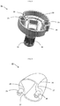
- Figure 2 shows a first capsule part (31), and figure 3 shows a second capsule part.
- the first capsule part (31) comprises an actuator mechanism (33) which is illustrated as a toothed wheel (34). Moreover, the shown first capsule part (31) comprises an indentation (36), capsule coupling means (35) and coupling means (39) for positioning of a figure (not shown).
- the second capsule part (32), shown in figure 3 comprises complementary capsule coupling means (35) whereby the two capsule parts can be interconnected via the capsule coupling means (35).
- the second capsule part moreover comprises two cut-outs, a cut-out (37) for passage of locking mechanism (21) (shown in figure 5 ) and a second cut-out (38) for abutment of the locking mechanism (21), respectively.
- the second cut-out has a concave configuration.
- the locking mechanism (21) is illustrated as a bayonet fastening in the form of a protrusion on the rotor that can pass the two cut-outs (36, 37) on the two capsule parts, and then the protrusion can be rotated in an anti-clockwise direction for fixed position with the protrusion by abutment on the side face of the second cut-out (38) on the second capsule part (32).
- the locking mechanism thereby retains both the two capsule parts and the rotor in interconnected position.
- Figure 4 shows the two capsule parts (31, 32) interconnected to a closed capsule.
- the one capsule part (31) comprises an actuator mechanism (33) in the form of a toothed wheel (34).
- the one capsule part also comprises an indentation (36) for passage of the locking mechanism (21) illustrated as a protrusion on the rotor in figure 5 .
- the second capsule part (32) comprises a cut-out (37) for passage of the locking mechanism (21) (shown in figure 5 ) and a second cut-out (38) for abutment of the locking mechanism (21).
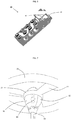
- Figure 5 shows the rotor with the circular periphery seen from above.
- the rotor comprises two locking mechanisms (21) in the shape of two protrusions and a centrally arranged through-going hole (22) and three swivel arms (23).
- the cut-outs (37, 38) in figure 3 are for passage of the locking mechanism (21), when the at least two capsule parts and the rotor are interconnected and securely locked to each other.
- the shown bayonet fastening is configured such that when the two capsule parts are interconnected and are conveyed partially through the centrally arranged through-going hole (22), the locking mechanism (21) in the shape of protrusions will, in turn, pass the cut-out (37) and then the capsule may be caused to rotate about the centre axis whereby the protrusion is turned and abuts on the concave cut-out (38), and thereby capsule and rotor are securely locked to each other about the axis of rotation in the same direction as the locking direction.
- the locking mechanism (21) is positioned at a distance along the centre axis from the central through-going hole (22) which is larger than the expanse of the first capsule part (31) when this first capsule part (31) only is connected to the rotor (20).
- the first capsule part (31) can rotate in the central through-going hole (22) without it being locked to the locking mechanism (21), and thereby the first capsule part can be rotated without rotating the rotor (20).
- Figure 6 shows the launch element (40) with the launch device (41) and a through-going slit (42).
- the launching position (41) is configured to completely or partially receive the actuator mechanism (33) whereby the actuator means (50), when it is introduced into the through-going slot, can engage with the actuator mechanism (33).
- the actuator mechanism (33) sits on the first capsule part (31), and the locking mechanism (21) is configured to lock the first capsule part (31) to the rotor only when the first capsule part (31) is connected to the second capsule part (22) to the effect that both capsule parts and the rotor (20) need to be interconnected via the locking mechanism (21) before a transfer of force from the capsule (30) comprising the actuator mechanism (33) to the rotor (20).
- the locking mechanism (21) is constituted by a bayonet fastening in the form of a protrusion. That protrusion is positioned at a distance from the centrally located through-going hole (22). The protrusion will be arranged over the first capsule part when it is mounted on its own in the central hole in the rotor and will thereby not lock the first capsule part to the rotor, and hence the first capsule part will be poor at transferring the rotation force to the rotor if it is attempted to insert only the rotor and the first capsule part in the launch element (40).
- the capsule may be completely or partially made of a transparent material. Thereby it is possible to see a figure placed within the capsule.
- Figure 7 shows an alternative construction of the two capsule parts (31, 32) and the rotor (20).
- the capsule is divided in the same plane as the axis of rotation and can be kept together by the locking mechanism (21) of the rotor which is, in this case, configured as a cylindrical band that squeezes around the two capsule parts that are formed of a centred circular through-going hole.
- the capsule is illustrated with an oval cross section, but may also have other cross-sections to achieve the same effect, eg circular.
- the two capsule parts (31, 32) are hinged onto the actuator mechanism (33) whereby the two capsule parts can be opened like the petals of a flower, which enables access to the capsule interior. Thereby a figure can be arranged within the capsule.
- the cylindrical band of the rotor can be pressed down over the capsule when the two capsule parts are closed and thereby ensure that the figure cannot be flung out by the rotor being launched from the launch pad.
- the actuator means (50) (shown in figure 1 ) is configured eg with an L-shaped cross-section whereby the actuator means can be introduced into the slit opening (42) in one direction only, meaning that the direction of rotation is, when the rotor is launched, such that, upon launching, the rotor locks the locking mechanism (21) whereby unintended separation of the capsule (30), including the two capsule parts, and the rotor (20) can be avoided.
- the rotor is likewise rotated in the clockwise direction when being launched in order to avoid that the locking mechanism is unlocked and that rotor and capsule parts are unintentionally separated.
Landscapes
- Life Sciences & Earth Sciences (AREA)
- Chemical & Material Sciences (AREA)
- Engineering & Computer Science (AREA)
- Food Science & Technology (AREA)
- Polymers & Plastics (AREA)
- Toys (AREA)
Claims (10)
- Jouet (10) comprenant un rotor (20) et une capsule agencée au centre (30), dans lequel la capsule comprend un mécanisme d'actionneur (33) qui est configuré pour coopérer avec un élément de lancement (40) et un moyen d'actionneur (50), dans lequel le moyen d'actionneur est configuré pour venir en prise avec le mécanisme d'actionneur (33) pour transférer une impulsion au rotor (20), selon lequel le rotor peut tourner et être lancé à partir de l'élément de lancement (40), caractérisé en ce que la capsule (30) est une partie distincte par rapport au rotor, et en ce que la capsule (30) comprend au moins deux parties de capsule (31, 32), selon lequel les deux parties de capsule peuvent être ouvertes lorsque le rotor et la capsule sont séparés, et dans lequel le rotor (20), la capsule (30) et le mécanisme d'actionneur (33) sont reliés les uns aux autres pour permettre que l'impulsion provenant du moyen d'actionneur (50) soit transférée au mécanisme d'actionneur (33) qui transmet l'impulsion de la capsule (30) au rotor (20), lorsque les au moins deux parties de capsule (31, 32) sont fermées.
- Jouet (10) selon la revendication 1, dans lequel le rotor (20) comprend un trou traversant circulaire centré (22) pour recevoir la capsule (30) lorsque les deux parties de capsule (31, 32) sont reliées entre elles.
- Jouet (10) selon l'une quelconque des revendications précédentes, dans lequel le rotor (20) comprend un mécanisme de verrouillage (21), selon lequel les au moins deux parties de capsule (31, 32) restent reliées l'une à l'autre et au rotor, lorsque le rotor (20) est lancé.
- Jouet (10) selon la revendication 3, dans lequel la première partie de capsule (31) comprend le mécanisme d'actionneur (33) et dans lequel le mécanisme de verrouillage (21) sur le rotor (20) est configuré de sorte que le mécanisme de verrouillage (21) verrouille la première partie de capsule (31) au rotor lorsque la première partie de capsule (31) est reliée à la deuxième partie de capsule (32), selon lequel les deux parties de capsule (31, 32) et le rotor (20) doivent être reliés entre eux via le mécanisme de verrouillage (21) avant qu'un transfert de force ne se produise à partir de la capsule (30) comprenant le mécanisme d'actionneur (33) au rotor (20).
- Jouet (10) selon la revendication 3 ou 4, dans lequel le mécanisme de verrouillage (21) est constitué d'une attache à baïonnette, dans lequel le rotor (20) comprend une ou plusieurs saillies qui sont configurées pour venir en prise avec un évidement (38) dans la capsule (30), selon lequel l'attache à baïonnette verrouille le rotor (20) à la capsule lorsque les deux parties de capsule sont reliées.
- Jouet (10) selon la revendication 2 et la revendication 5, dans lequel le mécanisme de verrouillage (21) est positionné à une certaine distance le long de l'axe central depuis le trou traversant central (22) qui est supérieure à l'étendue de la première partie de capsule (31) lorsque seule la première partie de capsule (31) est reliée au rotor (20) pour permettre à la première partie de capsule (31) de tourner sans le rotor (20).
- Jouet (10) selon l'une quelconque des revendications 3 à 6, dans lequel la direction de verrouillage du mécanisme de verrouillage (21) est identique à la direction de rotation du rotor (20), et dans lequel le mécanisme de verrouillage maintient les première et deuxième parties de capsule reliées entre elles pour permettre à une séparation accidentelle du rotor et de la capsule d'être empêchée lorsque le rotor est lancé.
- Jouet (10) selon l'une quelconque des revendications précédentes, dans lequel la capsule comprend, intérieurement, des moyens de couplage (39), selon lequel une figurine peut être agencée à l'intérieur de la capsule.
- Jouet (10) selon l'une quelconque des revendications précédentes, dans lequel au moins la partie de capsule est configurée à partir d'un matériau transparent.
- Jouet (10) selon l'une quelconque des revendications précédentes et la revendication 3, dans lequel le moyen d'actionneur (50) est configuré avec une section transversale correspondant à une section transversale d'une ouverture en fente (42) sur l'élément de lancement (40), selon lequel le moyen d'actionneur est apte à venir en prise avec et influencer le mécanisme d'actionneur dans une seule direction de rotation, selon lequel la direction de rotation du rotor, lorsqu'il est lancé, verrouillera le mécanisme de verrouillage (21), selon lequel une séparation accidentelle entre la capsule (30) et le rotor (20) est évitée.
Applications Claiming Priority (2)
| Application Number | Priority Date | Filing Date | Title |
|---|---|---|---|
| DKPA201570032 | 2015-01-21 | ||
| PCT/DK2016/050014 WO2016116109A1 (fr) | 2015-01-21 | 2016-01-18 | Jouet comprenant un rotor |
Publications (2)
| Publication Number | Publication Date |
|---|---|
| EP3247477A1 EP3247477A1 (fr) | 2017-11-29 |
| EP3247477B1 true EP3247477B1 (fr) | 2019-06-19 |
Family
ID=55398145
Family Applications (1)
| Application Number | Title | Priority Date | Filing Date |
|---|---|---|---|
| EP16705020.2A Active EP3247477B1 (fr) | 2015-01-21 | 2016-01-18 | Jouet comprenant un rotor |
Country Status (5)
| Country | Link |
|---|---|
| US (1) | US10137381B2 (fr) |
| EP (1) | EP3247477B1 (fr) |
| CN (1) | CN107427729B (fr) |
| DK (1) | DK3247477T3 (fr) |
| WO (1) | WO2016116109A1 (fr) |
Cited By (1)
| Publication number | Priority date | Publication date | Assignee | Title |
|---|---|---|---|---|
| WO2024240293A1 (fr) * | 2023-05-23 | 2024-11-28 | Schaeffler Technologies AG & Co. KG | Dispositif de cadre pour fixer et positionner des composants d'automatisation d'une station d'automatisation |
Families Citing this family (7)
| Publication number | Priority date | Publication date | Assignee | Title |
|---|---|---|---|---|
| JP1582942S (fr) * | 2017-02-28 | 2018-01-29 | ||
| USD844394S1 (en) | 2018-03-29 | 2019-04-02 | Kraft Foods Group Brands Llc | Mold |
| US10894342B2 (en) | 2018-03-29 | 2021-01-19 | Kraft Foods Group Brands Llc | System and method for molding comestible building blocks |
| US11253788B2 (en) | 2018-04-26 | 2022-02-22 | Lego A/S | Toy spinning top and toy system with a toy spinning top and a toy figurine |
| USD1115920S1 (en) | 2025-01-22 | 2026-03-03 | Aob Products Company | Target |
| USD1115921S1 (en) | 2025-01-22 | 2026-03-03 | Aob Products Company | Target |
| USD1125374S1 (en) | 2025-01-22 | 2026-05-05 | Aob Products Company | Target |
Family Cites Families (28)
| Publication number | Priority date | Publication date | Assignee | Title |
|---|---|---|---|---|
| US2051151A (en) * | 1935-07-16 | 1936-08-18 | Northill Co Inc | Aeronautical toy |
| US2561554A (en) * | 1948-07-14 | 1951-07-24 | Barist Michael | Device for spinning toys |
| US3473256A (en) * | 1967-03-23 | 1969-10-21 | Forrest E Tyler | Flying top |
| US3605328A (en) | 1969-12-10 | 1971-09-20 | Mattel Inc | Rotor launching toy |
| US3701216A (en) * | 1971-12-22 | 1972-10-31 | California R & D Center | Wheel apparatus and rack and pinion launcher enabling repeated strokes and having automatic ejector |
| US4030238A (en) * | 1976-05-04 | 1977-06-21 | Lakin Willis M | Rotating toys, particularly flying toys |
| US4107871A (en) * | 1977-01-12 | 1978-08-22 | Hornsby Jr James R | Propulsion toy |
| US4781642A (en) * | 1987-07-29 | 1988-11-01 | Victor Stanzel | Rotary flying toy |
| JPH05228265A (ja) * | 1992-02-21 | 1993-09-07 | Art Yoshii:Kk | 発光体付き回転飛行玩具 |
| JPH0691062A (ja) | 1992-09-16 | 1994-04-05 | Sankyo Seiki Mfg Co Ltd | ブロック玩具用ブロック・ユニット |
| US5525086A (en) * | 1995-03-13 | 1996-06-11 | Gentile; John | Launchable figurine device |
| JP3827253B2 (ja) | 1996-10-09 | 2006-09-27 | 株式会社システムワット | 組立ブロック及び組立式玩具システム |
| ES1041052Y (es) * | 1998-08-28 | 1999-11-01 | Nestle Sa | Helado perfeccionado. |
| US20020098768A1 (en) * | 2001-01-19 | 2002-07-25 | Kuo Yin Jyh | Audio and video effect flight toy |
| JP3944392B2 (ja) | 2001-12-27 | 2007-07-11 | 株式会社センテクリエイションズ | 回転玩具 |
| JP2004065593A (ja) | 2002-08-06 | 2004-03-04 | Takara Co Ltd | プロペラ飛行玩具装置 |
| US6921313B2 (en) * | 2003-02-14 | 2005-07-26 | Derrick Yu | Illuminated flying toy |
| CN2746957Y (zh) * | 2004-02-15 | 2005-12-21 | 史提夫·戴维斯 | 自稳定旋转玩具 |
| US7500898B2 (en) * | 2004-08-25 | 2009-03-10 | Jakks Pacific, Incorporation | Toy for rotating and launching an object |
| US20060099880A1 (en) * | 2004-08-25 | 2006-05-11 | Jakks Pacific, Inc. | Arm attachable toy for rotating and launching an object |
| WO2006088465A1 (fr) * | 2005-02-15 | 2006-08-24 | Chau King Sze | Jouet volant pour lancement a propulsion a helice |
| US7950976B2 (en) * | 2005-07-14 | 2011-05-31 | Jakks Pacific, Inc. | Toy for rotating and launching an object |
| US8128454B2 (en) * | 2005-07-14 | 2012-03-06 | Jakks Pacific, Inc. | Toy for rotating and launching an object |
| US20080096460A1 (en) * | 2006-10-06 | 2008-04-24 | Julio Sandoval | Small vehicle energized on handheld launcher |
| TW201034733A (en) | 2009-03-26 | 2010-10-01 | Genius Toy Taiwan Co Ltd | Injection building block unit |
| BR112014026003A2 (pt) | 2012-04-18 | 2017-06-27 | Lego As | conjunto de construção de brinquedo |
| CN102743882A (zh) * | 2012-07-30 | 2012-10-24 | 无锡同春新能源科技有限公司 | 一种将太阳能光伏发电作为供电源的发光竹蜻蜓 |
| US9610515B2 (en) * | 2013-02-25 | 2017-04-04 | Rehco, Llc | System to launch a toy entity and methods of play |
-
2016
- 2016-01-18 EP EP16705020.2A patent/EP3247477B1/fr active Active
- 2016-01-18 US US15/544,094 patent/US10137381B2/en active Active
- 2016-01-18 DK DK16705020.2T patent/DK3247477T3/da active
- 2016-01-18 WO PCT/DK2016/050014 patent/WO2016116109A1/fr not_active Ceased
- 2016-01-18 CN CN201680016679.0A patent/CN107427729B/zh active Active
Non-Patent Citations (1)
| Title |
|---|
| None * |
Cited By (1)
| Publication number | Priority date | Publication date | Assignee | Title |
|---|---|---|---|---|
| WO2024240293A1 (fr) * | 2023-05-23 | 2024-11-28 | Schaeffler Technologies AG & Co. KG | Dispositif de cadre pour fixer et positionner des composants d'automatisation d'une station d'automatisation |
Also Published As
| Publication number | Publication date |
|---|---|
| CN107427729A (zh) | 2017-12-01 |
| US20180008899A1 (en) | 2018-01-11 |
| EP3247477A1 (fr) | 2017-11-29 |
| US10137381B2 (en) | 2018-11-27 |
| DK3247477T3 (da) | 2019-09-23 |
| CN107427729B (zh) | 2020-05-19 |
| WO2016116109A1 (fr) | 2016-07-28 |
Similar Documents
| Publication | Publication Date | Title |
|---|---|---|
| US10137381B2 (en) | Toy comprising a rotor | |
| EP3247478B1 (fr) | Jouet comprenant un rotor, un mécanisme d'activation et un dispositif de lancement | |
| EP3012003B1 (fr) | Gyroscope jouet combiné pouvant être assemblé librement | |
| CN210057374U (zh) | 陀螺玩具 | |
| EP3424574A1 (fr) | Jouet toupie | |
| CN107466282B (zh) | 螺旋桨保护罩及使用该螺旋桨保护罩的无人机 | |
| EP3530334A1 (fr) | Jouet toupie | |
| US20160009381A1 (en) | System for fast fixing an accessory to a drone body | |
| US9314704B2 (en) | Toy vehicle track set | |
| CN105366048B (zh) | 多旋翼无人飞行设备 | |
| CN110294117A (zh) | 旋翼组件及具有旋翼组件的无人飞行器 | |
| EP3713724B1 (fr) | Unité de coupe de cheveux ayant une structure de couplage | |
| US20190248471A1 (en) | Locking mechanism, propeller, motor, propulsion system assembly, and aircraft | |
| CN205707370U (zh) | 便携式可折叠无人机 | |
| CN104986324A (zh) | 一种旋转锁止机构及具有其的植保无人机 | |
| ITTO20120624A1 (it) | Dispositivo paracadute | |
| CN106184770B (zh) | 一种无人机抛伞装置及无人机 | |
| US20160122013A1 (en) | Scissoring fold arrangement for dual plane four bladed rotor hubs | |
| CN211001845U (zh) | 抛投装置和无人机 | |
| ES2635498T3 (es) | Un sistema de liberación rápida para un conjunto de acoplamiento y cesta | |
| KR20190002758U (ko) | 무인기 | |
| US2427217A (en) | Rocket fin assembly | |
| EP3704984B1 (fr) | Casque de protection pour motocyclistes | |
| CN206569253U (zh) | 可隐藏式驱动装置及无人机 | |
| CN121588478A (zh) | 玩具陀螺以及带有玩具陀螺和玩具公仔的玩具系统 |
Legal Events
| Date | Code | Title | Description |
|---|---|---|---|
| STAA | Information on the status of an ep patent application or granted ep patent |
Free format text: STATUS: THE INTERNATIONAL PUBLICATION HAS BEEN MADE |
|
| PUAI | Public reference made under article 153(3) epc to a published international application that has entered the european phase |
Free format text: ORIGINAL CODE: 0009012 |
|
| STAA | Information on the status of an ep patent application or granted ep patent |
Free format text: STATUS: REQUEST FOR EXAMINATION WAS MADE |
|
| 17P | Request for examination filed |
Effective date: 20170815 |
|
| AK | Designated contracting states |
Kind code of ref document: A1 Designated state(s): AL AT BE BG CH CY CZ DE DK EE ES FI FR GB GR HR HU IE IS IT LI LT LU LV MC MK MT NL NO PL PT RO RS SE SI SK SM TR |
|
| AX | Request for extension of the european patent |
Extension state: BA ME |
|
| DAV | Request for validation of the european patent (deleted) | ||
| DAX | Request for extension of the european patent (deleted) | ||
| GRAP | Despatch of communication of intention to grant a patent |
Free format text: ORIGINAL CODE: EPIDOSNIGR1 |
|
| STAA | Information on the status of an ep patent application or granted ep patent |
Free format text: STATUS: GRANT OF PATENT IS INTENDED |
|
| INTG | Intention to grant announced |
Effective date: 20190118 |
|
| GRAS | Grant fee paid |
Free format text: ORIGINAL CODE: EPIDOSNIGR3 |
|
| GRAA | (expected) grant |
Free format text: ORIGINAL CODE: 0009210 |
|
| STAA | Information on the status of an ep patent application or granted ep patent |
Free format text: STATUS: THE PATENT HAS BEEN GRANTED |
|
| AK | Designated contracting states |
Kind code of ref document: B1 Designated state(s): AL AT BE BG CH CY CZ DE DK EE ES FI FR GB GR HR HU IE IS IT LI LT LU LV MC MK MT NL NO PL PT RO RS SE SI SK SM TR |
|
| REG | Reference to a national code |
Ref country code: GB Ref legal event code: FG4D |
|
| REG | Reference to a national code |
Ref country code: CH Ref legal event code: EP |
|
| REG | Reference to a national code |
Ref country code: IE Ref legal event code: FG4D |
|
| REG | Reference to a national code |
Ref country code: DE Ref legal event code: R096 Ref document number: 602016015516 Country of ref document: DE |
|
| REG | Reference to a national code |
Ref country code: AT Ref legal event code: REF Ref document number: 1144754 Country of ref document: AT Kind code of ref document: T Effective date: 20190715 |
|
| REG | Reference to a national code |
Ref country code: DK Ref legal event code: T3 Effective date: 20190919 |
|
| REG | Reference to a national code |
Ref country code: NL Ref legal event code: MP Effective date: 20190619 |
|
| PG25 | Lapsed in a contracting state [announced via postgrant information from national office to epo] |
Ref country code: NO Free format text: LAPSE BECAUSE OF FAILURE TO SUBMIT A TRANSLATION OF THE DESCRIPTION OR TO PAY THE FEE WITHIN THE PRESCRIBED TIME-LIMIT Effective date: 20190919 Ref country code: LT Free format text: LAPSE BECAUSE OF FAILURE TO SUBMIT A TRANSLATION OF THE DESCRIPTION OR TO PAY THE FEE WITHIN THE PRESCRIBED TIME-LIMIT Effective date: 20190619 Ref country code: HR Free format text: LAPSE BECAUSE OF FAILURE TO SUBMIT A TRANSLATION OF THE DESCRIPTION OR TO PAY THE FEE WITHIN THE PRESCRIBED TIME-LIMIT Effective date: 20190619 Ref country code: AL Free format text: LAPSE BECAUSE OF FAILURE TO SUBMIT A TRANSLATION OF THE DESCRIPTION OR TO PAY THE FEE WITHIN THE PRESCRIBED TIME-LIMIT Effective date: 20190619 Ref country code: SE Free format text: LAPSE BECAUSE OF FAILURE TO SUBMIT A TRANSLATION OF THE DESCRIPTION OR TO PAY THE FEE WITHIN THE PRESCRIBED TIME-LIMIT Effective date: 20190619 Ref country code: FI Free format text: LAPSE BECAUSE OF FAILURE TO SUBMIT A TRANSLATION OF THE DESCRIPTION OR TO PAY THE FEE WITHIN THE PRESCRIBED TIME-LIMIT Effective date: 20190619 |
|
| REG | Reference to a national code |
Ref country code: LT Ref legal event code: MG4D |
|
| PG25 | Lapsed in a contracting state [announced via postgrant information from national office to epo] |
Ref country code: GR Free format text: LAPSE BECAUSE OF FAILURE TO SUBMIT A TRANSLATION OF THE DESCRIPTION OR TO PAY THE FEE WITHIN THE PRESCRIBED TIME-LIMIT Effective date: 20190920 Ref country code: LV Free format text: LAPSE BECAUSE OF FAILURE TO SUBMIT A TRANSLATION OF THE DESCRIPTION OR TO PAY THE FEE WITHIN THE PRESCRIBED TIME-LIMIT Effective date: 20190619 Ref country code: RS Free format text: LAPSE BECAUSE OF FAILURE TO SUBMIT A TRANSLATION OF THE DESCRIPTION OR TO PAY THE FEE WITHIN THE PRESCRIBED TIME-LIMIT Effective date: 20190619 Ref country code: BG Free format text: LAPSE BECAUSE OF FAILURE TO SUBMIT A TRANSLATION OF THE DESCRIPTION OR TO PAY THE FEE WITHIN THE PRESCRIBED TIME-LIMIT Effective date: 20190919 |
|
| REG | Reference to a national code |
Ref country code: AT Ref legal event code: MK05 Ref document number: 1144754 Country of ref document: AT Kind code of ref document: T Effective date: 20190619 |
|
| PG25 | Lapsed in a contracting state [announced via postgrant information from national office to epo] |
Ref country code: RO Free format text: LAPSE BECAUSE OF FAILURE TO SUBMIT A TRANSLATION OF THE DESCRIPTION OR TO PAY THE FEE WITHIN THE PRESCRIBED TIME-LIMIT Effective date: 20190619 Ref country code: CZ Free format text: LAPSE BECAUSE OF FAILURE TO SUBMIT A TRANSLATION OF THE DESCRIPTION OR TO PAY THE FEE WITHIN THE PRESCRIBED TIME-LIMIT Effective date: 20190619 Ref country code: SK Free format text: LAPSE BECAUSE OF FAILURE TO SUBMIT A TRANSLATION OF THE DESCRIPTION OR TO PAY THE FEE WITHIN THE PRESCRIBED TIME-LIMIT Effective date: 20190619 Ref country code: AT Free format text: LAPSE BECAUSE OF FAILURE TO SUBMIT A TRANSLATION OF THE DESCRIPTION OR TO PAY THE FEE WITHIN THE PRESCRIBED TIME-LIMIT Effective date: 20190619 Ref country code: NL Free format text: LAPSE BECAUSE OF FAILURE TO SUBMIT A TRANSLATION OF THE DESCRIPTION OR TO PAY THE FEE WITHIN THE PRESCRIBED TIME-LIMIT Effective date: 20190619 Ref country code: EE Free format text: LAPSE BECAUSE OF FAILURE TO SUBMIT A TRANSLATION OF THE DESCRIPTION OR TO PAY THE FEE WITHIN THE PRESCRIBED TIME-LIMIT Effective date: 20190619 Ref country code: PT Free format text: LAPSE BECAUSE OF FAILURE TO SUBMIT A TRANSLATION OF THE DESCRIPTION OR TO PAY THE FEE WITHIN THE PRESCRIBED TIME-LIMIT Effective date: 20191021 |
|
| PG25 | Lapsed in a contracting state [announced via postgrant information from national office to epo] |
Ref country code: IT Free format text: LAPSE BECAUSE OF FAILURE TO SUBMIT A TRANSLATION OF THE DESCRIPTION OR TO PAY THE FEE WITHIN THE PRESCRIBED TIME-LIMIT Effective date: 20190619 Ref country code: SM Free format text: LAPSE BECAUSE OF FAILURE TO SUBMIT A TRANSLATION OF THE DESCRIPTION OR TO PAY THE FEE WITHIN THE PRESCRIBED TIME-LIMIT Effective date: 20190619 Ref country code: ES Free format text: LAPSE BECAUSE OF FAILURE TO SUBMIT A TRANSLATION OF THE DESCRIPTION OR TO PAY THE FEE WITHIN THE PRESCRIBED TIME-LIMIT Effective date: 20190619 Ref country code: IS Free format text: LAPSE BECAUSE OF FAILURE TO SUBMIT A TRANSLATION OF THE DESCRIPTION OR TO PAY THE FEE WITHIN THE PRESCRIBED TIME-LIMIT Effective date: 20191019 |
|
| PG25 | Lapsed in a contracting state [announced via postgrant information from national office to epo] |
Ref country code: TR Free format text: LAPSE BECAUSE OF FAILURE TO SUBMIT A TRANSLATION OF THE DESCRIPTION OR TO PAY THE FEE WITHIN THE PRESCRIBED TIME-LIMIT Effective date: 20190619 |
|
| PG25 | Lapsed in a contracting state [announced via postgrant information from national office to epo] |
Ref country code: PL Free format text: LAPSE BECAUSE OF FAILURE TO SUBMIT A TRANSLATION OF THE DESCRIPTION OR TO PAY THE FEE WITHIN THE PRESCRIBED TIME-LIMIT Effective date: 20190619 |
|
| PG25 | Lapsed in a contracting state [announced via postgrant information from national office to epo] |
Ref country code: IS Free format text: LAPSE BECAUSE OF FAILURE TO SUBMIT A TRANSLATION OF THE DESCRIPTION OR TO PAY THE FEE WITHIN THE PRESCRIBED TIME-LIMIT Effective date: 20200224 |
|
| REG | Reference to a national code |
Ref country code: DE Ref legal event code: R097 Ref document number: 602016015516 Country of ref document: DE |
|
| PLBE | No opposition filed within time limit |
Free format text: ORIGINAL CODE: 0009261 |
|
| STAA | Information on the status of an ep patent application or granted ep patent |
Free format text: STATUS: NO OPPOSITION FILED WITHIN TIME LIMIT |
|
| PG2D | Information on lapse in contracting state deleted |
Ref country code: IS |
|
| 26N | No opposition filed |
Effective date: 20200603 |
|
| PG25 | Lapsed in a contracting state [announced via postgrant information from national office to epo] |
Ref country code: MC Free format text: LAPSE BECAUSE OF FAILURE TO SUBMIT A TRANSLATION OF THE DESCRIPTION OR TO PAY THE FEE WITHIN THE PRESCRIBED TIME-LIMIT Effective date: 20190619 Ref country code: SI Free format text: LAPSE BECAUSE OF FAILURE TO SUBMIT A TRANSLATION OF THE DESCRIPTION OR TO PAY THE FEE WITHIN THE PRESCRIBED TIME-LIMIT Effective date: 20190619 |
|
| REG | Reference to a national code |
Ref country code: CH Ref legal event code: PL |
|
| REG | Reference to a national code |
Ref country code: BE Ref legal event code: MM Effective date: 20200131 |
|
| PG25 | Lapsed in a contracting state [announced via postgrant information from national office to epo] |
Ref country code: LU Free format text: LAPSE BECAUSE OF NON-PAYMENT OF DUE FEES Effective date: 20200118 Ref country code: FR Free format text: LAPSE BECAUSE OF NON-PAYMENT OF DUE FEES Effective date: 20200131 |
|
| PG25 | Lapsed in a contracting state [announced via postgrant information from national office to epo] |
Ref country code: CH Free format text: LAPSE BECAUSE OF NON-PAYMENT OF DUE FEES Effective date: 20200131 Ref country code: LI Free format text: LAPSE BECAUSE OF NON-PAYMENT OF DUE FEES Effective date: 20200131 Ref country code: BE Free format text: LAPSE BECAUSE OF NON-PAYMENT OF DUE FEES Effective date: 20200131 |
|
| PG25 | Lapsed in a contracting state [announced via postgrant information from national office to epo] |
Ref country code: IE Free format text: LAPSE BECAUSE OF NON-PAYMENT OF DUE FEES Effective date: 20200118 |
|
| PG25 | Lapsed in a contracting state [announced via postgrant information from national office to epo] |
Ref country code: MT Free format text: LAPSE BECAUSE OF FAILURE TO SUBMIT A TRANSLATION OF THE DESCRIPTION OR TO PAY THE FEE WITHIN THE PRESCRIBED TIME-LIMIT Effective date: 20190619 Ref country code: CY Free format text: LAPSE BECAUSE OF FAILURE TO SUBMIT A TRANSLATION OF THE DESCRIPTION OR TO PAY THE FEE WITHIN THE PRESCRIBED TIME-LIMIT Effective date: 20190619 |
|
| PG25 | Lapsed in a contracting state [announced via postgrant information from national office to epo] |
Ref country code: MK Free format text: LAPSE BECAUSE OF FAILURE TO SUBMIT A TRANSLATION OF THE DESCRIPTION OR TO PAY THE FEE WITHIN THE PRESCRIBED TIME-LIMIT Effective date: 20190619 |
|
| P01 | Opt-out of the competence of the unified patent court (upc) registered |
Effective date: 20230512 |
|
| PGFP | Annual fee paid to national office [announced via postgrant information from national office to epo] |
Ref country code: GB Payment date: 20260123 Year of fee payment: 11 |
|
| PGFP | Annual fee paid to national office [announced via postgrant information from national office to epo] |
Ref country code: DE Payment date: 20260121 Year of fee payment: 11 Ref country code: DK Payment date: 20260126 Year of fee payment: 11 |