EP3247546B1 - Aktuatorkühlvorrichtung und -verfahren - Google Patents
Aktuatorkühlvorrichtung und -verfahren Download PDFInfo
- Publication number
- EP3247546B1 EP3247546B1 EP16713646.4A EP16713646A EP3247546B1 EP 3247546 B1 EP3247546 B1 EP 3247546B1 EP 16713646 A EP16713646 A EP 16713646A EP 3247546 B1 EP3247546 B1 EP 3247546B1
- Authority
- EP
- European Patent Office
- Prior art keywords
- actuator
- distal
- spring
- proximal
- clamp plate
- Prior art date
- Legal status (The legal status is an assumption and is not a legal conclusion. Google has not performed a legal analysis and makes no representation as to the accuracy of the status listed.)
- Active
Links
Images










Classifications
-
- B—PERFORMING OPERATIONS; TRANSPORTING
- B29—WORKING OF PLASTICS; WORKING OF SUBSTANCES IN A PLASTIC STATE IN GENERAL
- B29C—SHAPING OR JOINING OF PLASTICS; SHAPING OF MATERIAL IN A PLASTIC STATE, NOT OTHERWISE PROVIDED FOR; AFTER-TREATMENT OF THE SHAPED PRODUCTS, e.g. REPAIRING
- B29C45/00—Injection moulding, i.e. forcing the required volume of moulding material through a nozzle into a closed mould; Apparatus therefor
- B29C45/17—Component parts, details or accessories; Auxiliary operations
- B29C45/72—Heating or cooling
- B29C45/73—Heating or cooling of the mould
- B29C45/7331—Heat transfer elements, e.g. heat pipes
-
- B—PERFORMING OPERATIONS; TRANSPORTING
- B29—WORKING OF PLASTICS; WORKING OF SUBSTANCES IN A PLASTIC STATE IN GENERAL
- B29C—SHAPING OR JOINING OF PLASTICS; SHAPING OF MATERIAL IN A PLASTIC STATE, NOT OTHERWISE PROVIDED FOR; AFTER-TREATMENT OF THE SHAPED PRODUCTS, e.g. REPAIRING
- B29C45/00—Injection moulding, i.e. forcing the required volume of moulding material through a nozzle into a closed mould; Apparatus therefor
- B29C45/17—Component parts, details or accessories; Auxiliary operations
- B29C45/26—Moulds
- B29C45/27—Sprue channels ; Runner channels or runner nozzles
- B29C45/28—Closure devices therefor
- B29C45/2806—Closure devices therefor consisting of needle valve systems
-
- B—PERFORMING OPERATIONS; TRANSPORTING
- B29—WORKING OF PLASTICS; WORKING OF SUBSTANCES IN A PLASTIC STATE IN GENERAL
- B29C—SHAPING OR JOINING OF PLASTICS; SHAPING OF MATERIAL IN A PLASTIC STATE, NOT OTHERWISE PROVIDED FOR; AFTER-TREATMENT OF THE SHAPED PRODUCTS, e.g. REPAIRING
- B29C45/00—Injection moulding, i.e. forcing the required volume of moulding material through a nozzle into a closed mould; Apparatus therefor
- B29C45/17—Component parts, details or accessories; Auxiliary operations
- B29C45/26—Moulds
- B29C45/27—Sprue channels ; Runner channels or runner nozzles
- B29C45/28—Closure devices therefor
- B29C45/2806—Closure devices therefor consisting of needle valve systems
- B29C45/281—Drive means therefor
-
- B—PERFORMING OPERATIONS; TRANSPORTING
- B29—WORKING OF PLASTICS; WORKING OF SUBSTANCES IN A PLASTIC STATE IN GENERAL
- B29C—SHAPING OR JOINING OF PLASTICS; SHAPING OF MATERIAL IN A PLASTIC STATE, NOT OTHERWISE PROVIDED FOR; AFTER-TREATMENT OF THE SHAPED PRODUCTS, e.g. REPAIRING
- B29C45/00—Injection moulding, i.e. forcing the required volume of moulding material through a nozzle into a closed mould; Apparatus therefor
- B29C45/17—Component parts, details or accessories; Auxiliary operations
- B29C45/72—Heating or cooling
-
- B—PERFORMING OPERATIONS; TRANSPORTING
- B29—WORKING OF PLASTICS; WORKING OF SUBSTANCES IN A PLASTIC STATE IN GENERAL
- B29C—SHAPING OR JOINING OF PLASTICS; SHAPING OF MATERIAL IN A PLASTIC STATE, NOT OTHERWISE PROVIDED FOR; AFTER-TREATMENT OF THE SHAPED PRODUCTS, e.g. REPAIRING
- B29C45/00—Injection moulding, i.e. forcing the required volume of moulding material through a nozzle into a closed mould; Apparatus therefor
- B29C45/17—Component parts, details or accessories; Auxiliary operations
- B29C45/72—Heating or cooling
- B29C45/73—Heating or cooling of the mould
-
- B—PERFORMING OPERATIONS; TRANSPORTING
- B29—WORKING OF PLASTICS; WORKING OF SUBSTANCES IN A PLASTIC STATE IN GENERAL
- B29C—SHAPING OR JOINING OF PLASTICS; SHAPING OF MATERIAL IN A PLASTIC STATE, NOT OTHERWISE PROVIDED FOR; AFTER-TREATMENT OF THE SHAPED PRODUCTS, e.g. REPAIRING
- B29C45/00—Injection moulding, i.e. forcing the required volume of moulding material through a nozzle into a closed mould; Apparatus therefor
- B29C45/17—Component parts, details or accessories; Auxiliary operations
- B29C45/26—Moulds
- B29C45/27—Sprue channels ; Runner channels or runner nozzles
- B29C45/28—Closure devices therefor
- B29C45/2806—Closure devices therefor consisting of needle valve systems
- B29C2045/2868—Closure devices therefor consisting of needle valve systems with an incorporated heat pipe
-
- B—PERFORMING OPERATIONS; TRANSPORTING
- B29—WORKING OF PLASTICS; WORKING OF SUBSTANCES IN A PLASTIC STATE IN GENERAL
- B29C—SHAPING OR JOINING OF PLASTICS; SHAPING OF MATERIAL IN A PLASTIC STATE, NOT OTHERWISE PROVIDED FOR; AFTER-TREATMENT OF THE SHAPED PRODUCTS, e.g. REPAIRING
- B29C45/00—Injection moulding, i.e. forcing the required volume of moulding material through a nozzle into a closed mould; Apparatus therefor
- B29C45/17—Component parts, details or accessories; Auxiliary operations
- B29C45/72—Heating or cooling
- B29C2045/7271—Cooling of drive motors
-
- B—PERFORMING OPERATIONS; TRANSPORTING
- B29—WORKING OF PLASTICS; WORKING OF SUBSTANCES IN A PLASTIC STATE IN GENERAL
- B29C—SHAPING OR JOINING OF PLASTICS; SHAPING OF MATERIAL IN A PLASTIC STATE, NOT OTHERWISE PROVIDED FOR; AFTER-TREATMENT OF THE SHAPED PRODUCTS, e.g. REPAIRING
- B29C45/00—Injection moulding, i.e. forcing the required volume of moulding material through a nozzle into a closed mould; Apparatus therefor
- B29C45/17—Component parts, details or accessories; Auxiliary operations
- B29C45/72—Heating or cooling
- B29C45/73—Heating or cooling of the mould
- B29C2045/735—Heating or cooling of the mould heating a mould part and cooling another mould part during moulding
-
- B—PERFORMING OPERATIONS; TRANSPORTING
- B29—WORKING OF PLASTICS; WORKING OF SUBSTANCES IN A PLASTIC STATE IN GENERAL
- B29K—INDEXING SCHEME ASSOCIATED WITH SUBCLASSES B29B, B29C OR B29D, RELATING TO MOULDING MATERIALS OR TO MATERIALS FOR MOULDS, REINFORCEMENTS, FILLERS OR PREFORMED PARTS, e.g. INSERTS
- B29K2995/00—Properties of moulding materials, reinforcements, fillers, preformed parts or moulds
- B29K2995/0012—Properties of moulding materials, reinforcements, fillers, preformed parts or moulds having particular thermal properties
- B29K2995/0013—Conductive
Definitions
- Solid sheet metal springs for cooling actuators have been used in injection molding systems such as disclosed in U.S. publication no. 20140353875 where the springs are spaced from the actuator housing body, U.S. Patent Nos. 8,349,244 and 8,562,336 .
- These prior cooling devices comprise a solid body of sheet metal of relatively high mass that is adapted to exert a spring force by forced deformation of a portion of the solid sheet of metal.
- This same sheet of metal is purposely disposed in direct heat conductive contact with a relatively large surface of the hot metal housing of an actuator that itself is disposed in heat conductive communication with a fluid distribution manifold that is heated to an elevated temperature sufficient to melt polymer materials.
- the ability of the sheet metal spring body to readily deform and provide an effective spring force is degraded by the very high level of heat to which the sheet metal body is subjected, the sheet metal spring body also acting to conduct heat from the actuator housing body to a cool clamp plate.
- the spring or spring loadable interconnection 506 has an amount or degree of mass that renders the spring 506 substantially non-heat conductive between the proximal and distal members.
- the area of engagement or contact between engagement surfaces 506es and one or both of surfaces 504us or 502us preferably minimizes, enables or imparts a minimal amount of, heat conduction between members 504 and 502 via or through spring or spring loadable interconnection 506.
- the area of engagement or contact between engagement surfaces 506es and one or both of surfaces 504us or 502us is preferably less than about 10 square mm, typically less than about 7.5 mm and more typically less than about 5 mm.
- the actuator 10 typically comprises a housing body 12 that is mounted in thermally conductive contact along the axis A to one or more actuator mounts 50, 60, 803 that are mounted downstream in heat conductive communication with or contact with or on the manifold along the axis A, the housing body 12 having a surface 121s that is spaced laterally 12ld from the axis A, the proximal base or member 504 being mounted in heat conductive contact with and to the lateral surface 121s such that the proximal base or member 504 is spaced laterally apart from contact with the one or more actuator mounts 50, 60, 803.
- the apparatus can further comprise one or more heat conductive tubes 517a, 517b, 517c, 517d containing a heat conductive liquid embedded within one or the other or both of the proximal 504 and distal 502 members.
- the distal 502 and proximal 504 members can be heat transmissively interconnected or engaged with each other by heat transmissive rods 507 or tubes 517r that are intimately engaged with the members 502, 504.
- the apparatus can further comprise one or more hollow heat conductive tubes 517ah having a cavity containing heat conductive fluid, the one or more tubes 517ah being embedded within the body of the housing of the actuator 10, 12.
- the distal member 502 has a proximal exterior surface 502b that is adapted to be engaged and slidable against a complementary surface 12ls, 12as of the housing body 12, 12a of the actuator 10 such that heat thermally conducts between the housing body 12, 12a and the distal arm or member 502, the distal end surface 502a of the distal arm or member being movable toward and away from the actuator 10 by sliding movement of the proximal exterior surface 502b of the distal arm or member 502 on the complementary surface 121s, 12as of the actuator.
- the spring loaded interconnection 506 can be adapted to urge the distal end surface 502a of the distal arm or member into a compression of at least 0.07 kg per square centimeter (1 pound per square inch (psi)) with the clamp plate.
- the lateral surface 121s and the proximal base member 504aa are preferably laterally spaced apart 12ld from direct heat conductive communication with the heated manifold 20.
- the clamp plate is typically cooled.
- the clamp plate, the mold, the manifold, the actuator and the cooling device are typically assembled together in an arrangement wherein the spring 506a is resiliently compressed up to a maximum of about 3 mm urging the distal end surface 502a of the distal arm or member into compressed engagement with the clamp plate 80a.
- the apparatus can include two or more separate cooling devices each comprised of a distal arm or member 502 mounted via spring loadable interconnection to a proximal base or member 504, each separate cooling device being separately mounted to the housing body 12, 12a of the actuator and separately assemblable together with the clamp plate, the mold, the actuator and the manifold such that the distal end surface of the distal arm or member of each separate cooling device is in compressed engagement with the clamp plate under the spring loadable interconnection 506 between each separate distal end arm 502 and proximal base or member 504.
- the apparatus can further comprise a mount 803 separating the actuator housing from direct contact with the manifold, the mount being cooled and having an upstream mounting surface in thermally conductive communication with a complementary mounting surface 12d of the actuator 10 and a downstream mounting surface in thermally conductive communication with the manifold 20.
- a mount 803 is preferably comprised of a thermally conductive metal that is cooled to a temperature of less than about 65 degrees centigrade (150 degrees F).
- the actuator 10 can be interconnected to a valve pin 17 that is mounted to the manifold and extends through a fluid material feed bore 22 in the manifold 20.
- the proximal base or member 504 is typically rigidly attached in thermally conductive contact to the laterally spaced surface 121s the housing body 12, 12a.
- the distal arm or member 502, 502b is typically attached to the actuator such that the arm 502, 502b is disposed in slidable thermally conductive contact with the lateral surface 121s, 12as of the housing body.
- the distal arm or member can comprise a rod 502r slidably disposed within a complementary bore 12bo disposed within the housing body 12, 12a of the actuator 10, the complementary bore 12bo and the rod 502r being configured such that an exterior surface 502b of the rod 502r is slidably engaged in thermally conductive contact against an interior surface 12si, 12asi of the complementary bore 12bo.
- the mass of the spring loadable interconnection minimizes, enables or imparts a minimal amount of, heat conduction between the proximal and distal arms or members via or through the spring or spring loadable interconnection 506.
- the mass of the spring loadable interconnection 506 is typically less than about 10 grams, more typically less than about 7.5 grams and most typically less than about 5 grams.
- the spring or spring loadable interconnection 506 can have engagement surfaces 506es that engage against complementary opposing engagement surfaces (504us, 502us) of proximal 504 and distal 502 members having a selected area of engagement that renders spring 506 substantially non-heat conductive between the proximal and distal arms or members.
- the area of engagement or contact between engagement surfaces 506es and one or both of surfaces 504us or 502us minimizes, enables or imparts a minimal amount of, heat conduction between members 504 and 502 via or through spring or spring loadable interconnection 506.
- the area of engagement or contact between engagement surfaces 506es and one or both of surfaces 504us or 502us is typically less than about 10 square mm, more typically less than about 7.5 square mm and most typically less than about 5 square mm.
- the actuator 10 preferably comprises a housing body 12 that is mounted in thermally conductive contact along the axis A to one or more actuator mounts 50, 60, 803 that are mounted downstream in heat conductive communication with or contact with or on the manifold along the axis A, the housing body 12 having a surface 121s that is spaced laterally 12ld from the axis A, the proximal base or member 504 being mounted in heat conductive contact with and to the lateral surface 121s such that the proximal base or member 504 is spaced laterally apart from contact with the one or more actuator mounts 50, 60, 803.
- Such an apparatus can further comprise one or more heat conductive tubes 517a, 517b, 517c, 517d containing a heat conductive liquid embedded within one or the other or both of the proximal 504 and distal 502 members.
- the distal 502 and proximal 504 members can be heat transmissively interconnected or engaged with each other by heat transmissive rods 507 or tubes 517r that are intimately engaged with the members 502, 504.
- the apparatus can further comprise one or more hollow heat conductive tubes 517ah having a cavity containing heat conductive fluid, the one or more tubes 517ah being embedded within the body of the housing of the actuator 10, 12.
- the distal member 502 has a proximal exterior surface 502b that is adapted to be engaged and slidable against a complementary surface 12ls, 12as of the housing body 12, 12a of the actuator 10 such that heat thermally conducts between the housing body 12, 12a and the distal arm or member 502, the distal end surface 502a of the distal arm or member being movable toward and away from the actuator 10 by sliding movement of the proximal exterior surface 502b of the distal arm or member 502 on the complementary surface 121s, 12as of the actuator.
- the spring loaded interconnection 506 is preferably adapted to urge the distal end surface 502a of the distal arm or member into a compression of at least 0.07 kg per square centimeter (1 pound per square inch (psi)) with the clamp plate.
- the lateral surface 12ls and the proximal base or member 504 are typically laterally spaced apart 12ld from direct heat conductive communication with the heated manifold 20.
- the clamp plate can be cooled.
- the clamp plate, the mold, the manifold, the actuator and the cooling device are typically assembled together in an arrangement wherein such that the spring 506a is resiliently compressed up to a maximum of about 3 mm urging the distal end surface 502a of the distal arm or member into compressed engagement with the clamp plate 80a.
- the apparatus can include two or more separate cooling devices each comprised of a distal arm or member 502 mounted via spring loadable interconnection to a proximal base or member 504, each separate cooling device being separately mounted to the housing body 12, 12a of the actuator and separately assemblable together with the clamp plate, the mold, the actuator and the manifold such that the distal end surface of the distal arm or member of each separate cooling device is in compressed engagement with the clamp plate under the spring loadable interconnection 506 between each separate distal end arm 502 and proximal base or member 504.
- the apparatus can further comprise a mount 803 separating the actuator housing 19 from direct contact with the manifold, the mount being cooled and having an upstream mounting surface in thermally conductive communication with a complementary mounting surface 12d of the actuator 10 and a downstream mounting surface in thermally conductive communication with the manifold 20.
- a mount 803 is typically comprised of a thermally conductive metal that is cooled to a temperature of less than about 65 degrees centigrade (150 degrees F).
- the actuator 10 is preferably interconnected to a valve pin 17 that is mounted to the manifold and extends through a fluid material feed bore 22 in the manifold 20.
- the proximal base or member 504 can be rigidly attached in thermally conductive contact to the laterally spaced surface 121s the housing body 12, 12a.
- the distal arm or member 502, 502b can be attached to the actuator such that the arm 502, 502b is disposed in slidable thermally conductive contact with the lateral surface 121s, 12as of the housing body.
- the distal arm or member can comprises a rod 502r slidably disposed within a complementary bore 12bo disposed within the housing body 12, 12a of the actuator 10, the complementary bore 12bo and the rod 502r being configured such that an exterior surface 502b of the rod 502r is slidably engaged in thermally conductive contact against an interior surface 12si, 12asi of the complementary bore 12bo.
- the apparatus 5 includes a cooling device 800 that is formed having a proximal mount 803 that is mounted between the downstream end of the actuator housing 12 and the heated manifold 20.
- a pair of upstream extending legs 800l extend upstream from the mount 803.
- the cooling device 800 is formed and adapted to form a reception aperture or recess 800ra that is complementary to and receives the actuator housing 12 such that the legs 800l are disposed in close proximity to the lateral outer surfaces 12los of the actuator housing 12.
- the legs 800l are formed to have an upstream extending longitudinal length UL that disposes the distal-most edge surface 800a of the legs 800l upstream beyond the upstream-most extending surface 12u of the actuator 12 when the actuator 12 is mounted in operating format within the reception aperture 800ra.
- the legs 800l are configured to have one or spring joints 800s along the longitudinal length UL of the legs 800l. Spring joints 800s are resiliently deformable such that when the legs 800l are subject to a compressive force along the longitudinal length UL of the legs 800l, the spring joints exert a spring force UF.
- the longitudinal length UL of the legs 800l, the clamp plate 80, manifold 20, actuator housing 12 and their mounting and interconnection components are selected, arranged and formed such that when the clamp plate 80, manifold 20, actuator 12 and cooling device 800 are assembled into operating format, the undersurface 80a of the clamp plate intimately engages with the distal end surface 800a under compression to cause the spring joints 800s to exert the UF force by surface 800a against surface 80a.
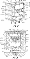
- the same components are formed and arranged together with the formation and arrangement of cooling device 500 such that the distal end most surface 502a of distal member 502 engages the undersurface 80a of plate 80 under compression from spring load force UF, Fig. 3 , exerted by springs 506 of cooling device 500 when all such components are assembled into operating format.
- spring or spring loadable interconnection 506 means a device that is disposed and engaged between or with the distal 502 and proximal 504 members and imparts a spring force UF therebetween at least when the apparatus is assembled and the manifold 20 is brought up to elevated operating temperature. As shown in all embodiments described herein where independent springs 506 such as shown in Figs.
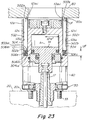
- such springs typically comprise one or more conventional coil, leaf, flat wire wave, Belleville or conical spring(s) having an upper end 506u and a lower end 506l that respectively engage via engagement surfaces 506es against and between a complementary engagement surfaces 502us, 504us of the distal member 502, 507, 507m and the proximal member 504, 504aa such that the spring 506 is compressed and the distal member 502 is forcibly urged under the force UF of the spring when compressed in an upstream direction to compress the distal end surface 502a or 507a under such force UF into engagement with the undersurface 80a of the clamping plate 80 at least when the apparatus is assembled and the manifold brought up to an elevated operating temperature.
- Such coil or leaf or flat wire wave or Belleville or conical spring(s) typically have a degree of resilient compression that is six or more times the degree of resilient compression of the plate springs of U.S. Patent Nos. 8,349,244 and 8,562,336 , typically having a degree of resilient or elastic compression of at least about 3 mm meaning that said coil et al. springs can be repeatedly compressed by at least about 3 mm and resiliently or elastically expand or revert back to their original uncompressed condition, length or state.
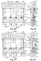
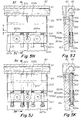
- the proximal 504 and distal 502 arms or members typically comprise mechanically independent heat conductive bodies or members 502, 504 that are interconnected via a pin or rod or slot and engaged with each other via a spring or spring loadable interconnection 506 that is typically comprised of a non-heat conductive spring, such as a coil spring as shown in Figs. 3 , 5-5K , 23 , 25-25E or one or more stacked leaf, belleville, conical or disc washers 506w or springs such as shown in Fig. 5L that act as a spring 506 between the distal and proximal members.
- a non-heat conductive spring such as a coil spring as shown in Figs. 3 , 5-5K , 23 , 25-25E or one or more stacked leaf, belleville, conical or disc washers 506w or springs such as shown in Fig. 5L that act as a spring 506 between the distal and proximal members.
- the spring or spring loadable interconnection 506 exerts a spring force UF, Figs. 3 , 5C , 5L , 23 , 25D , between the proximal base or member 504 and the distal arm or member 502 at least when the apparatus 5 is assembled and the manifold is brought to an elevated operating temperature.
- the spring or spring loadable interconnection 506 typically has engagement surfaces 506es that engage against complementary opposing engagement surfaces 504us and 502us of proximal 504 and distal 502 members such that heat conduction between members 504 and 502 is minimized and such that the spring 506 is substantially non-heat conductive.
- the spring or spring loadable interconnection 506 is preferably selected to have an amount or degree of mass (typically less than about 10 grams and more typically less than about 5 grams) that renders the spring 506 substantially non-heat conductive and minimizes, enables or imparts a minimal amount of, heat conduction between members 504 and 502 via or through spring or spring loadable interconnection 506.
- the mass of spring loadable interconnection 506 is preferably less than about 10 and most preferably less than about 5 grams.
- the area of engagement or contact between engagement surfaces 506es and one or both of surfaces 504us or 502us is preferably selected to be an amount or degree (typically less than about 10 square mm, typically less than about 7.5 square mm and more typically less than about 5 square mm) that renders the spring 506 substantially non-heat conductive and minimizes, enables or imparts a minimal amount of, heat conduction between members 504 and 502 via or through spring or spring loadable interconnection 506.
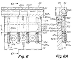
- Individual springs can be disposed around or in connection with each individual rod 507 or tube that may be employed for interconnecting a proximal base 504 and a distal member 502 as shown for example in Figs. 5B , 5D , 5F , 6 et al. However, a separate spring is not necessarily required for use in connection with each individual rod 507 as shown for example in Figs.
- the springs 506 that are associated with the other of the rods 507 in such embodiments being sufficient to supply the necessary force UF to maintain the distal end surface 502s in heat conductive contact with the undersurface 80a of the cool top clamp plate 80 when the system is assembled and the manifold brought up to elevated operating temperature.
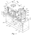
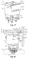
- Figs. 1-25G show an injection molding apparatus 5 comprised of an actuator 10 having a housing body 12, 12a that is thermally conductive and mounted in thermal communication with a heated manifold 20 into which fluid injection material 102 is injected from an injection machine 100 into and through one or more manifold distribution channels 22 that deliver fluid downstream to a downstream fluid delivery channel 200 such as the bore of a nozzle that terminates at its downstream end in a gate 304 that communicates with the cavity 302 of a mold 300.
- the actuator 10 includes a piston 14 that is controllably drivable along a drive axis A in a reciprocal upstream and downstream direction together with a valve pin 17 that is interconnected to the piston 14.
- the valve pin 17 is mounted within a complementary receiving aperture 91a of a bushing 91, the outside surface of the pin 17 mating with an interior surface of the aperture 91a and being slidable in an upstream and downstream direction axial A direction within the aperture 91a of the bushing 91 such that injection fluid that flows through channels 22, 200 is substantially prevented from flowing upstream through mounting aperture 91a.
- the bushing 91 is fixedly mounted within the body of the heated manifold 20 via bushing screw 92 that is screwably engaged within a complementary threaded receiving aperture bored within the heated manifold 20.
- the bushing 91, screw 92, actuator 10 and valve pin 17 are all adapted and arranged such that the valve pin 17 is controllably drivable upstream and downstream through both the manifold distribution channel 22 and the downstream nozzle channel 200 between a downstream-most gate closed position and one or more upstream gate open positions.
- the actuator housing 12 is typically mounted axially A upstream of and on or to the heated manifold 20.
- the actuator 10 can be mounted on or to the manifold via either or both mounts or spacers 60 and a water cooled cooling device or mount 803 as disclosed in U.S. patent no. 8,349,244 .
- the downstream axially facing surface 12d of the actuator housing 12 is also typically mounted on or to the stabilization mount 50.
- the cooling mount 803 and spacers 60 are mounted on or to an upstream surface of the stabilization mount 50.
- the downstream axially facing surface 12d of the actuator housing 12 is mounted in direct heat or thermally conductive contact with one or more of the mounts 60, 50, 803 that are in turn mounted in direct heat conductive contact or direct heat conductive communication with the heated manifold in axial alignment with axis A of the actuator housing and valve pin 17.
- mounts 50, 60, 803 act as insulators that prevent or retard the communication or conduction of heat from the heated manifold 20 through the mounts 50, 60, 803 to the lateral surface 12ls of the actuator body 12 that is spaced laterally 12ld from the drive axis A of the actuator 10 and valve pin 17 a distance 12ld sufficient to prevent or substantially retard conduction of heat through ambient air or through the housing body 12, valve pin 17 or mounts 50, 60, 803.
- heat is conducted or communicated from the heated manifold 20 to the housing body 12 such heat is conducted from the housing body 12 to the proximal member 504, 504aa further to the distal member 502, 502u and finally to the cool clamp plate 80 as described herein.
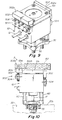
- the cooling device 500 comprises a heat transmitter that is comprised of a distal arm or member or assembly 502, 502r, 509, 509a, 509b, 507, 506, 506bi and a proximal base or member 504, the distal arm or member 502 or assembly being mounted by a spring loadable interconnection or engagement 506 to or with a proximal base or member 504, 504a, 504aa.
- the proximal base or member 504, 504a, 504aa is preferably mounted such that a complementary surface of the member 504, 504a, 504aa is disposed or mounted in intimate or compressed thermally conductive contact on, to or against a surface 121s, 12si of the housing body 12 that is spaced laterally 12ld away from the axis A of the actuator 10 and valve pin 17.
- the location of the mounting of the proximal member 504, 504a, 504aa is arranged such that the proximal base or member 504 is spaced laterally apart from contact with the axially mounted actuator mounts 50, 60, 803 that are directly mounted in close adjacency to and in thermal communication with the heated manifold 20 and on which the proximal end 12d of the actuator housing 12 is directly axially A mounted.
- the distal arm or member 502 is preferably comprised of a highly thermally conductive material and has a distal end surface 502a that is adapted to compressibly engage against an undersurface 80a of the clamp plate 80 under a spring load from the spring loadable interconnection 506 between the distally extending arm 502 and the proximal base or member 504 when all components of the system 5 are fully assembled and the heated manifold is brought up to an elevated operating temperature.
- the system 5 can be adapted and arranged such that the distal end surface 502a is not engaged under a compressive force when the system is in a cold non operating condition when the system 5 is initially assembled before the manifold 20 is heated to operating temperature or when the system 5 is shut down and allowed to return to room temperature after the manifold 20 has been heated up to operating temperature.
- the system 5 is preferably adapted and arranged such that compressive force between distal end surface 502a and the surface 80a of the clamp plate 80 occurs only when the system 5 including manifold 20 is brought up to normal elevated operating temperature.
- the distal arm 502 or rod 502r comprises a heat conductive independent body that is independent of and mounted on an independent compressible spring body 506, the degree of upstream and downstream movement Q along or substantially parallel to the axis A, ranges from 0 mm when the system 5 is in a cold or room temperature condition up to a maximum of about 3 mm when the system 5 is brought up to normal elevated operating temperature (such as between about 150 and 450 degrees F).
- normal elevated operating temperature such as between about 150 and 450 degrees F.
- the arm 502 is arranged and adapted for lateral L movement relative to the axial direction A of the actuator 10, the degree of lateral movement Q', Fig. 14 , ranges from 0 mm when the system 5 is in a cold or room temperature condition up to a maximum of about 3 mm when the system 5 is brought up to normal elevated operating temperature.
- the independent spring body 506 in the Figs. 1-14 , 21-24 embodiments is resilient such that after being compressed Q by up to about 3 mm when the system is at operating temperature, the independent spring body 506 will return back to its original uncompressed or non-compressed axial spring length or state when the system returns to room temperature.
- the degree of upstream and downstream movement Q" of the distal arm 502 along or substantially parallel to the axis A ranges from 0 mm when the system 5 is in a cold or room temperature condition up to a maximum of about 0.5 mm when the system 5 is brought up to normal elevated operating temperature (such as between about 150 and 450 degrees F).
- the arm 502 has an exterior or proximally disposed surface 502b for making contact with and receiving heat from the actuator housing body components 12, 12a via engagement between an exterior arm surface 502b and a laterally disposed complementary mating surface 12ls, 12as of the housing body 12.
- the arm 502 transmits heat received via the proximal surface 502b to the distal end surface 502a and in turn to the relatively cool clamp plate 80 via compressed engagement between surface 502a and a complementary undersurface 80s of the clamp plate 80.
- the arm 502, 509a also receives heat from the actuator housing 12 by transmission of heat through rods or tubes 507 which in turn receive heat from the base member 504 which itself receives heat from the actuator housing 12 by intimate compressed engagement with an exterior laterally disposed surface 121 of the housing 12.
- the laterally disposed actuator surface 121 of the housing 12 is spaced a lateral distance 12ld away from the drive axis A of the valve pin 17 because the valve pin 17 comes into direct thermal contact with the heated injection fluid 102.
- the heat transmission device 500 is disposed in a laterally spaced position away from the valve pin 17 and the valve pin axis A such that the base 504 is removed from direct thermal contact or thermal communication with the axis or the valve pin 17.
- the proximal base member 504 is rigidly attached to the lateral actuator surface 121 such as via a bolt or screw 504s such that a complementary surface 504b of the base member 504 is engaged in intimate heat conductive contact with the lateral disposed surface 121 that is spaced laterally 12 ld from the axis.
- the base 504 of the rods 502r are engaged with a laterally disposed actuator surface 12si that is spaced a lateral distance 12ld away from the drive axis A of the valve pin 17.
- the heat transmission rods 502r are disposed in a laterally spaced position away from the mounts 50, 60, 803, valve pin 17 and axis A such that the base 504 of the rods 502r is removed from direct or closely adjacent thermal contact or communication with the axis A or the valve pin 17.
- the actuator 10 comprises a housing body 12, 12a that is thermally conductive and mounted in thermal communication with the manifold 20 as described above.
- the proximal base or member 504 of the cooling device 500 is mounted to the housing body 12 of the actuator 10 in an arrangement where the distal end surface 502a of the distal arm or member 502 makes compressed contact with the clamp plate surface 80a such that the end surface 502a moves or travels some distance relative to the actuator housing 12, 12a to which the arm 502 is mounted.
- the arm 502 and distal engagement surface 502a is movable via the compressible spring 506a toward and away from the actuator 10.
- the distally extending arm or rod or tube 502r is movable toward and away from the actuator housing 12 via a compressible spring 506a.
- the thermally conductive rods 502r are mounted to proximal guides 504 which are in turn mounted to the actuator housing body 12. As shown, the rods 502r are slidably disposed within complementary receiving apertures or bores 12bo bored into the housing body 12.
- the rods 502r have an exterior surface 502b that are slidably engaged with an interior surface 12si, 12asi of the housing bodies 12, 12a which cause heat to be thermally transmitted from the housing bodies 12, 12a to the rods 502r which in turn transmit heat to the clamp plate 80 via compressed contact between surface 502a and surface 80a. Up and down movement of the rods 502r within the apertures 12bo occurs with the surfaces 502b and 12si and 12asi sliding against each other in engaged contact.
- the cooling devices 500 are mounted and arranged such that the proximally disposed arm surfaces 502b are maintained in slidable engaged contact with the complementary housing body surfaces 121s, 12as, the surfaces 502b receiving heat from the housing bodies 12, 12a and in turn transmitting such received heat to the clamp plate 80 via compressed contact between surfaces 502a and 80a.
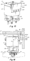
- the distal arm or member 502 and proximal base or member 504 are formed as a single unitary body 503 of highly conductive metal.
- the spring load in such unitary bodies 503 is created via deformation of the unitary bodies 503 such that when the clamp plate 80, mold 300, manifold 20, actuator 10 and cooling device 503 are all assembled together, the unitary body 503 resiliently deforms under compression to travel to a different position 502d relative to the actuator housing 12 to which the body 503 is mounted and relative to the original position 502o that the unitary body was disposed in prior to surface 502a making contact with surface 80a.
- the unitary body 503 has an inherent resilience or inherent spring such that when the body is moved to the deformed position 502d the inherent spring or resilience within the body 503 causes the distal end surface 502a to remain under forcible compressed contact with the undersurface 80a of the clamp plate 80.
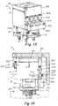
- FIG. 13-14 another cooling device 505 according to the invention is shown where the distally extending arm 502 moves radially toward and away from the actuator housing bodies 12, 12a and axis A.
- a cooling device 505 arrangement can be provided for exploiting the side-to-side or radial movement SS that the actuator 10 travels relative to the clamp plate 80 when the system is assembled in a cooled state and then subsequently the manifold 20 is heated to an elevated temperature.
- the heating of the manifold 20 subsequent to assembly of all of the clamp plate 80, mold 300, manifold 20, actuator 10 and cooling devices 500, 505 results in the actuator moving side to side relative to the clamp plate 80.
- Such side-to-side or radial movement SS in the left or lateral direction L relative to the drive axis A of the actuator can be accounted for prior to assembly such that the distal end surface 502a can be brought into compressed contact with the complementary mating surface 80a of the clamp plate with resilient compression being maintained by the spring 506a disposed between the proximal base or member 504 and the heat transmission plate or element 502.
- the surface 502a travels toward and away from the housing bodies 12, 12a when compressed and when compression is released.
- Figs. 1-12 embodiments show cooling device 500 arrangements where the distal arm 502 is adapted to move back and forth along a path of travel that is generally upstream and downstream or generally parallel to the drive axis A of the actuator or valve pin 17
- the proximal base member 504 is heat transmissively interconnected to or engaged with the distal member 502 via a heat transmissive rod 507, the downstream end of which 507d is slidably mounted within a complementary precision bore 504pb that is drilled within the distal mount member 502 such that the downstream end 507d of the rod 507 is engaged in heat transmissive intimate contact with an interior surface 504pbs of the bore 504pb.
- the upstream end 507us of the rod 507 is screwably connected to the distal member 502 into a complementary aperture within distal member 502 such that when the member 502 travels through Q the downstream end 507d is slidably moved along the path of travel Q together with movement of distal member 502.
- the upstream ends 507u of the heat transmissive rods 507 can conversely be slidably mounted within complementary bores 502pb provided in distal member 502 such that the exterior surface of the upstream end 507u of the rod 507 is slidably and heat transmissively engaged against the interior surface 502pbs of the bore 502pb.
- the downstream end 507d of the rod 507 is screwably connected to proximal mount member 504 such that when the member 502 travels through Q the upstream end 507u is slides along the interior surface 502pbs of the bore 502pb as member 502 travels through the path of travel Q.
- rods or tubes 507, 517r are preferably slidably mounted to or within one of the proximal base or member 504 and the distal arm or member 502 and rigidly interconnected to the other of the proximal base or member 504 and the distal arm or member 502.
- the rods 507ir are formed integrally together with and as a part of the body of the distal member 502, the outside surface 507os of the rods 507ir being engaged and slidable against the interior surface 504pbs of the receiving bores 504pb within the proximal mounts 504.
- the distal member 502 is spring loaded by spring 506 that disposed between the distal 502 and proximal 504 heat transmissive members.
- one or the other of the distal 502 and proximal 504 members can have one or more highly heat conductive tube members that contain a heat conductive fluid 517a, 517b, 517c, 517d embedded or mounted within a complementary receiving bore drilled into the members 502 or 504.
- one or more of the rods or tubes 507 can comprise and be adapted to contain a heat conductive fluid such as tube 517r shown in Figs. 5D, 5E, 5F, 5G , 5J, 5K .
- Such heat conductive tubes 517a, 517b, 517c, 517d are comprised of a tubular member or wall that itself is comprised of a material that is highly heat conductive such as copper, aluminum, gold, platinum or the like.
- the tubular member or wall forms a hollow interior tube cavity that contains a highly heat conductive fluid such as water, methanol or the like and also preferably further typically contains a wick that facilitates flow of the heat conductive fluid within and through the length of the cavity of the tube.
- Such heat conductive tubes facilitate the transmission of heat between the actuator housing 12, the proximal member 504 and the distal member.
- An example of the structure and configuration of such heat conductive tubes is disclosed in U.S. Patent No. 4,500,279 .
- heat conductive tubes 517ah can be embedded within the body of the actuator housing 12 as shown in Fig. 5F, 5G in the same manner as described above where the tubes 517a, 517b, 517c, 517d are embedded within members 502 or 504.
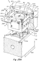
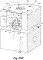
- the actuator 12 of the apparatus 5 has a pair of cooling devices each having a base member 504aa.
- One of the two cooling devices 500 has cylindrical slots 504pb, 504pba that receive a complementary rod shaped member 507m comprised of an upper rod portion 507u connected to a lower rod portion 507d.
- the upper 507u and lower 507d portions of rod member 507m, Figs. 25F, 25G are connected to each other and are both respectively slidably mounted within the complementary slots 504pb, 504pba for upstream and downstream movement UD.
- the configuration of the upper and lower 507u, 507d rod portions of the rod 507m is adapted so that the outside surfaces 507us, 507ds of the rod 507m are in slidable heat conductive engagement with the inside surfaces 504pbs, 504pbsa of the base member 504aa.
- the base member 504aa is mounted in heat conductive engagement with the outside surface of actuator housing 12.
- the base member 504aa is mounted such that it is spaced 121s a lateral distance 12ld from the axis A of the valve pin 17 and housing 12 whereby the surface 12ls and the base member 504aa are laterally spaced apart from direct heat conductive communication with the heat manifold 20.
- rods 507, 507m are mounted such that the rod 507m is spring load biased via spring 506 which exerts upstream directed force UF to urge the distal end surface 507a of the rod 507m into contact heat conductive engagement with a surface 80a of the top clamp plate 80.
- rods 507, 507m can comprise a heat conductive, fluid containing tube that are comprised of a material that is highly heat conductive such as copper, aluminum, gold, platinum and preferably contain a highly heat conductive fluid such as water, methanol or the like that facilitates the transmission of heat between the actuator housing 12, the proximal member 504, the walls of the tube 507m and the clamp plate 80.
- proximal heat conducting member 502 in such an embodiment where the rods 507, 507m comprise a heat pipe or tube, a distal end surface 507a of the rod or tube engages a surface 80a under compression via a spring load from spring 506 or otherwise.
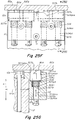
- the other cooling device of the Figs. 25A-25G embodiment comprises a base member 504aa in which a rectangular shaped distal arm or member 502 is slidably mounted in a complementarily shaped slot 504sb.
- the rectangular arm or member 502 is connected to rods 507 having a lower rod member 507d that are slidably received within complementary slots 504pb.
- the outside surfaces 507ds of the lower rod 507d portion, Fig. 25E are in slidable heat conductive engagement with the inside surfaces 504pbs of the base member 504aa.
- the distal rectangular heat conducting member 502 is slidably received within the complementary receiving aperture 504sb such that the outside surface 502s of distal arm 502 is in slidable heat conductive engagement with the inside surface 504is of the slot 504sb.
- the outside surface 502s of the distal arm 502 is also preferably mounted such that surface 502s is in slidable heat conductive engagement with the outside surface 12as of the upstream actuator member 12a and surface 12ls.
- the base member 504aa is mounted in heat conductive engagement with the outside surface 121s of actuator housing 12.
- the slidable mounting rod 507, 507d is mounted such that the rod 507 is spring load biased via spring 506 which exerts upstream directed force UF to urge the distal end surface 502a of the distal arm 502 into heat conductive engagement with a surface 80a of the top clamp plate 80.
- Figs. 25A - 25C show an assembly of the Fig. 25A actuator 12 with the pair of cooling devices 500 attached to the actuator housing together with a manifold 20 and a top clamp plate 80.
- the top clamp plate 80 is formed with a receiving aperture 80ra for insertion of the actuator 12 and cooling device subassembly that enables the actuator to be mounted on the manifold 20 and surrounded by the top clamp plate as shown.
- the upstream end of the top clamp plate 80 has a recess 80r formed in a complementary configuration to a plate 80p that is insertable within the recess 80r in an upstream position relative to the actuator housing 12 and its attached cooling devices 500 such that the distal end surfaces 502a of the heat transmissive rods 507m and the heat transmissive block 502, Figs. 25A-25G , engage the undersurface 80a of the clamp plate 80p under spring loaded compression.
- the plate 80p is readily attachable to and detachable from the upstream end surface of the clamp plate 80 via screws or bolts 80t after the actuator 12 with attached cooling devices 50 has been inserted in the receiving aperture 80ra and mounted on the manifold 20.
Landscapes
- Engineering & Computer Science (AREA)
- Manufacturing & Machinery (AREA)
- Mechanical Engineering (AREA)
- Physics & Mathematics (AREA)
- Thermal Sciences (AREA)
- Moulds For Moulding Plastics Or The Like (AREA)
- Injection Moulding Of Plastics Or The Like (AREA)
- Cooling Or The Like Of Electrical Apparatus (AREA)
- Casting Or Compression Moulding Of Plastics Or The Like (AREA)
- Cooling Or The Like Of Semiconductors Or Solid State Devices (AREA)
Claims (23)
- Spritzgießvorrichtung (5) mit einer Klemmplatte (80), einem geheizten Verteiler (20), einem Aktuator (10), der mit einem Ventilstift (17) mit einer Achse (A) verbunden ist, einer Form (300) und einer Kühlvorrichtung (500), die den Aktuator (10) kühlt, wobei im montierten Zustand die Klemmplatte (80) stromaufwärts von der Form (30) montiert und der Verteiler (20) zwischen der Klemmplatte und der Form (30) angeordnet ist,
wobei die Kühlvorrichtung (500) aufweist:eine Wärmeübertragungseinrichtung mit einer proximalen Basis oder einem proximalen Element (504), die/das aus einem wärmeleitenden Material besteht, und mit einem distalen Arm oder Element (502), der/das aus einem wärmeleitenden Material besteht, wobei der distale Arm oder das distale Element (502) durch eine oder mehrere federbelastbare Verbindungen (506) auf oder an der proximalen Basis oder dem proximalen Element (504) montiert ist, wobei der distale Arm oder das distale Element (502) eine distale Endfläche (502a) für einen Eingriff mit der Klemmplatte (80, 80a) unter einer Federbelastung und eine proximale Fläche (502b) zum Übertragen von Wärme von der proximalen Fläche zur distalen Endfläche (502a) aufweist,wobei die Feder oder die federbelastbare Verbindung (506) einen Masseanteil oder -prozentsatz aufweist, der die Feder (506) zwischen dem proximalen (504) und dem distalen (502) Element im Wesentlichen nicht wärmeleitfähig macht, undwobei die Klemmplatte, die Form (300), der Verteiler, der Aktuator und die Wärmeübertragungseinrichtung in einer Anordnung zusammen montierbar sind, bei der die federbelastbare Verbindung (506) gespannt ist, so dass die distale Endfläche (502a) des distalen Arms oder Elements (502) zumindest dann in einen komprimierten Eingriff mit der Klemmplatte (80, 80a) gezwungen wird, wenn der Verteiler auf eine erhöhte Betriebstemperatur erwärmt ist;dadurch gekennzeichnet, dassdas distale Element (502) eine proximale Außenfläche (502b) aufweist, die dazu eingerichtet ist, mit einer komplementären Fläche (12ls, 12as) des Gehäusekörpers (12, 12a) des Aktuators (10) in Gleiteingriff zu kommen, so dass eine Wärmeleitung zwischen dem Gehäusekörper (12, 12a) und dem distalen Arm oder Element (502) erzielt wird. - Vorrichtung nach Anspruch 1, wobei die Masse der federbelastbaren Verbindung derart ausgewählt ist, dass die Wärmeleitung zwischen dem proximalen und dem distalen Arm oder Element über oder durch die Feder oder die federbelastbare Verbindung (506) minimiert wird oder ein minimales Maß an Wärmeleitung zwischen dem proximalen und dem distalen Arm oder Element ermöglicht oder vermittelt wird.
- Vorrichtung nach einem der vorhergehenden Ansprüche, wobei die Masse der federbelastbaren Verbindung (506) weniger als etwa 5 Gramm beträgt.
- Vorrichtung nach einem der vorhergehenden Ansprüche, wobei die Feder oder die federbelastbare Verbindung (506) Eingriffsflächen (506es) aufweist, die mit komplementären gegenüberliegenden Eingriffsflächen (504us, 502us) des proximalen (504) und des distalen (502) Elements in Eingriff stehen, die eine ausgewählte Eingriffsfläche aufweisen, die derart ist, dass die Feder (506) zwischen dem proximalen und dem distalen Arm oder Element im Wesentlichen nicht wärmeleitend ist.
- Vorrichtung nach einem der vorhergehenden Ansprüche, wobei die Fläche des Eingriffs oder Kontakts zwischen den Eingriffsflächen (506es) und einer oder beiden der komplementären gegenüberliegenden Eingriffsflächen (504us oder 502us) die Wärmeleitung zwischen den Elementen (504 und 502) über oder durch die Feder oder die federbelastbare Verbindung (506) minimiert oder ein minimales Maß an Wärmeleitung zwischen den Elementen ermöglicht oder vermittelt wird.
- Vorrichtung nach einem der vorhergehenden Ansprüche, wobei die Fläche des Eingriffs oder Kontakts zwischen den Eingriffsflächen (506es) und einer oder beiden der komplementären gegenüberliegenden Eingriffsflächen (504us oder 502us) kleiner ist als etwa 10 Quadratmillimeter.
- Vorrichtung nach einem der vorhergehenden Ansprüche, wobei der Aktuator (10) einen Gehäusekörper (12) aufweist, der in wärmeleitendem Kontakt entlang der Achse A an einer oder mehreren Aktuatorhalterungen (50, 60, 803) montiert ist, die stromabwärts in wärmeleitender Verbindung oder in wärmeleitendem Kontakt mit oder auf dem Verteiler entlang der Achse montiert sind.
- Vorrichtung nach einem der vorhergehenden Ansprüche, ferner mit einem oder mehreren wärmeleitenden Rohren (517a, 517b, 517c, 517d), die eine wärmeleitende Flüssigkeit enthalten und im proximalen (504) und/oder im distalen (502) Element eingebettet sind.
- Vorrichtung nach einem der vorhergehenden Ansprüche, wobei das distale (502) und das proximale (504) Element durch wärmeübertragende Stäbe (507) oder Rohre (517r), die eng mit den Elementen (502, 504) in Eingriff stehen, wärmeleitend miteinander verbunden sind oder in Eingriff stehen.
- Vorrichtung nach einem der vorhergehenden Ansprüche, ferner mit einem oder mehreren hohlen wärmeleitenden Rohren (517ah) mit einem Hohlraum, der wärmeleitendes Fluid enthält, wobei das eine oder die mehreren Rohre (517ah) in den Körper des Gehäuses des Aktuators (10, 12) eingebettet sind.
- Vorrichtung nach einem der vorhergehenden Ansprüche, wobei das distale Element (502) eine proximale Außenfläche (502b) aufweist, die dazu eingerichtet ist, mit einer komplementären Fläche (12ls, 12as) des Gehäusekörpers (12, 12a) des Aktuators (10) in Gleiteingriff zu kommen, so dass zwischen dem Gehäusekörper (12, 12a) und dem distalen Arm oder Element (502) Wärme übertragen wird, wobei die distale Endfläche (502a) des distalen Arms oder Elements durch eine Gleitbewegung der proximalen Außenfläche (502b) des distalen Arms oder Elements (502) auf der komplementären Fläche (12ls, 12as) des Aktuators zum Aktuator (10) hin und von diesem weg bewegbar ist.
- Vorrichtung nach einem der vorhergehenden Ansprüche, wobei die federbelastete Verbindung (506) dazu eingerichtet ist, die distale Endfläche (502a) des distalen Arms oder Elements in eine Kompression von mindestens 0,07 kg pro Quadratzentimeter (1 psi) mit der Klemmplatte zu zwingen.
- Vorrichtung nach einem der vorhergehenden Ansprüche, wobei die laterale Fläche (121s) und die proximale Basis oder das proximale Element (504) lateral von einer direkten wärmeleitenden Verbindung mit dem erwärmten Verteiler (20) beabstandet (12ld) sind.
- Vorrichtung nach einem der vorhergehenden Ansprüche, wobei die Klemmplatte gekühlt ist.
- Vorrichtung nach einem der vorhergehenden Ansprüche, wobei die Klemmplatte, die Form, der Verteiler, der Aktuator und die Kühlvorrichtung in einer Anordnung montiert sind, bei der die Feder (506a) elastisch bis zu einem Maximum von etwa 3 mm komprimiert ist, wodurch die distale Endfläche (502a) des distalen Arms oder Elements in einen komprimierten Eingriff mit der Klemmplatte (80a) gezwungen wird.
- Vorrichtung nach einem der vorhergehenden Ansprüche, wobei die Vorrichtung zwei oder mehr separate Kühlvorrichtungen aufweist, die jeweils einen distalen Arm oder ein distales Element (502) aufweisen, der/das über eine federbelastbare Verbindung an einer proximalen Basis oder einem proximalen Element (504) montiert ist, wobei jede separate Kühlvorrichtung separat am Gehäusekörper (12, 12a) des Aktuators montiert ist und separat zusammen mit der Klemmplatte, der Form, dem Aktuator und dem Verteiler montierbar ist, so dass die distale Endfläche des distalen Arms oder Elements jeder separaten Kühlvorrichtung sich unter der federbelastbaren Verbindung (506) zwischen jedem separaten distalen Endarm (502) und der proximalen Basis oder dem proximalen Element (504) in einem komprimierten Eingriff mit der Klemmplatte befindet.
- Vorrichtung nach einem der vorhergehenden Ansprüche, ferner mit einer Halterung (803), die das Aktuatorgehäuse (19) von einem direkten Kontakt mit dem Verteiler trennt, wobei die Halterung gekühlt wird und eine stromaufwärtsseitige Montagefläche aufweist, die mit einer komplementären Montagefläche (12d) des Aktuators (10) wärmeleitend verbunden ist, und eine stromabwärtsseitige Montagefläche, die mit dem Verteiler (20) wärmeleitend verbunden ist.
- Vorrichtung nach einem der vorhergehenden Ansprüche, wobei die Halterung aus einem wärmeleitenden Metall besteht, das auf eine Temperatur von weniger als etwa 65 Grad Celsius (150 Grad Fahrenheit) abgekühlt wird.
- Vorrichtung nach einem der vorhergehenden Ansprüche, wobei der Aktuator (10) mit einer Ventilstift (17) verbunden ist, der an dem Verteiler montiert ist und sich durch eine Fluidmaterialzufuhröffnung (22) im Verteiler (20) erstreckt.
- Vorrichtung nach einem der vorhergehenden Ansprüche, wobei die proximale Basis oder das proximale Element (504) starr in wärmeleitendem Kontakt an der lateral beabstandeten Fläche (12ls) des Gehäusekörpers (12, 12a) befestigt ist.
- Vorrichtung nach einem der vorhergehenden Ansprüche, wobei der distale Arm oder das distale Element (502, 502b) am Aktuator derart befestigt ist, dass der Arm (502, 502b) in gleitendem wärmeleitendem Kontakt mit der lateralen Fläche (121s, 12as) des Gehäusekörpers angeordnet ist.
- Vorrichtung nach einem der vorhergehenden Ansprüche, wobei der distale Arm oder das distale Element eine Stange (502r) aufweist, die in einer komplementären Öffnung (12bo) gleitend angeordnet ist, die im Gehäusekörper (12, 12a) des Aktuators (10) ausgebildet ist, wobei die komplementäre Öffnung (12bo) und die Stange (502r) derart konfiguriert sind, dass eine Außenfläche (502b) der Stange (502r) in wärmeleitendem Kontakt mit einer Innenfläche (12si, 12asi) der komplementären Öffnung (12bo) in Gleiteingriff steht.
- Verfahren zum Kühlen eines Aktuators in einer Spritzgießvorrichtung (5), die eine Klemmplatte (80), einen geheizten Verteiler (20), einen Aktuator (10), der mit einem Ventilstift (17) mit einer Achse (A) verbunden ist, und eine Form (300) aufweist, wobei im montierten Zustand die Klemmplatte (80) stromaufwärts von der Form (30) montiert ist, der Verteiler (20) zwischen der Klemmplatte und Form angeordnet ist, der Aktuator (10) einen Gehäusekörper (12) aufweist, der in wärmeleitendem Kontakt entlang der Achse (A) an einer oder mehreren Aktuatorhalterungen (50, 60, 803) montiert ist, die stromabwärts in einer wärmeleitenden Verbindung oder in wärmeleitendem Kontakt mit oder auf dem Verteiler entlang der Achse (A) montiert sind,
wobei:eine Kühlvorrichtung (500) an einer Fläche (12ls) des Gehäusekörpers (12) montiert ist und ein distales Element (502) aufweist, das eine proximale Außenfläche (502b) aufweist, die dazu eingerichtet ist, mit einer komplementären Fläche (121s, 12as) des Gehäusekörpers (12, 12a) des Aktuators (10) in Gleiteingriff zu kommen, so dass zwischen dem Gehäusekörper (12, 12a) und dem distalen Arm oder Element (502) eine Wärmeleitung auftritt, wobei die Kühlvorrichtung eine proximale Basis oder ein proximales Elements (504) aufweist, das aus einem wärmeleitenden Material besteht, und einen distalen Arm oder ein distales Element (502), das aus einem wärmeleitenden Material besteht, wobei der distale Arm oder das distale Element (502) durch eine federbelastbare Verbindung oder einen federbelastbaren Eingriff (506) auf oder an der proximalen Basis oder dem proximalen Element (504) montiert ist, wobei der distale Arm oder das distale Element (502) eine distale Endfläche (502a) für einen Eingriff mit der Klemmplatte (80, 80a) unter einer Federbelastung aufweist und eine proximale Fläche (502b) zum Übertragen von Wärme von der proximalen Fläche zur distalen Endfläche (502a),wobei die Feder oder die federbelastbare Verbindung (506) einen Masseanteil oder -prozentsatz aufweist, der die Feder (506) zwischen dem proximalen (504) und dem distalen (502) Element im Wesentlichen nicht wärmeleitfähig macht, undwobei die Klemmplatte, die Form (300), der Verteiler, der Aktuator und die Wärmeübertragungseinrichtung in einer Anordnung zusammen montiert werden, bei der die federbelastbare Verbindung (506) gespannt ist, so dass die distale Endfläche (502a) des distalen Arms oder Elements (502) zumindest dann in einen komprimierten Eingriff mit der Klemmplatte (80) gezwungen wird, wenn der Verteiler auf eine erhöhte Betriebstemperatur erwärmt wird.
Applications Claiming Priority (5)
| Application Number | Priority Date | Filing Date | Title |
|---|---|---|---|
| US201562135871P | 2015-03-20 | 2015-03-20 | |
| US201562154320P | 2015-04-29 | 2015-04-29 | |
| US201562170937P | 2015-06-04 | 2015-06-04 | |
| US201562192815P | 2015-07-15 | 2015-07-15 | |
| PCT/US2016/018042 WO2016153632A1 (en) | 2015-03-20 | 2016-02-16 | Actuator cooling apparatus and method |
Publications (2)
| Publication Number | Publication Date |
|---|---|
| EP3247546A1 EP3247546A1 (de) | 2017-11-29 |
| EP3247546B1 true EP3247546B1 (de) | 2019-08-07 |
Family
ID=55456898
Family Applications (9)
| Application Number | Title | Priority Date | Filing Date |
|---|---|---|---|
| EP19163620.8A Active EP3581359B1 (de) | 2015-03-20 | 2016-02-08 | Aktuatorkühlvorrichtung und -verfahren |
| EP20177950.1A Withdrawn EP3744498A1 (de) | 2015-03-20 | 2016-02-08 | Aktuatorkühlvorrichtung und -verfahren |
| EP16708252.8A Active EP3240666B1 (de) | 2015-03-20 | 2016-02-08 | Kühlvorrichtung für aktuator und verfahren |
| EP16713646.4A Active EP3247546B1 (de) | 2015-03-20 | 2016-02-16 | Aktuatorkühlvorrichtung und -verfahren |
| EP18151044.7A Active EP3326777B1 (de) | 2015-03-20 | 2016-02-25 | Aktuatorkühlverfahren |
| EP16713153.1A Active EP3271130B1 (de) | 2015-03-20 | 2016-02-25 | Aktuatorkühlvorrichtung und -verfahren |
| EP18186892.8A Active EP3412425B1 (de) | 2015-03-20 | 2016-02-25 | Aktuatorkühlvorrichtung und -verfahren |
| EP16711394.3A Not-in-force EP3271129B1 (de) | 2015-03-20 | 2016-02-25 | Aktuatorkühlvorrichtung |
| EP16711393.5A Active EP3247545B1 (de) | 2015-03-20 | 2016-02-25 | Aktuatorkühlvorrichtung und -verfahren |
Family Applications Before (3)
| Application Number | Title | Priority Date | Filing Date |
|---|---|---|---|
| EP19163620.8A Active EP3581359B1 (de) | 2015-03-20 | 2016-02-08 | Aktuatorkühlvorrichtung und -verfahren |
| EP20177950.1A Withdrawn EP3744498A1 (de) | 2015-03-20 | 2016-02-08 | Aktuatorkühlvorrichtung und -verfahren |
| EP16708252.8A Active EP3240666B1 (de) | 2015-03-20 | 2016-02-08 | Kühlvorrichtung für aktuator und verfahren |
Family Applications After (5)
| Application Number | Title | Priority Date | Filing Date |
|---|---|---|---|
| EP18151044.7A Active EP3326777B1 (de) | 2015-03-20 | 2016-02-25 | Aktuatorkühlverfahren |
| EP16713153.1A Active EP3271130B1 (de) | 2015-03-20 | 2016-02-25 | Aktuatorkühlvorrichtung und -verfahren |
| EP18186892.8A Active EP3412425B1 (de) | 2015-03-20 | 2016-02-25 | Aktuatorkühlvorrichtung und -verfahren |
| EP16711394.3A Not-in-force EP3271129B1 (de) | 2015-03-20 | 2016-02-25 | Aktuatorkühlvorrichtung |
| EP16711393.5A Active EP3247545B1 (de) | 2015-03-20 | 2016-02-25 | Aktuatorkühlvorrichtung und -verfahren |
Country Status (4)
| Country | Link |
|---|---|
| US (2) | US10005215B2 (de) |
| EP (9) | EP3581359B1 (de) |
| CN (7) | CN107567377B (de) |
| WO (5) | WO2016153608A1 (de) |
Families Citing this family (29)
| Publication number | Priority date | Publication date | Assignee | Title |
|---|---|---|---|---|
| US10166709B2 (en) | 2011-11-23 | 2019-01-01 | Synventive Molding Solutions, Inc. | Actuator cooling apparatus and method |
| US10543629B2 (en) | 2014-12-11 | 2020-01-28 | Inglass S.P.A. | Method and apparatus for injection molding of plastic materials |
| EP3581359B1 (de) * | 2015-03-20 | 2021-08-18 | Synventive Molding Solutions, Inc. | Aktuatorkühlvorrichtung und -verfahren |
| US11007695B2 (en) | 2015-03-20 | 2021-05-18 | Synventive Molding Solutions, Inc. | Actuator cooling apparatus and method |
| WO2019100085A1 (en) | 2017-11-14 | 2019-05-23 | Synventive Molding Solutions, Inc. | Actuator with eccentric pin drive |
| WO2018089243A1 (en) | 2016-11-14 | 2018-05-17 | Synventive Molding Solutions, Inc. | Actuator cooling apparatus and method |
| AT517390A1 (de) | 2015-07-03 | 2017-01-15 | Sonderhoff Engineering Gmbh | Dosiervorrichtung für flüssigen Kunststoff |
| CN108068272A (zh) * | 2016-11-18 | 2018-05-25 | 柳道万和(苏州)热流道系统有限公司 | 缸体组件及具有其的热流道系统 |
| WO2018169819A1 (en) | 2017-03-16 | 2018-09-20 | Synventive Molding Solutions, Inc. | Injection molding apparatus |
| WO2018175362A1 (en) | 2017-03-20 | 2018-09-27 | Synventive Molding Solutions, Inc. | Valve pin positions and velocity control method and apparatus |
| WO2018183810A1 (en) | 2017-03-31 | 2018-10-04 | Synventive Molding Solutions, Inc. | Rotary valve |
| CN108724613A (zh) * | 2017-04-14 | 2018-11-02 | 柳道万和(苏州)热流道系统有限公司 | 缸体组件及具有其的热流道系统 |
| CN110461566B (zh) | 2017-04-18 | 2022-01-11 | 圣万提注塑工业(苏州)有限公司 | 注射循环期间的线性到线性阀销驱动 |
| CN110520269B (zh) | 2017-04-26 | 2021-11-30 | 圣万提注塑工业(苏州)有限公司 | 具有排气口的双密封阀销尖端 |
| EP3679414A4 (de) * | 2017-09-08 | 2021-05-05 | Commscope Technologies LLC | Wärmeableitgehäuse |
| CN108381876B (zh) * | 2018-03-08 | 2020-05-12 | 柳道万和(苏州)热流道系统有限公司 | 阀针式热流道缸 |
| US11618194B2 (en) * | 2018-03-13 | 2023-04-04 | Inglass S.P.A. | Apparatus for injection molding of plastic materials |
| IT201800004581A1 (it) * | 2018-04-16 | 2019-10-16 | Apparecchiatura di stampaggio ad iniezione di materie plastiche | |
| CN113165240B (zh) | 2018-08-17 | 2023-03-28 | 圣万提注塑工业(苏州)有限公司 | 穿过注射成型流动通道的中断流 |
| WO2020176479A1 (en) | 2019-02-25 | 2020-09-03 | Synventive Molding Solutions, Inc. | Cooled electric actuator controlled injection |
| US20200316837A1 (en) | 2019-04-02 | 2020-10-08 | Synventive Molding Solutions, Inc. | Nozzle Heater |
| CN114025936B (zh) | 2019-05-28 | 2022-11-29 | 圣万提注塑工业(苏州)有限公司 | 用于阀销的部分旋转偏心驱动 |
| CN113811431B (zh) | 2019-08-20 | 2023-10-13 | 圣万提注塑工业(苏州)有限公司 | 具有集成致动器电子驱动装置的注射成型设备 |
| WO2021062523A1 (en) | 2019-10-04 | 2021-04-08 | Husky Injection Molding Systems Ltd. | Stabilized adaptive hydraulic system pressure in an injection molding system |
| WO2021080767A1 (en) | 2019-10-21 | 2021-04-29 | Synventive Molding Solutions, Inc. | Electric actuator drive for injection molding flow control |
| EP4103387A1 (de) | 2020-02-20 | 2022-12-21 | Synventive Molding Solutions, Inc. | Sequentielle einspritzung in mehrere formhohlräume |
| EP4175812A1 (de) | 2020-07-01 | 2023-05-10 | Synventive Molding Solutions, Inc. | Verfahren und vorrichtung zur kontrollierten flüssigkeitseinspritzung |
| WO2022076782A1 (en) | 2020-10-09 | 2022-04-14 | Synventive Molding Solutions, Inc. | Spring cushioned valve pin |
| CN116685451A (zh) | 2020-12-08 | 2023-09-01 | 圣万提注塑工业有限公司 | 带有冷却集成执行器电驱动器的注射成型装置 |
Family Cites Families (33)
| Publication number | Priority date | Publication date | Assignee | Title |
|---|---|---|---|---|
| US650401A (en) | 1899-11-03 | 1900-05-29 | Isaac W Lamb | Trunk-lid brace. |
| US4500279A (en) | 1983-07-06 | 1985-02-19 | Kona Corporation | Heat pipe manifold system |
| CA2010855C (en) * | 1990-02-23 | 1999-07-27 | Jobst Ulrich Gellert | Injection molding system having spring biased nozzles |
| CA2010961C (en) * | 1990-02-27 | 1997-03-11 | Harald Schmidt | Injection molding manifold having a pair of cooling bores on opposite sides of the melt passage |
| US6361300B1 (en) | 1998-04-21 | 2002-03-26 | Synventive Molding Solutions, Inc. | Manifold system having flow control |
| US6062840A (en) | 1997-09-02 | 2000-05-16 | Dynisco Hotrunners, Inc. | Hot runner system for coinjection molding |
| US6309208B1 (en) | 1997-06-13 | 2001-10-30 | Synventive Molding Solutions, Inc. | Apparatus for proportionally controlling fluid delivery to a mold |
| US5894025A (en) | 1997-06-13 | 1999-04-13 | Kona Corporation | Valve pin actuator |
| US6294122B1 (en) | 1998-06-26 | 2001-09-25 | Synventive Molding Solutions, Inc. | Electric actuator for a melt flow control pin |
| US6287107B1 (en) | 1997-09-02 | 2001-09-11 | Synventive Molding Solutions, Inc. | Apparatus for proportionally controlling fluid delivery to a mold |
| US6464909B1 (en) | 1998-04-21 | 2002-10-15 | Synventive Molding Solutions, Inc. | Manifold system having flow control |
| US7029268B2 (en) | 2001-12-26 | 2006-04-18 | Synventive Molding Solutions, Inc. | Non-coaxial injection molding valve flow control |
| US7234929B2 (en) | 1999-09-21 | 2007-06-26 | Synventive Molding Solutions, Inc. | Injection molding flow control apparatus and method |
| US6343925B1 (en) * | 2000-04-14 | 2002-02-05 | Husky Injection Molding Systems, Ltd. | Hot runner valve gate piston assembly |
| EP1223018B1 (de) | 2001-01-10 | 2005-05-25 | Synventive Molding Solutions B.V. | Spritzgiessvorrichtung mit einer gekühlten Führungsbüchse für eine Ventilnadel |
| JP2002374653A (ja) * | 2001-04-13 | 2002-12-26 | Namu:Kk | 電動式アクチュエータ |
| AU2003303887B2 (en) * | 2003-02-04 | 2007-04-26 | Husky Injection Molding Systems Ltd. | Hot runner manifold system |
| CA2421801C (en) * | 2003-03-13 | 2010-02-23 | Denfred Holdings Ltd. | Automatic valve assembly for a water cooler reservoir |
| WO2005113215A1 (en) * | 2004-05-14 | 2005-12-01 | University Of Massachusetts | Methods and devices for melt pressure regulation |
| US7329112B2 (en) | 2005-01-04 | 2008-02-12 | Plastic Engineering & Technical Services, Inc. | Injection molding system for injection molding a plurality of materials |
| US20070119504A1 (en) * | 2005-11-28 | 2007-05-31 | Yudo Co. Ltd. | Heat dissipating apparatus for cylinders of injection molding machines |
| US10223903B2 (en) | 2010-09-28 | 2019-03-05 | Icontrol Networks, Inc. | Integrated security system with parallel processing architecture |
| EP2200799A4 (de) * | 2007-10-22 | 2012-08-29 | Mold Masters 2007 Ltd | Spritzgiessmaschine |
| CN101468511B (zh) * | 2007-12-27 | 2012-02-29 | 高建鸣 | 一种被动式针阀 |
| US8091202B2 (en) | 2009-05-06 | 2012-01-10 | Synventive Molding Solutions, Inc. | Method and apparatus for coupling and uncoupling an injection valve pin |
| CN102791460B (zh) * | 2009-12-29 | 2015-05-27 | 圣万提注塑工业有限公司 | 流体流道加热装置 |
| EP2550144B1 (de) | 2010-03-25 | 2014-05-07 | Synventive Molding Solutions, Inc. | Aktuatorhaltesystem |
| IT1400794B1 (it) * | 2010-06-24 | 2013-07-02 | Sacmi | Sistema di iniezione |
| WO2014025674A1 (en) | 2012-08-06 | 2014-02-13 | Synventive Molding Solutions, Inc., | Injection molding apparatus and method for monitoring mold halves movement |
| WO2015183332A1 (en) * | 2013-05-29 | 2015-12-03 | Synventive Molding Solutions, Inc. | Actuator cooling apparatus and method |
| US9144929B2 (en) | 2012-08-06 | 2015-09-29 | Synventive Molding Solutions, Inc. | Apparatus and method for detecting a position of an actuator piston |
| CN105555499B (zh) * | 2013-05-29 | 2017-09-12 | 圣万提注塑工业(苏州)有限公司 | 阀销位置调节器 |
| EP3581359B1 (de) * | 2015-03-20 | 2021-08-18 | Synventive Molding Solutions, Inc. | Aktuatorkühlvorrichtung und -verfahren |
-
2016
- 2016-02-08 EP EP19163620.8A patent/EP3581359B1/de active Active
- 2016-02-08 CN CN201680014238.7A patent/CN107567377B/zh active Active
- 2016-02-08 EP EP20177950.1A patent/EP3744498A1/de not_active Withdrawn
- 2016-02-08 WO PCT/US2016/016944 patent/WO2016153608A1/en not_active Ceased
- 2016-02-08 EP EP16708252.8A patent/EP3240666B1/de active Active
- 2016-02-16 EP EP16713646.4A patent/EP3247546B1/de active Active
- 2016-02-16 WO PCT/US2016/018042 patent/WO2016153632A1/en not_active Ceased
- 2016-02-16 CN CN201680011190.4A patent/CN107428055B/zh active Active
- 2016-02-16 CN CN202010505741.0A patent/CN111823526B/zh not_active Expired - Fee Related
- 2016-02-25 EP EP18151044.7A patent/EP3326777B1/de active Active
- 2016-02-25 EP EP16713153.1A patent/EP3271130B1/de active Active
- 2016-02-25 EP EP18186892.8A patent/EP3412425B1/de active Active
- 2016-02-25 CN CN201680027841.9A patent/CN107750202B/zh not_active Expired - Fee Related
- 2016-02-25 WO PCT/US2016/019469 patent/WO2016153705A1/en not_active Ceased
- 2016-02-25 WO PCT/US2016/019466 patent/WO2016153704A1/en not_active Ceased
- 2016-02-25 CN CN202011628899.3A patent/CN112976502B/zh active Active
- 2016-02-25 WO PCT/US2016/019461 patent/WO2016153703A1/en not_active Ceased
- 2016-02-25 EP EP16711394.3A patent/EP3271129B1/de not_active Not-in-force
- 2016-02-25 CN CN201680015650.0A patent/CN107530933B/zh not_active Expired - Fee Related
- 2016-02-25 CN CN201680016565.6A patent/CN107530932B/zh not_active Expired - Fee Related
- 2016-02-25 EP EP16711393.5A patent/EP3247545B1/de active Active
- 2016-07-07 US US15/204,555 patent/US10005215B2/en active Active
-
2018
- 2018-05-07 US US15/972,728 patent/US10632657B2/en not_active Expired - Fee Related
Non-Patent Citations (1)
| Title |
|---|
| None * |
Also Published As
Similar Documents
| Publication | Publication Date | Title |
|---|---|---|
| EP3247546B1 (de) | Aktuatorkühlvorrichtung und -verfahren | |
| US10889037B2 (en) | Actuator cooling apparatus and method | |
| US10625451B2 (en) | Actuator cooling apparatus and method | |
| US10953581B2 (en) | Actuator cooling apparatus and method | |
| US11052590B2 (en) | Actuator cooling apparatus and method | |
| US10005216B2 (en) | Actuator cooling apparatus and method |
Legal Events
| Date | Code | Title | Description |
|---|---|---|---|
| STAA | Information on the status of an ep patent application or granted ep patent |
Free format text: STATUS: THE INTERNATIONAL PUBLICATION HAS BEEN MADE |
|
| PUAI | Public reference made under article 153(3) epc to a published international application that has entered the european phase |
Free format text: ORIGINAL CODE: 0009012 |
|
| STAA | Information on the status of an ep patent application or granted ep patent |
Free format text: STATUS: REQUEST FOR EXAMINATION WAS MADE |
|
| 17P | Request for examination filed |
Effective date: 20170811 |
|
| AK | Designated contracting states |
Kind code of ref document: A1 Designated state(s): AL AT BE BG CH CY CZ DE DK EE ES FI FR GB GR HR HU IE IS IT LI LT LU LV MC MK MT NL NO PL PT RO RS SE SI SK SM TR |
|
| AX | Request for extension of the european patent |
Extension state: BA ME |
|
| DAV | Request for validation of the european patent (deleted) | ||
| DAX | Request for extension of the european patent (deleted) | ||
| STAA | Information on the status of an ep patent application or granted ep patent |
Free format text: STATUS: EXAMINATION IS IN PROGRESS |
|
| 17Q | First examination report despatched |
Effective date: 20180718 |
|
| GRAP | Despatch of communication of intention to grant a patent |
Free format text: ORIGINAL CODE: EPIDOSNIGR1 |
|
| STAA | Information on the status of an ep patent application or granted ep patent |
Free format text: STATUS: GRANT OF PATENT IS INTENDED |
|
| INTG | Intention to grant announced |
Effective date: 20190318 |
|
| GRAS | Grant fee paid |
Free format text: ORIGINAL CODE: EPIDOSNIGR3 |
|
| GRAA | (expected) grant |
Free format text: ORIGINAL CODE: 0009210 |
|
| STAA | Information on the status of an ep patent application or granted ep patent |
Free format text: STATUS: THE PATENT HAS BEEN GRANTED |
|
| AK | Designated contracting states |
Kind code of ref document: B1 Designated state(s): AL AT BE BG CH CY CZ DE DK EE ES FI FR GB GR HR HU IE IS IT LI LT LU LV MC MK MT NL NO PL PT RO RS SE SI SK SM TR |
|
| REG | Reference to a national code |
Ref country code: GB Ref legal event code: FG4D |
|
| REG | Reference to a national code |
Ref country code: CH Ref legal event code: EP Ref country code: AT Ref legal event code: REF Ref document number: 1163142 Country of ref document: AT Kind code of ref document: T Effective date: 20190815 |
|
| REG | Reference to a national code |
Ref country code: DE Ref legal event code: R096 Ref document number: 602016018097 Country of ref document: DE |
|
| REG | Reference to a national code |
Ref country code: IE Ref legal event code: FG4D |
|
| REG | Reference to a national code |
Ref country code: NL Ref legal event code: MP Effective date: 20190807 |
|
| REG | Reference to a national code |
Ref country code: LT Ref legal event code: MG4D |
|
| PG25 | Lapsed in a contracting state [announced via postgrant information from national office to epo] |
Ref country code: FI Free format text: LAPSE BECAUSE OF FAILURE TO SUBMIT A TRANSLATION OF THE DESCRIPTION OR TO PAY THE FEE WITHIN THE PRESCRIBED TIME-LIMIT Effective date: 20190807 Ref country code: HR Free format text: LAPSE BECAUSE OF FAILURE TO SUBMIT A TRANSLATION OF THE DESCRIPTION OR TO PAY THE FEE WITHIN THE PRESCRIBED TIME-LIMIT Effective date: 20190807 Ref country code: PT Free format text: LAPSE BECAUSE OF FAILURE TO SUBMIT A TRANSLATION OF THE DESCRIPTION OR TO PAY THE FEE WITHIN THE PRESCRIBED TIME-LIMIT Effective date: 20191209 Ref country code: SE Free format text: LAPSE BECAUSE OF FAILURE TO SUBMIT A TRANSLATION OF THE DESCRIPTION OR TO PAY THE FEE WITHIN THE PRESCRIBED TIME-LIMIT Effective date: 20190807 Ref country code: NO Free format text: LAPSE BECAUSE OF FAILURE TO SUBMIT A TRANSLATION OF THE DESCRIPTION OR TO PAY THE FEE WITHIN THE PRESCRIBED TIME-LIMIT Effective date: 20191107 Ref country code: BG Free format text: LAPSE BECAUSE OF FAILURE TO SUBMIT A TRANSLATION OF THE DESCRIPTION OR TO PAY THE FEE WITHIN THE PRESCRIBED TIME-LIMIT Effective date: 20191107 Ref country code: NL Free format text: LAPSE BECAUSE OF FAILURE TO SUBMIT A TRANSLATION OF THE DESCRIPTION OR TO PAY THE FEE WITHIN THE PRESCRIBED TIME-LIMIT Effective date: 20190807 Ref country code: LT Free format text: LAPSE BECAUSE OF FAILURE TO SUBMIT A TRANSLATION OF THE DESCRIPTION OR TO PAY THE FEE WITHIN THE PRESCRIBED TIME-LIMIT Effective date: 20190807 |
|
| REG | Reference to a national code |
Ref country code: AT Ref legal event code: MK05 Ref document number: 1163142 Country of ref document: AT Kind code of ref document: T Effective date: 20190807 |
|
| PG25 | Lapsed in a contracting state [announced via postgrant information from national office to epo] |
Ref country code: ES Free format text: LAPSE BECAUSE OF FAILURE TO SUBMIT A TRANSLATION OF THE DESCRIPTION OR TO PAY THE FEE WITHIN THE PRESCRIBED TIME-LIMIT Effective date: 20190807 Ref country code: GR Free format text: LAPSE BECAUSE OF FAILURE TO SUBMIT A TRANSLATION OF THE DESCRIPTION OR TO PAY THE FEE WITHIN THE PRESCRIBED TIME-LIMIT Effective date: 20191108 Ref country code: LV Free format text: LAPSE BECAUSE OF FAILURE TO SUBMIT A TRANSLATION OF THE DESCRIPTION OR TO PAY THE FEE WITHIN THE PRESCRIBED TIME-LIMIT Effective date: 20190807 Ref country code: AL Free format text: LAPSE BECAUSE OF FAILURE TO SUBMIT A TRANSLATION OF THE DESCRIPTION OR TO PAY THE FEE WITHIN THE PRESCRIBED TIME-LIMIT Effective date: 20190807 Ref country code: RS Free format text: LAPSE BECAUSE OF FAILURE TO SUBMIT A TRANSLATION OF THE DESCRIPTION OR TO PAY THE FEE WITHIN THE PRESCRIBED TIME-LIMIT Effective date: 20190807 Ref country code: IS Free format text: LAPSE BECAUSE OF FAILURE TO SUBMIT A TRANSLATION OF THE DESCRIPTION OR TO PAY THE FEE WITHIN THE PRESCRIBED TIME-LIMIT Effective date: 20191207 |
|
| PG25 | Lapsed in a contracting state [announced via postgrant information from national office to epo] |
Ref country code: TR Free format text: LAPSE BECAUSE OF FAILURE TO SUBMIT A TRANSLATION OF THE DESCRIPTION OR TO PAY THE FEE WITHIN THE PRESCRIBED TIME-LIMIT Effective date: 20190807 |
|
| PG25 | Lapsed in a contracting state [announced via postgrant information from national office to epo] |
Ref country code: PL Free format text: LAPSE BECAUSE OF FAILURE TO SUBMIT A TRANSLATION OF THE DESCRIPTION OR TO PAY THE FEE WITHIN THE PRESCRIBED TIME-LIMIT Effective date: 20190807 Ref country code: EE Free format text: LAPSE BECAUSE OF FAILURE TO SUBMIT A TRANSLATION OF THE DESCRIPTION OR TO PAY THE FEE WITHIN THE PRESCRIBED TIME-LIMIT Effective date: 20190807 Ref country code: AT Free format text: LAPSE BECAUSE OF FAILURE TO SUBMIT A TRANSLATION OF THE DESCRIPTION OR TO PAY THE FEE WITHIN THE PRESCRIBED TIME-LIMIT Effective date: 20190807 Ref country code: RO Free format text: LAPSE BECAUSE OF FAILURE TO SUBMIT A TRANSLATION OF THE DESCRIPTION OR TO PAY THE FEE WITHIN THE PRESCRIBED TIME-LIMIT Effective date: 20190807 Ref country code: IT Free format text: LAPSE BECAUSE OF FAILURE TO SUBMIT A TRANSLATION OF THE DESCRIPTION OR TO PAY THE FEE WITHIN THE PRESCRIBED TIME-LIMIT Effective date: 20190807 Ref country code: DK Free format text: LAPSE BECAUSE OF FAILURE TO SUBMIT A TRANSLATION OF THE DESCRIPTION OR TO PAY THE FEE WITHIN THE PRESCRIBED TIME-LIMIT Effective date: 20190807 |
|
| PG25 | Lapsed in a contracting state [announced via postgrant information from national office to epo] |
Ref country code: SK Free format text: LAPSE BECAUSE OF FAILURE TO SUBMIT A TRANSLATION OF THE DESCRIPTION OR TO PAY THE FEE WITHIN THE PRESCRIBED TIME-LIMIT Effective date: 20190807 Ref country code: CZ Free format text: LAPSE BECAUSE OF FAILURE TO SUBMIT A TRANSLATION OF THE DESCRIPTION OR TO PAY THE FEE WITHIN THE PRESCRIBED TIME-LIMIT Effective date: 20190807 Ref country code: IS Free format text: LAPSE BECAUSE OF FAILURE TO SUBMIT A TRANSLATION OF THE DESCRIPTION OR TO PAY THE FEE WITHIN THE PRESCRIBED TIME-LIMIT Effective date: 20200224 Ref country code: SM Free format text: LAPSE BECAUSE OF FAILURE TO SUBMIT A TRANSLATION OF THE DESCRIPTION OR TO PAY THE FEE WITHIN THE PRESCRIBED TIME-LIMIT Effective date: 20190807 |
|
| REG | Reference to a national code |
Ref country code: DE Ref legal event code: R097 Ref document number: 602016018097 Country of ref document: DE |
|
| PLBE | No opposition filed within time limit |
Free format text: ORIGINAL CODE: 0009261 |
|
| STAA | Information on the status of an ep patent application or granted ep patent |
Free format text: STATUS: NO OPPOSITION FILED WITHIN TIME LIMIT |
|
| PG2D | Information on lapse in contracting state deleted |
Ref country code: IS |
|
| 26N | No opposition filed |
Effective date: 20200603 |
|
| PG25 | Lapsed in a contracting state [announced via postgrant information from national office to epo] |
Ref country code: SI Free format text: LAPSE BECAUSE OF FAILURE TO SUBMIT A TRANSLATION OF THE DESCRIPTION OR TO PAY THE FEE WITHIN THE PRESCRIBED TIME-LIMIT Effective date: 20190807 |
|
| REG | Reference to a national code |
Ref country code: CH Ref legal event code: PL |
|
| GBPC | Gb: european patent ceased through non-payment of renewal fee |
Effective date: 20200216 |
|
| REG | Reference to a national code |
Ref country code: BE Ref legal event code: MM Effective date: 20200229 |
|
| PG25 | Lapsed in a contracting state [announced via postgrant information from national office to epo] |
Ref country code: MC Free format text: LAPSE BECAUSE OF FAILURE TO SUBMIT A TRANSLATION OF THE DESCRIPTION OR TO PAY THE FEE WITHIN THE PRESCRIBED TIME-LIMIT Effective date: 20190807 Ref country code: LU Free format text: LAPSE BECAUSE OF NON-PAYMENT OF DUE FEES Effective date: 20200216 |
|
| PG25 | Lapsed in a contracting state [announced via postgrant information from national office to epo] |
Ref country code: LI Free format text: LAPSE BECAUSE OF NON-PAYMENT OF DUE FEES Effective date: 20200229 Ref country code: CH Free format text: LAPSE BECAUSE OF NON-PAYMENT OF DUE FEES Effective date: 20200229 |
|
| PG25 | Lapsed in a contracting state [announced via postgrant information from national office to epo] |
Ref country code: GB Free format text: LAPSE BECAUSE OF NON-PAYMENT OF DUE FEES Effective date: 20200216 Ref country code: IE Free format text: LAPSE BECAUSE OF NON-PAYMENT OF DUE FEES Effective date: 20200216 Ref country code: FR Free format text: LAPSE BECAUSE OF NON-PAYMENT OF DUE FEES Effective date: 20200229 |
|
| PG25 | Lapsed in a contracting state [announced via postgrant information from national office to epo] |
Ref country code: BE Free format text: LAPSE BECAUSE OF NON-PAYMENT OF DUE FEES Effective date: 20200229 |
|
| PG25 | Lapsed in a contracting state [announced via postgrant information from national office to epo] |
Ref country code: MT Free format text: LAPSE BECAUSE OF FAILURE TO SUBMIT A TRANSLATION OF THE DESCRIPTION OR TO PAY THE FEE WITHIN THE PRESCRIBED TIME-LIMIT Effective date: 20190807 Ref country code: CY Free format text: LAPSE BECAUSE OF FAILURE TO SUBMIT A TRANSLATION OF THE DESCRIPTION OR TO PAY THE FEE WITHIN THE PRESCRIBED TIME-LIMIT Effective date: 20190807 |
|
| PG25 | Lapsed in a contracting state [announced via postgrant information from national office to epo] |
Ref country code: MK Free format text: LAPSE BECAUSE OF FAILURE TO SUBMIT A TRANSLATION OF THE DESCRIPTION OR TO PAY THE FEE WITHIN THE PRESCRIBED TIME-LIMIT Effective date: 20190807 |
|
| P01 | Opt-out of the competence of the unified patent court (upc) registered |
Effective date: 20230524 |
|
| PGFP | Annual fee paid to national office [announced via postgrant information from national office to epo] |
Ref country code: DE Payment date: 20260218 Year of fee payment: 11 |