EP3247582B1 - Transmission hydromécanique ayant de multiples modes de fonctionnement et méthode d'utilisation associée - Google Patents
Transmission hydromécanique ayant de multiples modes de fonctionnement et méthode d'utilisation associée Download PDFInfo
- Publication number
- EP3247582B1 EP3247582B1 EP16739836.1A EP16739836A EP3247582B1 EP 3247582 B1 EP3247582 B1 EP 3247582B1 EP 16739836 A EP16739836 A EP 16739836A EP 3247582 B1 EP3247582 B1 EP 3247582B1
- Authority
- EP
- European Patent Office
- Prior art keywords
- hydraulic
- hydraulic devices
- mode
- vane
- devices
- Prior art date
- Legal status (The legal status is an assumption and is not a legal conclusion. Google has not performed a legal analysis and makes no representation as to the accuracy of the status listed.)
- Active
Links
Images



Classifications
-
- F—MECHANICAL ENGINEERING; LIGHTING; HEATING; WEAPONS; BLASTING
- F16—ENGINEERING ELEMENTS AND UNITS; GENERAL MEASURES FOR PRODUCING AND MAINTAINING EFFECTIVE FUNCTIONING OF MACHINES OR INSTALLATIONS; THERMAL INSULATION IN GENERAL
- F16H—GEARING
- F16H47/00—Combinations of mechanical gearing with fluid clutches or fluid gearing
- F16H47/02—Combinations of mechanical gearing with fluid clutches or fluid gearing the fluid gearing being of the volumetric type
-
- B—PERFORMING OPERATIONS; TRANSPORTING
- B60—VEHICLES IN GENERAL
- B60K—ARRANGEMENT OR MOUNTING OF PROPULSION UNITS OR OF TRANSMISSIONS IN VEHICLES; ARRANGEMENT OR MOUNTING OF PLURAL DIVERSE PRIME-MOVERS IN VEHICLES; AUXILIARY DRIVES FOR VEHICLES; INSTRUMENTATION OR DASHBOARDS FOR VEHICLES; ARRANGEMENTS IN CONNECTION WITH COOLING, AIR INTAKE, GAS EXHAUST OR FUEL SUPPLY OF PROPULSION UNITS IN VEHICLES
- B60K17/00—Arrangement or mounting of transmissions in vehicles
- B60K17/04—Arrangement or mounting of transmissions in vehicles characterised by arrangement, location or kind of gearing
- B60K17/10—Arrangement or mounting of transmissions in vehicles characterised by arrangement, location or kind of gearing of fluid gearing
-
- F—MECHANICAL ENGINEERING; LIGHTING; HEATING; WEAPONS; BLASTING
- F16—ENGINEERING ELEMENTS AND UNITS; GENERAL MEASURES FOR PRODUCING AND MAINTAINING EFFECTIVE FUNCTIONING OF MACHINES OR INSTALLATIONS; THERMAL INSULATION IN GENERAL
- F16D—COUPLINGS FOR TRANSMITTING ROTATION; CLUTCHES; BRAKES
- F16D3/00—Yielding couplings, i.e. with means permitting movement between the connected parts during the drive
- F16D3/50—Yielding couplings, i.e. with means permitting movement between the connected parts during the drive with the coupling parts connected by one or more intermediate members
- F16D3/64—Yielding couplings, i.e. with means permitting movement between the connected parts during the drive with the coupling parts connected by one or more intermediate members comprising elastic elements arranged between substantially-radial walls of both coupling parts
- F16D3/68—Yielding couplings, i.e. with means permitting movement between the connected parts during the drive with the coupling parts connected by one or more intermediate members comprising elastic elements arranged between substantially-radial walls of both coupling parts the elements being made of rubber or similar material
-
- F—MECHANICAL ENGINEERING; LIGHTING; HEATING; WEAPONS; BLASTING
- F16—ENGINEERING ELEMENTS AND UNITS; GENERAL MEASURES FOR PRODUCING AND MAINTAINING EFFECTIVE FUNCTIONING OF MACHINES OR INSTALLATIONS; THERMAL INSULATION IN GENERAL
- F16D—COUPLINGS FOR TRANSMITTING ROTATION; CLUTCHES; BRAKES
- F16D31/00—Fluid couplings or clutches with pumping sets of the volumetric type, i.e. in the case of liquid passing a predetermined volume per revolution
-
- F—MECHANICAL ENGINEERING; LIGHTING; HEATING; WEAPONS; BLASTING
- F16—ENGINEERING ELEMENTS AND UNITS; GENERAL MEASURES FOR PRODUCING AND MAINTAINING EFFECTIVE FUNCTIONING OF MACHINES OR INSTALLATIONS; THERMAL INSULATION IN GENERAL
- F16D—COUPLINGS FOR TRANSMITTING ROTATION; CLUTCHES; BRAKES
- F16D31/00—Fluid couplings or clutches with pumping sets of the volumetric type, i.e. in the case of liquid passing a predetermined volume per revolution
- F16D31/06—Fluid couplings or clutches with pumping sets of the volumetric type, i.e. in the case of liquid passing a predetermined volume per revolution using pumps of types differing from those before-mentioned
-
- F—MECHANICAL ENGINEERING; LIGHTING; HEATING; WEAPONS; BLASTING
- F16—ENGINEERING ELEMENTS AND UNITS; GENERAL MEASURES FOR PRODUCING AND MAINTAINING EFFECTIVE FUNCTIONING OF MACHINES OR INSTALLATIONS; THERMAL INSULATION IN GENERAL
- F16H—GEARING
- F16H61/00—Control functions within control units of change-speed- or reversing-gearings for conveying rotary motion ; Control of exclusively fluid gearing, friction gearing, gearings with endless flexible members or other particular types of gearing
- F16H61/38—Control of exclusively fluid gearing
- F16H61/40—Control of exclusively fluid gearing hydrostatic
- F16H61/44—Control of exclusively fluid gearing hydrostatic with more than one pump or motor in operation
-
- F—MECHANICAL ENGINEERING; LIGHTING; HEATING; WEAPONS; BLASTING
- F16—ENGINEERING ELEMENTS AND UNITS; GENERAL MEASURES FOR PRODUCING AND MAINTAINING EFFECTIVE FUNCTIONING OF MACHINES OR INSTALLATIONS; THERMAL INSULATION IN GENERAL
- F16H—GEARING
- F16H61/00—Control functions within control units of change-speed- or reversing-gearings for conveying rotary motion ; Control of exclusively fluid gearing, friction gearing, gearings with endless flexible members or other particular types of gearing
- F16H61/38—Control of exclusively fluid gearing
- F16H61/40—Control of exclusively fluid gearing hydrostatic
- F16H61/44—Control of exclusively fluid gearing hydrostatic with more than one pump or motor in operation
- F16H61/444—Control of exclusively fluid gearing hydrostatic with more than one pump or motor in operation by changing the number of pump or motor units in operation
-
- F—MECHANICAL ENGINEERING; LIGHTING; HEATING; WEAPONS; BLASTING
- F16—ENGINEERING ELEMENTS AND UNITS; GENERAL MEASURES FOR PRODUCING AND MAINTAINING EFFECTIVE FUNCTIONING OF MACHINES OR INSTALLATIONS; THERMAL INSULATION IN GENERAL
- F16D—COUPLINGS FOR TRANSMITTING ROTATION; CLUTCHES; BRAKES
- F16D33/00—Rotary fluid couplings or clutches of the hydrokinetic type
-
- F—MECHANICAL ENGINEERING; LIGHTING; HEATING; WEAPONS; BLASTING
- F16—ENGINEERING ELEMENTS AND UNITS; GENERAL MEASURES FOR PRODUCING AND MAINTAINING EFFECTIVE FUNCTIONING OF MACHINES OR INSTALLATIONS; THERMAL INSULATION IN GENERAL
- F16H—GEARING
- F16H47/00—Combinations of mechanical gearing with fluid clutches or fluid gearing
- F16H47/02—Combinations of mechanical gearing with fluid clutches or fluid gearing the fluid gearing being of the volumetric type
- F16H2047/025—Combinations of mechanical gearing with fluid clutches or fluid gearing the fluid gearing being of the volumetric type the fluid gearing comprising a plurality of pumps or motors
Definitions
- the present invention relates generally to hydraulic devices, and more particularly, to hydrostatic devices that can operate as torque couplings and related systems.
- Rotary couplings are utilized in vehicles, industrial machines, and marine applications to transmit rotating mechanical power. For example, they have been used in automobile transmissions as an alternative to a mechanical clutch. Use of rotary couplings is also widespread in applications where variable speed operation and controlled start-up without shock loading of the power transmission system is desired.
- the document US 2013/067899 A1 describes an example of a hydrostatic torque converter/amplifier suitable for use in vehicle or industrial drive systems.
- the torque converter incorporates a hydraulic device such as a vane pump and is switched between coupling and decoupling modes by operating the hydraulic device in corresponding pumping and non-pumping modes.
- Document US 8584452 B2 describes an infinitely-variable, hydro-mechanical transmission using fixed displacement pumps and motors.
- two or more fixed displacement hydraulic pump/motors are mounted on a common input shaft hydraulically connected to two or more fixed hydraulic pump/motors mounted on a common output shaft
- a plurality of hydraulic devices each configured to be operable as a hydrostatic coupling and as a vane pump.
- the plurality of hydraulic devices can allow these systems to operate in various operation modes including hybrid modes that enable simultaneous vehicle drive and hydraulically driven operation (e.g. operation of a bucket while driving the vehicle forward).
- the plurality of hydraulic devices can be used with other vehicle accessories such that the vehicle can operate in a plurality of operation modes including tandem torque amplifying wheel drive mode, a tandem steady state wheel drive mode, a tandem vane pumping mode, a regenerative energy storage mode, and a regenerative energy application mode.
- the accessories used with the vehicle systems can comprise a hydraulic pump motor, an accumulator, and various vehicle auxiliary systems that are hydraulically operated.
- the fluid communicating interior portions of the system including, for example, the plurality of hydraulic devices, the plurality of accessories, and the transmission can be coated in a diamond or diamond-like carbon. This can allow more environmentally friendly hydraulic fluids such as glycol to be used by the system.
- vehicle means virtually all types of vehicles such as earth moving equipment (e.g., wheel loaders, mini-loaders, backhoes, dump trucks, crane trucks, transit mixers, etc.), waste recovery vehicles, marine vehicles, industrial equipment (e.g., agricultural equipment), personal vehicles, public transportation vehicles, and commercial road vehicles (e.g., heavy road trucks, semi-trucks, etc.).
- earth moving equipment e.g., wheel loaders, mini-loaders, backhoes, dump trucks, crane trucks, transit mixers, etc.
- waste recovery vehicles e.g., marine vehicles, industrial equipment (e.g., agricultural equipment), personal vehicles, public transportation vehicles, and commercial road vehicles (e.g., heavy road trucks, semi-trucks, etc.).
- the present inventors have recognized that traditional torque converters slip when subjected to high torque and low or no travel speed, such as when a backhoe drives forward and uses its bucket to break into a heap of material. Slippage can waste energy, lowering efficiency and creating high heat.
- Traditional hydrostatic drives are designed to provide a minimum displacement when operating as a pump and a maximum displacement when operating as a motor. Again, such operation characteristics can have very low efficiency.
- the present inventors have recognized various vehicle systems that can increase efficiency.
- the present inventors have recognized vehicle systems that can use excess energy for hydraulic function and/or to store energy for later use/power regeneration. The efficiency increases provided by the systems can allow lower power rated engines to be used.
- the engine management system can have a far better chance of offering fuel efficiency and can reduce fuel usage and emissions.
- the present inventors have also recognized that the use of a plurality of hydraulic devices, each separately capable of operation as a vane pump or torque coupling, allows for tandem system operation such as hybrid pumping and drive that can increase efficiency, reduced fuel usage, and
- Independent claim 1 defines a vehicle system and independent claim 11 defines a method of operating such a vehicle system.
- the dependent claims concern particular embodiments of the invention as claimed in the independent claims.
- the present invention relates to vehicle systems that utilizes a plurality of hydraulic devices each configured to be operable as a hydraulic coupling and as a vane pump according to claim 1.
- the system includes a plurality of input shafts, a plurality of output shafts, a power train, a torque producer coupled to the input shafts, a transmission coupled to the output shafts, a pump motor, which is coupled to the transmission by an output shaft, said output shaft being a part of one of the plurality of output shafts, a plurality of hydraulic devices, and one or more accessories.
- the plurality of hydraulic devices are configured to be operable as vane pumps in a first mode of operation and are configured to be operable as a hydraulic couplings to couple the input shafts with the output shafts in a second mode of operation.
- the plurality of hydraulic devices can be simultaneously operable as the hydraulic couplings and the vane pumps.
- the one or more accessories can be in fluid communication with the plurality of hydraulic devices and can be configured to receive a hydraulic fluid pumped from one or more the plurality of hydraulic devices when operating as the vane pumps. Further examples can include the one or more accessories comprise a plurality of accessories that are configured for operation with the hydraulic devices in the plurality of operation modes.
- the present invention relates further to a method of operating the vehicle system according to claim 11.
- the method includes controlling the plurality of hydraulic devices to operate together as either the hydraulic coupling or vane pump or controlling each of the hydraulic devices to operate independently such that at least one of the hydraulic devices operates as the hydraulic coupling and at least one of the hydraulic devices operates as the vane pump based on a plurality of vehicle operation parameters.
- the disclosed vehicle systems are applicable to various types of vehicles such as earth moving equipment (e.g., wheel loaders, mini-loaders, backhoes, dump trucks, crane trucks, transit mixers, etc.), waste recovery vehicles, marine vehicles, industrial equipment (e.g., agricultural equipment), personal vehicles, public transportation vehicles, and commercial road vehicles (e.g., heavy road trucks, semi-trucks, etc.).
- earth moving equipment e.g., wheel loaders, mini-loaders, backhoes, dump trucks, crane trucks, transit mixers, etc.
- waste recovery vehicles e.g., marine vehicles, industrial equipment (e.g., agricultural equipment), personal vehicles, public transportation vehicles, and commercial road vehicles (e.g., heavy road trucks, semi-trucks, etc.).
- FIG. 1 which does not illustrate the claimed invention but only represents an example helping to define the invention, shows a highly schematic view of a system 10 aboard a vehicle.
- the system 10 can include a torque source 12, an input shaft 3, a plurality of hydraulic devices 14, an output shaft 15, a plurality of accessories 16, a controller 18, a transmission 20, and a power train 22.
- the plurality of accessories 16 can include a pump motor 24 and one or more output shafts 26.
- the illustration of FIG. 1 represents one possible configuration (e.g., with the plurality of hydraulic devices 14 disposed before the transmission 20 and with output shafts 15 (including shaft 26) coupled to the transmission 20), with other configurations possible.
- the torque source 12 can comprise any source including, but not limited to, an engine, a flywheel, an electric motor, etc.
- the torque source 12 is coupled to one or more input shafts 13 for the plurality of hydraulic devices 14.
- the torque source 12 outputs torque/power to the plurality of hydraulic devices 14, which can selectively transmit the torque/power via the one or more output shafts 15 to the transmission 20 or another power train 22 system.
- the hydraulic devices 14 can be intelligently controlled by pilot signal(s), valve(s), etc.
- the controller 18 e.g. vehicle ECU
- the controller 18 can be configured to communicate with various systems and components of the system 10 and vehicle and can be operable to control a system operation mode (as illustrated and discussed, in reference to FIGS. 4-8 ) based on a plurality of vehicle operation parameters (e.g. deceleration, acceleration, vehicle speed, desire or need to operate various auxiliary systems including hydraulically powered systems, etc.).
- the plurality of hydraulic devices 14 can each be configured to be operable as a hydraulic coupling and as a vane pump and can be controlled to operate in a manner that provides for coupling only, coupling and vane pumping, pumping only, etc. Accordingly, each of the plurality of hydraulic devices 14 are coupled to the input shaft 13 and the output shaft 15. Additionally, FIG. 1 illustrates an example where the plurality of hydraulic devices 14 are in fluid communication with the plurality of accessories 16. FIG. 1 illustrates one of the accessories 16, the pump motor 24, which is coupled to the transmission 20 by the output shaft 26.
- the plurality of accessories 16 can comprise, for example, an accumulator, and/or one or more auxiliary systems (e.g., systems for cooling fan drives, dump boxes, power steering, compressor systems, alternator systems, braking systems, fire suppression systems, hydraulic equipment related systems, etc.).
- auxiliary systems e.g., systems for cooling fan drives, dump boxes, power steering, compressor systems, alternator systems, braking systems, fire suppression systems, hydraulic equipment related systems, etc.
- the pump motor 24 can comprise a digitally controlled piston pump.
- the pump motor 24 can be controlled by various methods including, but not limited to, electronically, pressure compensated, lever, or digitally.
- the pump motor 24 is coupled to the transmission 20 by the output shaft 26 (part of shaft 15) and can receive torque from or apply torque to the transmission 20.
- the hydraulic pump motor 24 can include a port in fluid communication with the discharge pressure of one or more of the hydraulic devices 14.
- the pump motor 24 can receive hydraulic fluid at the discharge pressure from one or more of the hydraulic devices 14 to propel the transmission 20.
- the pump motor 24 can be stroked on slightly or fully in this condition; the degree of stroke is inconsequential as there can be little inlet port pressure. Further details regarding additional operation of the pump motor 24 and system operation modes will be discussed subsequently.
- each of the plurality of hydraulic devices 14 can have a body and at least a first vane configured for movement relative to the body.
- Each hydraulic device can be adapted to retain the first vane in a retracted vane mode of operation and to release the first vane in a vane extended mode of operation in which the first vane extends to meet the body to hydraulically work fluid when the first vane is moved with respect to the body.
- the input shaft 13 and the output shaft 15 can coupled to rotate together in the vane extended mode of operation (i.e. the hydraulic devices operate as hydraulic couplings) if the output shaft 15 is not fixed or has sufficient resistance to couple.
- the input shaft 13 and output shaft 15 can be free to rotate with respect to one another in a vane extended mode of operation (i.e. the hydraulic devices operate as vane pumps) if the output shaft 15 is either fixed or has does not create sufficient resistance to entirely couple.
- a vane extended mode of operation i.e. the hydraulic devices operate as vane pumps
- one or more of the hydraulic devices 14 can operate as a hydraulic pump, and thus, operates as part of a hydraulic system for the vehicle.
- Various intelligent controls electronic, pressure compensated, lever, and/or digital
- valves, bleed valves, components, etc. can be utilized to control the direction and amount of hydraulic fluid to and from the plurality of accessories 16 and the plurality of hydraulic devices 14.
- the present systems benefit from precise control.
- programmable torque settings affected by adjustment of the pressure relief setting result in predetermined stall points.
- Such programmable stall points can be either fixed or remotely set by associating relief valve setting with a remote conventional override relief valve.
- a further benefit of precise control can be controlled acceleration or deceleration by varying relief valve settings to match desired maximum torques. In such embodiments, start and stop torques can be reduced to limit high peak torque levels that can damage machinery.
- the controller 18 can operate as a remote pressure control.
- the remote pressure control is coupled to one side of a balance piston, with pump output in fluid communication with the opposite side of the balance piston.
- the balance piston is to control whether the hydraulic device can pump hydraulic fluid. For example, if the remote pressure control is set to a pressure, the balance piston allows coupling discharge pressure to rise until the device discharge pressure is higher than the pressure, moving the balance piston to overcome the remote pressure control pressure. As the balance piston moves, it enables the device discharge to drain, such as to tank.
- the maximum, torque transmitted is remotely controllable via the remote pressure control signal
- the remote pressure control is used in addition to a primary relief valve that allows hydraulic fluid to pump in any case where a torque differential between the input shaft 13 and the output shaft 15 exceeds a predetermined threshold.
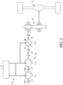
- FIG. 2 illustrates a system 110 similar in construction and arrangement to that of previously discussed system 10 ( FIG. 1 ) but with a plurality of hydraulic devices 114 arranged in series.
- FIG. 2 while not part of the claimed invention, represents a further example that helps to define the invention.
- the system 110 can include an input shaft 113, a plurality of hydraulic devices 114, an output shaft 115, an intermediate shaft 117, the plurality of accessories 16, the transmission 20, and the power train 22.
- the plurality of accessories 16 can include the pump motor 24 and the output shaft 26 as previously discussed.
- the input shaft 113 can be coupled to a torque source (not shown) and connected to a first hydraulic device 114a.
- the intermediate shaft 117 can couple the first hydraulic device 114a to at least a second hydraulic device 114b of the plurality of hydraulic devices 114.
- the output shaft 115 from the plurality of hydraulic devices 114 can be coupled to the transmission 20 and the remainder of the power train 22.
- the plurality of hydraulic devices 114 can be in fluid communication with the plurality of accessories 16 as previously discussed.
- One of the accessories 16 can comprise the pump motor 24 with the output shaft 26 (part of output shaft 115) coupled to the transmission 20 as discussed previously.
- the example of FIG. 2 illustrates the pump motor 24 as coupled to the output shaft 115, in other examples the pump motor 24 and output shaft 26 can be coupled to the transmission 20 without being coupled to the output shaft 115.
- the first hydraulic device 114a is illustrated as coupled to the second hydraulic device 114b by the intermediate shaft 117.
- a clutch or similar device can be used to disconnect and isolate the first hydraulic device 114a from the second hydraulic device 114b (or subsequent additional devices) such that one or more of the plurality of hydraulic devices 114 can be utilized as the vane pump while one or more of the plurality of hydraulic devices 114 can be utilized as the torque coupling.
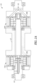
- FIG. 2A illustrates a cross-section of the plurality of hydraulic devices 114 according to one example.
- the intermediate shaft 117 can comprise a bell housing connecting the first hydraulic device 114-a to the second hydraulic device 114b.
- the input shaft 113 can comprise a thru shaft that drives both the first hydraulic device 114a and the second hydraulic device 114b.
- the first hydraulic device 114a and the second hydraulic device 114b include pump supply ports 150a and 150b, which allow for hydraulic fluid to be supplied for torque amplification and/or other hydraulic functions.
- the plurality of the hydraulic devices 114 can be controlled to work together in unison (e.g., to pump) or can be controlled to work in different manners (e.g., couple and transfer torque and pump).
- the example of FIG. 2A also illustrates a port 152 for remote pressure control as discussed with regard to the example of FIG. 1 .
- a fluid communicating interior portion of at least one of the plurality of hydraulic devices and/or the plurality of accessories can be coated in a diamond or diamond-like carbon.
- the fluid communicating interior portion includes a roller bearing of each of the plurality of hydraulic devices and/or and an inner face of a gear ring of the transmission.
- the diamond or diamond-like carbon coating can comprise a coating as disclosed in United States Patent 8,691,063B2 .
- the use of a diamond or diamond-like coating can reduce or prevent corrosion of the steel housing and other steel components that are in fluid communication with the hydraulic fluid.
- the diamond or diamond-like carbon coating can allow for the use of environmentally friendly hydraulic fluids such as glycol that may otherwise have been too corrosive.
- FIG. 3 illustrates a system 210 similar in construction to the previously discussed system 10 ( FIG. 1 ) but with the plurality of hydraulic devices 214 arranged in parallel, in accordance with the present invention.
- the system 210 includes input shafts 213, output shafts 215, the plurality of accessories 16, the transmission 20, and the power train 22.
- the plurality of accessories 16 can include the pump motor 24 and the one or more output shafts 26.
- the system of FIG. 3 also includes a drive 240 and clutch and brake assemblies 242a and 242b.
- Drive 240 can be disposed between the input shafts 213 and the torque source (not shown). According to various examples, the drive 240 can comprise, for example, a planetary gear assembly or a multi-output drive from the engine bell housing.
- Each of the input shafts 213 can be coupled to the drive 240 and to one of the plurality of hydraulic devices 214.
- Each of the output shafts 215 extends from the plurality of hydraulic devices 214 and can be coupled to the transmission 20 and the remainder of the power train 22.
- the hydraulic devices 214 can be in fluid communication with the plurality of accessories 16 as previously discussed and illustrated.
- One of the accessories 16 can comprise the pump motor 24 and output shaft 26 (part of shaft 215) coupled to the transmission 20 as discussed previously.
- the example of FIG. 3 illustrates the pump motor 24 as coupled to one of the output shaft 215 (and output shaft 26 as comprising output shaft 215), in other examples, multiple pump motors can be utilized, coupled to two or more output shafts. In further examples, the pump motor can be coupled to the transmission 20 without being couple to the output shaft 215.
- drive 240 can allow the first hydraulic device 214a to operate at different rates allowing different rates of pumping and/or torque transfer.
- one clutch and brake assembly 242a and/or 242b can be coupled to the output shaft 215 and can be controlled to isolate the corresponding one of the plurality of hydraulic devices 214 from torque transfer from the transmission 20. This allows the output shaft 215 to be locked and one or more of the plurality of hydraulic devices 214 to operate as the vane pump as previously discussed to pump hydraulic fluid to the plurality of accessories 16.
- FIG. 4 shows the vehicle system 210 operating in a tandem torque amplifying wheel drive mode.
- the vehicle system 210 includes the aforementioned components discussed in regards to FIG. 3 .
- FIG. 4 provides an example where the system operation mode includes operating the plurality of hydraulic devices 214 together as hydraulic couplings at a same time. More particularly, the system 210 includes the pump motor 24, which can be operated as a torque amplifier while in a driving mode of vehicle operation. The illustrated mode of operation correlates to a steady state driving condition. Torque to the input shafts 213 is transmitted to the output shafts 215 with few or no losses by the plurality of hydraulic devices 214 acting as hydraulic couplings. The hydraulic couplings effectively work as mechanical shafts.
- a number of operations can occur.
- the plurality of hydraulic devices 214 can be controlled by controller 18 such that each device releases working surfaces such as vanes so that each of the hydraulic devices acts as a vane pump to pump against the hydraulic fluid.
- the hydraulic device With the valve is so adjusted, the hydraulic device begins to pump fluid to the pump motor 24.
- the pump motor 24 receives the hydraulic fluid and strokes on gradually to begin to move the power train 22 (e.g., the wheel box drive assembly). As the vehicle starts to move, more speed is required and the variable motor is controlled to reduce displacement, reducing torque and increasing speed.
- a boost of torque is required (e.g.
- the controller 18 can control the system to again introduce hydraulic motor torque through the pump motor 24 on top of the torque the engine produces as transferred through the hydraulic devices acting as couplings.
- one or more of the plurality of hydraulic devices 214 can also direct hydraulic fluid to an accumulator or additional auxiliary systems as desired.
- valves (not shown) or other flow control devices and/or techniques can be used to resist pumping by the plurality of hydraulic devices 214.
- the plurality of hydraulic devices can essentially lock except for any leakage, and the pump motor 24 strokes off. In this mode, the input shafts 213 are locked to the output shafts 215 and thereby to the transmission 20 and the inefficiencies of the hydraulic system are substantially reduced or eliminated.
- a plurality of hydraulic devices with the disclosed systems can have the following exemplary benefits: 1) greater rates and variability of range of torque transfer, acceleration, deceleration, 2) greater versatility to meet additional operational demands (e.g., if less than all of the plurality of hydraulic devices are needed to operate as the hydraulic coupling at steady state (or prior thereto) one or more of the plurality of hydraulic devices can operate as a vane pump to provide hydraulic fluid to the one or more of the plurality of accessories, 3) greater rates and system versatility of hydraulic fluid pumping to the plurality of accessories.
- Other benefits of the system can include reducing peak transient forces experienced by the transmission 20, reduced hydraulic noise, greater fuel efficiency, reduced emissions, among other benefits.
- FIG. 5 illustrates the system 210 in a regenerative energy storage mode, which can occur during braking of the vehicle, according to an example.
- the torque source (not shown) can be in a neutral or idle mode of operation.
- the hydraulic devices 214 can be in a vane pumping mode of operation but with the outlet port of each hydraulic device blocked as illustrated by valves 260.
- One of the clutch and brake assemblies 242a can be engaged while the other (242b) is not such that one shaft 215 is isolated.
- drive torque (illustrated with arrows) is transferred from the power train 22 through the transmission 20 along the output shaft 26 to the pump motor 24.
- FIG. 5 illustrates the system 210 in a regenerative energy storage mode, which can occur during braking of the vehicle, according to an example.
- the torque source (not shown) can be in a neutral or idle mode of operation.
- the hydraulic devices 214 can be in a vane pumping mode of operation but with the outlet port of each hydraulic device blocked as illustrated by valves 260.
- the controller 18 controls braking effort through pressure set and pump displacement.
- the pump motor 24 is stroked to a pumping mode to direct fluid pressurized during vehicle deceleration into an accumulator 262. If the accumulator 262 is full, the pump motor 24 can be used to pump fluid to accessories or over a relief valve (not shown). Alternatively, the pump motor 24 can optionally be stroked off of pumping. In various examples, wheel brakes (not shown) can be used to assist in stop. In some additional examples, one or more of the hydraulic devices can be engaged to operate as the hydraulic coupling to allow for engine braking. In brief, the regenerative energy storage mode allows for variable braking effort and storage of kinetic energy that would otherwise be lost as the vehicle decelerates. Torque feedback drives the pump motor 24 offering pressurized flow to a storage system (e.g., the accumulator 262).
- a storage system e.g., the accumulator 262).
- FIG. 6 illustrates the system 210 in a regenerative energy application mode, which can occur during various other modes and during vehicle idle or neutral.
- FIG. 6 illustrates various examples of regenerative energy applications. Not all such applications may occur on every vehicle and/or may not occur simultaneously.
- the example of FIG. 6 shows the hydraulic devices 214 can be in a vane pumping mode of operation but with the outlet port of each hydraulic device blocked as illustrated by valves 260.
- One of the clutch and brake assemblies 242a can be engaged while the other (242b) need not be engaged.
- energy stored in the accumulator 262 such as energy stored during deceleration of the vehicle, is used to accelerate the vehicle.
- the controller 18 can signal one or more flow control devices (not shown) to be opened and the pump motor 24 stroked to a motor mode to propel the vehicle via drive torque application through output shaft 26.
- the plurality of hydraulic devices can pump fluid until the resistance from the fluid reaches a magnitude to substantially cause the hydraulic devices 214 to act as locked hydraulic couples.
- the fluid can reach such a pressure through control and adjustment of one or more valves (not shown).
- the fluid can additionally reach such a pressure when the pump motor 24 experiences a high resistance to propulsion.
- the controller 18 can additionally control flow from the accumulator 262. to additional auxiliary hydraulic systems 264 including any vehicle hydraulic system that requires less pressure than that of the hydraulic fluid from the accumulator 262.
- the regenerative energy application mode can allow for power transfer to the wheel drives when sufficient pressure and flow is available to maintain travel speed or for additional power if desired.
- the regenerative energy application mode can also be used for various hydraulic functions.
- FIG. 7 shows the system 210 operating in a tandem wheel drive and vane pumping mode, according to an example.
- a mode of operation can occur, for example, when a backhoe drives forward and uses its bucket to break into a heap of material.
- the tandem wheel drive and vane pumping mode comprises a hybrid system operation mode that includes operating each of the plurality of hydraulic devices 214a and 214b independently such that at least one of the hydraulic devices operates as the hydraulic coupling and at least one of the hydraulic devices operates as the vane pump at a same time.
- one of the clutch and brake assemblies 242a can be engaged while the other (242b) need not be engaged allowing torque to be transferred by the coupling and/or pump motor 24 to the transmission 20.
- the number of hydraulic devices assigned to each function (drive or pumping) and operation of the pump motor 24 (operation as a pump or motor) is controlled by the controller 18 and can be varied as desired.
- the controller 18 can control the pressure in the plurality of hydraulic devices 214 and the pump motor 24 to produced desired torque to the power train 22 for drive, as well as use of the flow for other hydraulic functions (e.g., use of a bucket).
- the controller 18 can control excess energy such that it is stored in the accumulator 262 and/or used in the auxiliary systems 264.
- the hybrid functionality of the plurality of hydraulic devices 214 offers improved system versatility.
- the plurality of hydraulic devices 214 can maintain maximum torque for tractive effort with little to no waste of power through slippage as would be experienced with a traditional torque converter.
- the controller 18 can ensure the torque requirements of the power train wheel drives are met and that other hydraulic operations (e.g., lift) are achieved.
- FIG. 8 shows the system 210 operating in a tandem vane pumping mode, according to an example.
- Such mode can occur when the vehicle is at rest (idle or neutral position), for example.
- the pump motor 24 can be isolated (not stroked on) as illustrated by valve 270 and need not be used.
- all clutch and brake assemblies 242a and 242b can be controlled to isolate the plurality of hydraulic devices 214 from the transmission 20. This allows the output shaft 215 (including the output shaft 26) to be locked and the plurality of hydraulic devices 214 to operate as the vane pumps as previously discussed to pump hydraulic fluid to the plurality of accessories 16.
- the controller 18 can control which of the plurality of hydraulic devices 214 are in operation and which accessories 16 receive the hydraulic fluid.
- additional pressurized hydraulic fluid can be stored in the accumulator 262 for later use.
Landscapes
- Engineering & Computer Science (AREA)
- General Engineering & Computer Science (AREA)
- Mechanical Engineering (AREA)
- Chemical & Material Sciences (AREA)
- Combustion & Propulsion (AREA)
- Transportation (AREA)
- Details And Applications Of Rotary Liquid Pumps (AREA)
- Rotary Pumps (AREA)
- Arrangement And Driving Of Transmission Devices (AREA)
- Control Of Fluid Gearings (AREA)
Claims (13)
- Un système pour véhicule comprenant :une pluralité d'arbres d'entrée (13 ; 113 ; 213) ;une pluralité d'arbres de sortie (15 ; 117 ; 215) ;un producteur de couple (12, 240) couplé à la pluralité d'arbres d'entrée ;une transmission (20), chaque engrenage de sortie de la transmission étant couplé à un arbre de la pluralité d'arbres de sortie ;un groupe motopropulseur (22) ;un moteur de pompe (24), lequel est couplé à la transmission (20) par un arbre de sortie (26), l'arbre de sortie (26) étant une partie d'un arbre de la pluralité d'arbres de sortie (15 ; 117 ; 215) ;une pluralité de dispositifs hydrauliques (14 ; 114 ; 214) configurés pour pouvoir être mis en fonctionnement comme pompes à palettes dans un premier mode de fonctionnement et configurés pour pouvoir être mis en fonctionnement comme coupleurs hydrauliques afin de coupler la pluralité d'arbres d'entrée (13 ; 113 ; 213) à la pluralité d'arbres de sortie (15 ; 117 ; 215) dans un deuxième mode de fonctionnement, la pluralité de dispositifs hydrauliques pouvant être mis simultanément en fonctionnement comme coupleurs hydrauliques et pompes à palettes ; etun ou plusieurs accessoires (16) en communication fluidique avec la pluralité de dispositifs hydrauliques (14 ; 114 ; 214) et configurés pour recevoir un fluide hydraulique pompé depuis un ou plusieurs dispositifs de la pluralité de dispositifs hydrauliques lorsqu'ils fonctionnent comme pompes à palettes,dans lequel chacun des arbres d'entrée (213) est couplé à un dispositif de la pluralité de dispositifs hydrauliques (214) et chacun des arbres de sortie (215) s'étend depuis la pluralité de dispositifs hydrauliques (214) et est couplé au reste du groupe motopropulseur (22) de sorte qu'un couple d'entraînement est transféré depuis le groupe motopropulseur (22) à travers la transmission (20) le long de l'arbre de sortie (26) jusqu'au moteur de pompe (24), etdans lequel les dispositifs hydrauliques (14 ; 114 ; 214) sont agencés en parallèle,le système pour véhicule comprenant en outre :
un ensemble d'embrayage et de freinage (242a, 242b) disposé entre chaque dispositif de la pluralité de dispositifs hydrauliques et chaque engrenage de sortie, chaque ensemble d'embrayage et de freinage étant configuré pour isoler un engrenage de sortie associé d'un dispositif hydraulique associé afin de permettre au dispositif hydraulique associé de fonctionner comme une des pompes à palettes. - Le système pour véhicule de la revendication 1, dans lequel les un ou plusieurs accessoires (16) incluent un ou plusieurs éléments parmi un moteur de pompe hydraulique (24), un accumulateur (262), et un ou plusieurs systèmes auxiliaires (264).
- Le système pour véhicule de la revendication 2, dans lequel le moteur de pompe hydraulique (24) est couplé à la pluralité d'arbres de sortie (15 ; 117 ; 215), le moteur de pompe hydraulique incluant une admission de moteur de pompe en communication fluidique avec la pluralité de coupleurs hydrauliques, le moteur de pompe hydraulique étant configuré pour recevoir du fluide en provenance d'un ou de plusieurs coupleurs des coupleurs hydrauliques ou d'un autre accessoire des un ou plusieurs accessoires afin de propulser les arbres de sortie.
- Le système pour véhicule de la revendication 1, dans lequel une portion intérieure de communication de fluide d'au moins un dispositif de la pluralité de dispositifs hydrauliques et d'un ou de plusieurs accessoires est revêtue de carbone diamant ou de carbone sous forme de diamant amorphe.
- Le système pour véhicule de la revendication 4, dans lequel la portion intérieure de communication de fluide inclut un roulement à rouleaux de chaque dispositif de la pluralité de dispositifs hydrauliques et dans lequel le fluide hydraulique comprend du glycol.
- Le système pour véhicule de la revendication 1, comprenant en outre une unité de commande (18) pouvant être mise en fonctionnement pour commander un mode de fonctionnement de système sur la base d'une pluralité de paramètres de fonctionnement de véhicule.
- Le système pour véhicule de la revendication 6, dans lequel le mode de fonctionnement de système inclut le fait de faire fonctionner chaque dispositif de la pluralité de dispositifs hydrauliques (14 ; 114 ; 214) indépendamment, de telle sorte qu'au moins un des dispositifs hydrauliques fonctionne comme coupleur hydraulique et qu'au moins un des dispositifs hydrauliques fonctionne comme pompe à palettes à un même moment.
- Le système pour véhicule de la revendication 6, dans lequel le mode de fonctionnement de système inclut le fait de faire fonctionner la pluralité de dispositifs hydrauliques (14 ; 114 ; 214) ensemble comme soit coupleur hydraulique, soit pompe à palettes à un même moment.
- Le système pour véhicule de la revendication 6, dans lequel le mode de fonctionnement de système comprend le fait de commander la pluralité de dispositifs hydrauliques et les un ou plusieurs accessoires selon un ou plusieurs modes parmi :un mode d'entraînement de roue d'amplification de couple en tandem,un mode d'entraînement de roue en régime permanent en tandem,un mode de pompage par pompe à palettes en tandem,un mode de stockage d'énergie régénérable,un mode d'application d'énergie régénérable, etun mode de pompage par pompe à palettes et d'entraînement de roue, en tandem.
- Le système pour véhicule de n'importe lesquelles des revendications précédentes :dans lequel la pluralité de dispositifs hydrauliques (14) est disposée entre le producteur de couple (12) et la transmission (20), etdans lequel la pluralité d'accessoires est configurée pour un fonctionnement avec les dispositifs hydrauliques dans la pluralité de modes de fonctionnement.
- Un procédé consistant à faire fonctionner le système pour véhicule de n'importe laquelle des revendications 1 à 10, le procédé comprenant :le fait de commander la pluralité de dispositifs hydrauliques afin qu'ils fonctionnent ensemble comme soit coupleur hydraulique, soit pompe à palettes, oule fait de commander chacun des dispositifs hydrauliques afin qu'ils fonctionnent indépendamment, de telle sorte qu'au moins un des dispositifs hydrauliques fonctionne comme coupleur hydraulique et qu'au moins un des dispositifs hydrauliques fonctionne comme pompe à palettes sur la base d'une pluralité de paramètres de fonctionnement de véhicule.
- Le procédé de la revendication 11, comprenant le fait de pomper un fluide hydraulique depuis la pluralité de dispositifs hydrauliques jusqu'à un ou plusieurs accessoires.
- Le procédé de la revendication 12, comprenant le fait de commander la pluralité de dispositifs hydrauliques et un ou plusieurs accessoires pour un fonctionnement dans une pluralité de modes de fonctionnement, les modes de fonctionnement incluant deux modes ou plus parmi un mode d'entraînement de roue d'amplification de couple en tandem, un mode d'entraînement de roue en régime permanent en tandem, un mode de pompage par pompe à palettes en tandem, un mode de stockage d'énergie régénérable, un mode d'application d'énergie régénérable, et un mode de pompage par pompe à palettes et d'entraînement de roue en tandem.
Applications Claiming Priority (2)
| Application Number | Priority Date | Filing Date | Title |
|---|---|---|---|
| US201562104975P | 2015-01-19 | 2015-01-19 | |
| PCT/IB2016/000090 WO2016116809A1 (fr) | 2015-01-19 | 2016-01-18 | Transmission hydromécanique ayant de multiples modes de fonctionnement |
Publications (3)
| Publication Number | Publication Date |
|---|---|
| EP3247582A1 EP3247582A1 (fr) | 2017-11-29 |
| EP3247582A4 EP3247582A4 (fr) | 2018-10-10 |
| EP3247582B1 true EP3247582B1 (fr) | 2024-04-17 |
Family
ID=56416482
Family Applications (1)
| Application Number | Title | Priority Date | Filing Date |
|---|---|---|---|
| EP16739836.1A Active EP3247582B1 (fr) | 2015-01-19 | 2016-01-18 | Transmission hydromécanique ayant de multiples modes de fonctionnement et méthode d'utilisation associée |
Country Status (5)
| Country | Link |
|---|---|
| US (1) | US10788112B2 (fr) |
| EP (1) | EP3247582B1 (fr) |
| CN (1) | CN107428241B (fr) |
| EA (1) | EA037921B1 (fr) |
| WO (1) | WO2016116809A1 (fr) |
Families Citing this family (8)
| Publication number | Priority date | Publication date | Assignee | Title |
|---|---|---|---|---|
| US9400043B2 (en) | 2009-11-20 | 2016-07-26 | Mathers Hydraulics Technologies Pty Ltd | Hydrostatic torque converter and torque amplifier |
| WO2016116809A1 (fr) | 2015-01-19 | 2016-07-28 | Norman Ian Mathers | Transmission hydromécanique ayant de multiples modes de fonctionnement |
| EP3274557B1 (fr) | 2015-03-26 | 2020-11-04 | Mathers Hydraulics Technologies Pty Ltd | Machine hydraulique |
| EP3394395B1 (fr) | 2015-12-21 | 2024-04-24 | Mathers Hydraulics Technologies Pty Ltd | Machine hydraulique à anneau chanfreiné |
| EP3592952B1 (fr) | 2017-03-06 | 2022-05-11 | Mathers Hydraulics Technologies Pty Ltd | Machine hydraulique à aube à rouleaux étagée et système d'alimentation en fluide comprenant une machine hydraulique avec capacité de moteur de démarage |
| CN116324170A (zh) * | 2020-09-17 | 2023-06-23 | 马瑟斯液压技术有限公司 | 液压叶片装置的多室配置 |
| US12196297B2 (en) * | 2020-12-04 | 2025-01-14 | Mathers Hydraulics Technologies Pty Ltd | Hydromechanical systems and devices |
| EP4375498A3 (fr) | 2022-11-07 | 2024-10-16 | Mathers Hydraulics Technologies Pty Ltd | Système et procédé d'amplification, de stockage et de régénération de puissance utilisant des marées, des vagues et/ou du vent |
Family Cites Families (136)
| Publication number | Priority date | Publication date | Assignee | Title |
|---|---|---|---|---|
| US3160147A (en) | 1964-12-08 | hanson | ||
| US3320897A (en) | 1967-05-23 | Fluid handling rotary vane machine | ||
| US983754A (en) | 1910-06-16 | 1911-02-07 | Franklin Priestley Nichols | Rotary engine. |
| US2003615A (en) | 1933-08-10 | 1935-06-04 | O B Schmidt | Rotary pump |
| US2570411A (en) | 1946-09-05 | 1951-10-09 | Vickers Inc | Power transmission |
| US2696790A (en) | 1951-10-23 | 1954-12-14 | Amos E Crow | Variable discharge pump |
| US2919651A (en) | 1954-10-19 | 1960-01-05 | Vickers Inc | Power transmission |
| US2967488A (en) | 1957-02-07 | 1961-01-10 | Vickers Inc | Power transmission |
| US3042163A (en) | 1957-12-26 | 1962-07-03 | Clark Equipment Co | Retractable vane fluid clutch |
| US2985467A (en) | 1958-01-15 | 1961-05-23 | Gen Dynamics Corp | Flexible pipe coupling |
| US2982223A (en) | 1958-02-10 | 1961-05-02 | Oscar E Rosaen | Fluid pumps |
| US2962972A (en) | 1958-07-23 | 1960-12-06 | Vickers Inc | Power transmission |
| US2962973A (en) | 1958-07-23 | 1960-12-06 | Vickers Inc | Power transmission |
| US3035554A (en) | 1959-06-15 | 1962-05-22 | Edwin M Selzler | Hydrostatic motor |
| US3120154A (en) | 1960-12-01 | 1964-02-04 | Lafayette E Gilreath | Hydraulic motor |
| US3102494A (en) | 1961-02-23 | 1963-09-03 | American Brake Shoe Co | Rotary vane hydraulic power unit |
| US3149845A (en) | 1962-05-28 | 1964-09-22 | Hydril Co | Wide temperature range sealing structure |
| US3223044A (en) | 1963-07-18 | 1965-12-14 | American Brake Shoe Co | Three-area vane type fluid pressure energy translating devices |
| US3208570A (en) | 1963-10-07 | 1965-09-28 | Twin Disc Clutch Co | Vane-type fluid clutch |
| US3254606A (en) | 1963-12-16 | 1966-06-07 | Nils O Rosaen | Constant delivery pump |
| US3362340A (en) | 1965-12-09 | 1968-01-09 | Abex Corp | Three-area vane type pressure energy translating device having shock absorbing valve means |
| US3401641A (en) | 1966-02-16 | 1968-09-17 | American Brake Shoe Co | Three area vane type hydraulic pump having force modulating flow restrictor means |
| US3421413A (en) | 1966-04-18 | 1969-01-14 | Abex Corp | Rotary vane fluid power unit |
| US3407742A (en) | 1966-05-12 | 1968-10-29 | Battelle Development Corp | Variable-displacement turbine-speed hydrostatic pump |
| US3451346A (en) | 1967-11-14 | 1969-06-24 | Sperry Rand Corp | Power transmission |
| US3533493A (en) * | 1968-08-19 | 1970-10-13 | Eaton Yale & Towne | Turbine with brake and thermostatic speed control |
| DE1728268A1 (de) | 1968-09-19 | 1972-03-30 | Bosch Gmbh Robert | Fluegelzellenpumpe oder- motor |
| US3597998A (en) * | 1968-12-16 | 1971-08-10 | Brown Gear Ind | Power transmission mechanism |
| US3578888A (en) | 1969-04-18 | 1971-05-18 | Abex Corp | Fluid pump having internal rate of pressure gain limiting device |
| US3586466A (en) | 1969-12-02 | 1971-06-22 | Albin R Erickson | Rotary hydraulic motor |
| US3640651A (en) | 1970-08-31 | 1972-02-08 | Battelle Development Corp | Inner vane for rotary devices |
| DE2103598C3 (de) | 1971-01-26 | 1975-07-17 | Fuerstlich Hohenzollernsche Huettenverwaltung Laucherthal, 7481 Laucherthal | Hydrodynamische Kupplung |
| DE2165530A1 (de) | 1971-12-30 | 1973-07-05 | Langen & Co | Drehkolbenpumpe |
| US3790314A (en) | 1972-05-22 | 1974-02-05 | Abex Corp | Vane pump having extended undervane suction ports |
| US3895565A (en) | 1973-02-12 | 1975-07-22 | Henry Schottler | Variable displacement fluid transducer |
| US3929356A (en) | 1974-11-13 | 1975-12-30 | Gen Motors Corp | Tube to block mounting assembly |
| DE2509670A1 (de) * | 1975-03-06 | 1976-09-09 | Motoren Turbinen Union | Gasturbinentriebwerk fuer fahrzeuge |
| US3944263A (en) | 1975-03-14 | 1976-03-16 | Hydrotech International, Inc. | Dynamic pipe coupling |
| JPS529A (en) | 1975-06-20 | 1977-01-05 | Fudo Construction Co | Method of feeding aggregate for improving subsoil |
| JPS5281602A (en) | 1975-12-27 | 1977-07-08 | Teijin Seiki Co Ltd | Radial piston type liquid pump motor |
| JPS5322204U (fr) | 1976-08-02 | 1978-02-24 | ||
| CA1128993A (fr) | 1977-03-10 | 1982-08-03 | Henry Lawson-Tancred | Production d'electricite a l'aide d'un appareil fonctionnant sous l'impulsion de sources d'energie dissemblables |
| US4132512A (en) | 1977-11-07 | 1979-01-02 | Borg-Warner Corporation | Rotary sliding vane compressor with magnetic vane retractor |
| DE2808208A1 (de) | 1978-02-25 | 1979-08-30 | Bosch Gmbh Robert | Rotierende verdraengerpumpe |
| US4350220A (en) * | 1978-10-05 | 1982-09-21 | Advanced Energy Systems Inc. | Automotive drive system |
| US4260343A (en) | 1979-01-29 | 1981-04-07 | Robert Bosch Gmbh | Vane compressor |
| JPS55112085U (fr) | 1979-01-31 | 1980-08-06 | ||
| DE2906354A1 (de) | 1979-02-19 | 1980-09-04 | Bosch Gmbh Robert | Rotierende verdraengerpumpe |
| US4272227A (en) | 1979-03-26 | 1981-06-09 | The Bendix Corporation | Variable displacement balanced vane pump |
| US4248309A (en) | 1979-07-11 | 1981-02-03 | Dayco Corporation | Fire extinguishing system utilizing the engine cooling system |
| SE419113B (sv) | 1979-11-14 | 1981-07-13 | Allmaenna Ingbyran | Vindkraftverk for huvudsakligen mekanisk transmission av ett variabelt turbinvarvtal till ett synkront utgaende varvtal |
| US4354809A (en) | 1980-03-03 | 1982-10-19 | Chandler Evans Inc. | Fixed displacement vane pump with undervane pumping |
| US4441573A (en) * | 1980-09-04 | 1984-04-10 | Advanced Energy Systems Inc. | Fuel-efficient energy storage automotive drive system |
| US4406599A (en) | 1980-10-31 | 1983-09-27 | Vickers, Incorporated | Variable displacement vane pump with vanes contacting relatively rotatable rings |
| US4412789A (en) | 1980-10-31 | 1983-11-01 | Jidosha Kiki Co., Ltd. | Oil pump unit |
| US4431389A (en) | 1981-06-22 | 1984-02-14 | Vickers, Incorporated | Power transmission |
| SE8200615L (sv) | 1982-02-03 | 1983-08-04 | Thore Wiklund | Forbindelselenk for gas- eller vetskeformiga medier |
| US4674280A (en) | 1982-12-17 | 1987-06-23 | Linde Aktiengesellschaft | Apparatus for the storage of energy |
| US4472119A (en) | 1983-06-30 | 1984-09-18 | Borg-Warner Corporation | Capacity control for rotary compressor |
| US4516919A (en) | 1983-06-30 | 1985-05-14 | Borg-Warner Corporation | Capacity control of rotary vane apparatus |
| US4505654A (en) | 1983-09-01 | 1985-03-19 | Vickers Incorporated | Rotary vane device with two pressure chambers for each vane |
| IT8420811V0 (it) | 1984-02-10 | 1984-02-10 | Atos Oleodinamica Spa | Pompa volumetrica a palette per azionamento fluidoidraulico. |
| US4646521A (en) | 1984-04-30 | 1987-03-03 | Wayne Snyder | Hydroversion |
| DE3444262A1 (de) | 1984-12-05 | 1986-06-05 | Alfred Teves Gmbh, 6000 Frankfurt | Fluegelzellenmotor |
| IT1190114B (it) | 1985-06-15 | 1988-02-10 | Barmag Barmer Maschf | Pompa ad alette e celle,con alette a forma di gancio |
| US5029461A (en) | 1988-02-18 | 1991-07-09 | N H C, Inc. | Hydraulic fastener |
| US4913636A (en) | 1988-10-05 | 1990-04-03 | Vickers, Incorporated | Rotary vane device with fluid pressure biased vanes |
| US4963080A (en) | 1989-02-24 | 1990-10-16 | Vickers, Incorporated | Rotary hydraulic vane machine with cam-urged fluid-biased vanes |
| DE69000353T2 (de) | 1989-05-24 | 1993-05-06 | Vickers Inc | Fluegelzellenmaschine. |
| JP2555464B2 (ja) | 1990-04-24 | 1996-11-20 | 株式会社東芝 | 冷凍サイクル装置 |
| US5655369A (en) | 1991-01-14 | 1997-08-12 | Folsom Technologies, Inc. | Continuously variable vane-type transmission with regenerative braking |
| US5657629A (en) | 1991-01-14 | 1997-08-19 | Folsom Technologies, Inc. | Method of changing speed and torque with a continuously variable vane-type machine |
| DE4136151C2 (de) | 1991-11-02 | 2000-03-30 | Zahnradfabrik Friedrichshafen | Flügelzellenpumpe |
| FI923092A0 (fi) | 1992-07-03 | 1992-07-03 | Goeran Sundholm | Eldslaeckningsanordning. |
| SE501780C2 (sv) | 1993-09-16 | 1995-05-15 | Tetra Laval Holdings & Finance | Lamellmotor med övervarvsskydd |
| US5385458A (en) | 1994-02-15 | 1995-01-31 | Chu; Jen Y. | Vane-type rotary compressor |
| US5509793A (en) | 1994-02-25 | 1996-04-23 | Regi U.S., Inc. | Rotary device with slidable vane supports |
| US5551484A (en) | 1994-08-19 | 1996-09-03 | Charboneau; Kenneth R. | Pipe liner and monitoring system |
| US5733109A (en) | 1995-07-12 | 1998-03-31 | Coltec Industries Inc. | Variable displacement vane pump with regulated vane loading |
| DE19631974C2 (de) | 1996-08-08 | 2002-08-22 | Bosch Gmbh Robert | Flügelzellenmaschine |
| JP3596992B2 (ja) | 1996-09-15 | 2004-12-02 | 有限会社長友流体機械研究所 | 複合モード油圧変速装置 |
| DE69804365T2 (de) | 1997-04-08 | 2002-12-12 | Waterworks Technology Development Organization Co., Ltd. | Teleskopische und schwenkbare Rohrverbindung |
| US6135742A (en) | 1998-08-28 | 2000-10-24 | Cho; Bong-Hyun | Eccentric-type vane pump |
| WO2002027188A2 (fr) | 2000-09-28 | 2002-04-04 | Goodrich Pump & Engine Control Systems, Inc. | Pompe a palettes a alimentation sous les palettes |
| JP2002275979A (ja) | 2001-03-22 | 2002-09-25 | Toto Ltd | 壁掛式衛生設備機器 |
| US6817438B2 (en) | 2001-04-03 | 2004-11-16 | Visteon Global Technologies, Inc. | Apparatus and a method for adjusting fluid movement in a variable displacement pump |
| US7108493B2 (en) | 2002-03-27 | 2006-09-19 | Argo-Tech Corporation | Variable displacement pump having rotating cam ring |
| JP3861721B2 (ja) | 2001-09-27 | 2006-12-20 | ユニシア ジェーケーシー ステアリングシステム株式会社 | オイルポンプ |
| US7094044B2 (en) | 2001-11-16 | 2006-08-22 | Trw Automotive U.S. Llc | Vane pump having a pressure compensating valve |
| RU2215903C1 (ru) | 2002-05-28 | 2003-11-10 | Строганов Александр Анатольевич | Роторная машина |
| US6699522B2 (en) | 2002-06-24 | 2004-03-02 | Takeshi Sakakibara | Inorganic insulation coating material |
| DE10314757B3 (de) | 2003-03-31 | 2004-11-11 | Voith Turbo Gmbh & Co. Kg | Antriebsstrang zum Übertragen einer variablen Leistung |
| US6857862B2 (en) | 2003-05-01 | 2005-02-22 | Sauer-Danfoss Inc. | Roller vane pump |
| AU2003903625A0 (en) | 2003-07-15 | 2003-07-31 | Norman Ian Mathers | A hydraulic machine |
| US7686602B1 (en) | 2004-02-26 | 2010-03-30 | Sauer Danfoss Inc. | Slippers for rollers in a roller vane pump |
| JP4481090B2 (ja) | 2004-06-08 | 2010-06-16 | 東京計器株式会社 | ベーンポンプ |
| US7955062B2 (en) | 2005-05-12 | 2011-06-07 | Norman Ian Mathers | Vane pump |
| DE102005051214A1 (de) | 2005-10-26 | 2007-05-03 | Man Nutzfahrzeuge Ag | Kühlwasserlöschanlage |
| CN2924153Y (zh) | 2006-01-17 | 2007-07-18 | 张曦 | 液力传动器 |
| CN1833901A (zh) | 2006-03-10 | 2006-09-20 | 上海交大神舟汽车设计开发有限公司 | 汽车制动动能回收节油加力装置 |
| JP5200009B2 (ja) | 2006-06-02 | 2013-05-15 | イアン マザーズ ノーマン | 作動流体を移送するためのベーンポンプ |
| GB2446593B (en) | 2007-02-16 | 2009-07-22 | Diamond Hard Surfaces Ltd | Methods and apparatus for forming diamond-like coatings |
| CN100484798C (zh) | 2007-06-22 | 2009-05-06 | 哈尔滨工业大学 | 双桥液驱混合动力汽车传动系统 |
| US8039096B2 (en) | 2008-06-30 | 2011-10-18 | Eaton Corporation | Friction- and wear-reducing coating |
| KR20100029894A (ko) | 2008-09-09 | 2010-03-18 | 현대자동차주식회사 | 동력조향장치의 유압펌프용 유량제어장치 |
| WO2010114771A1 (fr) | 2009-03-30 | 2010-10-07 | Emmeskay, Inc. | Dispositif à rapport de transmission variable en continu à flux de puissance de chemin primaire optimisé |
| FR2944071B3 (fr) | 2009-04-03 | 2011-04-01 | Pierre Nadaud | Installation de recuperation et de gestion d'energie eolienne. |
| US8247915B2 (en) | 2010-03-24 | 2012-08-21 | Lightsail Energy, Inc. | Energy storage system utilizing compressed gas |
| WO2011011682A2 (fr) | 2009-07-23 | 2011-01-27 | Parker-Hannifin Corporation | Système dentraînement déolienne |
| US8584452B2 (en) * | 2009-09-04 | 2013-11-19 | Lloydco Llc | Infinitely-variable, hydro-mechanical transmission using fixed displacement pumps and motors |
| US9400043B2 (en) | 2009-11-20 | 2016-07-26 | Mathers Hydraulics Technologies Pty Ltd | Hydrostatic torque converter and torque amplifier |
| US8535030B2 (en) | 2010-02-17 | 2013-09-17 | Kelly Hee Yu Chua | Gerotor hydraulic pump with fluid actuated vanes |
| US9091284B2 (en) * | 2010-07-28 | 2015-07-28 | Illinois Tool Works Inc. | Operator interface for hydraulic tool control |
| GB2485987A (en) | 2010-11-30 | 2012-06-06 | Mitsubishi Heavy Ind Ltd | Renewable energy extraction device tolerant of grid failures |
| DE102010061337B4 (de) | 2010-12-20 | 2015-07-09 | Hilite Germany Gmbh | Hydraulikventil für einen Schwenkmotorversteller |
| DE102011016592A1 (de) | 2011-04-08 | 2012-10-11 | Robert Bosch Gmbh | Hydraulisch elektrischer Wandler, Wandleranordnung und Verfahren zum Ansteuern eines Wandlers |
| DE102011082725A1 (de) | 2011-09-15 | 2013-03-21 | Gaby Traute Reinhardt | Energie-Erzeugungs- und Speichereinrichtung |
| EP2828526B1 (fr) | 2012-03-19 | 2017-09-20 | VHIT S.p.A. | Pompe à cylindrée variable à double bague excentrique et procédé de commande de la cylindrée |
| US9399984B2 (en) | 2012-06-25 | 2016-07-26 | Bell Helicopter Textron Inc. | Variable radial fluid device with counteracting cams |
| US9228571B2 (en) | 2012-06-25 | 2016-01-05 | Bell Helicopter Textron Inc. | Variable radial fluid device with differential piston control |
| DE102012013152A1 (de) | 2012-07-03 | 2014-01-09 | Robert Bosch Gmbh | Energiewandler zur Wandlung zwischen mechanischer Energie und elektrischer Energie |
| JP5828863B2 (ja) | 2012-08-22 | 2015-12-09 | カルソニックカンセイ株式会社 | 気体圧縮機 |
| CN103836093B (zh) | 2012-11-23 | 2016-06-15 | 杭州玛瑟斯液压技术有限公司 | 一种液压离合器 |
| US9487086B2 (en) * | 2013-04-02 | 2016-11-08 | Parker-Hannifin Corporation | Auxiliary modules mounted on a vehicle |
| CN103758976A (zh) | 2014-01-08 | 2014-04-30 | 湖南三一路面机械有限公司 | 一种动力传动系统和平地机 |
| US20170067454A1 (en) | 2014-02-23 | 2017-03-09 | Isocurrent Energy Incorporated | Compressed air energy storage system |
| JP6438681B2 (ja) | 2014-05-23 | 2018-12-19 | 株式会社水道技術開発機構 | 伸縮可撓継手 |
| US10202849B2 (en) | 2014-08-10 | 2019-02-12 | Merton W. Pekrul | Rotary engine vane drive method and apparatus |
| WO2016065392A1 (fr) | 2014-10-27 | 2016-05-06 | Norman Ian Mathers | Système d'extinction d'incendie de véhicule |
| FR3030682B1 (fr) | 2014-12-19 | 2017-07-14 | Airbus Operations Sas | Ensemble de canalisation pourvu d'un systeme de drainage. |
| WO2016116809A1 (fr) | 2015-01-19 | 2016-07-28 | Norman Ian Mathers | Transmission hydromécanique ayant de multiples modes de fonctionnement |
| EP3274557B1 (fr) | 2015-03-26 | 2020-11-04 | Mathers Hydraulics Technologies Pty Ltd | Machine hydraulique |
| EP3365555B1 (fr) | 2015-10-22 | 2019-09-18 | Australian Wind Technologies Pty Ltd. | Régénération et stockage d'énergie éolienne |
| EP3394395B1 (fr) | 2015-12-21 | 2024-04-24 | Mathers Hydraulics Technologies Pty Ltd | Machine hydraulique à anneau chanfreiné |
| US10774966B2 (en) | 2016-07-22 | 2020-09-15 | Steel Safe Fluid Power Pty Ltd | Hydraulic joint |
| EP3592952B1 (fr) | 2017-03-06 | 2022-05-11 | Mathers Hydraulics Technologies Pty Ltd | Machine hydraulique à aube à rouleaux étagée et système d'alimentation en fluide comprenant une machine hydraulique avec capacité de moteur de démarage |
-
2016
- 2016-01-18 WO PCT/IB2016/000090 patent/WO2016116809A1/fr not_active Ceased
- 2016-01-18 EP EP16739836.1A patent/EP3247582B1/fr active Active
- 2016-01-18 US US15/544,829 patent/US10788112B2/en active Active
- 2016-01-18 CN CN201680012390.1A patent/CN107428241B/zh active Active
- 2016-01-18 EA EA201791637A patent/EA037921B1/ru unknown
Also Published As
| Publication number | Publication date |
|---|---|
| CN107428241A (zh) | 2017-12-01 |
| EA037921B1 (ru) | 2021-06-07 |
| EA201791637A1 (ru) | 2017-12-29 |
| EP3247582A4 (fr) | 2018-10-10 |
| WO2016116809A1 (fr) | 2016-07-28 |
| US20180010676A1 (en) | 2018-01-11 |
| EP3247582A1 (fr) | 2017-11-29 |
| CN107428241B (zh) | 2020-09-11 |
| US10788112B2 (en) | 2020-09-29 |
Similar Documents
| Publication | Publication Date | Title |
|---|---|---|
| US10788112B2 (en) | Hydro-mechanical transmission with multiple modes of operation | |
| US11168772B2 (en) | Hydrostatic torque converter and torque amplifier | |
| JP5324872B2 (ja) | 油圧ドライブシステム、それを備えたクレーン、それを備えた移動式車両、その動作方法及びそれにより被駆動装置を駆動する方法 | |
| EP3102834B1 (fr) | Fonctions de déplacement et de travail intégrée a un système hybride hydraulique | |
| US10487657B2 (en) | Hydraulic machine | |
| CN104816621B (zh) | 液压混合动力车辆及其液压混合动力系统 | |
| US11994094B2 (en) | Hydraulic device configured as a starter motor | |
| US20140137545A1 (en) | Hydraulic system for providing auxiliary drive to a powertrain and a hydraulic circuit | |
| US12196297B2 (en) | Hydromechanical systems and devices | |
| US10125863B2 (en) | Hydraulic system for a torque converter | |
| WO2016159846A1 (fr) | Agencement de transmission pour un véhicule |
Legal Events
| Date | Code | Title | Description |
|---|---|---|---|
| STAA | Information on the status of an ep patent application or granted ep patent |
Free format text: STATUS: THE INTERNATIONAL PUBLICATION HAS BEEN MADE |
|
| PUAI | Public reference made under article 153(3) epc to a published international application that has entered the european phase |
Free format text: ORIGINAL CODE: 0009012 |
|
| STAA | Information on the status of an ep patent application or granted ep patent |
Free format text: STATUS: REQUEST FOR EXAMINATION WAS MADE |
|
| 17P | Request for examination filed |
Effective date: 20170817 |
|
| AK | Designated contracting states |
Kind code of ref document: A1 Designated state(s): AL AT BE BG CH CY CZ DE DK EE ES FI FR GB GR HR HU IE IS IT LI LT LU LV MC MK MT NL NO PL PT RO RS SE SI SK SM TR |
|
| AX | Request for extension of the european patent |
Extension state: BA ME |
|
| RAP1 | Party data changed (applicant data changed or rights of an application transferred) |
Owner name: MATHERS HYDRAULICS TECHNOLOGIES PTY LTD |
|
| RIN1 | Information on inventor provided before grant (corrected) |
Inventor name: PRICE, ROBERT Inventor name: MATHERS, NORMAN IAN |
|
| DAV | Request for validation of the european patent (deleted) | ||
| DAX | Request for extension of the european patent (deleted) | ||
| A4 | Supplementary search report drawn up and despatched |
Effective date: 20180906 |
|
| RIC1 | Information provided on ipc code assigned before grant |
Ipc: B60K 17/04 20060101AFI20180901BHEP Ipc: F16H 61/44 20060101ALI20180901BHEP Ipc: F16D 3/68 20060101ALI20180901BHEP Ipc: B60W 10/12 20120101ALI20180901BHEP Ipc: F16H 61/38 20060101ALI20180901BHEP Ipc: B60K 17/10 20060101ALI20180901BHEP Ipc: F16D 33/00 20060101ALI20180901BHEP Ipc: F16H 39/04 20060101ALI20180901BHEP |
|
| STAA | Information on the status of an ep patent application or granted ep patent |
Free format text: STATUS: EXAMINATION IS IN PROGRESS |
|
| 17Q | First examination report despatched |
Effective date: 20210729 |
|
| GRAP | Despatch of communication of intention to grant a patent |
Free format text: ORIGINAL CODE: EPIDOSNIGR1 |
|
| STAA | Information on the status of an ep patent application or granted ep patent |
Free format text: STATUS: GRANT OF PATENT IS INTENDED |
|
| INTG | Intention to grant announced |
Effective date: 20230424 |
|
| P01 | Opt-out of the competence of the unified patent court (upc) registered |
Effective date: 20230509 |
|
| GRAJ | Information related to disapproval of communication of intention to grant by the applicant or resumption of examination proceedings by the epo deleted |
Free format text: ORIGINAL CODE: EPIDOSDIGR1 |
|
| STAA | Information on the status of an ep patent application or granted ep patent |
Free format text: STATUS: EXAMINATION IS IN PROGRESS |
|
| GRAP | Despatch of communication of intention to grant a patent |
Free format text: ORIGINAL CODE: EPIDOSNIGR1 |
|
| STAA | Information on the status of an ep patent application or granted ep patent |
Free format text: STATUS: GRANT OF PATENT IS INTENDED |
|
| INTC | Intention to grant announced (deleted) | ||
| INTG | Intention to grant announced |
Effective date: 20230920 |
|
| GRAS | Grant fee paid |
Free format text: ORIGINAL CODE: EPIDOSNIGR3 |
|
| GRAA | (expected) grant |
Free format text: ORIGINAL CODE: 0009210 |
|
| STAA | Information on the status of an ep patent application or granted ep patent |
Free format text: STATUS: THE PATENT HAS BEEN GRANTED |
|
| AK | Designated contracting states |
Kind code of ref document: B1 Designated state(s): AL AT BE BG CH CY CZ DE DK EE ES FI FR GB GR HR HU IE IS IT LI LT LU LV MC MK MT NL NO PL PT RO RS SE SI SK SM TR |
|
| REG | Reference to a national code |
Ref country code: GB Ref legal event code: FG4D |
|
| REG | Reference to a national code |
Ref country code: CH Ref legal event code: EP |
|
| REG | Reference to a national code |
Ref country code: DE Ref legal event code: R096 Ref document number: 602016086974 Country of ref document: DE |
|
| REG | Reference to a national code |
Ref country code: IE Ref legal event code: FG4D |
|
| REG | Reference to a national code |
Ref country code: LT Ref legal event code: MG9D |
|
| REG | Reference to a national code |
Ref country code: NL Ref legal event code: MP Effective date: 20240417 |
|
| REG | Reference to a national code |
Ref country code: AT Ref legal event code: MK05 Ref document number: 1676941 Country of ref document: AT Kind code of ref document: T Effective date: 20240417 |
|
| PG25 | Lapsed in a contracting state [announced via postgrant information from national office to epo] |
Ref country code: NL Free format text: LAPSE BECAUSE OF FAILURE TO SUBMIT A TRANSLATION OF THE DESCRIPTION OR TO PAY THE FEE WITHIN THE PRESCRIBED TIME-LIMIT Effective date: 20240417 |
|
| PG25 | Lapsed in a contracting state [announced via postgrant information from national office to epo] |
Ref country code: NL Free format text: LAPSE BECAUSE OF FAILURE TO SUBMIT A TRANSLATION OF THE DESCRIPTION OR TO PAY THE FEE WITHIN THE PRESCRIBED TIME-LIMIT Effective date: 20240417 |
|
| PG25 | Lapsed in a contracting state [announced via postgrant information from national office to epo] |
Ref country code: IS Free format text: LAPSE BECAUSE OF FAILURE TO SUBMIT A TRANSLATION OF THE DESCRIPTION OR TO PAY THE FEE WITHIN THE PRESCRIBED TIME-LIMIT Effective date: 20240817 |
|
| PG25 | Lapsed in a contracting state [announced via postgrant information from national office to epo] |
Ref country code: BG Free format text: LAPSE BECAUSE OF FAILURE TO SUBMIT A TRANSLATION OF THE DESCRIPTION OR TO PAY THE FEE WITHIN THE PRESCRIBED TIME-LIMIT Effective date: 20240417 |
|
| PG25 | Lapsed in a contracting state [announced via postgrant information from national office to epo] |
Ref country code: FI Free format text: LAPSE BECAUSE OF FAILURE TO SUBMIT A TRANSLATION OF THE DESCRIPTION OR TO PAY THE FEE WITHIN THE PRESCRIBED TIME-LIMIT Effective date: 20240417 Ref country code: HR Free format text: LAPSE BECAUSE OF FAILURE TO SUBMIT A TRANSLATION OF THE DESCRIPTION OR TO PAY THE FEE WITHIN THE PRESCRIBED TIME-LIMIT Effective date: 20240417 |
|
| PG25 | Lapsed in a contracting state [announced via postgrant information from national office to epo] |
Ref country code: GR Free format text: LAPSE BECAUSE OF FAILURE TO SUBMIT A TRANSLATION OF THE DESCRIPTION OR TO PAY THE FEE WITHIN THE PRESCRIBED TIME-LIMIT Effective date: 20240718 |
|
| PG25 | Lapsed in a contracting state [announced via postgrant information from national office to epo] |
Ref country code: PT Free format text: LAPSE BECAUSE OF FAILURE TO SUBMIT A TRANSLATION OF THE DESCRIPTION OR TO PAY THE FEE WITHIN THE PRESCRIBED TIME-LIMIT Effective date: 20240819 |
|
| PG25 | Lapsed in a contracting state [announced via postgrant information from national office to epo] |
Ref country code: ES Free format text: LAPSE BECAUSE OF FAILURE TO SUBMIT A TRANSLATION OF THE DESCRIPTION OR TO PAY THE FEE WITHIN THE PRESCRIBED TIME-LIMIT Effective date: 20240417 |
|
| PG25 | Lapsed in a contracting state [announced via postgrant information from national office to epo] |
Ref country code: AT Free format text: LAPSE BECAUSE OF FAILURE TO SUBMIT A TRANSLATION OF THE DESCRIPTION OR TO PAY THE FEE WITHIN THE PRESCRIBED TIME-LIMIT Effective date: 20240417 |
|
| PG25 | Lapsed in a contracting state [announced via postgrant information from national office to epo] |
Ref country code: PL Free format text: LAPSE BECAUSE OF FAILURE TO SUBMIT A TRANSLATION OF THE DESCRIPTION OR TO PAY THE FEE WITHIN THE PRESCRIBED TIME-LIMIT Effective date: 20240417 |
|
| PG25 | Lapsed in a contracting state [announced via postgrant information from national office to epo] |
Ref country code: LV Free format text: LAPSE BECAUSE OF FAILURE TO SUBMIT A TRANSLATION OF THE DESCRIPTION OR TO PAY THE FEE WITHIN THE PRESCRIBED TIME-LIMIT Effective date: 20240417 |
|
| PG25 | Lapsed in a contracting state [announced via postgrant information from national office to epo] |
Ref country code: PT Free format text: LAPSE BECAUSE OF FAILURE TO SUBMIT A TRANSLATION OF THE DESCRIPTION OR TO PAY THE FEE WITHIN THE PRESCRIBED TIME-LIMIT Effective date: 20240819 Ref country code: PL Free format text: LAPSE BECAUSE OF FAILURE TO SUBMIT A TRANSLATION OF THE DESCRIPTION OR TO PAY THE FEE WITHIN THE PRESCRIBED TIME-LIMIT Effective date: 20240417 Ref country code: NO Free format text: LAPSE BECAUSE OF FAILURE TO SUBMIT A TRANSLATION OF THE DESCRIPTION OR TO PAY THE FEE WITHIN THE PRESCRIBED TIME-LIMIT Effective date: 20240717 Ref country code: LV Free format text: LAPSE BECAUSE OF FAILURE TO SUBMIT A TRANSLATION OF THE DESCRIPTION OR TO PAY THE FEE WITHIN THE PRESCRIBED TIME-LIMIT Effective date: 20240417 Ref country code: IS Free format text: LAPSE BECAUSE OF FAILURE TO SUBMIT A TRANSLATION OF THE DESCRIPTION OR TO PAY THE FEE WITHIN THE PRESCRIBED TIME-LIMIT Effective date: 20240817 Ref country code: HR Free format text: LAPSE BECAUSE OF FAILURE TO SUBMIT A TRANSLATION OF THE DESCRIPTION OR TO PAY THE FEE WITHIN THE PRESCRIBED TIME-LIMIT Effective date: 20240417 Ref country code: GR Free format text: LAPSE BECAUSE OF FAILURE TO SUBMIT A TRANSLATION OF THE DESCRIPTION OR TO PAY THE FEE WITHIN THE PRESCRIBED TIME-LIMIT Effective date: 20240718 Ref country code: FI Free format text: LAPSE BECAUSE OF FAILURE TO SUBMIT A TRANSLATION OF THE DESCRIPTION OR TO PAY THE FEE WITHIN THE PRESCRIBED TIME-LIMIT Effective date: 20240417 Ref country code: ES Free format text: LAPSE BECAUSE OF FAILURE TO SUBMIT A TRANSLATION OF THE DESCRIPTION OR TO PAY THE FEE WITHIN THE PRESCRIBED TIME-LIMIT Effective date: 20240417 Ref country code: BG Free format text: LAPSE BECAUSE OF FAILURE TO SUBMIT A TRANSLATION OF THE DESCRIPTION OR TO PAY THE FEE WITHIN THE PRESCRIBED TIME-LIMIT Effective date: 20240417 Ref country code: AT Free format text: LAPSE BECAUSE OF FAILURE TO SUBMIT A TRANSLATION OF THE DESCRIPTION OR TO PAY THE FEE WITHIN THE PRESCRIBED TIME-LIMIT Effective date: 20240417 Ref country code: RS Free format text: LAPSE BECAUSE OF FAILURE TO SUBMIT A TRANSLATION OF THE DESCRIPTION OR TO PAY THE FEE WITHIN THE PRESCRIBED TIME-LIMIT Effective date: 20240717 |
|
| PG25 | Lapsed in a contracting state [announced via postgrant information from national office to epo] |
Ref country code: DK Free format text: LAPSE BECAUSE OF FAILURE TO SUBMIT A TRANSLATION OF THE DESCRIPTION OR TO PAY THE FEE WITHIN THE PRESCRIBED TIME-LIMIT Effective date: 20240417 |
|
| REG | Reference to a national code |
Ref country code: DE Ref legal event code: R097 Ref document number: 602016086974 Country of ref document: DE |
|
| PG25 | Lapsed in a contracting state [announced via postgrant information from national office to epo] |
Ref country code: EE Free format text: LAPSE BECAUSE OF FAILURE TO SUBMIT A TRANSLATION OF THE DESCRIPTION OR TO PAY THE FEE WITHIN THE PRESCRIBED TIME-LIMIT Effective date: 20240417 |
|
| PG25 | Lapsed in a contracting state [announced via postgrant information from national office to epo] |
Ref country code: CZ Free format text: LAPSE BECAUSE OF FAILURE TO SUBMIT A TRANSLATION OF THE DESCRIPTION OR TO PAY THE FEE WITHIN THE PRESCRIBED TIME-LIMIT Effective date: 20240417 |
|
| PG25 | Lapsed in a contracting state [announced via postgrant information from national office to epo] |
Ref country code: SK Free format text: LAPSE BECAUSE OF FAILURE TO SUBMIT A TRANSLATION OF THE DESCRIPTION OR TO PAY THE FEE WITHIN THE PRESCRIBED TIME-LIMIT Effective date: 20240417 Ref country code: RO Free format text: LAPSE BECAUSE OF FAILURE TO SUBMIT A TRANSLATION OF THE DESCRIPTION OR TO PAY THE FEE WITHIN THE PRESCRIBED TIME-LIMIT Effective date: 20240417 |
|
| PG25 | Lapsed in a contracting state [announced via postgrant information from national office to epo] |
Ref country code: SM Free format text: LAPSE BECAUSE OF FAILURE TO SUBMIT A TRANSLATION OF THE DESCRIPTION OR TO PAY THE FEE WITHIN THE PRESCRIBED TIME-LIMIT Effective date: 20240417 |
|
| PG25 | Lapsed in a contracting state [announced via postgrant information from national office to epo] |
Ref country code: SM Free format text: LAPSE BECAUSE OF FAILURE TO SUBMIT A TRANSLATION OF THE DESCRIPTION OR TO PAY THE FEE WITHIN THE PRESCRIBED TIME-LIMIT Effective date: 20240417 Ref country code: SK Free format text: LAPSE BECAUSE OF FAILURE TO SUBMIT A TRANSLATION OF THE DESCRIPTION OR TO PAY THE FEE WITHIN THE PRESCRIBED TIME-LIMIT Effective date: 20240417 Ref country code: RO Free format text: LAPSE BECAUSE OF FAILURE TO SUBMIT A TRANSLATION OF THE DESCRIPTION OR TO PAY THE FEE WITHIN THE PRESCRIBED TIME-LIMIT Effective date: 20240417 Ref country code: EE Free format text: LAPSE BECAUSE OF FAILURE TO SUBMIT A TRANSLATION OF THE DESCRIPTION OR TO PAY THE FEE WITHIN THE PRESCRIBED TIME-LIMIT Effective date: 20240417 Ref country code: DK Free format text: LAPSE BECAUSE OF FAILURE TO SUBMIT A TRANSLATION OF THE DESCRIPTION OR TO PAY THE FEE WITHIN THE PRESCRIBED TIME-LIMIT Effective date: 20240417 Ref country code: CZ Free format text: LAPSE BECAUSE OF FAILURE TO SUBMIT A TRANSLATION OF THE DESCRIPTION OR TO PAY THE FEE WITHIN THE PRESCRIBED TIME-LIMIT Effective date: 20240417 |
|
| PG25 | Lapsed in a contracting state [announced via postgrant information from national office to epo] |
Ref country code: IT Free format text: LAPSE BECAUSE OF FAILURE TO SUBMIT A TRANSLATION OF THE DESCRIPTION OR TO PAY THE FEE WITHIN THE PRESCRIBED TIME-LIMIT Effective date: 20240417 |
|
| PLBE | No opposition filed within time limit |
Free format text: ORIGINAL CODE: 0009261 |
|
| STAA | Information on the status of an ep patent application or granted ep patent |
Free format text: STATUS: NO OPPOSITION FILED WITHIN TIME LIMIT |
|
| 26N | No opposition filed |
Effective date: 20250120 |
|
| PGFP | Annual fee paid to national office [announced via postgrant information from national office to epo] |
Ref country code: DE Payment date: 20241220 Year of fee payment: 10 |
|
| PG25 | Lapsed in a contracting state [announced via postgrant information from national office to epo] |
Ref country code: SI Free format text: LAPSE BECAUSE OF FAILURE TO SUBMIT A TRANSLATION OF THE DESCRIPTION OR TO PAY THE FEE WITHIN THE PRESCRIBED TIME-LIMIT Effective date: 20240417 |
|
| REG | Reference to a national code |
Ref country code: CH Ref legal event code: PL |
|
| PG25 | Lapsed in a contracting state [announced via postgrant information from national office to epo] |
Ref country code: SE Free format text: LAPSE BECAUSE OF FAILURE TO SUBMIT A TRANSLATION OF THE DESCRIPTION OR TO PAY THE FEE WITHIN THE PRESCRIBED TIME-LIMIT Effective date: 20240417 |
|
| PG25 | Lapsed in a contracting state [announced via postgrant information from national office to epo] |
Ref country code: MC Free format text: LAPSE BECAUSE OF FAILURE TO SUBMIT A TRANSLATION OF THE DESCRIPTION OR TO PAY THE FEE WITHIN THE PRESCRIBED TIME-LIMIT Effective date: 20240417 Ref country code: LU Free format text: LAPSE BECAUSE OF NON-PAYMENT OF DUE FEES Effective date: 20250118 |
|
| GBPC | Gb: european patent ceased through non-payment of renewal fee |
Effective date: 20250118 |
|
| PG25 | Lapsed in a contracting state [announced via postgrant information from national office to epo] |
Ref country code: GB Free format text: LAPSE BECAUSE OF NON-PAYMENT OF DUE FEES Effective date: 20250118 Ref country code: BE Free format text: LAPSE BECAUSE OF NON-PAYMENT OF DUE FEES Effective date: 20250131 |
|
| PG25 | Lapsed in a contracting state [announced via postgrant information from national office to epo] |
Ref country code: FR Free format text: LAPSE BECAUSE OF NON-PAYMENT OF DUE FEES Effective date: 20250131 |
|
| PG25 | Lapsed in a contracting state [announced via postgrant information from national office to epo] |
Ref country code: CH Free format text: LAPSE BECAUSE OF NON-PAYMENT OF DUE FEES Effective date: 20250131 |
|
| REG | Reference to a national code |
Ref country code: BE Ref legal event code: MM Effective date: 20250131 |
|
| PG25 | Lapsed in a contracting state [announced via postgrant information from national office to epo] |
Ref country code: IE Free format text: LAPSE BECAUSE OF NON-PAYMENT OF DUE FEES Effective date: 20250118 |