EP3247610B1 - Wagen zum transportieren oder parken eines fahrrades - Google Patents
Wagen zum transportieren oder parken eines fahrrades Download PDFInfo
- Publication number
- EP3247610B1 EP3247610B1 EP16705567.2A EP16705567A EP3247610B1 EP 3247610 B1 EP3247610 B1 EP 3247610B1 EP 16705567 A EP16705567 A EP 16705567A EP 3247610 B1 EP3247610 B1 EP 3247610B1
- Authority
- EP
- European Patent Office
- Prior art keywords
- pole
- bicycle
- panel
- tray
- cart
- Prior art date
- Legal status (The legal status is an assumption and is not a legal conclusion. Google has not performed a legal analysis and makes no representation as to the accuracy of the status listed.)
- Active
Links
Images



Classifications
-
- B—PERFORMING OPERATIONS; TRANSPORTING
- B62—LAND VEHICLES FOR TRAVELLING OTHERWISE THAN ON RAILS
- B62B—HAND-PROPELLED VEHICLES, e.g. HAND CARTS OR PERAMBULATORS; SLEDGES
- B62B3/00—Hand carts having more than one axis carrying transport wheels; Steering devices therefor; Equipment therefor
- B62B3/10—Hand carts having more than one axis carrying transport wheels; Steering devices therefor; Equipment therefor characterised by supports specially adapted to objects of definite shape
-
- B—PERFORMING OPERATIONS; TRANSPORTING
- B62—LAND VEHICLES FOR TRAVELLING OTHERWISE THAN ON RAILS
- B62B—HAND-PROPELLED VEHICLES, e.g. HAND CARTS OR PERAMBULATORS; SLEDGES
- B62B3/00—Hand carts having more than one axis carrying transport wheels; Steering devices therefor; Equipment therefor
- B62B3/04—Hand carts having more than one axis carrying transport wheels; Steering devices therefor; Equipment therefor involving means for grappling or securing in place objects to be carried; Loading or unloading equipment
-
- B—PERFORMING OPERATIONS; TRANSPORTING
- B62—LAND VEHICLES FOR TRAVELLING OTHERWISE THAN ON RAILS
- B62H—CYCLE STANDS; SUPPORTS OR HOLDERS FOR PARKING OR STORING CYCLES; APPLIANCES PREVENTING OR INDICATING UNAUTHORIZED USE OR THEFT OF CYCLES; LOCKS INTEGRAL WITH CYCLES; DEVICES FOR LEARNING TO RIDE CYCLES
- B62H3/00—Separate supports or holders for parking or storing cycles
- B62H3/08—Separate supports or holders for parking or storing cycles involving recesses or channelled rails for embracing the bottom part of a wheel
-
- B—PERFORMING OPERATIONS; TRANSPORTING
- B62—LAND VEHICLES FOR TRAVELLING OTHERWISE THAN ON RAILS
- B62H—CYCLE STANDS; SUPPORTS OR HOLDERS FOR PARKING OR STORING CYCLES; APPLIANCES PREVENTING OR INDICATING UNAUTHORIZED USE OR THEFT OF CYCLES; LOCKS INTEGRAL WITH CYCLES; DEVICES FOR LEARNING TO RIDE CYCLES
- B62H3/00—Separate supports or holders for parking or storing cycles
- B62H3/12—Hanging-up devices
-
- B—PERFORMING OPERATIONS; TRANSPORTING
- B62—LAND VEHICLES FOR TRAVELLING OTHERWISE THAN ON RAILS
- B62B—HAND-PROPELLED VEHICLES, e.g. HAND CARTS OR PERAMBULATORS; SLEDGES
- B62B2202/00—Indexing codes relating to type or characteristics of transported articles
- B62B2202/90—Vehicles
-
- B—PERFORMING OPERATIONS; TRANSPORTING
- B62—LAND VEHICLES FOR TRAVELLING OTHERWISE THAN ON RAILS
- B62B—HAND-PROPELLED VEHICLES, e.g. HAND CARTS OR PERAMBULATORS; SLEDGES
- B62B2203/00—Grasping, holding, supporting the objects
- B62B2203/02—Grasping, holding, supporting the objects suspended
-
- B—PERFORMING OPERATIONS; TRANSPORTING
- B62—LAND VEHICLES FOR TRAVELLING OTHERWISE THAN ON RAILS
- B62B—HAND-PROPELLED VEHICLES, e.g. HAND CARTS OR PERAMBULATORS; SLEDGES
- B62B2203/00—Grasping, holding, supporting the objects
- B62B2203/05—Rocking means for facilitating tilting of the cart, e.g. by loading
Definitions
- the invention relates to devices for accommodating loads such as trolleys used to move loads for example between a manufacturing site and a warehouse, between a warehouse and a point of sale or between a point of sale and a repair shop .
- loads such as trolleys used to move loads for example between a manufacturing site and a warehouse, between a warehouse and a point of sale or between a point of sale and a repair shop .
- the document WO 2014/118406 A1 shows a carriage according to the preambles of claims 1 and 4.
- the invention aims to provide such a trolley to accommodate a bicycle, which offers great convenience of loading and unloading a bicycle and, in the case where the bicycle is transported, a high security during transport.
- This object is solved by a carriage as defined in claims 1 and 4.
- the maintenance of the bicycle provided both by the mast which receives the wheels in its hollow and the plastron which prevents the saddle from moving, is particularly effective against the movements of the bicycle vis-à-vis the rest of the cart.
- the bicycle can not oscillate around the hook to which it is suspended by its front wheel, or in any case the oscillations are very limited.
- the invention is based in part on the observation that in a bicycle, there is no part higher than the saddle behind the saddle; and therefore it is possible to immobilize the bicycle by pressing the saddle from the space facing the part of the bicycle between the saddle and the back.
- the carriage according to this second aspect of the invention is not intended for carrying a bicycle, but for storing a bicycle at a predetermined location.
- the carriage according to the second aspect of the invention comprises, rather than wheels, guide members to tilt the tray relative to the ground, configured so that the carriage has a nominal position where the tray is lying and a position loading / unloading where the tray is standing.
- carriage according to the second aspect of the invention is movable relative to the tilting floor rather than wheels, we find the same advantages as for the carriage according to the first aspect of the invention.
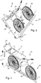
- the carriage 10 illustrated in the drawings comprises a plate 11, a first pair 12 of wheels 13, a second pair 14 of wheels 15, a mast 16, a hook 17 and a blocker 18.
- the plate 11 has a first main face 20 which is facing the ground in the nominal position of the carriage ( Figures 1 and 2 ) and a second main face 21 located on the opposite side to the first main face 20, that is to say that the second main face 21 looks upwards in the nominal position of the carriage ( Figures 1 and 2 ).
- the plate 11 has side faces 22 to 25 which each extend between an edge of the first main face 20 and an edge of the second main face 21.
- the plate 11 has a rectangular outline.
- a first lateral face 22 and a second lateral face 23 correspond to the short sides of the rectangular contour.
- a third lateral face 24 and a fourth lateral face 25 correspond to the long sides of the rectangular contour.
- the wheels 13 and 15 are fixed to the plate 11 on the side of the first main face 20.
- the mast 16 is fixed to the plate 11 on the side of the second main face 21.
- the mast 16 extends transversely to the plate 11 between a proximal end 26 and a distal end 27.
- the mast 16 defines a trough 28 in the form of gutter.
- the proximal end 26 of the mast 16 is here adjacent to an edge of the second main face 21, in this case the edge located along the first lateral face 22.
- the hollow 28 of the mast 16 is on the opposite side to the edge which runs along the first lateral face 22.
- the hollow 28 is turned towards the end of the carriage 10 which is opposite the end at which the mast 16 is located.
- the hook 17 is fixed to the distal end of the mast 16.
- the hook 17 extends on the side of the hollow 28 of the mast 16.
- the blocker 18 comprises a plastron 30, a frame 31 carrying the plastron 30 and elastic cylinders 32 to urge the frame 31.
- the frame 31 is articulated with respect to the plate 11.
- Each of the elastic cylinders 32 is hinged both with respect to the plate 11 and towards the frame 31.
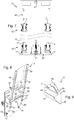
- the plastron 30 is movable along a predetermined path between a position closest to the mast shown on the figure 1 and a position furthest from the mast shown on the Figures 5 and 6 .
- the carriage 10 is configured to maintain between the mast 16 and the blocker 18 a bicycle, such as the bicycle 35 shown on the Figures 2 to 6 or the bicycle 36 shown on the figure 10 .
- the bicycle thus held is suspended from the hook 17 by its front wheel 37.
- the front plate 30 is supported on the saddle 39.
- the front wheel 37 and the rear wheel 38 are engaged in the recess 28 of the mast 16.
- the carriage 10 thus holds the bicycle such as 35 or 36 when it is in nominal position ( Figures 1, 2 , 10 and 11 ) where it is able to transport the bicycle from one place to another, with in particular the wheels 13 and 15 which are in contact with the ground.
- the carriage 10 is configured to admit, in addition to the nominal position, a loading / unloading position ( Figures 4 to 7 ) where placing the bicycle in the cart and the removing the bike from the cart are easier than in the nominal position.
- the carriage 10 is tilted by a quarter of a turn.
- the plastron 30 or the frame 31 is grasped to move the plastron 30 away from the bicycle until the plastron 30 is placed in the the unobstructed position, that is to say the position where it is farthest from the mast 16. It is then in the position illustrated on the figure 5 .
- the resilient cylinders 32 keep the chest 30 in the open position.
- the procedure is similar but in the opposite direction, that is to say that the bicycle is seized to place its wheels in the hollow 28 of the mast 16 while ensuring the hook 17 engages with the front wheel 37, it acts on the front plate 30 or the frame 31 to bring the front plate 30 of the mast 16, the elastic cylinders 32 then urge the frame 31 so that the front plate 30 comes to bear in saddle 39, and the carriage 10 is tilted back to its nominal position.
- the arrangement of the hook 17 is such that when the bicycle is suspended from the hook 17, the front wheel 37 tends to penetrate into the recess 28 of the mast 16.
- the plastron 30 has a width, that is to say a dimension oriented transversely to the median plane of the trough of the mast, which is greater than the width of a bicycle saddle such as the saddle 39 of the bicycle 35 or the bicycle 36, the width of the saddle being its dimension oriented transversely to the median plane of the bicycle.
- the frame 31 is rigid and the plastron 30 is flexible and elastic material.
- the plastron 30 is made of a sheet of elastomeric material.
- the plastron 30 is wider than the saddle such as 39 and is made of flexible and elastic material, and because the plastron 30 is held in support on the saddle by the elastic cylinders 32, the plastron 30 envelopes narrow the saddle so that the saddle can slide against the chest 30 only if very high efforts are exerted.
- the breastplate 30 prevents or in any case strongly limits the movements of the saddle in a direction transverse to the median plane of the bicycle.
- the bicycle such as 35 or 36 can not oscillate around the hook 17, or in any case can only oscillate very moderately.
- the mast 16 has a length of 1.90 m.
- the mast has a length of between 1.75 m and 1.95 m.
- the front plate has a width of 35 cm.
- the plastron has a width of between 25 cm and 40 cm.
- the plastron In general, given the dimensions that are encountered in practice for common bicycles, it is advantageous for the plastron to be able to bear against a saddle of a bicycle which is at a distance of between 50 cm and 80 cm from the mast; and at a distance from the plateau between 50 cm and 1.20 m.
- the carriage 10 is able to maintain a bicycle without any side element to the bicycle, that is to say situated to the left or right of it, except the mast 16 in the vicinity of the tires and the blocker 18 in the vicinity of the saddle.
- the carriage 10 including when loaded by a bicycle, can be particularly narrow, having for example a width of 40 cm.
- transport can be carried out with the carriage 10 which is coupled to a similar carriage.
- a drawbar 40 is provided which adopts at rest a raised position where it is partially opposite the lateral face 22 of the plate 11.
- nipples 41 are illustrated only on the figure 7 .
- the frame 31 is here formed by two longitudinal members 45 and two crosspieces 46.
- the front plate 30 extends between the two side members 45 in an area located between one end of the side members 45 and the cross members 46.
- the beam 45 is articulated vis-à-vis the plate 11 through a hinge 47 carried by a bracket 48.
- the elastic cylinder 32 is articulated vis-à-vis the plate 11 through a hinge 49 carried by a bracket 50.
- the elastic cylinder 32 is articulated vis-à-vis the spar 45 through a hinge 51.
- the elastic cylinder 32 is a variable length arm tending to take a maximum length.
- the length of the elastic cylinder 32 is minimal.
- the plastron 30 is then in an intermediate position between the position closest to the mast 16 ( figure 1 ) and the furthest position from the mast 16 (open position, Figures 5, 6 and 8 ).
- the blocker 18 is configured so that the elastic cylinder 32 urges the plastron 30 to approach the mast 16 between the nearest position of the mast 16 and the intermediate position; and so that the elastic cylinder 32 urges the plastron 30 to move away from the mast 16 between the intermediate position and the furthest position of the mast 16 (disengaged position).
- the mast 16 has a bottom wall 51 ( figure 1 ) with V-section and lateral wings 52 ( figure 1 ) with straight section.
- Each lateral flange 52 runs along one end of the bottom wall 51.
- the two lateral flanges 52 are substantially parallel to each other.
- the opening of the hollow 28 of the mast 16 is between the lateral wings 52.
- the hollow 28 of the mast 16 first has a portion of constant width, located between the lateral wings 52 and a portion gradually decreasing width, defined by the bottom wall 51.
- the lateral wings 52 have a width which is greater at the proximal end 26 than at the distal end 27 of the mast 16.
- the mast 16 is centered laterally vis-à-vis the plate 11, that is to say that the mast 16 is equidistant from the edge corresponding to the lateral face 24 and the edge corresponding to the lateral face 25.
- the median plane of the hollow 28 is oriented parallel to the long sides of the rectangular contour of the plate 11.
- the plate 11 and the mast 16 are here made of metal material, in this case steel. They are welded to each other.
- the plate 11 is more precisely a massive metal plate, whereby the plate 11 can play the role of ballast lowering the center of gravity of the carriage 10, in favor of its stability.
- the hook 17 has a rigid central core 53 attached to the distal end 27 of the mast 16.
- the core 53 is made of steel and is fixed to the mast 16 by welding.
- the hook 17 has two liners 54 made of rigid but less hard material than that of the core 53.
- the liners 54 are made of plastic.
- the core 53 which is here formed in one piece, comprises a base 55 and a curved tab 56.
- the base 55 has a contour corresponding to that of the edge of the mast 16 at its distal end 27, here being specified that this edge is inclined with respect to the general direction of the mast 16.
- the base 55 is welded to the mast 16 all along its edge.
- the curved paw 56 takes root laterally at the base 55.
- the curved tab 56 From its root, the curved tab 56 has a portion extending in the direction of the mast 16 and a portion extending transversely to the direction of the mast 16.
- the liners 54 sandwich the curved tab 56. They have the same shape as the latter but slightly wider, so that the liners 54 are in excess of the curved tab 56 of the concave side thereof.
- the contact between the front wheel of the bicycle such as 35 or 36 and the hook 17 is provided to be done by the overhang portions of the linings 54.
- the arrangement of the hook 17 makes it possible at the same time to avoid injuring the wheel of the bicycle since the contact is made by a material that is not extremely hard and to benefit from the strength provided by the core 53.
- the hook 17 is arranged so that the contact zone with the wheel of the bicycle is sufficiently far from the mast 16 to allow easy engagement of the hook with the wheel and sufficiently close for there to be a lever arm between the contact point and the hub of the wheel so that there is a torque tending to make the wheel penetrate into the recess 28 of the mast 16 when the bicycle is suspended from the hook 17.
- the part of the hook 17 engaging with the wheel of the bicycle that is to say the curved tab 56, covered with the pads 54, has a particularly small thickness; and that, moreover, because of its inclination, has an orientation similar to that of the spokes of the wheel.
- the hook 17 can thus cooperate in the best conditions with the wheel of the bicycle.
- the hook 17 has a fixed orientation with respect to the mast 16. This has the advantage, compared to an articulated hook, of preventing the hook from being folded against the mast when the carriage 10 is in position. loading / unloading, which would require that it is raised by the user to be engaged in the wheel of the bicycle.
- the carriage 10 is intended to be coupled to a carriage provided with a similar coupling system, for example another carriage 10.
- This coupling system comprises, on one side of the carriage 10, the drawbar 40. On the opposite side to the side where the drawbar 40 is located, the carriage 10 comprises a hook 60.
- the drawbar 40 has a central slot 61 configured to receive a finger of the hook 60.
- the hitch thus formed admits a retracted position in which the two carriages coupled to each other are close together and an extended position in which the two carriages coupled to one another are distant.
- the wheels 13 of the first pair 12 are freely steerable and the wheels 15 of the second pair 14 (located on the same side that the hook 60) are fixed orientation in the direction of movement provided for the carriage 10, that is to say here the orientation of the long sides of the rectangular contour of the plate 11.
- the carriage serves to store a bicycle at a predetermined location.
- the carriage comprises plate tilting guide members such as 11 relative to the ground, configured so that the carriage has a nominal position where the plate such as 11 is lying down and a loading / unloading position where the tray as 11 is standing.
- the tilting guide members with respect to the ground are for example configured so that the plate, and more generally the carriage, pivots about a direction oriented like the lateral face 22 and located near this lateral face, so that the according to this variant switches between the nominal position and the loading / unloading position as the carriage 10 in the manner shown on the Figures 2 to 4 .
- the tilt mounting members are for example implemented by hinges between the plate such as 11 and a floor on the floor.
- This floor is for example associated with cheeks between which the carriage in nominal position.
- a panel can be provided between the cheeks at the rear (side where the blocker 18 is in nominal position) and on the top while at the front (side where is find the mast 16) a panel is associated with the carriage.
- the plate 11 may be arranged differently from a plate having two main faces, for example arranged in the form of a U-shaped beam whose central segment is on the side of the mast such as 16.
Landscapes
- Engineering & Computer Science (AREA)
- Mechanical Engineering (AREA)
- Chemical & Material Sciences (AREA)
- Combustion & Propulsion (AREA)
- Transportation (AREA)
- Handcart (AREA)
- Carriages For Children, Sleds, And Other Hand-Operated Vehicles (AREA)
Claims (15)
- Wagen zum Transportieren eines Fahrrads (35, 36), mit:- einer Platte (11), die eine erste Hauptfläche (20), eine zweite Hauptfläche (21) und Seitenflächen (22-25) aufweist, die sich jede zwischen einem Rand der ersten Hauptfläche (20) und einem Rand der zweiten Hauptfläche (21) erstrecken;- Rädern (13, 15), die an der Platte (11) auf der Seite der ersten Hauptfläche (20) befestigt sind;- einem Mast (16), der an der Platte (11) auf der Seite der zweiten Hauptfläche (21) befestigt ist und sich quer zu der Platte (11) zwischen einem proximalen Ende (26) und einem distalen Ende (27) erstreckt; und- einem Haken (17), der an dem distalen Ende (27) des Mastes (16) befestigt ist;dadurch gekennzeichnet, dass der Mast (16) eine Vertiefung (28) in Form einer Rinne begrenzt; wobei sich der Haken (17) von der Seite der Vertiefung (28) des Mastes (16) erstreckt; und der Wagen (10):- einen Feststeller (18) aufweist mit einer Auflage (30), die entlang einer vorherbestimmten Bahn beweglich ist, in der sich die Auflage an den Mast (16) annähert oder von ihm beabstandet, und mit einem Organ (32), um sich dem Beabstanden der Auflage (30) von dem Mast (16) zu widersetzen; und- ausgestaltet ist, um ein Fahrrad (35, 36) zwischen dem Mast (16) und dem Feststeller (18) zu halten, wobei das Fahrrad (35, 36) an dem Haken (17) über sein Vorderrad (37) aufgehängt ist, wobei das Hinterrad (38) und das Vorderrad (37) des Fahrrads (35, 36) in der Vertiefung (28) des Mastes (16) im Eingriff sind und sich die Auflage (30) auf dem Sattel (39) des Fahrrads (35, 36) abstützt.
- Wagen nach Anspruch 1, dadurch gekennzeichnet, dass das proximale Ende (26) des Mastes (16) an einen Rand der zweiten Hauptfläche (21) der Platte (11) angrenzt, die Vertiefung (28) des Mastes (16) auf der diesem Rand gegenüberliegenden Seite gelegen ist, der Wagen (10) ausgestaltet ist, um eine nominale Position einzunehmen, wo der Mast (16) aufrecht steht, während die Platte (11) liegt, wobei die Räder (13, 15) mit dem Boden in Kontakt sind, und um eine Be-/Entladeposition einzunehmen, wo die Platte (11) aufrecht steht, während der Mast (16) längs des Bodens liegt, wobei die Vertiefung (28) nach oben weist, wobei der Übergang zwischen der nominalen Position und der Be-/Entladeposition durch Schwenken des Wagen (10) erfolgt.
- Wagen nach einem der Ansprüche 1 oder 2, dadurch gekennzeichnet, dass er, um an einem ähnlichen Wagen angekoppelt zu werden, eine Deichsel (40) auf einer ersten Seite und einen Haken (60) auf einer zweiten Seite, die der ersten Seite gegenüberliegt, aufweist.
- Wagen zum Verstauen eines Fahrrads (35, 36) mit:- einer Platte (11);- Führungsorganen zum Schwenken der Platte (11) gegenüber dem Boden, die so ausgestaltet sind, dass der Wagen eine nominale Position einnimmt, wo die Platte liegt, und eine Be-/Entladeposition, wo die Platte aufrecht steht;- einem Mast (16), der sich quer zu der Platte (11) zwischen einem proximalen Ende (26) und einem distalen Ende (27) erstreckt; und- einem Haken (17), der an dem distalen Ende (27) des Mastes (16) befestigt ist;dadurch gekennzeichnet, dass der Mast (16) eine Vertiefung (28) in Form einer Rinne begrenzt; wobei sich der Haken (17) von der Seite der Vertiefung (28) des Mastes (16) erstreckt; und der Wagen (10):- einen Feststeller (18) aufweist mit einer Auflage (30), die entlang einer vorherbestimmten Bahn beweglich ist, in der sich die Auflage an den Mast (16) annähert oder von ihm beabstandet, und mit einem Organ (32), um sich dem Beabstanden der Auflage (30) von dem Mast (16) zu widersetzen; und- ausgestaltet ist, um ein Fahrrad (35, 36) zwischen dem Mast (16) und dem Feststeller (18) zu halten, wobei in nominaler Position das Fahrrad (35, 36) an dem Haken (17) über sein Vorderrad (37) aufgehängt ist, wobei das Hinterrad (38) und das Vorderrad (37) des Fahrrads (35, 36) in der Vertiefung (28) des Mastes (16) im Eingriff sind und sich die Auflage (30) auf dem Sattel (39) des Fahrrads (35, 36) abstützt.
- Wagen nach einem der Ansprüche 1 bis 4, dadurch gekennzeichnet, dass der Panzer (30) eine Breite aufweist, die größer ist als die Breite eines Sattels (39) des Fahrrads (35, 36).
- Wagen nach einem der Ansprüche 1 bis 5, dadurch gekennzeichnet, dass die Auflage (30) aus einem flexiblen und elastischen Material ist.
- Wagen nach einem der Ansprüche 1 bis 6, dadurch gekennzeichnet, dass der Feststeller (18) so ausgestaltet ist, dass die Auflage (30) eine freigegebene Position einnimmt, in der sie von dem Mast (16) beabstandet ist, und ein Organ (32) aufweist, um die Auflage (30) in der freigegebenen Position verbleiben zu lassen.
- Wagen nach einem der Ansprüche 1 bis 7, dadurch gekennzeichnet, dass das Organ, um sich dem Beabstanden der Auflage (30) von dem Mast (16) zu widersetzen, ein elastisches Organ (32) ist, das die Auflage (30) zur Annäherung an den Mast (16) beaufschlagt.
- Wagen nach Anspruch 8, dadurch gekennzeichnet, dass der Feststeller (18) so ausgestaltet ist, dass das elastische Organ (32) die Auflage (30) zur Annäherung an den Mast (16) zwischen einer dem Mast (16) am nächsten gelegenen Position und einer Zwischenposition beaufschlagt; und dass das elastische Organ (32) die Auflage (30) zur Beabstandung von dem Mast (16) zwischen der Zwischenposition und einer von dem Mast (16) am weitesten entfernten Position beaufschlagt.
- Wagen nach Anspruch 9, dadurch gekennzeichnet, dass das elastische Organ ein Arm (32) variabler Länge ist, der dazu tendiert, eine maximale Länge einzunehmen; der Feststeller (18) einen Rahmen (31), der die Auflage (30) trägt, ein Gelenk zwischen dem Rahmen (31) und der Platte (11), ein Gelenk zwischen einem Ende des Armes (32) variabler Länge und der Platte (11) und ein Gelenk zwischen dem anderen Ende des Armes (32) variabler Länge und dem Rahmen (31) aufweist; und in der Zwischenposition der Auflage (30) diese drei Gelenke fluchten.
- Wagen nach einem der Ansprüche 1 bis 10, dadurch gekennzeichnet, dass der Feststeller (18) einen Rahmen (31) aufweist, der die Auflage (30) trägt, wobei der Rahmen (31) zwei Längsträger (45) aufweist, die jeder an der Platte (11) angelenkt sind.
- Wagen nach einem der Ansprüche 1 bis 11, dadurch gekennzeichnet, dass der Mast (16) eine Bodenwand (51) mit V-förmigem Querschnitt und seitliche Flügel (52) mit geradem Querschnitt aufweist, wobei jeder seitliche Flügel (52) an einem der Enden der Bodenwand (51) entlang geführt ist.
- Wagen nach einem der Ansprüche 1 bis 12, dadurch gekennzeichnet, dass der Haken (17) einen mittigen Kern (53) und Verstärkungen (54), die eine gekrümmte Klaue (56), die den mittigen Kern (53) aufweist, sandwichartig fassen, aufweist, wobei die Verstärkungen (54) über die gekrümmte Klaue (56) auf deren konkaver Seite überstehen.
- Wagen nach einem der Ansprüche 1 bis 13, dadurch gekennzeichnet, dass der Haken (17) gegenüber dem Mast (16) geneigt ist und eine feste Ausrichtung hat.
- Wagen nach einem der Ansprüche 1 bis 14, dadurch gekennzeichnet, dass die Platte (11) von einer massiven Metallplatte gebildet ist.
Applications Claiming Priority (2)
| Application Number | Priority Date | Filing Date | Title |
|---|---|---|---|
| FR1550447A FR3031716B1 (fr) | 2015-01-20 | 2015-01-20 | Chariot pour transporter une bicyclette |
| PCT/FR2016/050108 WO2016116701A1 (fr) | 2015-01-20 | 2016-01-20 | Chariot pour transporter ou ranger une bicyclette |
Publications (2)
| Publication Number | Publication Date |
|---|---|
| EP3247610A1 EP3247610A1 (de) | 2017-11-29 |
| EP3247610B1 true EP3247610B1 (de) | 2019-03-13 |
Family
ID=52824436
Family Applications (1)
| Application Number | Title | Priority Date | Filing Date |
|---|---|---|---|
| EP16705567.2A Active EP3247610B1 (de) | 2015-01-20 | 2016-01-20 | Wagen zum transportieren oder parken eines fahrrades |
Country Status (6)
| Country | Link |
|---|---|
| EP (1) | EP3247610B1 (de) |
| CN (1) | CN107107935B (de) |
| DK (1) | DK3247610T3 (de) |
| ES (1) | ES2724009T3 (de) |
| FR (1) | FR3031716B1 (de) |
| WO (1) | WO2016116701A1 (de) |
Families Citing this family (6)
| Publication number | Priority date | Publication date | Assignee | Title |
|---|---|---|---|---|
| FR3031716B1 (fr) * | 2015-01-20 | 2017-02-17 | Labadis | Chariot pour transporter une bicyclette |
| DE202016005478U1 (de) * | 2016-08-29 | 2016-10-27 | Messingschlager GmbH & Co. KG | Fahrradständer |
| CN107738607A (zh) * | 2017-10-31 | 2018-02-27 | 天津市驰恩特车业有限公司 | 一种自行车运输固定装置 |
| CN108569321B (zh) * | 2018-05-22 | 2020-08-11 | 台州市路桥高精模具厂 | 一种共享单车简易拖动车 |
| CN108945175B (zh) * | 2018-06-20 | 2024-01-12 | 湖北三峡职业技术学院 | 墙面自行车架及使用方法 |
| DK3623546T3 (da) * | 2018-09-11 | 2021-02-15 | Smart City Concepts Gmbh | Transportør til tohjulede køretøjer |
Family Cites Families (8)
| Publication number | Priority date | Publication date | Assignee | Title |
|---|---|---|---|---|
| FR2800676B1 (fr) | 1999-11-09 | 2002-01-18 | Valeo Thermique Moteur Sa | Dispositif d'attelage pour chariot de manutention |
| US8528749B2 (en) * | 2011-01-07 | 2013-09-10 | David Kerman | Free-standing storage rack for one or more bicycles |
| GB2513278A (en) * | 2012-02-17 | 2014-10-22 | Adrian Min Yan Lee | Remote storage system |
| ES1077123Y (es) * | 2012-05-04 | 2012-09-07 | Serveis Maquinaria Banyolina S L | Soporte mural para bicicletas |
| AT513790B1 (de) * | 2012-12-27 | 2015-11-15 | Gerhard Bauer S E Bike Gmbh | Vertikal-Fahrradhaltevorrichtung |
| ES1078839Y (es) * | 2013-01-29 | 2013-06-12 | Ferrer Francisco E Franch | Soporte movil para bicicletas |
| FR3031716B1 (fr) * | 2015-01-20 | 2017-02-17 | Labadis | Chariot pour transporter une bicyclette |
| CN205615389U (zh) * | 2016-03-29 | 2016-10-05 | 深圳市凯卓立液压设备有限公司 | 一种双层自行车转运箱结构 |
-
2015
- 2015-01-20 FR FR1550447A patent/FR3031716B1/fr not_active Expired - Fee Related
-
2016
- 2016-01-20 ES ES16705567T patent/ES2724009T3/es active Active
- 2016-01-20 WO PCT/FR2016/050108 patent/WO2016116701A1/fr not_active Ceased
- 2016-01-20 DK DK16705567.2T patent/DK3247610T3/da active
- 2016-01-20 CN CN201680006156.8A patent/CN107107935B/zh active Active
- 2016-01-20 EP EP16705567.2A patent/EP3247610B1/de active Active
Non-Patent Citations (1)
| Title |
|---|
| None * |
Also Published As
| Publication number | Publication date |
|---|---|
| WO2016116701A1 (fr) | 2016-07-28 |
| DK3247610T3 (da) | 2019-06-17 |
| FR3031716A1 (fr) | 2016-07-22 |
| FR3031716B1 (fr) | 2017-02-17 |
| ES2724009T3 (es) | 2019-09-05 |
| CN107107935B (zh) | 2019-09-27 |
| EP3247610A1 (de) | 2017-11-29 |
| CN107107935A (zh) | 2017-08-29 |
Similar Documents
| Publication | Publication Date | Title |
|---|---|---|
| WO2016116701A1 (fr) | Chariot pour transporter ou ranger une bicyclette | |
| EP0029384B1 (de) | Gabelstapler mit gleichzeitiger Steuerung von verstellbar angetriebenen Roll- und Greifflächen | |
| FR2774639A1 (fr) | Dispositif, appareil et procede pour permettre a un vehicule de prendre ou de poser au sol une charge presentant un moyen de prehension a l'avant | |
| FR2704189A1 (fr) | Appareil pour permettre à un véhicule de prendre ou de poser au sol une charge telle qu'une benne, et éventuellement de la vider. | |
| EP3791846B1 (de) | Vorrichtung zum sichern des motorisierten be- und/oder entladens eines wagens, der eine krankentrage trägt, entsprechende aufnahmehalterung und entsprechender krankenwagen | |
| EP0905083B1 (de) | Wagen mit Hubmast, geeignet zur Montage an das Ende eines Transportfahrzeugs | |
| EP0374019A1 (de) | System zum Transportieren und Ablegen von mindestens einem Brückenteil von einem Fahrzeug, wie ein Pionierpanzer | |
| EP3377397B1 (de) | Fahrzeug zum transportieren einer last | |
| FR2822422A1 (fr) | Appareil de manutention d'une charge, vehicule le comportant et procede pour soulever une charge avec un tel vehicule | |
| EP1243464A1 (de) | Ladevorrichtung und ein mit solch einer Ladevorrichtung ausgerüstetes Fahrzeug | |
| FR2876668A1 (fr) | Conteneur du type a embase en forme de palette et a deux surfaces support | |
| EP3177467B1 (de) | Reihe von wagen mit schleppkonfiguration | |
| EP2505429B1 (de) | Verfahren zur Regulierung des Achsabstands einer rollenden Einheit, die mindestens zwei Fördervorrichtungen für Container umfasst | |
| EP4551445B1 (de) | Transportwagen mit aufgehängten rollen und mit einem immobilisierungskissen | |
| EP3400622B1 (de) | Stationärer schutzraum zur aufbewahrung von mindestens einer stromspeichereinheit | |
| FR2516022A1 (fr) | Chariot a trois roues | |
| FR3125809A1 (fr) | Dispositif de déplacement-basculement d’une pile d’objets | |
| FR2750088A1 (fr) | Vehicule equipe d'un dispositif de manutention a bras de levage hydraulique | |
| CH484827A (fr) | Chariot auxiliaire permettant d'utiliser un chariot élévateur à fourche frontale comme chariot élévateur à fourche latérale | |
| FR3100174A1 (fr) | système de déplacement d’une benne amovible | |
| EP2990263B1 (de) | Strassentransportfahrzeug mit einer haltestruktur zum beladen mit automatischem ein- und ausklinksystem | |
| EP4477518A1 (de) | Verfahren zum umrüsten eines fahrradanhängers, eines fahrradanhängermodus in einen wagenmodus und fahrradanhänger mit verwendung davon | |
| FR2989574A1 (fr) | Dispositif d'aide a l'embarquement et au debarquement d'un brancard dans un vehicule de transport, et vehicule de transport equipe dudit dispositif | |
| FR2762299A1 (fr) | Casier pour le stockage, le transport et la distribution de bouteilles de gaz | |
| FR3037308A1 (fr) | Remorque destinee a etre attelee a un vehicule tracteur et ensemble attele comprenant une telle remorque |
Legal Events
| Date | Code | Title | Description |
|---|---|---|---|
| STAA | Information on the status of an ep patent application or granted ep patent |
Free format text: STATUS: THE INTERNATIONAL PUBLICATION HAS BEEN MADE |
|
| PUAI | Public reference made under article 153(3) epc to a published international application that has entered the european phase |
Free format text: ORIGINAL CODE: 0009012 |
|
| STAA | Information on the status of an ep patent application or granted ep patent |
Free format text: STATUS: REQUEST FOR EXAMINATION WAS MADE |
|
| 17P | Request for examination filed |
Effective date: 20170721 |
|
| AK | Designated contracting states |
Kind code of ref document: A1 Designated state(s): AL AT BE BG CH CY CZ DE DK EE ES FI FR GB GR HR HU IE IS IT LI LT LU LV MC MK MT NL NO PL PT RO RS SE SI SK SM TR |
|
| AX | Request for extension of the european patent |
Extension state: BA ME |
|
| DAV | Request for validation of the european patent (deleted) | ||
| DAX | Request for extension of the european patent (deleted) | ||
| GRAP | Despatch of communication of intention to grant a patent |
Free format text: ORIGINAL CODE: EPIDOSNIGR1 |
|
| STAA | Information on the status of an ep patent application or granted ep patent |
Free format text: STATUS: GRANT OF PATENT IS INTENDED |
|
| INTG | Intention to grant announced |
Effective date: 20180703 |
|
| GRAS | Grant fee paid |
Free format text: ORIGINAL CODE: EPIDOSNIGR3 |
|
| GRAJ | Information related to disapproval of communication of intention to grant by the applicant or resumption of examination proceedings by the epo deleted |
Free format text: ORIGINAL CODE: EPIDOSDIGR1 |
|
| GRAL | Information related to payment of fee for publishing/printing deleted |
Free format text: ORIGINAL CODE: EPIDOSDIGR3 |
|
| STAA | Information on the status of an ep patent application or granted ep patent |
Free format text: STATUS: REQUEST FOR EXAMINATION WAS MADE |
|
| RAP1 | Party data changed (applicant data changed or rights of an application transferred) |
Owner name: LABADIS WORKS |
|
| GRAP | Despatch of communication of intention to grant a patent |
Free format text: ORIGINAL CODE: EPIDOSNIGR1 |
|
| STAA | Information on the status of an ep patent application or granted ep patent |
Free format text: STATUS: GRANT OF PATENT IS INTENDED |
|
| RAP1 | Party data changed (applicant data changed or rights of an application transferred) |
Owner name: LABADIS SAS |
|
| INTC | Intention to grant announced (deleted) | ||
| INTG | Intention to grant announced |
Effective date: 20181126 |
|
| GRAA | (expected) grant |
Free format text: ORIGINAL CODE: 0009210 |
|
| STAA | Information on the status of an ep patent application or granted ep patent |
Free format text: STATUS: THE PATENT HAS BEEN GRANTED |
|
| AK | Designated contracting states |
Kind code of ref document: B1 Designated state(s): AL AT BE BG CH CY CZ DE DK EE ES FI FR GB GR HR HU IE IS IT LI LT LU LV MC MK MT NL NO PL PT RO RS SE SI SK SM TR |
|
| REG | Reference to a national code |
Ref country code: GB Ref legal event code: FG4D Free format text: NOT ENGLISH |
|
| REG | Reference to a national code |
Ref country code: CH Ref legal event code: EP Ref country code: AT Ref legal event code: REF Ref document number: 1107315 Country of ref document: AT Kind code of ref document: T Effective date: 20190315 |
|
| REG | Reference to a national code |
Ref country code: DE Ref legal event code: R096 Ref document number: 602016011031 Country of ref document: DE |
|
| REG | Reference to a national code |
Ref country code: IE Ref legal event code: FG4D Free format text: LANGUAGE OF EP DOCUMENT: FRENCH |
|
| REG | Reference to a national code |
Ref country code: DK Ref legal event code: T3 Effective date: 20190613 |
|
| REG | Reference to a national code |
Ref country code: NL Ref legal event code: FP |
|
| REG | Reference to a national code |
Ref country code: LT Ref legal event code: MG4D |
|
| PG25 | Lapsed in a contracting state [announced via postgrant information from national office to epo] |
Ref country code: LT Free format text: LAPSE BECAUSE OF FAILURE TO SUBMIT A TRANSLATION OF THE DESCRIPTION OR TO PAY THE FEE WITHIN THE PRESCRIBED TIME-LIMIT Effective date: 20190313 Ref country code: SE Free format text: LAPSE BECAUSE OF FAILURE TO SUBMIT A TRANSLATION OF THE DESCRIPTION OR TO PAY THE FEE WITHIN THE PRESCRIBED TIME-LIMIT Effective date: 20190313 Ref country code: NO Free format text: LAPSE BECAUSE OF FAILURE TO SUBMIT A TRANSLATION OF THE DESCRIPTION OR TO PAY THE FEE WITHIN THE PRESCRIBED TIME-LIMIT Effective date: 20190613 Ref country code: FI Free format text: LAPSE BECAUSE OF FAILURE TO SUBMIT A TRANSLATION OF THE DESCRIPTION OR TO PAY THE FEE WITHIN THE PRESCRIBED TIME-LIMIT Effective date: 20190313 |
|
| PG25 | Lapsed in a contracting state [announced via postgrant information from national office to epo] |
Ref country code: HR Free format text: LAPSE BECAUSE OF FAILURE TO SUBMIT A TRANSLATION OF THE DESCRIPTION OR TO PAY THE FEE WITHIN THE PRESCRIBED TIME-LIMIT Effective date: 20190313 Ref country code: GR Free format text: LAPSE BECAUSE OF FAILURE TO SUBMIT A TRANSLATION OF THE DESCRIPTION OR TO PAY THE FEE WITHIN THE PRESCRIBED TIME-LIMIT Effective date: 20190614 Ref country code: LV Free format text: LAPSE BECAUSE OF FAILURE TO SUBMIT A TRANSLATION OF THE DESCRIPTION OR TO PAY THE FEE WITHIN THE PRESCRIBED TIME-LIMIT Effective date: 20190313 Ref country code: BG Free format text: LAPSE BECAUSE OF FAILURE TO SUBMIT A TRANSLATION OF THE DESCRIPTION OR TO PAY THE FEE WITHIN THE PRESCRIBED TIME-LIMIT Effective date: 20190613 Ref country code: RS Free format text: LAPSE BECAUSE OF FAILURE TO SUBMIT A TRANSLATION OF THE DESCRIPTION OR TO PAY THE FEE WITHIN THE PRESCRIBED TIME-LIMIT Effective date: 20190313 |
|
| REG | Reference to a national code |
Ref country code: ES Ref legal event code: FG2A Ref document number: 2724009 Country of ref document: ES Kind code of ref document: T3 Effective date: 20190905 |
|
| REG | Reference to a national code |
Ref country code: AT Ref legal event code: MK05 Ref document number: 1107315 Country of ref document: AT Kind code of ref document: T Effective date: 20190313 |
|
| PG25 | Lapsed in a contracting state [announced via postgrant information from national office to epo] |
Ref country code: SK Free format text: LAPSE BECAUSE OF FAILURE TO SUBMIT A TRANSLATION OF THE DESCRIPTION OR TO PAY THE FEE WITHIN THE PRESCRIBED TIME-LIMIT Effective date: 20190313 Ref country code: PT Free format text: LAPSE BECAUSE OF FAILURE TO SUBMIT A TRANSLATION OF THE DESCRIPTION OR TO PAY THE FEE WITHIN THE PRESCRIBED TIME-LIMIT Effective date: 20190713 Ref country code: AL Free format text: LAPSE BECAUSE OF FAILURE TO SUBMIT A TRANSLATION OF THE DESCRIPTION OR TO PAY THE FEE WITHIN THE PRESCRIBED TIME-LIMIT Effective date: 20190313 Ref country code: CZ Free format text: LAPSE BECAUSE OF FAILURE TO SUBMIT A TRANSLATION OF THE DESCRIPTION OR TO PAY THE FEE WITHIN THE PRESCRIBED TIME-LIMIT Effective date: 20190313 Ref country code: RO Free format text: LAPSE BECAUSE OF FAILURE TO SUBMIT A TRANSLATION OF THE DESCRIPTION OR TO PAY THE FEE WITHIN THE PRESCRIBED TIME-LIMIT Effective date: 20190313 Ref country code: EE Free format text: LAPSE BECAUSE OF FAILURE TO SUBMIT A TRANSLATION OF THE DESCRIPTION OR TO PAY THE FEE WITHIN THE PRESCRIBED TIME-LIMIT Effective date: 20190313 |
|
| PG25 | Lapsed in a contracting state [announced via postgrant information from national office to epo] |
Ref country code: SM Free format text: LAPSE BECAUSE OF FAILURE TO SUBMIT A TRANSLATION OF THE DESCRIPTION OR TO PAY THE FEE WITHIN THE PRESCRIBED TIME-LIMIT Effective date: 20190313 Ref country code: PL Free format text: LAPSE BECAUSE OF FAILURE TO SUBMIT A TRANSLATION OF THE DESCRIPTION OR TO PAY THE FEE WITHIN THE PRESCRIBED TIME-LIMIT Effective date: 20190313 |
|
| REG | Reference to a national code |
Ref country code: DE Ref legal event code: R097 Ref document number: 602016011031 Country of ref document: DE |
|
| PG25 | Lapsed in a contracting state [announced via postgrant information from national office to epo] |
Ref country code: IS Free format text: LAPSE BECAUSE OF FAILURE TO SUBMIT A TRANSLATION OF THE DESCRIPTION OR TO PAY THE FEE WITHIN THE PRESCRIBED TIME-LIMIT Effective date: 20190713 Ref country code: AT Free format text: LAPSE BECAUSE OF FAILURE TO SUBMIT A TRANSLATION OF THE DESCRIPTION OR TO PAY THE FEE WITHIN THE PRESCRIBED TIME-LIMIT Effective date: 20190313 |
|
| PLBE | No opposition filed within time limit |
Free format text: ORIGINAL CODE: 0009261 |
|
| STAA | Information on the status of an ep patent application or granted ep patent |
Free format text: STATUS: NO OPPOSITION FILED WITHIN TIME LIMIT |
|
| 26N | No opposition filed |
Effective date: 20191216 |
|
| PG25 | Lapsed in a contracting state [announced via postgrant information from national office to epo] |
Ref country code: SI Free format text: LAPSE BECAUSE OF FAILURE TO SUBMIT A TRANSLATION OF THE DESCRIPTION OR TO PAY THE FEE WITHIN THE PRESCRIBED TIME-LIMIT Effective date: 20190313 |
|
| PG25 | Lapsed in a contracting state [announced via postgrant information from national office to epo] |
Ref country code: TR Free format text: LAPSE BECAUSE OF FAILURE TO SUBMIT A TRANSLATION OF THE DESCRIPTION OR TO PAY THE FEE WITHIN THE PRESCRIBED TIME-LIMIT Effective date: 20190313 |
|
| PG25 | Lapsed in a contracting state [announced via postgrant information from national office to epo] |
Ref country code: MC Free format text: LAPSE BECAUSE OF FAILURE TO SUBMIT A TRANSLATION OF THE DESCRIPTION OR TO PAY THE FEE WITHIN THE PRESCRIBED TIME-LIMIT Effective date: 20190313 |
|
| REG | Reference to a national code |
Ref country code: CH Ref legal event code: PL |
|
| PG25 | Lapsed in a contracting state [announced via postgrant information from national office to epo] |
Ref country code: LU Free format text: LAPSE BECAUSE OF NON-PAYMENT OF DUE FEES Effective date: 20200120 |
|
| PG25 | Lapsed in a contracting state [announced via postgrant information from national office to epo] |
Ref country code: CH Free format text: LAPSE BECAUSE OF NON-PAYMENT OF DUE FEES Effective date: 20200131 Ref country code: LI Free format text: LAPSE BECAUSE OF NON-PAYMENT OF DUE FEES Effective date: 20200131 |
|
| PG25 | Lapsed in a contracting state [announced via postgrant information from national office to epo] |
Ref country code: IE Free format text: LAPSE BECAUSE OF NON-PAYMENT OF DUE FEES Effective date: 20200120 |
|
| PG25 | Lapsed in a contracting state [announced via postgrant information from national office to epo] |
Ref country code: MT Free format text: LAPSE BECAUSE OF FAILURE TO SUBMIT A TRANSLATION OF THE DESCRIPTION OR TO PAY THE FEE WITHIN THE PRESCRIBED TIME-LIMIT Effective date: 20190313 Ref country code: CY Free format text: LAPSE BECAUSE OF FAILURE TO SUBMIT A TRANSLATION OF THE DESCRIPTION OR TO PAY THE FEE WITHIN THE PRESCRIBED TIME-LIMIT Effective date: 20190313 |
|
| PG25 | Lapsed in a contracting state [announced via postgrant information from national office to epo] |
Ref country code: MK Free format text: LAPSE BECAUSE OF FAILURE TO SUBMIT A TRANSLATION OF THE DESCRIPTION OR TO PAY THE FEE WITHIN THE PRESCRIBED TIME-LIMIT Effective date: 20190313 |
|
| P01 | Opt-out of the competence of the unified patent court (upc) registered |
Effective date: 20230512 |
|
| PGFP | Annual fee paid to national office [announced via postgrant information from national office to epo] |
Ref country code: NL Payment date: 20260127 Year of fee payment: 11 |
|
| PGFP | Annual fee paid to national office [announced via postgrant information from national office to epo] |
Ref country code: GB Payment date: 20260127 Year of fee payment: 11 |
|
| PGFP | Annual fee paid to national office [announced via postgrant information from national office to epo] |
Ref country code: ES Payment date: 20260210 Year of fee payment: 11 |
|
| PGFP | Annual fee paid to national office [announced via postgrant information from national office to epo] |
Ref country code: DE Payment date: 20260127 Year of fee payment: 11 Ref country code: DK Payment date: 20260127 Year of fee payment: 11 |
|
| PGFP | Annual fee paid to national office [announced via postgrant information from national office to epo] |
Ref country code: BE Payment date: 20260128 Year of fee payment: 11 Ref country code: IT Payment date: 20260127 Year of fee payment: 11 |
|
| PGFP | Annual fee paid to national office [announced via postgrant information from national office to epo] |
Ref country code: FR Payment date: 20260115 Year of fee payment: 11 |