EP3247659B1 - Procédé et dispositif pour manipuler des couches intermédiaires individuelles - Google Patents
Procédé et dispositif pour manipuler des couches intermédiaires individuelles Download PDFInfo
- Publication number
- EP3247659B1 EP3247659B1 EP16700729.3A EP16700729A EP3247659B1 EP 3247659 B1 EP3247659 B1 EP 3247659B1 EP 16700729 A EP16700729 A EP 16700729A EP 3247659 B1 EP3247659 B1 EP 3247659B1
- Authority
- EP
- European Patent Office
- Prior art keywords
- intermediate layers
- intermediate layer
- layers
- stack
- sensor system
- Prior art date
- Legal status (The legal status is an assumption and is not a legal conclusion. Google has not performed a legal analysis and makes no representation as to the accuracy of the status listed.)
- Active
Links
Images



Classifications
-
- B—PERFORMING OPERATIONS; TRANSPORTING
- B65—CONVEYING; PACKING; STORING; HANDLING THIN OR FILAMENTARY MATERIAL
- B65G—TRANSPORT OR STORAGE DEVICES, e.g. CONVEYORS FOR LOADING OR TIPPING, SHOP CONVEYOR SYSTEMS OR PNEUMATIC TUBE CONVEYORS
- B65G59/00—De-stacking of articles
- B65G59/02—De-stacking from the top of the stack
- B65G59/04—De-stacking from the top of the stack by suction or magnetic devices
-
- B—PERFORMING OPERATIONS; TRANSPORTING
- B65—CONVEYING; PACKING; STORING; HANDLING THIN OR FILAMENTARY MATERIAL
- B65G—TRANSPORT OR STORAGE DEVICES, e.g. CONVEYORS FOR LOADING OR TIPPING, SHOP CONVEYOR SYSTEMS OR PNEUMATIC TUBE CONVEYORS
- B65G47/00—Article or material-handling devices associated with conveyors; Methods employing such devices
- B65G47/22—Devices influencing the relative position or the attitude of articles during transit by conveyors
- B65G47/24—Devices influencing the relative position or the attitude of articles during transit by conveyors orientating the articles
- B65G47/244—Devices influencing the relative position or the attitude of articles during transit by conveyors orientating the articles by turning them about an axis substantially perpendicular to the conveying plane
-
- B—PERFORMING OPERATIONS; TRANSPORTING
- B65—CONVEYING; PACKING; STORING; HANDLING THIN OR FILAMENTARY MATERIAL
- B65H—HANDLING THIN OR FILAMENTARY MATERIAL, e.g. SHEETS, WEBS, CABLES
- B65H1/00—Supports or magazines for piles from which articles are to be separated
- B65H1/28—Supports or magazines for piles from which articles are to be separated compartmented to receive piles side-by-side
-
- B—PERFORMING OPERATIONS; TRANSPORTING
- B65—CONVEYING; PACKING; STORING; HANDLING THIN OR FILAMENTARY MATERIAL
- B65H—HANDLING THIN OR FILAMENTARY MATERIAL, e.g. SHEETS, WEBS, CABLES
- B65H3/00—Separating articles from piles
- B65H3/08—Separating articles from piles using pneumatic force
- B65H3/0808—Suction grippers
- B65H3/0816—Suction grippers separating from the top of pile
-
- B—PERFORMING OPERATIONS; TRANSPORTING
- B65—CONVEYING; PACKING; STORING; HANDLING THIN OR FILAMENTARY MATERIAL
- B65H—HANDLING THIN OR FILAMENTARY MATERIAL, e.g. SHEETS, WEBS, CABLES
- B65H3/00—Separating articles from piles
- B65H3/44—Simultaneously, alternately, or selectively separating articles from two or more piles
- B65H3/443—Simultaneously, alternately, or selectively separating articles from two or more piles simultaneously
-
- B—PERFORMING OPERATIONS; TRANSPORTING
- B65—CONVEYING; PACKING; STORING; HANDLING THIN OR FILAMENTARY MATERIAL
- B65H—HANDLING THIN OR FILAMENTARY MATERIAL, e.g. SHEETS, WEBS, CABLES
- B65H3/00—Separating articles from piles
- B65H3/46—Supplementary devices or measures to assist separation or prevent double feed
- B65H3/56—Elements, e.g. scrapers, fingers, needles, brushes, acting on separated article or on edge of the pile
-
- B—PERFORMING OPERATIONS; TRANSPORTING
- B65—CONVEYING; PACKING; STORING; HANDLING THIN OR FILAMENTARY MATERIAL
- B65H—HANDLING THIN OR FILAMENTARY MATERIAL, e.g. SHEETS, WEBS, CABLES
- B65H7/00—Controlling article feeding, separating, pile-advancing, or associated apparatus, to take account of incorrect feeding, absence of articles, or presence of faulty articles
- B65H7/02—Controlling article feeding, separating, pile-advancing, or associated apparatus, to take account of incorrect feeding, absence of articles, or presence of faulty articles by feelers or detectors
-
- B—PERFORMING OPERATIONS; TRANSPORTING
- B65—CONVEYING; PACKING; STORING; HANDLING THIN OR FILAMENTARY MATERIAL
- B65H—HANDLING THIN OR FILAMENTARY MATERIAL, e.g. SHEETS, WEBS, CABLES
- B65H7/00—Controlling article feeding, separating, pile-advancing, or associated apparatus, to take account of incorrect feeding, absence of articles, or presence of faulty articles
- B65H7/02—Controlling article feeding, separating, pile-advancing, or associated apparatus, to take account of incorrect feeding, absence of articles, or presence of faulty articles by feelers or detectors
- B65H7/14—Controlling article feeding, separating, pile-advancing, or associated apparatus, to take account of incorrect feeding, absence of articles, or presence of faulty articles by feelers or detectors by photoelectric feelers or detectors
-
- B—PERFORMING OPERATIONS; TRANSPORTING
- B65—CONVEYING; PACKING; STORING; HANDLING THIN OR FILAMENTARY MATERIAL
- B65H—HANDLING THIN OR FILAMENTARY MATERIAL, e.g. SHEETS, WEBS, CABLES
- B65H2511/00—Dimensions; Position; Numbers; Identification; Occurrences
- B65H2511/10—Size; Dimensions
-
- B—PERFORMING OPERATIONS; TRANSPORTING
- B65—CONVEYING; PACKING; STORING; HANDLING THIN OR FILAMENTARY MATERIAL
- B65H—HANDLING THIN OR FILAMENTARY MATERIAL, e.g. SHEETS, WEBS, CABLES
- B65H2511/00—Dimensions; Position; Numbers; Identification; Occurrences
- B65H2511/50—Occurence
- B65H2511/51—Presence
- B65H2511/514—Particular portion of element
-
- B—PERFORMING OPERATIONS; TRANSPORTING
- B65—CONVEYING; PACKING; STORING; HANDLING THIN OR FILAMENTARY MATERIAL
- B65H—HANDLING THIN OR FILAMENTARY MATERIAL, e.g. SHEETS, WEBS, CABLES
- B65H2513/00—Dynamic entities; Timing aspects
- B65H2513/40—Movement
- B65H2513/41—Direction of movement
-
- B—PERFORMING OPERATIONS; TRANSPORTING
- B65—CONVEYING; PACKING; STORING; HANDLING THIN OR FILAMENTARY MATERIAL
- B65H—HANDLING THIN OR FILAMENTARY MATERIAL, e.g. SHEETS, WEBS, CABLES
- B65H2513/00—Dynamic entities; Timing aspects
- B65H2513/40—Movement
- B65H2513/42—Route, path
-
- B—PERFORMING OPERATIONS; TRANSPORTING
- B65—CONVEYING; PACKING; STORING; HANDLING THIN OR FILAMENTARY MATERIAL
- B65H—HANDLING THIN OR FILAMENTARY MATERIAL, e.g. SHEETS, WEBS, CABLES
- B65H2553/00—Sensing or detecting means
- B65H2553/40—Sensing or detecting means using optical, e.g. photographic, elements
- B65H2553/41—Photoelectric detectors
- B65H2553/412—Photoelectric detectors in barrier arrangements, i.e. emitter facing a receptor element
-
- B—PERFORMING OPERATIONS; TRANSPORTING
- B65—CONVEYING; PACKING; STORING; HANDLING THIN OR FILAMENTARY MATERIAL
- B65H—HANDLING THIN OR FILAMENTARY MATERIAL, e.g. SHEETS, WEBS, CABLES
- B65H2557/00—Means for control not provided for in groups B65H2551/00 - B65H2555/00
- B65H2557/50—Use of particular electromagnetic waves, e.g. light, radiowaves or microwaves
- B65H2557/51—Laser
-
- B—PERFORMING OPERATIONS; TRANSPORTING
- B65—CONVEYING; PACKING; STORING; HANDLING THIN OR FILAMENTARY MATERIAL
- B65H—HANDLING THIN OR FILAMENTARY MATERIAL, e.g. SHEETS, WEBS, CABLES
- B65H2701/00—Handled material; Storage means
- B65H2701/10—Handled articles or webs
- B65H2701/17—Nature of material
- B65H2701/176—Cardboard
Definitions
- the present invention relates to a method and a device for handling individual intermediate layers.
- the respective pallet preferably several layers of articles on the respective pallet are arranged one above the other to be able to place a large number of articles on the respective pallet can.
- the articles may be formed for example by containers with several beverage containers.
- Such articles often have a complex geometry, so that multi-layer stacking is not always possible without attendant problems with the stability of the entire pallet assembly. In particular, during transport of the pallet, it is necessary to be able to ensure a certain stability for the pallet assembly in order to exclude tilting of the respective articles with certainty.
- intermediate articles In order to increase the stability of the pallet assembly or to be able to ensure sufficient stability for the pallet assembly, it is known from the prior art, so-called for intermediate articles to provide intermediate layers. Such intermediate layers may extend at least approximately over the entire pallet width, so that all articles stand up on such an intermediate layer.
- Known intermediate layers are formed for example from paper, cardboard, cardboard, corrugated cardboard or similar materials. Due to their rigidity, a stable contact surface for stacked article layers is provided in each case by means of the intermediate layers. It may also be that for a plane of the pallet a plurality of intermediate layers are provided or that a plane of the pallet is formed by a plurality of intermediate layers on which the articles stand up.
- interlayer stacks comprising a plurality of such interlayers are known.
- such a device discloses the DE 10 2004 031 301 A1 .
- a stack of intermediate layers is provided and received via a gripper with suction cups. Subsequently, the intermediate layer is lifted by the gripper and deposited on the respective pallet. After settling the gripper is moved back to pick up the next liner.
- the DE 40 28 981 A1 also discloses a method according to the preamble of claim 1 and a device for positioning workpieces according to the preamble of claim 11, which are formed by textile blanks. About a arranged on a bridge gripper or by hand, a respective textile blank is placed on a table. There, a camera recognizes the contour of each stored on the table textile blank.
- An object of the present invention can therefore be seen to provide a method and an apparatus which contribute to the exact positioning of a plurality of intermediate layers on associated pallets.
- the device should also have a simple structure. Next, the process should be easy to implement. In addition, the method and the device should be characterized by a high throughput.
- the invention relates to a method for handling individual intermediate layers.
- a first step of the method according to the invention which may usefully precede the following steps in time, at least two separate intermediate layer stacks each separate a single intermediate layer arranged on top of the respective intermediate layer stack.
- two intermediate layer stacks may be provided which are positioned adjacent to one another and from which an intermediate layer is separated at least approximately at the same time.
- a respective intermediate layer arranged on top of a first stack of intermediate layers and a respective intermediate layer arranged on top of a second stack of intermediate layers can jointly provide a level or floor space for articles when palletizing.
- the intermediate layers of the at least two intermediate layer stacks can thus be designed as so-called half layers.
- the individual intermediate layers can be detected, for example, by at least two independently movable suction and / or gripping device and be deducted in time by a method of suction and / or gripping device from the stack of intermediate layers.
- the suction and / or gripping devices can first cause lifting of their respective intermediate layer from the stack of layers prior to removal of the intermediate layer.
- the suction and / or gripping devices can in this case first lift a front edge of their respective intermediate layer, while a rear edge of their respective intermediate layer remains in contact with the respective intermediate layer stack and loses its contact with the intermediate layer stack only upon removal of the respective intermediate layer from the respective intermediate layer stack.
- the respective intermediate layer can be bent or concave deformed at least in certain areas. As a result, the liner effectively from the respective Separator stack separately, without further intermediate layers adhere to the separated from the respective stack of layers intermediate layer.
- the individual intermediate layers separated from the at least two separate intermediate layer stacks are moved into a detection region of a sensor system, wherein each of the separated intermediate layers enters a detection region of its own sensor system.
- the detection areas may not overlap here.
- Each of the intermediate layer stacks or the intermediate layers of each stack can thus be assigned its own sensor system.
- the respective own sensor detects a running in the direction of movement of the respective intermediate outer edge by means of preferably optical detection.
- a first sensor system can detect the outer edge of a first intermediate layer of a first intermediate layer stack, wherein a second sensor system detects the outer edge of a second intermediate layer of a second intermediate layer stack.
- the intermediate layers of the at least two separate intermediate layer stacks each have opposite square broad side surfaces, with two opposite outer edges as well as the front edge and the rear edge forming the circumferential course.
- the respective sensor system comprises a camera system in order to detect the outer edge running in the direction of movement of the respective intermediate layer.
- the outer edge running in the direction of movement of the respective intermediate layer is optically detected by means of a light barrier or by means of a laser.
- the invention is not limited to such embodiments, so that there are further possibilities for the person skilled in the art to optically recognize the outer edge running in the direction of movement of the respective intermediate layer.
- the respective intermediate layer is not yet completely deducted from the respective stack of layers or still partially rests on the stack of intermediate layers and in this case passes into the detection range of the respective sensor. It may also be that the respective liner initially is completely deducted from the respective stack of interleaves or no longer has contact with the interleave stack and is subsequently moved into the detection range of the respective sensor. The removal and the movement into the detection range of the respective sensor can continue via a gripping and / or suction device which moves and holds the respective intermediate layer during the preferably optical detection of its outer edge. The intermediate layers are accordingly moved according to the invention with preferably optical detection of their respective outer edge or do not stand still.
- the separated individual layers in time travel to a respective destination, taking into account the respective preferably optical detection, so that the intermediate layers reach their respective destination with a predetermined position.
- the respective intermediate layers can approach their respective destination with a specific direction of movement and taking into account the respective preferably optical detection after each preferably optical detection.
- the intermediate layers can continue to be transferred from the at least two suction and / or gripping devices to the respective destination or be moved via the at least two suction and / or gripping devices from the detection range of the respective sensors in the direction of the destination.
- the intermediate layers if necessary via the at least two suction and / or gripping devices, starting with the removal and until the transfer to the destination, can be moved continuously and without interruption.
- the position of the intermediate layers at the respective destination exactly corresponds to a desired desired position or at least approximately coincides with a predetermined desired position.
- the transfer of intermediate layers to the respective pallet can take place here with high precision, so that stable pallets can be assembled with the aid of the method according to the invention or the device according to the invention. Also problems with palletizing, which arise for example due to an inaccurate position of the intermediate layers on the pallet, can be avoided with the method according to the invention and the device according to the invention.
- a pallet is arranged at the destination, so that the intermediate layers deposited directly on the pallet at the destination become.
- the depositing of the intermediate layers at the respective destination or on the pallet may possibly be effected by the at least two suction and / or gripping devices.
- the intermediate layers are received at the respective destination or transferred by the suction and / or gripping devices to further means of transport.
- the intermediate layers are received at the destination by one or more movable clamping elements and pulled in the direction of a transfer point.
- the suction and / or gripping devices can solve their connection to the intermediate layers after receipt by the one or more movable clamping elements and then be moved back in the direction of the respective intermediate layer stack.
- the one or more movable clamping elements are moved horizontally and pull the liners in the direction of a transfer point.
- the transfer station can provide a horizontal support for the intermediate layers.
- the one or more moveable clamping elements can release their connection to the respective intermediate layer.
- the intermediate layers or half layers can for example be picked up by a handling device and deposited on the assigned pallet.
- the clamping elements can then be moved back in the direction of the respective destination and there take further intermediate layers of the at least two suction and / or gripping device.
- embodiments have proved successful in practice in which the one or more clamping elements are moved linearly.
- handling devices are conceivable, which detect the intermediate layers mechanically and, for example, medium gripping fingers and subsequently deposit them on the pallet.
- embodiments have proved useful in which, prior to separation of individual intermediate layers, their leading edge adjoining the outer edge and their rear edge adjoining the outer edge are aligned. Such embodiments also help to allow accurate positioning of liners on pallets.
- the alignment can be carried out in such a way that several intermediate layers positioned on top of the respective intermediate layer stack are thereby oriented substantially flush with one another or lie flush on one another. Thus, after aligning an actual position of the leading edge with a desired position at least approximately match.
- embodiments have proven in which for aligning at least two deliverable stops against the front and rear edges of several intermediate layers of the at least two layers of inlays are each guided, so that in this way the plurality of intermediate layers of the at least two layers of layers are aligned flush with each other.
- the at least two deliverable stops can be oriented parallel to one another during their delivery movement and during their contact with the intermediate layers.
- a stop provided for flush alignment of intermediate layers and a stop provided for flush alignment of intermediate layers align both several intermediate layers of a first intermediate layer stack and several intermediate layers of a second intermediate layer stack flush with each other.
- the separated intermediate layer are moved into the detection area of the respective sensor system in a time-synchronized manner with a first directional component pointing in the direction of the destination and with a second directional component oriented perpendicular to the first directional component.
- the intermediate layers can therefore be deducted obliquely and in the direction away from their respective layer stack of the respective stack of layers.
- the detection range of the respective sensor can therefore be offset in the withdrawal direction of the respective intermediate layer and positioned laterally of the respective intermediate layer stack.
- the outer edges extending in the direction of movement of the separated intermediate layers can be optically detected by means of a light barrier.
- the light barriers may each comprise a source or a transmitter which transmits or emits radiation in the direction of a receiver.
- the respective source can be designed as a laser.
- the light barriers for optical detection of the running in the direction of movement of the intermediate layers outer edges emit a beam load.
- the intermediate layers can enter via their outer edges in the respective radiation and thereby interrupt the radiation at least partially.
- the respective receiver can then inform an associated with the respective sensor control device via an actual position of the outer edges, which control device specifies the further direction of movement of the intermediate layers or possibly the at least two suction and / or gripping devices in the direction of the respective destination, so that the intermediate layers reach their respective destination with a predetermined position.
- touch sensors can be used to detect the outer edge of the intermediate layer.
- capacitive sensors and / or ultrasound sensors are used to detect the outer edge of the intermediate layer.
- the respective predetermined position can be selected for intermediate layers such that the intermediate layers have a defined distance or gap at the predetermined destination.
- the intermediate layers or half layers can then be transferred to a pallet.
- the defined distance or the gap between the at least two intermediate layers may continue to be formed after transfer of the intermediate layers to the associated pallet.
- no gap or no gap is formed between the intermediate layers at the destination, so intermediate layers directly adjoin one another at the destination, with their adjacent outer edges possibly in surface contact with one another.
- individual intermediate layers are separated from the at least two separate intermediate layer stacks, at least approximately time-synchronously. It is also conceivable that the intermediate layers separated from the at least two separate intermediate layer stacks enter at least approximately time-synchronously into the detection range of the own sensor system and / or that the separated individual intermediate layers approach their respective destination at least approximately time-synchronously.
- the present invention also relates to a device for handling individual intermediate layers of an interlayer stack.
- Features which have been previously described to conceivable embodiments of the method can also be provided in conceivable embodiments of the device according to the invention. Further, features which are described below to conceivable embodiments of the device according to the invention, be provided in conceivable embodiments of the method according to the invention.
- the device according to the invention comprises at least two independently movable suction and / or gripping devices for respectively separating a single intermediate layer from an intermediate layer stack and transferring the separated intermediate layer to a destination.
- Each of the at least two independently movable suction and / or gripping devices is designed for separating a single intermediate layer from its own interlayer stack.
- the at least two suction and / or gripping device can therefore be moved back and forth from the respective intermediate layer stack or from a respective provisioning station for the interlayer stack and the destination.
- the at least two suction and / or gripping devices can each comprise one or more suction heads, by means of which the respective intermediate layer can be temporarily fixed to the respective suction and / or gripping device.
- the device according to the invention also comprises a separate sensor system for each of the at least two suction and / or gripping devices, via which a respective outer edge extending in the direction of movement of the separated intermediate layers can be detected by means of preferably optical detection.
- a control device is provided, which is in communication with the at least two suction and / or gripping devices and their respective sensors, wherein the movement directions of the at least two suction and / or gripping devices independently of one another and taking into account the preferably optical detections of the control device can be specified that the pads reach their destination each with a predetermined position.
- the intermediate layers can reach their respective destination very precisely with a specific desired position. This is also possible if an intermediate layer located at the top of the stack of liners projects laterally from the stack of liners.
- the own sensor system of at least one of the at least two suction and / or gripping devices comprises one or more light barriers.
- the one or more light barriers of the respective sensor system may comprise at least one laser transmitter.
- the device comprises at least two stops, which can be brought into contact by means of an initiated by the control device feed movement for flush alignment with a plurality of top layers arranged on the intermediate layer stacks. It is also conceivable that the control device can control a movement of the at least two suction and / or gripping devices in such a way that the intermediate layers reach their respective destination at least approximately synchronously in time.
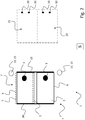
- FIG. 1 shows a schematic view of an embodiment of a device 1 according to the invention and illustrates a first step of an embodiment of a method according to the invention.
- the device 1 is provided for handling with intermediate layers 5.
- the intermediate layers 5 are presently designed as half layers and placed on two adjacent intermediate layer stacks 7.
- the intermediate layers 5 of the lower layer stack 7 are aligned flush with each other.
- the uppermost on the further intermediate layer stack 7 arranged intermediate layer 5, which in FIG. 1 is shown in phantom lines, has no flush alignment with the other intermediate layers 5 of the intermediate layer stack 7, on which it rests.
- the device 1 additionally comprises two movable suction and / or gripping devices 3, wherein each suction and / or gripping device 3 is assigned its own interlayer stack 7, from which the respective suction and / or gripping device 3 separates intermediate layers 5.
- the suction and / or gripping devices 3 are connected to a control device S, which determines the movement of the suction and / or gripping devices 3.
- the suction and / or gripping devices 3 each have one or more suction heads which can not be seen in the figures of the present patent application and by means of which the suction and / or gripping devices 3 fix intermediate layers 5.
- the suction and / or gripping devices 3 can be moved or moved in the direction of a respective destination Z1 or Z2.
- a first of the two suction and / or gripping devices 3 transports intermediate layers 5 from their respectively assigned intermediate layer stack 7 in the direction of the first destination Z1, while the other of the two suction and / or gripping devices 3 interlayers 5 from their respective assigned intermediate layer stack 7 in the direction the further destination Z2 transported.
- the suction and / or gripping devices 3 can follow their own movement direction in their movement in the direction of the respective destination Z1 or Z2, which is predetermined by the control device S.
- the direction of movement along which the respective suction and / or gripping device 3 can travel is determined moves, be designed differently, in order to be able to transfer the respective intermediate layer 5 with a predetermined position to their respective destination Z1 or Z2.
- Both in the region of the first destination Z1 and in the region of the second destination Z2 clamping elements 30 are provided which receive the intermediate layers 5 of the suction and / or gripping means 3 and pull in the direction of a present in the figures patent application not shown transfer point, the provides a horizontal support for the intermediate layers 5. From there, the intermediate layers 5 are detected by a handling device (not shown) and deposited on a pallet. Two intermediate layers 5 or both intermediate layers 5 captured by the suction and / or gripping devices 3 in this case jointly form one level of a pallet on which articles can be placed.
- intermediate layers 5 After removal of the upper layers arranged on the intermediate layer stack 7 intermediate layers 5, these are each moved into a detection range of its own sensor 13, which is presently designed as a light barrier 15.
- a transmitter of the respective light barrier 15 emits a laser beam in a vertical direction downwards or in the direction of the image plane in the present case.
- the intermediate layers 5 are in this case guided in the direction of the respective sensor 13 or in the direction of the respective light barrier 15, that they each via one of its outer edges 6, as in FIG. 3 shown and described below, enter the detection range of the respective sensor 13 and interrupt the laser beam.
- the outer edges 6 of the intermediate layers 5 adjoin the leading edge 8 and the rear edge 9 of the respective intermediate layer 5.
- intermediate layers 5 of a first intermediate layer stack 7 are moved into the detection region of a first sensor system 13 or into the detection region of a first light barrier 15, while intermediate layers 5 of a second intermediate layer stack 7 move into the detection region of a second sensor system 13 or into the detection region of a second light barrier 15 become.
- stops 20 and 22 which can be delivered to the flush alignment of intermediate layers 5 of both intermediate layer stack 7.
- a movement of the stops 20 and 22 is predetermined by the control device S.
- the stops 20 and 22 are oriented parallel to each other. If the stops 20 and 22 delivered, the relative distance of the two stops 20 and 22 decreases to each other.
- FIG. 2 shows the schematic view of the embodiment of a device 1 according to the invention FIG. 1 and illustrates a second step one Embodiment of a method according to the invention.
- the stops 20 and 22 have carried out a feed movement or to move toward each other and stand with the leading edges 8 and 9 back edges (see. FIG. 1 ) of a plurality of uppermost on the intermediate layer stacks 7 arranged intermediate layers 5 in contact.
- intermediate layers 5 of the respective intermediate layer stack 7 are thus aligned flush with each other. While the intermediate layer 5 shown in phantom lines projects laterally with its outer edge 6 from the intermediate layer stack 7, the uppermost intermediate layer 5 of the further intermediate layer stack 7 rests flush with its outer edge 6 on its intermediate layer stack 7.
- the intermediate layers 5 were detected by the suction and / or gripping devices 3 in time after the delivery movement of the stops 20 and 22 and are in accordance with the method step FIG. 2 now fixed to the suction and / or gripping devices 3.
- suction and / or gripping devices 3 have for this purpose in the figures of the present patent application not shown with suction heads, by means of which the intermediate layers 5 are subjected to negative pressure and which temporarily fix the intermediate layers 5 to the suction and / or gripping means 3.
- FIG. 3 shows the schematic view of the embodiment of an inventive device 1 of the FIGS. 1 and 2 and illustrates a third step of an embodiment of a method according to the invention.
- the third step according to FIG. 3 follows in time to the second step according to FIG. 2 ,
- the suction and / or gripping devices 3 are now moved in the direction of their respective associated sensor 13 or in the direction of their respective associated light barrier 15.
- the suction and / or gripping devices 3 each move time-synchronously with a first directional component RK1 pointing in the direction of the respective destination Z1 or Z2 and with a second directional component RK2 or RK2 'oriented perpendicular to the first directional component RK2.
- the directional components RK2 and RK2 ' are in this case oriented opposite to one another in order to be able to guide the intermediate layers 5 of the first and the second intermediate layer stack 7 into the detection region of their respective sensor system 13. Due to the mutually perpendicular directional components RK1 and RK2 or RK1 and RK2 'move both suction and / or gripping means 3 obliquely away from their respective associated intermediate layer stack 7 and in the direction of the respective sensor 13 or light barrier 15. Due to the opposite orientation of second directional components RK2 and RK2 'becomes the distance between the suction and / or gripping means 3 when moving the intermediate layers 5 in the direction of the respective sensor 13 increases.
- the intermediate layers 5 first enter with their outer edge 6 into a detection range of the respective sensor system 13 or light barrier 15 or first interrupt by means of their outer edges 6 a laser beam emitted by the sensor system 13. Since the sensor 13 is in communication with the control device S, the control device S can draw conclusions about the relative position of the intermediate layer 5 fixed to the respective suction and / or gripping device 3 with the aid of the information transmitted by the respective sensor 13. A lateral projection of the intermediate layer 5 from the respective intermediate layer stack 7 (see. FIG. 2 ) is detected indirectly. To the intermediate layers 5 also in the case of a lateral projection of the intermediate layer stack 7 according to FIG.
- control device S can control the suction and / or gripping devices 3 with certain direction of movement and taking into account the optical detection by the sensor 13, so that the intermediate layers 5 their respective destination Reach Z1 or Z2 with a predetermined position.
- FIG. 3 it can be seen that the stops 20 and 22 are still delivered from their respective interlayer stack 7 during a peeling off of the intermediate layers 5.
- the intermediate layers 5 can thus be moved away during their removal by sliding over a stop 22, which facilitates a separation of the respective intermediate layer 5 from its interlayer stack 7. In addition, this reduces the risk of disorienting further intermediate layers 5 of the intermediate layer stack 7.
- the intended for flush alignment of intermediate layers 5 stop 22 may in this case project beyond the intermediate layer stack 7 in the vertical direction.
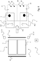
- FIG. 4 shows the schematic view of the embodiment of an inventive device 1 of the FIGS. 1 to 3 and illustrates a fourth step of an embodiment of a method according to the invention.
- the control device S is, as already mentioned above, the movements of the suction and / or gripping devices 3 in such a way that the intermediate layers 5 reach their respective predetermined destination Z1 or Z2 with a predetermined position.
- the directional components RK2 and RK2 face each other, so that the two intermediate layers 5 approach each other.
- the directional component RK1 of the movement is furthermore designed for both intermediate layers 5 or for both suction and / or gripping devices 3, so that the intermediate layers 5 move in the direction of their respective destination Z1 or Z2 move.
- the clamping elements 30 remain in their position and wait for the arrival of the intermediate layers 5 at their respective destination Z1 or Z2.
- the two stops 20 and 22 have moved away from each other and can temporally before receiving a further intermediate layer 5 of the intermediate layer stacks 7, the intermediate layers 5 of the intermediate layer stack 7 again align flush.
- a stop 22 provided for flush alignment of intermediate layers 5 and a stop 20 provided for flush alignment of intermediate layers 5 in this case come into surface contact both with intermediate layers 5 of a first of the two intermediate layer stacks 7 and with intermediate layers 5 of a second of the two intermediate layer stacks 7.
- FIG. 5 shows the schematic view of the embodiment of an inventive device 1 of the FIGS. 1 to 4 and illustrates a fourth step of an embodiment of a method according to the invention.
- the intermediate layers 5 have now reached their respective destination Z1 or Z2 with a predetermined position. Since the trajectory of the suction and / or gripping devices 3 in the direction of the respective destination Z1 or Z2 is given by the control device S, taking into account the optical detection of the outer edge 6 of the respective intermediate layer 5, the intermediate layers 5 the respective destination Z1 or Z2 reach very precisely with a certain position.
- FIG. 5 shows FIG. 5 a gap or gap 14, which is formed between the individual intermediate layers 5 at the destination Z1 or Z2. Since by means of the method or by means of the device 1 spacers 5 very precise or with predetermined target position are transferred to their destination Z1 or Z2, a desired dimensioning of the gap or distance 14 can be maintained very accurately. Over the course of adjacent outer edges 6 of the located in the destinations Z1 and Z2 intermediate layers 5, the distance 14 is formed constant. In further conceivable embodiments, provision may also be made for no gap or spacing 14 to be formed and for the intermediate layers 15 to be directly adjacent to one another in the destination location Z1 or Z2 and possibly in contact with one another.
Landscapes
- Engineering & Computer Science (AREA)
- Mechanical Engineering (AREA)
- De-Stacking Of Articles (AREA)
- Manipulator (AREA)
Claims (15)
- Procédé de manipulation de couches intermédiaires (5) individuelles, dans lequel procédé,- parmi au moins deux piles distinctes de couches intermédiaires (7), respectivement une couche intermédiaire (5) individuelle qui est disposée tout en haut sur la pile de couches intermédiaires (7) respective, est séparée,- les couches intermédiaires (5) individuelles séparées desdites au moins deux piles distinctes de couches intermédiaires (7) sont déplacées dans une zone de détection d'un ensemble de capteur (13), dans lequel chacune des couches intermédiaires (5) séparées entre dans une zone de détection d'un propre ensemble de capteur (13) et ledit propre ensemble de capteur (13) détecte au moyen de détection de préférence optique un bord extérieur (6) s'étendant dans la direction de déplacement de la couche intermédiaire (5) respective, et dans lequel,- ensuite, les couches intermédiaires (5) individuelles séparées se dirigent vers un lieu de destination (Z1, Z2) respectif en prenant en considération la détection respective de préférence optique de sorte que les couches intermédiaires (5) atteignent leur lieu de destination (Z1, Z2) respectif à position prédéterminée, le procédé étant caractérisé par le fait que- les couches intermédiaires (5) sont déplacées lors de la détection de préférence optique de leur bord extérieur (6) respectif.
- Procédé selon la revendication 1, dans lequel, avant de séparer les couches intermédiaires (5) individuelles desdites au moins deux piles distinctes de couches intermédiaires (7), leur bord avant (8) respectif adjacent au bord extérieur (6) et leur bord arrière (9) respectif adjacent au bord extérieur (6) sont alignés.
- Procédé selon la revendication 2, dans lequel, pour aligner, au moins deux butées (20, 22) aptes à être rapprochées sont guidées contre les bords avant et arrière (8, 9) d'une pluralité de couches intermédiaires (5) desdites au moins deux piles de couches intermédiaires (7) de sorte que, grâce à cela, lesdites plusieurs couches intermédiaires (5) de la pile de couches intermédiaires (7) respective sont alignées de manière à être à fleur les unes par rapport aux autres.
- Procédé selon la revendication 3, dans lequel une butée (22) prévue pour aligner des couches intermédiaires (5) de manière à être à fleur à l'avant et une butée (20) prévue pour aligner des couches intermédiaires (5) de manière à être à fleur à l'arrière alignent aussi bien une pluralité de couches intermédiaires (5) d'une première pile de couches intermédiaires (7) qu'une pluralité de couches intermédiaires (5) d'une deuxième pile de couches intermédiaires (7) de manière à ce qu'elles soient à fleur les unes par rapport aux autres.
- Procédé selon l'une ou plusieurs des revendications 1 à 4, dans lequel les couches intermédiaires (5) séparées sont déplacées dans la zone de détection de l'ensemble de capteur (13) qui lui est propre, en synchronisme temporel avec une première composante de direction (RK1) qui montre en direction du lieu de destination (Z1, Z2) et avec une deuxième composante de direction (RK2) qui est orientée perpendiculairement à la première composante de direction (RK1).
- Procédé selon l'une ou plusieurs des revendications 1 à 5, dans lequel les bords extérieurs (6) s'étendant dans la direction de déplacement des couches intermédiaires (5) séparées sont détectés chacun optiquement au moyen d'un barrage photoélectrique (15).
- Procédé selon la revendication 5, dans lequel les barrages photoélectriques (15) pour détecter de façon optique les bords extérieurs (6) s'étendant dans la direction de déplacement de la couche intermédiaire (5) émettent un faisceau laser.
- Procédé selon l'une ou plusieurs des revendications 1 à 7, dans lequel, à partir de la séparation de la pile de couches intermédiaires (7) respective, les couches intermédiaires (5) individuelles sont déplacées sans interruption jusqu'au lieu de destination (Z1, Z2).
- Procédé selon l'une ou plusieurs des revendications 1 à 8, dans lequel, après avoir atteint le lieu de destination (Z1, Z2) respectif, les couches intermédiaires (5) forment une distance (14) prédéterminée entre leurs bords extérieurs (6) directement adjacents, laquelle distance (14) est continuellement constante le long de leurs bords extérieurs (6) directement adjacents.
- Procédé selon l'une ou plusieurs des revendications 1 à 9, dans lequel, parmi lesdites au moins deux piles distinctes de couches intermédiaires (7), des couches intermédiaires (5) individuelles sont séparées au moins approximativement en synchronisme temporel, et/ou dans lequel les couches intermédiaires (5) séparées desdites au moins deux piles distinctes de couches intermédiaires (7) entrent dans la zone de détection du propre ensemble de capteur (13) au moins approximativement en synchronisme temporel, et/ou dans lequel les couches intermédiaires (5) individuelles séparées se dirigent au moins approximativement en synchronisme temporel vers leur lieu de destination (Z1, Z2) respectif.
- Dispositif (1) de manipulation de couches intermédiaires (5) individuelles et de mise en oeuvre d'un procédé selon l'une quelconque des revendications 1 à 10, comprenant- au moins deux dispositifs d'aspiration et/ou de préhension (3) qui sont déplaçables indépendamment l'un de l'autre et destinés à séparer une couche intermédiaire (5) individuelle d'une pile de couches intermédiaires (7) et à transférer la couche intermédiaire (5) séparée vers un lieu de destination (Z1, Z2), chacun desdits au moins deux dispositifs d'aspiration et/ou de préhension (3) déplaçables indépendamment l'un de l'autre est conçu pour séparer une couche intermédiaire (5) individuelle d'une propre pile de couches intermédiaires (7),- un propre ensemble de capteur (13) pour chacun desdits au moins deux dispositifs d'aspiration et/ou de préhension (3), par le biais duquel peut être détecté, au moyen de détection de préférence optique, un bord extérieur (6) respectif s'étendant dans la direction de déplacement des couches intermédiaires (5) séparées, ainsi qu'- un dispositif de commande (S) qui est en communication avec lesdits au moins deux dispositifs d'aspiration et/ou de préhension (3) et leur ensemble de capteur (13) respectif, dans lequel le dispositif de commande (S) peut prédéterminer les directions de déplacement desdits au moins deux dispositifs d'aspiration et/ou de préhension (3) indépendamment l'un de l'autre et en prenant en considération les détections de préférence optiques, de telle sorte que les couches intermédiaires (5) atteignent chacune leur lieu de destination (Z1, Z2) à position prédéterminée, caractérisé par le fait que le dispositif de commande (S) commande le mouvement de telle sorte que les couches intermédiaires (5) sont déplacées lors de la détection de préférence optique de leur bord extérieur (6) respectif.
- Dispositif selon la revendication 11, dans lequel ledit propre ensemble de capteur (13) d'au moins l'un desdits au moins deux dispositifs d'aspiration et/ou de préhension (3) comprend un ou plusieurs barrages photoélectriques (15).
- Dispositif selon la revendication 12, dans lequel ledit un ou lesdits plusieurs barrages photoélectriques comprennent au moins un émetteur réalisé en tant que laser.
- Dispositif selon l'une ou plusieurs des revendications 11 à 13, comprenant au moins deux butées (20, 22) qui peuvent être mises en contact avec une pluralité de couches intermédiaires (5) disposées tout en haut sur les piles de couches intermédiaires (7), au moyen d'un mouvement de rapprochement initié par le dispositif de commande (S), pour un alignement affleurant à l'avant.
- Dispositif selon l'une ou plusieurs des revendications 11 à 14, dans lequel le dispositif de commande (S) peut commander un déplacement desdits au moins deux dispositifs d'aspiration et/ou de préhension (3) de manière à ce que les couches intermédiaires (5) atteignent leur lieu de destination (Z1, Z2) respectif au moins approximativement en synchronisme temporel.
Priority Applications (1)
| Application Number | Priority Date | Filing Date | Title |
|---|---|---|---|
| SI201630489T SI3247659T1 (sl) | 2015-01-19 | 2016-01-15 | Postopek in naprava za ravnanje s posameznimi vmesnimi sloji |
Applications Claiming Priority (2)
| Application Number | Priority Date | Filing Date | Title |
|---|---|---|---|
| DE102015200734.0A DE102015200734A1 (de) | 2015-01-19 | 2015-01-19 | Verfahren und Vorrichtung zum Umgang mit einzelnen Zwischenlagen |
| PCT/EP2016/050728 WO2016116361A1 (fr) | 2015-01-19 | 2016-01-15 | Procédé et dispositif pour manipuler des couches intermédiaires individuelles |
Publications (2)
| Publication Number | Publication Date |
|---|---|
| EP3247659A1 EP3247659A1 (fr) | 2017-11-29 |
| EP3247659B1 true EP3247659B1 (fr) | 2019-08-21 |
Family
ID=55168256
Family Applications (1)
| Application Number | Title | Priority Date | Filing Date |
|---|---|---|---|
| EP16700729.3A Active EP3247659B1 (fr) | 2015-01-19 | 2016-01-15 | Procédé et dispositif pour manipuler des couches intermédiaires individuelles |
Country Status (6)
| Country | Link |
|---|---|
| US (1) | US10227187B2 (fr) |
| EP (1) | EP3247659B1 (fr) |
| CN (1) | CN107207166B (fr) |
| DE (1) | DE102015200734A1 (fr) |
| SI (1) | SI3247659T1 (fr) |
| WO (1) | WO2016116361A1 (fr) |
Families Citing this family (4)
| Publication number | Priority date | Publication date | Assignee | Title |
|---|---|---|---|---|
| DE102017111800A1 (de) | 2017-05-30 | 2018-12-06 | Wisco Lasertechnik Gmbh | Verfahren zur Ausrichtung zweier Werkstücke zur Ausbildung einer Fügeverbindung und Manipulator |
| JP7022084B2 (ja) * | 2019-01-24 | 2022-02-17 | アイダエンジニアリング株式会社 | ワーク搬送システム、搬送ワーク枚数検出装置及びワーク搬送システムの制御方法 |
| CN111776717B (zh) * | 2020-05-28 | 2021-08-31 | 杭州派祺空气净化科技有限公司 | 一种智能机械制造抓取设备 |
| IT202100016457A1 (it) * | 2021-06-23 | 2022-12-23 | Stevanato Group Spa | APPARATO PER il CONFEZIONAMENTO DI CONTENITORI DI DISPOSITIVI PER USO FARMACEUTICO |
Family Cites Families (32)
| Publication number | Priority date | Publication date | Assignee | Title |
|---|---|---|---|---|
| US4105925A (en) * | 1977-03-14 | 1978-08-08 | General Motors Corporation | Optical object locator |
| US4228886A (en) * | 1978-12-26 | 1980-10-21 | Ppg Industries, Inc. | Position sensor |
| US6317953B1 (en) * | 1981-05-11 | 2001-11-20 | Lmi-Diffracto | Vision target based assembly |
| US4547115A (en) * | 1984-01-25 | 1985-10-15 | Charbonnet Carl D | Apparatus for transporting and aligning panel-like members |
| US4797169A (en) * | 1986-07-02 | 1989-01-10 | Hashimoto Denki Co. Ltd. | Method and apparatus for assembling veneer sheet into a plywood |
| DE3702965A1 (de) * | 1987-02-02 | 1988-08-11 | Adolf Stambera | Einrichtung zum einlegen von zwischenlagen bei palettiermaschinen |
| DE4028981A1 (de) * | 1989-09-14 | 1991-03-28 | Ingo Dr Rer Nat Siewert | Verfahren und einrichtung zum positionieren von werkstuecken |
| JPH0742008B2 (ja) | 1991-10-25 | 1995-05-10 | 東洋自動機株式会社 | 自動包装機に対する空袋供給装置 |
| JPH11199071A (ja) | 1998-01-08 | 1999-07-27 | Daihatsu Motor Co Ltd | シート搬送装置 |
| US6155775A (en) | 1998-06-09 | 2000-12-05 | R. R. Donnelley & Sons Company | Destacking feeder |
| DE19859302B4 (de) * | 1998-12-22 | 2008-10-09 | Schuler Automation Gmbh & Co. Kg | Anlage für Metallblechplatinen, mit einer Vereinzelungsstation und mindestens einer dieser nachgeordneten Transportstation und/oder Behandlungsstation und/oder Bearbeitungsstation |
| DE10155596B4 (de) | 2001-11-13 | 2008-12-11 | Grenzebach Maschinenbau Gmbh | Einrichtung zum Stapeln von längs eines Plattenförderers herangeführten Platten |
| DE10223858A1 (de) * | 2002-03-28 | 2003-10-09 | Peter Wamhoff | Vorrichtung für die Beschickung und/oder Abstapelung einer Bearbeitungsvorrichtung |
| US7645111B2 (en) * | 2002-11-05 | 2010-01-12 | Central Glass Company, Limited | System for putting glass plates to target positions |
| US20040240981A1 (en) * | 2003-05-29 | 2004-12-02 | I-Scan Robotics | Robot stacking system for flat glass |
| DE102004031301B4 (de) | 2004-06-28 | 2006-11-09 | WINKLER + DüNNEBIER AG | Vorrichtung zum Einbringen von Zwischenlagen beim Palettieren |
| US20060099064A1 (en) * | 2004-11-08 | 2006-05-11 | Yaron Anaki | On-the-fly robotic stacking system for flat glass |
| JP4751664B2 (ja) | 2005-08-05 | 2011-08-17 | 株式会社京都製作所 | 空袋供給装置 |
| JP2008200744A (ja) * | 2007-02-22 | 2008-09-04 | Ihi Corp | ディスタックフィーダ |
| DE102007047405A1 (de) * | 2007-10-04 | 2009-04-23 | WINKLER+DüNNEBIER AG | Verfahren und Vorrichtung zum Bereitstellen unterschiedlicher Hilfsmaterialien durch einen Palettierroboter |
| ATE496711T1 (de) * | 2008-03-12 | 2011-02-15 | Schuler Automation Gmbh & Co | Vorrichtung und verfahren zur lageausrichtung von plattenförmigen teilen |
| SI2195267T2 (sl) * | 2008-03-12 | 2019-02-28 | Schuler Automation Gmbh & Co. Kg | Postopek za razkladanje ploščastih delov |
| JP5067250B2 (ja) * | 2008-04-18 | 2012-11-07 | 村田機械株式会社 | 板材搬送装置 |
| DE102008054813A1 (de) | 2008-12-17 | 2010-06-24 | Koenig & Bauer Aktiengesellschaft | Vorrichtung zum Ausrichtung von Bogen |
| DE202009000083U1 (de) * | 2009-02-04 | 2010-04-08 | Krones Ag | Vorrichtung zum Handhaben von flexiblem Flächenmaterial, flexibles Flächenmaterial und Palette |
| EP2399849A1 (fr) * | 2010-06-22 | 2011-12-28 | Winkler + Dünnebier AG | Dispositif et procédé de préparation de feuilles intermédiaires à un robot de palettisation |
| DE102012006273A1 (de) | 2012-03-29 | 2013-10-02 | Heidelberger Druckmaschinen Aktiengesellschaft | Verfahren und Vorrichtung zum Vereinzeln von Druckplatten von Druckplattenstapeln |
| US8826787B2 (en) * | 2012-08-22 | 2014-09-09 | Xerox Corporation | Cutting machine media feeder system with fixed in-feed and out-feed trays |
| DE102013101086A1 (de) * | 2013-02-04 | 2014-08-07 | Krones Aktiengesellschaft | Verfahren und Vorrichtung zum Palettieren von Stückgut-, Artikel- und/oder Gebindelagen |
| DE102013106012A1 (de) * | 2013-06-10 | 2014-12-11 | Krones Aktiengesellschaft | Verfahren und Vorrichtung zum Umgang mit Zwischenlagen |
| CN103342240B (zh) * | 2013-07-10 | 2016-01-20 | 深圳先进技术研究院 | 袋装物料装车系统和方法 |
| CN204038623U (zh) * | 2014-08-20 | 2014-12-24 | 安徽盛德机械制造有限公司 | 一种堆垛机 |
-
2015
- 2015-01-19 DE DE102015200734.0A patent/DE102015200734A1/de not_active Withdrawn
-
2016
- 2016-01-15 CN CN201680005507.3A patent/CN107207166B/zh active Active
- 2016-01-15 WO PCT/EP2016/050728 patent/WO2016116361A1/fr not_active Ceased
- 2016-01-15 EP EP16700729.3A patent/EP3247659B1/fr active Active
- 2016-01-15 US US15/543,411 patent/US10227187B2/en active Active
- 2016-01-15 SI SI201630489T patent/SI3247659T1/sl unknown
Non-Patent Citations (1)
| Title |
|---|
| None * |
Also Published As
| Publication number | Publication date |
|---|---|
| US20180002118A1 (en) | 2018-01-04 |
| DE102015200734A1 (de) | 2016-07-21 |
| CN107207166A (zh) | 2017-09-26 |
| WO2016116361A1 (fr) | 2016-07-28 |
| CN107207166B (zh) | 2019-07-05 |
| SI3247659T1 (sl) | 2019-12-31 |
| US10227187B2 (en) | 2019-03-12 |
| EP3247659A1 (fr) | 2017-11-29 |
Similar Documents
| Publication | Publication Date | Title |
|---|---|---|
| EP3260402B1 (fr) | Système empileur de caisses | |
| EP3247659B1 (fr) | Procédé et dispositif pour manipuler des couches intermédiaires individuelles | |
| EP3666696A1 (fr) | Dispositif et procede pour manipuler des couches de marchandises unitaires superposees | |
| EP3757042A1 (fr) | Dispositif et procédé de manipulation des marchandises de détail déplacées les unes après les autres dans au moins une rangée | |
| WO2018153695A1 (fr) | Procédé et dispositif servant à empiler des feuilles de matériau plates ainsi que presse d'impression et/ou vernisseuse | |
| EP2813448B1 (fr) | Procédé et dispositif de manutention de couches intermédiaires | |
| DE102017107215A1 (de) | Verfahren zur Bewegung eines zur Handhabung von flächigen Zuschnitten ausgebildeten Saug- und/oder Greifinstrumentes sowie Vorrichtung mit einem solchen Saug- und/oder Greifinstrument | |
| EP3247662B1 (fr) | Procédé et dispositif permettant de séparer des couches intermédiaires individuelles d'une pile de couches intermédiaires | |
| EP3241791B1 (fr) | Procédé de fabrication d'empilements de feuilles | |
| EP3247660B1 (fr) | Procédé et dispositif de manipulation des couches intermédiaires individuelles | |
| EP2243732A2 (fr) | Dispositif et procédé destinés à transférer des gerbes ou des couches d'articles dans une station de chargement | |
| DE102012021268A1 (de) | Verfahren und Vorrichtung zur Bildung eines Hilfsstapels | |
| DE102015200731A1 (de) | Verfahren und Vorrichtung zum Umgang mit einzelnen Zwischenlagen | |
| EP2029360B1 (fr) | Procédé et dispositif de fabrication de films composites | |
| DE102015119321A1 (de) | Vorrichtung und Verfahren zum Umgang mit Stückgütern mit einer hiermit in Zusammenhang stehenden Erzeugung und Handhabung von Zwischenlagen | |
| EP3529183B1 (fr) | Procédé et dispositif pour la manutention de découpes planes d'une pile comprenant une pluralité de découpes planes | |
| EP3024767A1 (fr) | Palette d'adaptation pour dispositif d'empilage | |
| DE102015200725A1 (de) | Vorrichtung und Verfahren zum Trennen einzelner Zwischenlagen von einem Zwischenlagenstapel | |
| DE102015108966A1 (de) | Verfahren und Vorrichtung zum Umgang mit einzelnen Zwischenlagen | |
| DE102015200727B4 (de) | Vorrichtung und Verfahren zum Positionieren einzelner Zwischenlagen eines Zwischenlagenstapels auf zugeordneten Paletten | |
| DE102015103481A1 (de) | Verfahren und Vorrichtung zum Umgang mit einzelnen Zwischenlagen | |
| EP3907163A1 (fr) | Applicateur pour empilements de supports plats | |
| DE102023131908B4 (de) | Bearbeitungsmaschine | |
| WO2016116366A1 (fr) | Procédé et dispositif servant à séparer les couches intermédiaires individuelles d'une pile de couches intermédiaires | |
| EP3694796B1 (fr) | Arrangement et procédé de manutention de marchandises à la pièce déplacées dans au moins trois rangées |
Legal Events
| Date | Code | Title | Description |
|---|---|---|---|
| STAA | Information on the status of an ep patent application or granted ep patent |
Free format text: STATUS: THE INTERNATIONAL PUBLICATION HAS BEEN MADE |
|
| PUAI | Public reference made under article 153(3) epc to a published international application that has entered the european phase |
Free format text: ORIGINAL CODE: 0009012 |
|
| STAA | Information on the status of an ep patent application or granted ep patent |
Free format text: STATUS: REQUEST FOR EXAMINATION WAS MADE |
|
| 17P | Request for examination filed |
Effective date: 20170726 |
|
| AK | Designated contracting states |
Kind code of ref document: A1 Designated state(s): AL AT BE BG CH CY CZ DE DK EE ES FI FR GB GR HR HU IE IS IT LI LT LU LV MC MK MT NL NO PL PT RO RS SE SI SK SM TR |
|
| AX | Request for extension of the european patent |
Extension state: BA ME |
|
| DAV | Request for validation of the european patent (deleted) | ||
| DAX | Request for extension of the european patent (deleted) | ||
| STAA | Information on the status of an ep patent application or granted ep patent |
Free format text: STATUS: EXAMINATION IS IN PROGRESS |
|
| 17Q | First examination report despatched |
Effective date: 20180802 |
|
| GRAP | Despatch of communication of intention to grant a patent |
Free format text: ORIGINAL CODE: EPIDOSNIGR1 |
|
| STAA | Information on the status of an ep patent application or granted ep patent |
Free format text: STATUS: GRANT OF PATENT IS INTENDED |
|
| INTG | Intention to grant announced |
Effective date: 20190321 |
|
| GRAS | Grant fee paid |
Free format text: ORIGINAL CODE: EPIDOSNIGR3 |
|
| GRAA | (expected) grant |
Free format text: ORIGINAL CODE: 0009210 |
|
| STAA | Information on the status of an ep patent application or granted ep patent |
Free format text: STATUS: THE PATENT HAS BEEN GRANTED |
|
| AK | Designated contracting states |
Kind code of ref document: B1 Designated state(s): AL AT BE BG CH CY CZ DE DK EE ES FI FR GB GR HR HU IE IS IT LI LT LU LV MC MK MT NL NO PL PT RO RS SE SI SK SM TR |
|
| REG | Reference to a national code |
Ref country code: GB Ref legal event code: FG4D Free format text: NOT ENGLISH |
|
| REG | Reference to a national code |
Ref country code: CH Ref legal event code: EP |
|
| REG | Reference to a national code |
Ref country code: DE Ref legal event code: R096 Ref document number: 502016006182 Country of ref document: DE |
|
| REG | Reference to a national code |
Ref country code: AT Ref legal event code: REF Ref document number: 1169510 Country of ref document: AT Kind code of ref document: T Effective date: 20190915 |
|
| REG | Reference to a national code |
Ref country code: IE Ref legal event code: FG4D Free format text: LANGUAGE OF EP DOCUMENT: GERMAN |
|
| REG | Reference to a national code |
Ref country code: LT Ref legal event code: MG4D |
|
| REG | Reference to a national code |
Ref country code: NL Ref legal event code: MP Effective date: 20190821 |
|
| PG25 | Lapsed in a contracting state [announced via postgrant information from national office to epo] |
Ref country code: BG Free format text: LAPSE BECAUSE OF FAILURE TO SUBMIT A TRANSLATION OF THE DESCRIPTION OR TO PAY THE FEE WITHIN THE PRESCRIBED TIME-LIMIT Effective date: 20191121 Ref country code: NL Free format text: LAPSE BECAUSE OF FAILURE TO SUBMIT A TRANSLATION OF THE DESCRIPTION OR TO PAY THE FEE WITHIN THE PRESCRIBED TIME-LIMIT Effective date: 20190821 Ref country code: NO Free format text: LAPSE BECAUSE OF FAILURE TO SUBMIT A TRANSLATION OF THE DESCRIPTION OR TO PAY THE FEE WITHIN THE PRESCRIBED TIME-LIMIT Effective date: 20191121 Ref country code: SE Free format text: LAPSE BECAUSE OF FAILURE TO SUBMIT A TRANSLATION OF THE DESCRIPTION OR TO PAY THE FEE WITHIN THE PRESCRIBED TIME-LIMIT Effective date: 20190821 Ref country code: LT Free format text: LAPSE BECAUSE OF FAILURE TO SUBMIT A TRANSLATION OF THE DESCRIPTION OR TO PAY THE FEE WITHIN THE PRESCRIBED TIME-LIMIT Effective date: 20190821 Ref country code: PT Free format text: LAPSE BECAUSE OF FAILURE TO SUBMIT A TRANSLATION OF THE DESCRIPTION OR TO PAY THE FEE WITHIN THE PRESCRIBED TIME-LIMIT Effective date: 20191223 Ref country code: HR Free format text: LAPSE BECAUSE OF FAILURE TO SUBMIT A TRANSLATION OF THE DESCRIPTION OR TO PAY THE FEE WITHIN THE PRESCRIBED TIME-LIMIT Effective date: 20190821 Ref country code: FI Free format text: LAPSE BECAUSE OF FAILURE TO SUBMIT A TRANSLATION OF THE DESCRIPTION OR TO PAY THE FEE WITHIN THE PRESCRIBED TIME-LIMIT Effective date: 20190821 |
|
| PG25 | Lapsed in a contracting state [announced via postgrant information from national office to epo] |
Ref country code: LV Free format text: LAPSE BECAUSE OF FAILURE TO SUBMIT A TRANSLATION OF THE DESCRIPTION OR TO PAY THE FEE WITHIN THE PRESCRIBED TIME-LIMIT Effective date: 20190821 Ref country code: ES Free format text: LAPSE BECAUSE OF FAILURE TO SUBMIT A TRANSLATION OF THE DESCRIPTION OR TO PAY THE FEE WITHIN THE PRESCRIBED TIME-LIMIT Effective date: 20190821 Ref country code: AL Free format text: LAPSE BECAUSE OF FAILURE TO SUBMIT A TRANSLATION OF THE DESCRIPTION OR TO PAY THE FEE WITHIN THE PRESCRIBED TIME-LIMIT Effective date: 20190821 Ref country code: IS Free format text: LAPSE BECAUSE OF FAILURE TO SUBMIT A TRANSLATION OF THE DESCRIPTION OR TO PAY THE FEE WITHIN THE PRESCRIBED TIME-LIMIT Effective date: 20191221 Ref country code: RS Free format text: LAPSE BECAUSE OF FAILURE TO SUBMIT A TRANSLATION OF THE DESCRIPTION OR TO PAY THE FEE WITHIN THE PRESCRIBED TIME-LIMIT Effective date: 20190821 Ref country code: GR Free format text: LAPSE BECAUSE OF FAILURE TO SUBMIT A TRANSLATION OF THE DESCRIPTION OR TO PAY THE FEE WITHIN THE PRESCRIBED TIME-LIMIT Effective date: 20191122 |
|
| PG25 | Lapsed in a contracting state [announced via postgrant information from national office to epo] |
Ref country code: TR Free format text: LAPSE BECAUSE OF FAILURE TO SUBMIT A TRANSLATION OF THE DESCRIPTION OR TO PAY THE FEE WITHIN THE PRESCRIBED TIME-LIMIT Effective date: 20190821 |
|
| PG25 | Lapsed in a contracting state [announced via postgrant information from national office to epo] |
Ref country code: RO Free format text: LAPSE BECAUSE OF FAILURE TO SUBMIT A TRANSLATION OF THE DESCRIPTION OR TO PAY THE FEE WITHIN THE PRESCRIBED TIME-LIMIT Effective date: 20190821 Ref country code: PL Free format text: LAPSE BECAUSE OF FAILURE TO SUBMIT A TRANSLATION OF THE DESCRIPTION OR TO PAY THE FEE WITHIN THE PRESCRIBED TIME-LIMIT Effective date: 20190821 Ref country code: EE Free format text: LAPSE BECAUSE OF FAILURE TO SUBMIT A TRANSLATION OF THE DESCRIPTION OR TO PAY THE FEE WITHIN THE PRESCRIBED TIME-LIMIT Effective date: 20190821 Ref country code: DK Free format text: LAPSE BECAUSE OF FAILURE TO SUBMIT A TRANSLATION OF THE DESCRIPTION OR TO PAY THE FEE WITHIN THE PRESCRIBED TIME-LIMIT Effective date: 20190821 |
|
| PG25 | Lapsed in a contracting state [announced via postgrant information from national office to epo] |
Ref country code: IS Free format text: LAPSE BECAUSE OF FAILURE TO SUBMIT A TRANSLATION OF THE DESCRIPTION OR TO PAY THE FEE WITHIN THE PRESCRIBED TIME-LIMIT Effective date: 20200224 Ref country code: SM Free format text: LAPSE BECAUSE OF FAILURE TO SUBMIT A TRANSLATION OF THE DESCRIPTION OR TO PAY THE FEE WITHIN THE PRESCRIBED TIME-LIMIT Effective date: 20190821 Ref country code: CZ Free format text: LAPSE BECAUSE OF FAILURE TO SUBMIT A TRANSLATION OF THE DESCRIPTION OR TO PAY THE FEE WITHIN THE PRESCRIBED TIME-LIMIT Effective date: 20190821 Ref country code: SK Free format text: LAPSE BECAUSE OF FAILURE TO SUBMIT A TRANSLATION OF THE DESCRIPTION OR TO PAY THE FEE WITHIN THE PRESCRIBED TIME-LIMIT Effective date: 20190821 |
|
| REG | Reference to a national code |
Ref country code: DE Ref legal event code: R097 Ref document number: 502016006182 Country of ref document: DE |
|
| PLBE | No opposition filed within time limit |
Free format text: ORIGINAL CODE: 0009261 |
|
| STAA | Information on the status of an ep patent application or granted ep patent |
Free format text: STATUS: NO OPPOSITION FILED WITHIN TIME LIMIT |
|
| PG2D | Information on lapse in contracting state deleted |
Ref country code: IS |
|
| 26N | No opposition filed |
Effective date: 20200603 |
|
| PG25 | Lapsed in a contracting state [announced via postgrant information from national office to epo] |
Ref country code: MC Free format text: LAPSE BECAUSE OF FAILURE TO SUBMIT A TRANSLATION OF THE DESCRIPTION OR TO PAY THE FEE WITHIN THE PRESCRIBED TIME-LIMIT Effective date: 20190821 |
|
| REG | Reference to a national code |
Ref country code: CH Ref legal event code: PL |
|
| GBPC | Gb: european patent ceased through non-payment of renewal fee |
Effective date: 20200115 |
|
| REG | Reference to a national code |
Ref country code: BE Ref legal event code: MM Effective date: 20200131 |
|
| PG25 | Lapsed in a contracting state [announced via postgrant information from national office to epo] |
Ref country code: GB Free format text: LAPSE BECAUSE OF NON-PAYMENT OF DUE FEES Effective date: 20200115 Ref country code: LU Free format text: LAPSE BECAUSE OF NON-PAYMENT OF DUE FEES Effective date: 20200115 |
|
| PG25 | Lapsed in a contracting state [announced via postgrant information from national office to epo] |
Ref country code: CH Free format text: LAPSE BECAUSE OF NON-PAYMENT OF DUE FEES Effective date: 20200131 Ref country code: LI Free format text: LAPSE BECAUSE OF NON-PAYMENT OF DUE FEES Effective date: 20200131 Ref country code: BE Free format text: LAPSE BECAUSE OF NON-PAYMENT OF DUE FEES Effective date: 20200131 |
|
| PG25 | Lapsed in a contracting state [announced via postgrant information from national office to epo] |
Ref country code: IE Free format text: LAPSE BECAUSE OF NON-PAYMENT OF DUE FEES Effective date: 20200115 |
|
| REG | Reference to a national code |
Ref country code: AT Ref legal event code: MM01 Ref document number: 1169510 Country of ref document: AT Kind code of ref document: T Effective date: 20210115 |
|
| PG25 | Lapsed in a contracting state [announced via postgrant information from national office to epo] |
Ref country code: AT Free format text: LAPSE BECAUSE OF NON-PAYMENT OF DUE FEES Effective date: 20210115 |
|
| PG25 | Lapsed in a contracting state [announced via postgrant information from national office to epo] |
Ref country code: MT Free format text: LAPSE BECAUSE OF FAILURE TO SUBMIT A TRANSLATION OF THE DESCRIPTION OR TO PAY THE FEE WITHIN THE PRESCRIBED TIME-LIMIT Effective date: 20190821 Ref country code: CY Free format text: LAPSE BECAUSE OF FAILURE TO SUBMIT A TRANSLATION OF THE DESCRIPTION OR TO PAY THE FEE WITHIN THE PRESCRIBED TIME-LIMIT Effective date: 20190821 |
|
| PG25 | Lapsed in a contracting state [announced via postgrant information from national office to epo] |
Ref country code: MK Free format text: LAPSE BECAUSE OF FAILURE TO SUBMIT A TRANSLATION OF THE DESCRIPTION OR TO PAY THE FEE WITHIN THE PRESCRIBED TIME-LIMIT Effective date: 20190821 |
|
| P01 | Opt-out of the competence of the unified patent court (upc) registered |
Effective date: 20230523 |
|
| REG | Reference to a national code |
Ref country code: DE Ref legal event code: R082 Ref document number: 502016006182 Country of ref document: DE Representative=s name: BENNINGER, JOHANNES, DIPL.-ING., DE |
|
| PGFP | Annual fee paid to national office [announced via postgrant information from national office to epo] |
Ref country code: FR Payment date: 20251208 Year of fee payment: 11 |
|
| PGFP | Annual fee paid to national office [announced via postgrant information from national office to epo] |
Ref country code: SI Payment date: 20251215 Year of fee payment: 11 |
|
| PGFP | Annual fee paid to national office [announced via postgrant information from national office to epo] |
Ref country code: DE Payment date: 20251203 Year of fee payment: 11 |
|
| PGFP | Annual fee paid to national office [announced via postgrant information from national office to epo] |
Ref country code: IT Payment date: 20251219 Year of fee payment: 11 |