EP3247663B1 - Verfahren zur verteilung von klebstoff auf rohrförmigen pappkernen in umwicklungsmaschinen - Google Patents
Verfahren zur verteilung von klebstoff auf rohrförmigen pappkernen in umwicklungsmaschinen Download PDFInfo
- Publication number
- EP3247663B1 EP3247663B1 EP15820298.6A EP15820298A EP3247663B1 EP 3247663 B1 EP3247663 B1 EP 3247663B1 EP 15820298 A EP15820298 A EP 15820298A EP 3247663 B1 EP3247663 B1 EP 3247663B1
- Authority
- EP
- European Patent Office
- Prior art keywords
- glue
- nozzles
- cores
- pump
- amount
- Prior art date
- Legal status (The legal status is an assumption and is not a legal conclusion. Google has not performed a legal analysis and makes no representation as to the accuracy of the status listed.)
- Active
Links
Images


Classifications
-
- B—PERFORMING OPERATIONS; TRANSPORTING
- B65—CONVEYING; PACKING; STORING; HANDLING THIN OR FILAMENTARY MATERIAL
- B65H—HANDLING THIN OR FILAMENTARY MATERIAL, e.g. SHEETS, WEBS, CABLES
- B65H19/00—Changing the web roll
- B65H19/22—Changing the web roll in winding mechanisms or in connection with winding operations
- B65H19/28—Attaching the leading end of the web to the replacement web-roll core or spindle
- B65H19/283—Attaching the leading end of the web to the replacement web-roll core or spindle by applying adhesive to the core
-
- B—PERFORMING OPERATIONS; TRANSPORTING
- B05—SPRAYING OR ATOMISING IN GENERAL; APPLYING FLUENT MATERIALS TO SURFACES, IN GENERAL
- B05B—SPRAYING APPARATUS; ATOMISING APPARATUS; NOZZLES
- B05B1/00—Nozzles, spray heads or other outlets, with or without auxiliary devices such as valves, heating means
- B05B1/14—Nozzles, spray heads or other outlets, with or without auxiliary devices such as valves, heating means with multiple outlet openings; with strainers in or outside the outlet opening
- B05B1/20—Perforated pipes or troughs, e.g. spray booms; Outlet elements therefor
- B05B1/205—Perforated pipes or troughs, e.g. spray booms; Outlet elements therefor characterised by the longitudinal shape of the elongated body
-
- B—PERFORMING OPERATIONS; TRANSPORTING
- B05—SPRAYING OR ATOMISING IN GENERAL; APPLYING FLUENT MATERIALS TO SURFACES, IN GENERAL
- B05B—SPRAYING APPARATUS; ATOMISING APPARATUS; NOZZLES
- B05B1/00—Nozzles, spray heads or other outlets, with or without auxiliary devices such as valves, heating means
- B05B1/30—Nozzles, spray heads or other outlets, with or without auxiliary devices such as valves, heating means designed to control volume of flow, e.g. with adjustable passages
-
- B—PERFORMING OPERATIONS; TRANSPORTING
- B05—SPRAYING OR ATOMISING IN GENERAL; APPLYING FLUENT MATERIALS TO SURFACES, IN GENERAL
- B05B—SPRAYING APPARATUS; ATOMISING APPARATUS; NOZZLES
- B05B12/00—Arrangements for controlling delivery; Arrangements for controlling the spray area
- B05B12/02—Arrangements for controlling delivery; Arrangements for controlling the spray area for controlling time, or sequence, of delivery
-
- B—PERFORMING OPERATIONS; TRANSPORTING
- B05—SPRAYING OR ATOMISING IN GENERAL; APPLYING FLUENT MATERIALS TO SURFACES, IN GENERAL
- B05B—SPRAYING APPARATUS; ATOMISING APPARATUS; NOZZLES
- B05B9/00—Spraying apparatus for discharge of liquids or other fluent material, without essentially mixing with gas or vapour
- B05B9/03—Spraying apparatus for discharge of liquids or other fluent material, without essentially mixing with gas or vapour characterised by means for supplying liquid or other fluent material
- B05B9/04—Spraying apparatus for discharge of liquids or other fluent material, without essentially mixing with gas or vapour characterised by means for supplying liquid or other fluent material with pressurised or compressible container; with pump
-
- B—PERFORMING OPERATIONS; TRANSPORTING
- B65—CONVEYING; PACKING; STORING; HANDLING THIN OR FILAMENTARY MATERIAL
- B65H—HANDLING THIN OR FILAMENTARY MATERIAL, e.g. SHEETS, WEBS, CABLES
- B65H19/00—Changing the web roll
- B65H19/22—Changing the web roll in winding mechanisms or in connection with winding operations
- B65H19/2238—The web roll being driven by a winding mechanism of the nip or tangential drive type
- B65H19/2269—Cradle
-
- B—PERFORMING OPERATIONS; TRANSPORTING
- B65—CONVEYING; PACKING; STORING; HANDLING THIN OR FILAMENTARY MATERIAL
- B65H—HANDLING THIN OR FILAMENTARY MATERIAL, e.g. SHEETS, WEBS, CABLES
- B65H2701/00—Handled material; Storage means
- B65H2701/10—Handled articles or webs
- B65H2701/17—Nature of material
- B65H2701/176—Cardboard
Definitions
- the present invention relates to a method for distributing glue on tubular cardboard cores in rewinding machines, in particular for the production of rolls or "logs" of paper material.
- logs implies, in addition, the use of winding rollers downstream of the glue distribution station, which make each core to rotate around its own longitudinal axis thus determining the winding of the web on the core.
- the process ends when a preset number of sheets is wound on the core, with the gluing of a flap of the last sheet on the underlying one of the roll thus formed (so-called "flap closure operation"). At this point, the log is discharged from the rewinder.
- EP1519886 discloses a rewinding machine that operates according to the scheme described above.
- US7469856 and EP 1679274 disclose sizing systems for the production of logs in which the glue is applied to the cores from the bottom and the excess of glue falls back into the same tank containing the glue, causing possible contamination of the glue with particles of paper material and, thus, compromising the quality of the glueing step.
- US2003/0047639 discloses a rewinder provided with a device comprising a series of nozzles located above a path followed by the tubular cores introduced in the rewinder. These nozzles spray glue on the cores that pass along said path. Since the glue is sprayed on the surface of the cores, the glueing is necessarily imprecise.
- EP1541245 discloses a device for applying glue to the cores or to the end flap of a paper log with a glue applicator formed by a wire wound in a closed circuit on at least two pulleys which returns to a tank the glue that is not absorbed by the paper and, therefore, implies the contamination of the glue in the tank because it constitutes a carrier for the dust released by the paper of the web and the carboard of the cores.
- EP2045201 discloses a rewinder for making paper logs with a glueing device comprising a glue sprayer destined to spray glue on the cores at a waiting position upstream of a cradle above which winding rollers are provided. Since the glue is sprayed on the surface of the cores, the glueing is necessarily imprecise.
- the main purpose of the present invention is to eliminate the aforesaid drawbacks and to provide a glueing system that meets the current production needs without, however, introduce structural or functional complications or higher costs linked to the production of the system itself or the production of the paper logs.
- the present glueing system offers the possibility to ensure a fast flow of the cores at the entrance of the rewinders and to reduce as much as possible the consumption of the glue without compromising the quality of the glueing.
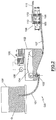
- a device for the implementation of a method in accordance with the present invention can be used, for example, in a rewinder (RW) of the type comprising:
- the first winder roller (R4) also has the function of guiding the paper web (2) coming from the supply and pre-cutting rollers.
- the aforesaid channel (CH) delimits the last leg of the path followed by the paper web (2) and also of the cores (1) exiting from the glueing device (GD).
- the glueing device comprises a glue supply unit (GS) and a glue distribution unit (GD).
- the supply unit (GS) feeds the glue to the distribution unit (GD), which then distribute it, from above, on the cores (1).
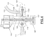
- the supply unit (GS) comprises a first reservoir (100) in which is stored the glue (G) and which is connected, by a pipe (101), to a second tank (102) provided with a valve (103) controlled by a float (104) to maintain constant the level of the glue inside it.
- the valve (103) and the float (104) are known per se.
- the second tank (102) is depressed, to facilitate the degassing of the glue (G).
- the second tank (102) has an output connected, via a corresponding conduit (107), with a pump (108) provided with intake and outlet valves (109, 110). Also the pump (108) is of the known type. In particular, it is a double cylinder pneumatic pump.
- the output of the pump (108) is connected, via a further duct (111), with the glue distribution unit (GD).
- conduit (111) connects the pump (108) with the input of a regulator valve (112) which in turn is connected, on its exit, with a distributor (119) on which are mounted more nozzles (114) from which comes out the glue intended to be applied on the tubular cores (1) intended for rewinder and transiting below the same nozzles (114).
- the control valve (112) serves to adjust the pressure and, separately, the flow of the glue that arrives to the nozzles (114) and, for this purpose, is provided with independent means for adjusting the pressure and flow rate of the glue.
- the valve (112) has an inlet (112A) in which is inserted the output of the conduit (111), an output (112B) in which is inserted the input of the duct (113), and an inner chamber (112C) that connects the input (112A) with the output (112B) and in which inner chamber passes the glue coming from the duct (111), or from the pump (108).
- the glue flow rate is adjusted using a screw (115) operable by means of a corresponding electric actuator (116) that can be controlled by the operator via a keyboard (not shown in the drawings) or by program in function of preset values. In this way, it is possible to regulate the amount of glue dispensed through the nozzles (114) over the time.
- the screw (115) acts in the internal cavity (112C) of the valve (112).
- a pneumatically actuated pressure multiplier (MP) whose rod (117) acts in the chamber (112C) and is controlled by a resisting spring (118).
- MP pneumatically actuated pressure multiplier
- a non-return valve (124) structured and functioning in a per se known manner, with adjustment screw (120) and counter-spring (121) invested on the screw (120) which acts with its front end on a closure member (122) inserted on the output of a chamber (123) of the valve (124) where the controller (115) and the pressure multiplier (116) exert their action. Therefore, in the output section (112 B) of the valve (112) the glue is supplied at separately adjustable pressure and flow rate.
- the conduit (113) supplies the nozzles (114) grafted on the distributor (119) that receives the glue from the valve (112). More particularly, the conduit (113) is connected to the distributor (119) by means of a vertical rigid tube (113B) which, over the relative engagement point (C), presents a vent for the air (SA1). At the bottom, the tube (113B) is connected on an input section of the distributor (119) . The latter is provided with internal channels (1190) that connect the aforementioned input section with each of the nozzles (114). Channels (1190) are internal to the distributor (119) and are connected to two air vents (SA2), or to a vent (SA2) on each side, right and left, of the distributor (119). It goes without saying that the number of vents (SA2) may be different from that now indicated.
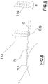
- the nozzles (114) grafted on the tube (119) are aligned along a same straight direction orthogonal to the direction (A) along which the tubes (1) advance.
- the glue distribution unit may also comprise two distributors (119) with respective nozzles (114) so as to form two batteries of nozzles (114) spaced apart by a predetermined value along the direction (A) and so as to dispense glue on tubes (1), depending on the specific processing to be performed, both through a first that through a second battery of nozzles.
- a hydraulic accumulator (125) connected between the pump (108) and the valve (112) that can serve to ensure a constant or substantially constant pressure of the fluid introduced into the valve (112).
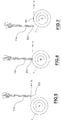
- the nozzles (114) are capillary tubes at the exit of which it forms a drop (EG) with a speed that can vary in function of the geometric features of the same nozzles.
- said nozzles (114) are mounted in a removable manner on the distributor (119) to be able to vary, if necessary, the capillary behavior, that is, the rate of formation of the drop of glue, by simply replacing nozzles having a certain geometry (in particular, length and internal diameter) with others having a different geometry.
- the amount of glue dispensed by each nozzle (114), that is, the volume of the drops (EG), is such as to avoid that the drops falling in the time interval that elapses between the passage of a core (1) and the subsequent core under the nozzles (114).
- This is favored by the concave shape (with the concavity facing downwards) of the terminal part of the nozzles (114).
- the terminal part of the nozzles (114) is conical, with an opening angle (a) comprised, for example, between 45° and 100°, and preferably equal to 90°.
- the nozzles (114) are suitably arranged in such a way that the distance (h) between the lower base of the same nozzles and the upper side (1D) of the cores that advance beneath them is such as to enable the cores (1) to transit freely while intercepting the glue (EG).
- said “h” the distance between the upper side(1D) of the cores (1) transiting below the nozzles (114) and the output of the nozzles (114), and said “g” the height of the drop (EG) produced by any of the nozzles (114), "g” and “h” are of the same order of magnitude.
- “h” has a value comprised between 0 and 1 mm
- “g” has a value comprised between 2 and 3 mm.
- the path followed by the cores (1) is such that the top side of the same cores (1), while these advance under the nozzles (114), intercepts the glue (EG), coming out by the nozzles themselves.
- the glue (EG) transfers by the nozzles (114) to the cores (1) without involving any intermediate member, that is, directly, and without being sprayed.
- the glue (EG) is on the surface of the cores (1) and on the output of the nozzles (114).
- the glue (EG), delivered by the nozzles (114) wets the outer surface of the cores (1) without that any contact between the nozzles and the cores but, unlike the spraying, the surface of the cores (1) wet by the glue (EG) will be more defined.
- the duration of the phase of glueing depends on the speed of the cores (1).
- several batteries of nozzles (114) can be arranged one after the other, with a predetermined interval along the direction (A) followed by the cores (1).
- the glue used for the implementation of this operating method is that normally used in the production of logs made of paper material.
- the glue dispensing circuit is preferably constituted by rigid elements, that is, substantially non-deformable elements, in relation to the working pressures so as to allow a regular outflow of the glue from the nozzles (114), avoiding glue feeding irregularities.
- the volume of the glue contained in the feed conduits is substantially constant.
- An operating method in accordance with the present invention includes the following steps:
- the nozzles (114) act as applicators of glue on the cores (1).
Landscapes
- Making Paper Articles (AREA)
- Application Of Or Painting With Fluid Materials (AREA)
- Storage Of Web-Like Or Filamentary Materials (AREA)
- Coating Apparatus (AREA)
Claims (17)
- Verfahren zum Auftragen von Kleber auf röhrenförmigen Kernen für die Erzeugung von Rollen aus Papiermaterial, umfassend den Schritt zum Zuführen in Abfolge mehrerer röhrenförmiger Kerne (1) entlang einer vorgegebenen Vorschubrichtung (A) und den Schritt zum Auftragen an jedem der Kerne (1) einer vorgegebenen Klebstoffmenge, und dass der Klebstoff auf die röhrenförmigen Kerne (1) von oben aufgetragen wird, dadurch gekennzeichnet, dass während Vorschubs entlang der Richtung (A) und ohne deren Bewegung zu unterbrechen, die röhrenförmigen Kerne (1) für eine vorgegebene Zeit den Klebstoff (EG) abfangen, der von einer vorgegebenen Zahl von Düsen (114) abgegeben wird; und während des Zeitintervalls der Kleber (EG) sowohl an den Düsen (114) als auch den röhrenförmigen Kernen (1) ist, die Abwesenheit eines Elements vorausgesetzt, das zwischen den Düsen und den röhrenförmigen Kernen eingefügt ist.
- Verfahren nach Anspruch 1, dadurch gekennzeichnet, dass es einen vorbereitenden Schritt zum Einstellen der Menge und/oder des Drucks des Klebstoffs involviert, der auf die Kerne (1) aufgetragen wird.
- Verfahren nach Anspruch 1, dadurch gekennzeichnet, dass die Klebemittel mindestens eine Batterie von Düsen (114) umfassen, die von einer Klebstoffverteilungseinheit (GD) gespeist werden, die Einstellmittel (112) umfasst, die zum Einstellen der Menge und/oder des Drucks des Klebstoffs angepasst sind.
- Verfahren nach Anspruch 3, dadurch gekennzeichnet, dass die Klebstoffverteilungseinheit (GD) den Klebstoff von einer Zufuhreinheit (GS) empfängt, die eine Pumpe (108) umfasst, die die Klebstoffverteilungseinheit (GD) speist.
- Verfahren nach Anspruch 4, dadurch gekennzeichnet, dass die Pumpe (108) den Klebstoff von einem druckentlasteten Tank (102) empfängt.
- Verfahren nach Anspruch 3 und 4, dadurch gekennzeichnet, dass die Einstellmittel ein Stellventil (112) umfassen, das stromabwärts der Pumpe (108) positioniert ist.
- Verfahren nach Anspruch 3 und 4, dadurch gekennzeichnet, dass ein hydraulischer Akkumulator (125) zwischen der Pumpe (108) und den Einstellmitteln (112) angeordnet ist und agiert.
- Verfahren nach Anspruch 1, dadurch gekennzeichnet, dass die Klebstoffmenge, die von den Düsen (114) abgegeben wird, im Laufe der Zeit konstant ist.
- Verfahren nach einem der vorstehenden Ansprüche, dadurch gekennzeichnet, dass die Düsen (114) durch Kapillarröhren gebildet sind.
- Verfahren nach einem oder mehreren der vorstehenden Ansprüche, dadurch gekennzeichnet, dass der Klebstoff (EG), der von jeder Düse (114) abgegeben wird, am Ausgang derselben Düse bleibt, ohne abzufallen, in dem Zeitintervall, das zwischen dem Durchlauf eines Kerns (1) und dem Durchlauf des nachfolgenden Kerns entlang der Vorschubrichtung (A) vergeht.
- Verfahren nach einem oder mehreren der vorstehenden Ansprüche, wobei der Klebstoff in der Form von Klebstofftropfen von den Düsen (114) geliefert wird, dadurch gekennzeichnet, dass das "h" der Abstand zwischen der Außenfläche (1D) der Kerne (1), die unter den Düsen (114) durchlaufen, und dem Ausgang der Düsen (114) ist und "g" die Höhe der Klebstofftropfen (EG) ist, die durch eine der Düsen (114) erzeugt werden, wobei "g" und "h" dieselbe Größenordnung sind.
- Verfahren nach einem oder mehreren der vorstehenden Ansprüche, dadurch gekennzeichnet, dass die Düsen (114) auf eine abnehmbare Weise an einen Träger (119) angebracht sind.
- Verfahren nach einem oder mehreren der vorstehenden Ansprüche, dadurch gekennzeichnet, dass die Düsen (114) mittels eines Hydraulikkreislaufs gespeist werden, der mit Öffnungen (SA1; SA2) bereitgestellt ist.
- Verfahren nach einem oder mehreren der vorstehenden Ansprüche, dadurch gekennzeichnet, dass die Düsen (114) mittels eines Hydraulikkreislaufs gespeist werden, der mit Leitungen bereitgestellt ist, deren Volumen im Laufe der Zeit konstant ist.
- Verfahren nach einem oder mehreren der vorstehenden Ansprüche, dadurch gekennzeichnet, dass jede Düse (114) eine selbe Klebstoffmenge abgibt.
- Verfahren nach einem oder mehreren der vorstehenden Ansprüche, dadurch gekennzeichnet, dass ein Endabschnitt der Düsen (114) konkav ist, wobei die Konkavität nach unten zeigt.
- Verfahren nach einem oder mehreren der vorstehenden Ansprüche, dadurch gekennzeichnet, dass der Klebstoff in der Form von Klebstofftropfen von den Düsen (114) geliefert wird.
Priority Applications (2)
| Application Number | Priority Date | Filing Date | Title |
|---|---|---|---|
| RS20200413A RS60165B1 (sr) | 2015-01-21 | 2015-11-11 | Metoda za raspodelu lepka na cevasta kartonska jezgra u mašini za namotavanje |
| PL15820298T PL3247663T3 (pl) | 2015-01-21 | 2015-11-11 | Sposób dystrybucji kleju na rurowych gilzach tekturowych w maszynach do przewijania |
Applications Claiming Priority (2)
| Application Number | Priority Date | Filing Date | Title |
|---|---|---|---|
| ITFI20150008 | 2015-01-21 | ||
| PCT/IT2015/000277 WO2016116954A1 (en) | 2015-01-21 | 2015-11-11 | Method for distributing glue on tubular cardboard cores in rewinding machines |
Publications (2)
| Publication Number | Publication Date |
|---|---|
| EP3247663A1 EP3247663A1 (de) | 2017-11-29 |
| EP3247663B1 true EP3247663B1 (de) | 2020-03-11 |
Family
ID=52727223
Family Applications (1)
| Application Number | Title | Priority Date | Filing Date |
|---|---|---|---|
| EP15820298.6A Active EP3247663B1 (de) | 2015-01-21 | 2015-11-11 | Verfahren zur verteilung von klebstoff auf rohrförmigen pappkernen in umwicklungsmaschinen |
Country Status (10)
| Country | Link |
|---|---|
| US (1) | US10377597B2 (de) |
| EP (1) | EP3247663B1 (de) |
| JP (1) | JP6607949B2 (de) |
| CN (1) | CN107207174B (de) |
| BR (1) | BR112017011393A2 (de) |
| ES (1) | ES2781225T3 (de) |
| PL (1) | PL3247663T3 (de) |
| RS (1) | RS60165B1 (de) |
| RU (1) | RU2688833C2 (de) |
| WO (1) | WO2016116954A1 (de) |
Families Citing this family (2)
| Publication number | Priority date | Publication date | Assignee | Title |
|---|---|---|---|---|
| CN110271313B (zh) * | 2019-07-15 | 2024-04-05 | 东莞市长和兴印刷机械有限公司 | 一种卡纸书合版机 |
| US11529639B2 (en) * | 2020-05-29 | 2022-12-20 | Valmet Ab | Alignment device and method for aligning a shower bar nozzle flange |
Citations (1)
| Publication number | Priority date | Publication date | Assignee | Title |
|---|---|---|---|---|
| WO2015177815A1 (en) * | 2014-05-22 | 2015-11-26 | Futura S.P.A. | Method and device for applying glue on tubular cores for the production of paper logs |
Family Cites Families (19)
| Publication number | Priority date | Publication date | Assignee | Title |
|---|---|---|---|---|
| SU1162501A1 (ru) * | 1983-10-03 | 1985-06-23 | Предприятие П/Я Г-4086 | Устройство дл нанесени полимерных жидкостей на внутренние поверхности деталей типа труб |
| SE456727B (sv) * | 1987-03-11 | 1988-10-31 | Inst Verkstadstek Forsk Ivf | Anordning foer att frammata och paafoera en viskoes substans |
| SU1811904A1 (ru) * | 1991-03-04 | 1993-04-30 | Zaporozh Ind Inst | Форсунка дегтярева для распыления жидкости 2 |
| IT1262515B (it) * | 1993-05-14 | 1996-07-02 | Perini Fabio Spa | Dispositivo per applicare un collante su un'anima di avvolgimento di un materiale nastriforme, metodo di applicazione e ribobinatrice incorporante detto dispositivo. |
| BR9408291A (pt) * | 1993-12-10 | 1997-08-26 | Perini Fabio Spa | Dispositivo para colar a extremidade de ponta de um carretel de um material em folha continua com sistemas de vácuo para abertura de extremidade de ponta |
| JP2001130166A (ja) * | 1999-11-08 | 2001-05-15 | Konica Corp | 糊塗布方法、糊塗布装置、糊付け製本装置及び画像形成装置 |
| IT1314596B1 (it) | 2000-03-28 | 2002-12-20 | Perini Fabio Spa | Macchina ribobinatrice e metodo di di avvolgimento di rotoli dimateriale nastriforme su mandrini estraibili |
| IT1318081B1 (it) | 2000-07-11 | 2003-07-21 | Giovanni Gambini | Dispositivo per la distrubuzione di colla su un lembo d'estremita' diun log, un log od un'anima per log |
| US6805317B1 (en) * | 2000-11-28 | 2004-10-19 | Valmet-Karlstad Ab | Adhesive dispenser in a reel-up in a paper machine |
| ITMI20010764A1 (it) | 2001-04-10 | 2002-10-10 | Gambini Giovanna | Apparecchiatura per applicare colla ad un'anima da inserire in un riavvolgitore per avvolgere log |
| ITFI20020119A1 (it) * | 2002-07-08 | 2004-01-08 | Fabio Perini | Macchina ribobinatrice e metodo per produrre bastoni di carta da vario formato |
| EP1437303B2 (de) * | 2003-01-08 | 2012-12-12 | Focke & Co. (GmbH & Co. KG) | Verfahren und Vorrichtung zum Beleimen von Verpackungsmaterial |
| ITMI20032414A1 (it) | 2003-12-10 | 2005-06-11 | Giovanni Gambini | Dispositivo per la distribuzione dosata di colla su un |
| ITMI20042546A1 (it) | 2004-12-29 | 2005-03-29 | Giovanni Gambini | Dispositivo per distribuire colla su un lembo di estremita' di un log su un log o su un'anima per log e relativo metodo |
| RU60463U1 (ru) * | 2006-03-21 | 2007-01-27 | Общество С Ограниченной Ответственностью Научно-Производственный Центр "Экспресс" | Туалетная система пассажирского вагона |
| ITMI20060395U1 (it) * | 2006-11-15 | 2008-05-16 | Gambini Giovanni | Macchina ribobinatrice migliorata per la ribobinatura e la formazione di un rotolo di carta |
| TW200911516A (en) | 2007-09-04 | 2009-03-16 | Chan Li Machinery Co Ltd | Thin paper winding and cutting machine with pre-winding roller |
| EP2045201A1 (de) * | 2007-10-02 | 2009-04-08 | M T C - Macchine Trasformazione Carta S.r.l. | Aufwicklungsverfahren und Aufwicklungsgerät zur Anwendung dieses Verfahrens |
| CN101891076B (zh) * | 2009-05-22 | 2013-05-29 | 金红叶纸业(苏州工业园区)有限公司 | 将纸张卷到卷芯上的复卷机及其方法 |
-
2015
- 2015-11-11 RU RU2017119486A patent/RU2688833C2/ru active
- 2015-11-11 RS RS20200413A patent/RS60165B1/sr unknown
- 2015-11-11 PL PL15820298T patent/PL3247663T3/pl unknown
- 2015-11-11 WO PCT/IT2015/000277 patent/WO2016116954A1/en not_active Ceased
- 2015-11-11 US US15/545,049 patent/US10377597B2/en not_active Expired - Fee Related
- 2015-11-11 EP EP15820298.6A patent/EP3247663B1/de active Active
- 2015-11-11 BR BR112017011393-7A patent/BR112017011393A2/pt active Search and Examination
- 2015-11-11 ES ES15820298T patent/ES2781225T3/es active Active
- 2015-11-11 JP JP2017537919A patent/JP6607949B2/ja not_active Expired - Fee Related
- 2015-11-11 CN CN201580074126.6A patent/CN107207174B/zh not_active Expired - Fee Related
Patent Citations (1)
| Publication number | Priority date | Publication date | Assignee | Title |
|---|---|---|---|---|
| WO2015177815A1 (en) * | 2014-05-22 | 2015-11-26 | Futura S.P.A. | Method and device for applying glue on tubular cores for the production of paper logs |
Also Published As
| Publication number | Publication date |
|---|---|
| RS60165B1 (sr) | 2020-05-29 |
| BR112017011393A2 (pt) | 2018-04-03 |
| WO2016116954A1 (en) | 2016-07-28 |
| CN107207174A (zh) | 2017-09-26 |
| RU2017119486A3 (de) | 2019-02-21 |
| US10377597B2 (en) | 2019-08-13 |
| JP6607949B2 (ja) | 2019-11-20 |
| RU2688833C2 (ru) | 2019-05-22 |
| US20180009619A1 (en) | 2018-01-11 |
| PL3247663T3 (pl) | 2020-07-13 |
| RU2017119486A (ru) | 2019-02-21 |
| JP2018504266A (ja) | 2018-02-15 |
| CN107207174B (zh) | 2020-04-21 |
| EP3247663A1 (de) | 2017-11-29 |
| ES2781225T3 (es) | 2020-08-31 |
Similar Documents
| Publication | Publication Date | Title |
|---|---|---|
| EP2957350B1 (de) | Klebeverfahren und vorrichtung | |
| CN102317185A (zh) | 用于已卷绕幅材的卷筒的上胶装置 | |
| KR20140097242A (ko) | 도포장치 및 도포방법 | |
| US10625966B2 (en) | Rewinder for the production of paper logs | |
| EP3398889B1 (de) | Klebegruppe für eine umspulmaschine zum auftragen von klebstoff auf eine endkante eines holzes, umspulmaschine mit solch einer gruppe und entsprechendes klebeverfahren | |
| EP3247663B1 (de) | Verfahren zur verteilung von klebstoff auf rohrförmigen pappkernen in umwicklungsmaschinen | |
| EP1440925B1 (de) | Klebevorrichtung für das Ende einer Rolle | |
| KR960043743A (ko) | 종이 웨브를 감기 위한 권선 장치 및 권선 장치의 릴을 교환하기 위한 방법 | |
| EP3053863B1 (de) | Verklebevorrichtung einer endkante eines holzblocks und entsprechendes verklebeverfahren | |
| US10207887B2 (en) | Method and device for applying glue on tubular cores for the production of paper logs | |
| CN101384498B (zh) | 连续纸粘合加工装置 | |
| US12162707B2 (en) | Rewinding machine and method for the production of logs of paper material | |
| US12208980B2 (en) | Rewinding machine and method for the production of logs of paper material | |
| KR20160124950A (ko) | 상자 원지 연결용 접착제 도포 장치 |
Legal Events
| Date | Code | Title | Description |
|---|---|---|---|
| STAA | Information on the status of an ep patent application or granted ep patent |
Free format text: STATUS: THE INTERNATIONAL PUBLICATION HAS BEEN MADE |
|
| PUAI | Public reference made under article 153(3) epc to a published international application that has entered the european phase |
Free format text: ORIGINAL CODE: 0009012 |
|
| STAA | Information on the status of an ep patent application or granted ep patent |
Free format text: STATUS: REQUEST FOR EXAMINATION WAS MADE |
|
| 17P | Request for examination filed |
Effective date: 20170606 |
|
| AK | Designated contracting states |
Kind code of ref document: A1 Designated state(s): AL AT BE BG CH CY CZ DE DK EE ES FI FR GB GR HR HU IE IS IT LI LT LU LV MC MK MT NL NO PL PT RO RS SE SI SK SM TR |
|
| AX | Request for extension of the european patent |
Extension state: BA ME |
|
| DAV | Request for validation of the european patent (deleted) | ||
| DAX | Request for extension of the european patent (deleted) | ||
| RIC1 | Information provided on ipc code assigned before grant |
Ipc: B65H 19/28 20060101AFI20190913BHEP Ipc: B65H 19/22 20060101ALI20190913BHEP |
|
| GRAP | Despatch of communication of intention to grant a patent |
Free format text: ORIGINAL CODE: EPIDOSNIGR1 |
|
| STAA | Information on the status of an ep patent application or granted ep patent |
Free format text: STATUS: GRANT OF PATENT IS INTENDED |
|
| INTG | Intention to grant announced |
Effective date: 20191113 |
|
| GRAS | Grant fee paid |
Free format text: ORIGINAL CODE: EPIDOSNIGR3 |
|
| GRAA | (expected) grant |
Free format text: ORIGINAL CODE: 0009210 |
|
| STAA | Information on the status of an ep patent application or granted ep patent |
Free format text: STATUS: THE PATENT HAS BEEN GRANTED |
|
| AK | Designated contracting states |
Kind code of ref document: B1 Designated state(s): AL AT BE BG CH CY CZ DE DK EE ES FI FR GB GR HR HU IE IS IT LI LT LU LV MC MK MT NL NO PL PT RO RS SE SI SK SM TR |
|
| REG | Reference to a national code |
Ref country code: GB Ref legal event code: FG4D |
|
| REG | Reference to a national code |
Ref country code: CH Ref legal event code: EP |
|
| REG | Reference to a national code |
Ref country code: AT Ref legal event code: REF Ref document number: 1242904 Country of ref document: AT Kind code of ref document: T Effective date: 20200315 |
|
| REG | Reference to a national code |
Ref country code: DE Ref legal event code: R096 Ref document number: 602015048712 Country of ref document: DE |
|
| REG | Reference to a national code |
Ref country code: IE Ref legal event code: FG4D |
|
| REG | Reference to a national code |
Ref country code: RO Ref legal event code: EPE |
|
| REG | Reference to a national code |
Ref country code: FI Ref legal event code: FGE |
|
| REG | Reference to a national code |
Ref country code: SE Ref legal event code: TRGR |
|
| PG25 | Lapsed in a contracting state [announced via postgrant information from national office to epo] |
Ref country code: NO Free format text: LAPSE BECAUSE OF FAILURE TO SUBMIT A TRANSLATION OF THE DESCRIPTION OR TO PAY THE FEE WITHIN THE PRESCRIBED TIME-LIMIT Effective date: 20200611 |
|
| REG | Reference to a national code |
Ref country code: NL Ref legal event code: MP Effective date: 20200311 |
|
| PG25 | Lapsed in a contracting state [announced via postgrant information from national office to epo] |
Ref country code: LV Free format text: LAPSE BECAUSE OF FAILURE TO SUBMIT A TRANSLATION OF THE DESCRIPTION OR TO PAY THE FEE WITHIN THE PRESCRIBED TIME-LIMIT Effective date: 20200311 Ref country code: BG Free format text: LAPSE BECAUSE OF FAILURE TO SUBMIT A TRANSLATION OF THE DESCRIPTION OR TO PAY THE FEE WITHIN THE PRESCRIBED TIME-LIMIT Effective date: 20200611 Ref country code: GR Free format text: LAPSE BECAUSE OF FAILURE TO SUBMIT A TRANSLATION OF THE DESCRIPTION OR TO PAY THE FEE WITHIN THE PRESCRIBED TIME-LIMIT Effective date: 20200612 Ref country code: HR Free format text: LAPSE BECAUSE OF FAILURE TO SUBMIT A TRANSLATION OF THE DESCRIPTION OR TO PAY THE FEE WITHIN THE PRESCRIBED TIME-LIMIT Effective date: 20200311 |
|
| REG | Reference to a national code |
Ref country code: ES Ref legal event code: FG2A Ref document number: 2781225 Country of ref document: ES Kind code of ref document: T3 Effective date: 20200831 |
|
| REG | Reference to a national code |
Ref country code: LT Ref legal event code: MG4D |
|
| PG25 | Lapsed in a contracting state [announced via postgrant information from national office to epo] |
Ref country code: NL Free format text: LAPSE BECAUSE OF FAILURE TO SUBMIT A TRANSLATION OF THE DESCRIPTION OR TO PAY THE FEE WITHIN THE PRESCRIBED TIME-LIMIT Effective date: 20200311 |
|
| PG25 | Lapsed in a contracting state [announced via postgrant information from national office to epo] |
Ref country code: SM Free format text: LAPSE BECAUSE OF FAILURE TO SUBMIT A TRANSLATION OF THE DESCRIPTION OR TO PAY THE FEE WITHIN THE PRESCRIBED TIME-LIMIT Effective date: 20200311 Ref country code: LT Free format text: LAPSE BECAUSE OF FAILURE TO SUBMIT A TRANSLATION OF THE DESCRIPTION OR TO PAY THE FEE WITHIN THE PRESCRIBED TIME-LIMIT Effective date: 20200311 Ref country code: IS Free format text: LAPSE BECAUSE OF FAILURE TO SUBMIT A TRANSLATION OF THE DESCRIPTION OR TO PAY THE FEE WITHIN THE PRESCRIBED TIME-LIMIT Effective date: 20200711 Ref country code: PT Free format text: LAPSE BECAUSE OF FAILURE TO SUBMIT A TRANSLATION OF THE DESCRIPTION OR TO PAY THE FEE WITHIN THE PRESCRIBED TIME-LIMIT Effective date: 20200805 Ref country code: SK Free format text: LAPSE BECAUSE OF FAILURE TO SUBMIT A TRANSLATION OF THE DESCRIPTION OR TO PAY THE FEE WITHIN THE PRESCRIBED TIME-LIMIT Effective date: 20200311 Ref country code: CZ Free format text: LAPSE BECAUSE OF FAILURE TO SUBMIT A TRANSLATION OF THE DESCRIPTION OR TO PAY THE FEE WITHIN THE PRESCRIBED TIME-LIMIT Effective date: 20200311 Ref country code: EE Free format text: LAPSE BECAUSE OF FAILURE TO SUBMIT A TRANSLATION OF THE DESCRIPTION OR TO PAY THE FEE WITHIN THE PRESCRIBED TIME-LIMIT Effective date: 20200311 |
|
| REG | Reference to a national code |
Ref country code: AT Ref legal event code: MK05 Ref document number: 1242904 Country of ref document: AT Kind code of ref document: T Effective date: 20200311 |
|
| REG | Reference to a national code |
Ref country code: DE Ref legal event code: R097 Ref document number: 602015048712 Country of ref document: DE |
|
| PLBE | No opposition filed within time limit |
Free format text: ORIGINAL CODE: 0009261 |
|
| STAA | Information on the status of an ep patent application or granted ep patent |
Free format text: STATUS: NO OPPOSITION FILED WITHIN TIME LIMIT |
|
| PG25 | Lapsed in a contracting state [announced via postgrant information from national office to epo] |
Ref country code: DK Free format text: LAPSE BECAUSE OF FAILURE TO SUBMIT A TRANSLATION OF THE DESCRIPTION OR TO PAY THE FEE WITHIN THE PRESCRIBED TIME-LIMIT Effective date: 20200311 Ref country code: AT Free format text: LAPSE BECAUSE OF FAILURE TO SUBMIT A TRANSLATION OF THE DESCRIPTION OR TO PAY THE FEE WITHIN THE PRESCRIBED TIME-LIMIT Effective date: 20200311 |
|
| 26N | No opposition filed |
Effective date: 20201214 |
|
| PG25 | Lapsed in a contracting state [announced via postgrant information from national office to epo] |
Ref country code: SI Free format text: LAPSE BECAUSE OF FAILURE TO SUBMIT A TRANSLATION OF THE DESCRIPTION OR TO PAY THE FEE WITHIN THE PRESCRIBED TIME-LIMIT Effective date: 20200311 |
|
| PG25 | Lapsed in a contracting state [announced via postgrant information from national office to epo] |
Ref country code: MC Free format text: LAPSE BECAUSE OF FAILURE TO SUBMIT A TRANSLATION OF THE DESCRIPTION OR TO PAY THE FEE WITHIN THE PRESCRIBED TIME-LIMIT Effective date: 20200311 |
|
| REG | Reference to a national code |
Ref country code: CH Ref legal event code: PL |
|
| PG25 | Lapsed in a contracting state [announced via postgrant information from national office to epo] |
Ref country code: LU Free format text: LAPSE BECAUSE OF NON-PAYMENT OF DUE FEES Effective date: 20201111 |
|
| REG | Reference to a national code |
Ref country code: BE Ref legal event code: MM Effective date: 20201130 |
|
| PG25 | Lapsed in a contracting state [announced via postgrant information from national office to epo] |
Ref country code: CH Free format text: LAPSE BECAUSE OF NON-PAYMENT OF DUE FEES Effective date: 20201130 Ref country code: LI Free format text: LAPSE BECAUSE OF NON-PAYMENT OF DUE FEES Effective date: 20201130 |
|
| PG25 | Lapsed in a contracting state [announced via postgrant information from national office to epo] |
Ref country code: IE Free format text: LAPSE BECAUSE OF NON-PAYMENT OF DUE FEES Effective date: 20201111 |
|
| PGFP | Annual fee paid to national office [announced via postgrant information from national office to epo] |
Ref country code: GB Payment date: 20211119 Year of fee payment: 7 Ref country code: FI Payment date: 20211119 Year of fee payment: 7 Ref country code: FR Payment date: 20211122 Year of fee payment: 7 Ref country code: RO Payment date: 20211029 Year of fee payment: 7 Ref country code: RS Payment date: 20211029 Year of fee payment: 7 Ref country code: SE Payment date: 20211118 Year of fee payment: 7 Ref country code: TR Payment date: 20211109 Year of fee payment: 7 Ref country code: DE Payment date: 20211118 Year of fee payment: 7 |
|
| PGFP | Annual fee paid to national office [announced via postgrant information from national office to epo] |
Ref country code: PL Payment date: 20211102 Year of fee payment: 7 |
|
| PG25 | Lapsed in a contracting state [announced via postgrant information from national office to epo] |
Ref country code: MT Free format text: LAPSE BECAUSE OF FAILURE TO SUBMIT A TRANSLATION OF THE DESCRIPTION OR TO PAY THE FEE WITHIN THE PRESCRIBED TIME-LIMIT Effective date: 20200311 Ref country code: CY Free format text: LAPSE BECAUSE OF FAILURE TO SUBMIT A TRANSLATION OF THE DESCRIPTION OR TO PAY THE FEE WITHIN THE PRESCRIBED TIME-LIMIT Effective date: 20200311 |
|
| PGFP | Annual fee paid to national office [announced via postgrant information from national office to epo] |
Ref country code: ES Payment date: 20220121 Year of fee payment: 7 |
|
| PG25 | Lapsed in a contracting state [announced via postgrant information from national office to epo] |
Ref country code: MK Free format text: LAPSE BECAUSE OF FAILURE TO SUBMIT A TRANSLATION OF THE DESCRIPTION OR TO PAY THE FEE WITHIN THE PRESCRIBED TIME-LIMIT Effective date: 20200311 Ref country code: AL Free format text: LAPSE BECAUSE OF FAILURE TO SUBMIT A TRANSLATION OF THE DESCRIPTION OR TO PAY THE FEE WITHIN THE PRESCRIBED TIME-LIMIT Effective date: 20200311 |
|
| PG25 | Lapsed in a contracting state [announced via postgrant information from national office to epo] |
Ref country code: BE Free format text: LAPSE BECAUSE OF NON-PAYMENT OF DUE FEES Effective date: 20201130 |
|
| REG | Reference to a national code |
Ref country code: DE Ref legal event code: R119 Ref document number: 602015048712 Country of ref document: DE |
|
| REG | Reference to a national code |
Ref country code: SE Ref legal event code: EUG |
|
| GBPC | Gb: european patent ceased through non-payment of renewal fee |
Effective date: 20221111 |
|
| PG25 | Lapsed in a contracting state [announced via postgrant information from national office to epo] |
Ref country code: RS Free format text: LAPSE BECAUSE OF NON-PAYMENT OF DUE FEES Effective date: 20221111 Ref country code: RO Free format text: LAPSE BECAUSE OF NON-PAYMENT OF DUE FEES Effective date: 20221111 |
|
| PG25 | Lapsed in a contracting state [announced via postgrant information from national office to epo] |
Ref country code: SE Free format text: LAPSE BECAUSE OF NON-PAYMENT OF DUE FEES Effective date: 20221112 |
|
| PG25 | Lapsed in a contracting state [announced via postgrant information from national office to epo] |
Ref country code: GB Free format text: LAPSE BECAUSE OF NON-PAYMENT OF DUE FEES Effective date: 20221111 Ref country code: DE Free format text: LAPSE BECAUSE OF NON-PAYMENT OF DUE FEES Effective date: 20230601 |
|
| PG25 | Lapsed in a contracting state [announced via postgrant information from national office to epo] |
Ref country code: FR Free format text: LAPSE BECAUSE OF NON-PAYMENT OF DUE FEES Effective date: 20221130 |
|
| REG | Reference to a national code |
Ref country code: ES Ref legal event code: FD2A Effective date: 20231229 |
|
| PG25 | Lapsed in a contracting state [announced via postgrant information from national office to epo] |
Ref country code: ES Free format text: LAPSE BECAUSE OF NON-PAYMENT OF DUE FEES Effective date: 20221112 |
|
| PG25 | Lapsed in a contracting state [announced via postgrant information from national office to epo] |
Ref country code: ES Free format text: LAPSE BECAUSE OF NON-PAYMENT OF DUE FEES Effective date: 20221112 |
|
| PG25 | Lapsed in a contracting state [announced via postgrant information from national office to epo] |
Ref country code: FI Free format text: LAPSE BECAUSE OF NON-PAYMENT OF DUE FEES Effective date: 20221111 |
|
| PG25 | Lapsed in a contracting state [announced via postgrant information from national office to epo] |
Ref country code: PL Free format text: LAPSE BECAUSE OF NON-PAYMENT OF DUE FEES Effective date: 20221111 |
|
| PG25 | Lapsed in a contracting state [announced via postgrant information from national office to epo] |
Ref country code: TR Free format text: LAPSE BECAUSE OF NON-PAYMENT OF DUE FEES Effective date: 20221111 |
|
| PGFP | Annual fee paid to national office [announced via postgrant information from national office to epo] |
Ref country code: IT Payment date: 20250918 Year of fee payment: 11 |