EP3247829B1 - Ladeantriebssystem für eine webmaschine - Google Patents
Ladeantriebssystem für eine webmaschine Download PDFInfo
- Publication number
- EP3247829B1 EP3247829B1 EP15798028.5A EP15798028A EP3247829B1 EP 3247829 B1 EP3247829 B1 EP 3247829B1 EP 15798028 A EP15798028 A EP 15798028A EP 3247829 B1 EP3247829 B1 EP 3247829B1
- Authority
- EP
- European Patent Office
- Prior art keywords
- sley
- cam
- cams
- drive system
- unit
- Prior art date
- Legal status (The legal status is an assumption and is not a legal conclusion. Google has not performed a legal analysis and makes no representation as to the accuracy of the status listed.)
- Active
Links
Images




Classifications
-
- D—TEXTILES; PAPER
- D03—WEAVING
- D03D—WOVEN FABRICS; METHODS OF WEAVING; LOOMS
- D03D49/00—Details or constructional features not specially adapted for looms of a particular type
- D03D49/60—Construction or operation of slay
Definitions
- the invention relates to a sley drive system for driving a sley in an oscillating manner, wherein the sley drive system comprises a sley lever unit arranged for oscillation about a sley lever axis and a sley drive unit for driving the sley lever unit.
- the invention further relates to a device comprising at least two sley drive systems and a weaving machine comprising at least one sley drive system.
- FR 1110124 A describes a sley drive unit comprising one cam being associated with one cam follower. According to FR 1110124 A , a beat-up movement is effected by means of the cam, whereas a return movement of the sley away from the fell line is effected by a spring element.
- the cam profile of the cam possesses central symmetry, this means along each line running through the axis of rotation of the cam and running in a plane perpendicular to the axis of rotation of the cam, the cam profile is point-symmetrical with respect to the axis of rotation. Further the cam profile is chosen so that two working cycles of the sley are carried out during one revolution of the cam. A steeper slope being provided for effecting the beat-up movement results in the beat-up movement being carried out faster than a return movement of the sley.
- US 4,076,048 A describes a sley drive unit comprising two conjugated cams, which cams each are associated with one cam follower.
- Each cam follower comprises a cam follower roller mounted on a support arm of a sley lever unit, which support arms are conjointly rotatable about a sley lever axis for rotating a sley lever unit to and fro.
- the profile of the cams and the cam followers is such that by means of the two conjugated cams one beat-up movement and one return movement is effected during each revolution of the cams.
- EP 1 712 665 A1 describes a device for modulating a first rotational motion of an input shaft to a second, different from the first, rotational motion of an output shaft in textile machines.
- the device comprises a fixed complimentary cam provided with at least two cam profiles, at least one cam follower, which is linked to the input and the output shafts and which is provided with at least two contact rollers, each following a different cam profile, because of which the said cam followers are performing a rocking motion, wherein the said cam profiles are internal cam profiles.
- a sley drive system for driving a sley in an oscillating manner with a sley lever unit arranged for oscillation about a sley lever axis and with a sley drive unit for driving the sley lever unit
- the sley drive unit comprises two conjugated cams
- the sley lever unit comprises two cam followers, each cam follower being associated to and drivingly coupled with one of the two conjugated cams, and wherein the cam profiles of the two conjugated cams are chosen so that two working cycles of the sley lever unit are carried out during one revolution of the two conjugated cams.
- conjugated cams In the context of the application, two cam disks coupled to rotate together about a common axis of rotation and having cooperating cam surfaces are referred to as conjugated cams.
- conjugated cams When using two conjugated cams and two cam followers, an unintended release of the cam followers from the cams is avoided.
- conjugated cams allows to obtain a powerful beat-up of the weft threads and to weave heavier fabrics.
- the forces in the bearings for the conjugated cams are high, resulting in heat generation and wear of the bearings.
- the two conjugated cams rotate at half the speed of the speed of the weaving machine.
- the angular velocity of the cams is reduced to the half.
- a heat generation, and, thus, the energy losses for driving such a sley drive system is minimized.
- a life time of bearings for the cams and the cam followers is increased.
- the cams in one embodiment are arranged in an oil lubricated cam box. Due to the reduced load on the bearings, the oil temperature is lower compared with prior art systems, so that the oil has a larger viscosity that causes a better hydrodynamic oil film formation, which is additionally favorable for the bearings.
- the profile of the conjugated cams is chosen suitably by the person skilled in the art to effect a desired to-and-fro movement of the sley by a rotation of the cams by an angle of 180°.
- a rotation of the cams by an angle of 180° instead of a rotation of the cams by an angle of 360° as known from US 4,076,048 A
- a slope of the cam surfaces is steeper than in prior art drive systems.
- a pressure angle between the cam and the cam followers is less favorable with respect to the prior art, and expected contact forces between the cams and the cam followers are higher compared to prior art systems.
- the invention is based on the surprising advantage that the Hertzian contact pressure between the cams and the cam followers when providing two conjugated cams rotating at half speed is smaller than in prior art systems, in particular as the contact forces in the invention are higher due to the less favorable pressure angles caused by the steeper slope of the cams than in prior art systems.
- the combination of larger contact forces with lower speeds ensures hereby still for an increase of the life time, in other words the increase of the contact forces is more than compensated by the halving of the speed.
- each cam follower comprises a roller rolling on an associated cam surface, which roller is rotatably mounted by a bearing on a support arm of the sley lever unit.
- a diameter of the rollers is maximized while ensuring a rolling on the associated cam surface and/or considering space limitations.
- a diameter between about 65 mm and about 85 mm has proved to be advantageous when using cams having an enveloping diameter of about 150 mm.
- the two conjugated cams are fixedly mounted on a cam shaft, wherein a gearing unit is provided between a drive motor and the cam shaft.
- a gearing unit is provided between a drive motor and the cam shaft.
- the sley drive system is driven by a main drive motor of the weaving machine, wherein a gearing unit is provided between the main drive motor and the cam shaft.
- the sley drive system comprises a sley drive motor which is distinct from the other drive motors of the weaving machine.
- the cam shaft is directly coupled to the sley drive motor.
- the gearing unit is provided between the sley drive motor and the cam shaft.
- the cam followers are provided on a sley lever unit comprising a fork element having two support arms arranged to conjointly pivot about the sley lever axis.
- a compact construction is obtained.
- the length of the support arms is maximized while considering space limitations.
- forces in the bearings of the conjugated cams, as well as forces in the bearings of the cam follower rollers can be reduced by increasing the length of the support arms for the cam follower rollers.
- a defined torque is required.
- the driving torque applied by the cam followers is equal to the forces applied at the distal end, in particular at the cam follower rollers, multiplied by the length of the support arms.
- a maximum length of the support arms is limited by the available space in the weaving machine.
- the two conjugated cams possess central symmetry.
- central symmetry means that along each line running through the axis of rotation of the cam and running in a plane perpendicular to the axis of rotation of the cam, the cam profile is point-symmetrical with respect to the axis of rotation.
- the cam profiles of the conjugated cams do not possess central symmetry. When the cam profiles do not possess central symmetry, a movement of the sley differs for two consecutive working cycles, in particular two consecutive weaving cycles. This allows obtaining weaving effects.
- the conjugated cams impose a symmetrical movement course to the sley shaft.
- the conjugated cams do not impose a symmetrical movement course to the sley shaft, so that the sense of rotation of the conjugated cams does influence the movement of the sley and the movement of the sley during beat-up movement differs from a return movement. Both movements in one embodiment are optimized. In other words, it is possible that the conjugated cams possess central symmetry or do not possess central symmetry, and/or impose a movement course that is symmetrical or not symmetrical.
- the slope of the cam profiles is chosen so that a fast movement is achieved when the sley moves away from the fell line. This allows starting the insertion of a weft thread earlier in the weaving cycle of an airjet weaving machine. Due to an elasticity of the woven fabric and the force of the tensioned warp threads, the sley is additionally forced away from the fell line, so that a fast movement when the sley moves away from the fell line does not necessarily result is high forces at the cam followers.
- the cams are balanced. This allows to omit additional balance masses, resulting in a lower inertia of the sley drive unit.
- a balancing is advantageous, as unbalances introduce centrifugal forces acting on bearings.
- the angular velocity of the cams is less than in the prior art, and therefore higher forces in the bearings resulting from unbalances are less crucial, balanced systems are still favorable.
- the two cam profiles are chosen so that the center of gravity of the two conjugated cams coincides at least essentially with the axis of rotation of the cam shaft.
- the bearings can be designed for smaller load.
- a device comprising at least two sley drive systems each with two conjugated cams and two cam followers, wherein the at least two sley drive systems are arranged coaxially and offset.
- the sley drive systems together drive the sley, wherein, in preferred embodiments, a number of sley lever units is provided, which sley lever units are driven by means of an associated sley drive unit.
- the cams rotate at an angular velocity, the cams also function as flywheels.
- the number of sley drive units can be chosen suitably by the person skilled in the art considering the weaving width and the required force.
- a weaving machine comprising a sley drive system.
- the cam followers of the at least one sley drive unit are arranged below the fabric. This arrangement allows for a rigid construction.
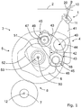
- Fig. 1 schematically shows in a side view a sley 1 of a weaving machine.
- a reed 10 is mounted to the sley 1 for beating-up weft threads against a fell line 20 of a fabric 2 in a manner generally known.
- the sley 1 with the reed 10 is moved in an oscillating manner to and fro by means of a sley drive system 3.
- the sley drive system 3 shown in Fig. 1 comprises a sley lever unit 4 arranged to rotate to and fro about a sley lever axis 40 and a sley drive unit 5 for driving the sley lever unit 4.
- the sley drive unit 5 comprises two conjugated cams 51, 52.
- the cams 51, 52 are fixedly mounted on a common cam shaft 53 to rotate conjointly about a central axis 50, which in this example is also the axis of rotation of the cam shaft 53.
- the cams 51, 52 are arranged offset to one another in axial direction, so that the cam 51 is hidden by the other cam 52 as indicated with broken lines in Fig. 1 .
- the cam shaft 53 is mounted by means of a bearing (not shown in Fig. 1 ) on a support element 6 of the weaving machine, for example a support element 6 that is part of the housing 30 (shown in figure 10 ).
- the sley lever unit 4 shown in Fig. 1 comprises a fork element 42 having two support arms 43, which are fixedly mounted on a sley shaft 44 to pivot conjointly about the sley lever axis 40, this is the axis of rotation of the sley shaft 44.
- the sley shaft 44 is mounted in the sley lever unit 4.
- the sley shaft 44 is part of the sley 1.
- a sley beam 11 onto which the reed 10 is mounted is fixed via sley legs 41 onto the sley shaft 44 of the sley 1.
- each support arm 43 functions as a cam follower 45, each of the cam followers 45 being associated to and drivingly coupled with one of the two conjugated cams 51, 52.
- the cam followers 45 each comprise a roller 46, 47 rolling on a cam surface of the associated cam 51, 52.
- Each roller 46, 47 is rotatably mounted by a bearing 48, 49 on the respective support arm 43.
- the cams 51, 52 are driven by a sley drive motor 7 (shown schematically in figure 1 ), which is distinct from other drive motors (not shown) of the weaving machine.
- a gearing unit 8 is provided between the sley drive motor 7 and the cam shaft 53, wherein a motor shaft 12 of the sley drive motor 7 rotates at a higher speed than the cam shaft 53.
- cam followers 45 in the embodiment shown are arranged below a fabric 2 allowing for a compact structure.
- the cam profiles of the two conjugated cams 51, 52 are chosen so that two working cycles of the sley lever unit 4, this means two beat-up strokes of the reed 10 are carried out during one revolution of the two conjugated cams 51, 52.
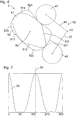
- Fig. 2 schematically illustrates two conjugated cams 51, 52, the fork element 42 with the support arms 43 and the rollers 46, 47.
- the cam profiles of both cams 51, 52 are central symmetrical about the central axis 50, this is the axis of rotation of the cams 51, 52.
- the sley drive system 3 of Fig. 2 imposes a movement course 31 on the sley shaft 44 as shown in Fig. 3 , which is symmetrical with respect to a plane 35.
- a pivot movement of the fork element 42 and the sley lever unit 4 (shown in Fig. 1 ) is independent of the sense of rotation of the two cams 51, 52.
- a fork element 42 is shown in one of its extreme positions.
- a further rotation of the cams 51, 52 regardless the sense of rotation of the cams 51, 52, will cause the fork element 42 to pivot in clockwise direction, this means the reed 10 shown in Fig. 1 will move away from the fell line 20 until reaching its rearward end position. The rearward end position will be reached after the cams 51, 52 have rotated about 90°. Thereafter, the rotation of the cams 51, 52 will cause the fork element 42 to rotate in counterclockwise direction and the reed 10 will move towards the fell line 20 for beating up a weft thread.
- the force required for driving the cam followers is equal to a pressure force multiplied by the cosinus of the pressure angle.
- the pressure angle A, B is the angle between the speed vector of the center of a roller 46, 47, which is perpendicular to its support arm 43, and the force vector between the respective roller 46, 47 and the associated cam 51, 52, as shown in Fig. 2 .
- the two support arms 43 have the same length, wherein the length of the support arms 43 is maximized while considering space limitations. In other embodiments, the support arms 43 differ in length.
- Fig. 4 schematically illustrates two conjugated cams 51, 52, a fork element 42 with the support arms 43 and rollers 46, 47 of an alternative sley drive system 3.
- the cam profiles of both cams 51, 52 impose a movement course 32 to the sley shaft 44, as shown in Fig. 5 , that is not symmetrical with respect to a plane 35.
- a pivot movement of the fork element 42 and the sley lever unit 4 shown in Fig. 1
- the movement of the sley 1 and the reed 10 differ for the backward and the forward movement.
- the profile sections 511, 524 and 513, 522 will determine the movement of the sley 1 and the reed 10 away from the fell line 20, whereas the profile sections 512, 521 and 514, 523 will determine the movement of the sley 1 and the reed 10 towards the fell line 20.
- the profile sections 512, 521 and 514, 523 will determine the movement of the sley 1 and the reed 10 away from the fell line 20, whereas the profile sections 511, 524 and 513, 522 will determine the movement of the sley 1 and the reed 10 towards the fell line 20.
- the cams 51, 52 possess central symmetry, and the opposing profile sections 511 and 513, the opposing profile sections 512 and 514, the opposing profile sections 521 and 523, and the opposing profile sections 522 and 524, respectively, are equal to each other.
- cam profiles according to Fig. 4 are chosen for example to move the reed 10 away from the fell line 20 at high speed for allowing the insertion of a weft thread to start earlier in the weaving cycle of an airjet weaving machine.
- Fig. 6 schematically illustrates two conjugated cams 51, 52, a fork element 42 with the support arms 43 and rollers 46, 47 of an alternative sley drive system 3, wherein the cam profiles of both cams 51, 52 impose with respect to a plane 35 a symmetrical movement course 33 on the sley shaft 44, as shown in Fig. 7 .
- Fig. 8 schematically illustrates two conjugated cams 51, 52, a fork element 42 with support arms 43 and rollers 46, 47 of another alternative sley drive system 3, wherein the cam profiles of both cams 51, 52 impose with respect to a plane 35 a symmetrical movement course 34 on the sley shaft 44, as shown in Fig. 9 .
- Fig. 10 shows schematically a front view of a device 9 comprising three sley drive systems 3 for driving conjointly a sley 1, which are arranged coaxially with respect to a sley lever axis 40 and offset in axial direction.
- each sley drive system 3 comprises a sley lever unit 4 and a sley drive unit 5, which are housed in a housing 30 and therefore not visible in Fig. 10 .
- the sley lever units 4 have a common sley shaft 44, which is driven to pivot to and fro, which is part of the sley 1.
- the sley beam 11 of the sley 1 is mounted on the sley shaft 44 via several sley legs 41, which are distributedly arranged along the sley shaft 44.
- the reed 10 is mounted on the sley beam 11.
- each of the sley drive systems 3 is assigned to a common sley drive motor 7. In other embodiments, each sley drive system 3 uses an individual drive motor.
- Figs. 2 , 4 , 6 and 8 illustrate that numerous embodiments are conceivable for providing two conjugated cams 51, 52.
- profiles are chosen so that the center of gravity of the two conjugated cams 51, 52 coincides at least essentially with the central axis 50, this is the axis of rotation of the cams 51, 52.
- the diameter of the rollers 46, 47 is maximized while ensuring a rolling on the associated cam surface and considering space limitations of the housing 30.
- the sley drive system, the device and the weaving machine according to the invention are not limited to the embodiments described by way of example and shown in the drawings.
- the sley drive system, the device and the weaving machine can also be carried out within the claims according to variant embodiments, shapes and dimensions, and combinations of the described and shown embodiments that fall under the claims are also possible;
Landscapes
- Engineering & Computer Science (AREA)
- Textile Engineering (AREA)
- Looms (AREA)
Claims (10)
- Ladenantriebssystem zum oszillierenden Antreiben einer Weblade (1), wobei das Ladenantriebssystem (3) eine Ladenhebeleinheit (4), die zum Oszillieren um eine Ladenhebelachse (40) angeordnet ist, und eine Ladenantriebseinheit (5) zum Antreiben der Ladenhebeleinheit (4) umfasst, wobei die Ladenantriebseinheit (5) zwei konjugierte Nocken (51, 52) umfasst und die Ladenhebeleinheit (4) zwei Nockenfolger (45) umfasst, wobei jeder Nockenfolger (45) einem der zwei konjugierten Nocken (51, 52) zugeordnet und antriebsmässig damit gekoppelt ist, dadurch gekennzeichnet, dass die Nockenscheiben der zwei konjugierten Nocken (51, 52) so gewählt sind, dass zwei Arbeitszyklen der Ladenhebeleinheit (4) während einer Umdrehung der zwei konjugierten Nocken (51, 52) ausgeführt werden.
- Ladenantriebssystem nach Anspruch 1, dadurch gekennzeichnet, dass jeder Nockenfolger (45) eine auf einer zugeordneten Nockenfläche abrollende Rolle (46, 47) umfasst, welche Rolle (46, 47) über ein Lager (48, 49) an einem Tragarm (43) der Ladenhebeleinheit (4) drehbar montiert ist.
- Ladenantriebssystem nach Anspruch 1 oder 2, dadurch gekennzeichnet, dass die zwei konjugierten Nocken (51, 52) fest auf einer Nockenwelle (53) montiert sind, wobei zwischen einem Ladenantriebsmotor (7) und der Nockenwelle (53) eine Getriebeeinheit (8) vorgesehen ist.
- Ladenantriebssystem nach einem der Ansprüche 1 bis 3, dadurch gekennzeichnet, dass das Ladenantriebssystem (3) einen Ladenantriebsmotor (7) umfasst, der sich von den anderen Antriebsmotoren der Webmaschine unterscheidet.
- Ladenantriebssystem nach einem der Ansprüche 1 bis 4, dadurch gekennzeichnet, dass die Nockenfolger (45) auf der Ladenhebeleinheit (4) vorgesehen sind, umfassend ein Gabelelement (42) mit zwei Tragarmen (43), die zum gemeinsamen Drehen um die Ladenhebelachse (40) angeordnet sind.
- Ladenantriebssystem nach einem der Ansprüche 1 bis 5, dadurch gekennzeichnet, dass die Nockenscheiben der zwei konjugierten Nocken (51, 52) jeweils zentrale Symmetrie besitzen.
- Ladenantriebssystem nach einem der Ansprüche 1 bis 6, dadurch gekennzeichnet, dass die Nockenscheiben so gewählt sind, dass der Schwerpunkt der zwei konjugierten Nocken (51, 52) mindestens im Wesentlichen mit der Mittelachse (50) der Nockenwelle (53) zusammenfällt.
- Vorrichtung umfassend mindestens zwei Ladenantriebssysteme (3) nach einem der Ansprüche 1 bis 7, jeweils mit zwei konjugierten Nocken (51, 52) und zwei Nockenfolgern (45), wobei die mindestens zwei Ladenantriebssysteme (3) koaxial und versetzt angeordnet sind.
- Webmaschine umfassend mindestens ein Ladenantriebssystem (3) nach einem der Ansprüche 1 bis 7 mit einer Ladenhebeleinheit (4) und einer Ladenantriebseinheit (5) zum Antreiben der Ladenhebeleinheit (4), wobei die Ladenantriebseinheit (5) zwei konjugierte Nocken (51, 52) umfasst und die Ladenhebeleinheit (4) zwei Nockenfolger (45) umfasst.
- Webmaschine nach Anspruch 9, wobei die Nockenfolger (45) der Ladenantriebseinheit (5) im Gebrauch unterhalb eines Gewebes (2) angeordnet sind.
Applications Claiming Priority (2)
| Application Number | Priority Date | Filing Date | Title |
|---|---|---|---|
| BE2015/0052A BE1022756B1 (nl) | 2015-01-19 | 2015-01-19 | Ladeaandrijfsysteem voor een weefmachine. |
| PCT/EP2015/076992 WO2016116193A1 (en) | 2015-01-19 | 2015-11-18 | Sley drive system for a weaving machine |
Publications (2)
| Publication Number | Publication Date |
|---|---|
| EP3247829A1 EP3247829A1 (de) | 2017-11-29 |
| EP3247829B1 true EP3247829B1 (de) | 2020-01-01 |
Family
ID=53189525
Family Applications (1)
| Application Number | Title | Priority Date | Filing Date |
|---|---|---|---|
| EP15798028.5A Active EP3247829B1 (de) | 2015-01-19 | 2015-11-18 | Ladeantriebssystem für eine webmaschine |
Country Status (3)
| Country | Link |
|---|---|
| EP (1) | EP3247829B1 (de) |
| BE (1) | BE1022756B1 (de) |
| WO (1) | WO2016116193A1 (de) |
Families Citing this family (2)
| Publication number | Priority date | Publication date | Assignee | Title |
|---|---|---|---|---|
| CN109735999B (zh) * | 2019-01-23 | 2024-01-05 | 天津工业大学 | 一种用于立体织物的平行打纬装置 |
| DE102022210435B4 (de) * | 2022-09-30 | 2025-09-11 | Volkswagen Aktiengesellschaft | Elastokalorische Wärmepumpe und Kraftfahrzeug mit elastokalorischer Wärmepumpe |
Family Cites Families (3)
| Publication number | Priority date | Publication date | Assignee | Title |
|---|---|---|---|---|
| FR1110124A (fr) * | 1953-10-17 | 1956-02-06 | Perfectionnements aux métiers mécaniques | |
| CH594090A5 (de) * | 1975-06-10 | 1977-12-30 | Sulzer Ag | |
| BE1016493A3 (nl) * | 2005-04-13 | 2006-12-05 | Wiele Michel Van De Nv | Inrichting voor het moduleren van een eerste roterende beweging van een inkomende as naar een tweede, verschillend van de eerste, roterende beweging van een uitgaande as bij textielmachines. |
-
2015
- 2015-01-19 BE BE2015/0052A patent/BE1022756B1/nl not_active IP Right Cessation
- 2015-11-18 EP EP15798028.5A patent/EP3247829B1/de active Active
- 2015-11-18 WO PCT/EP2015/076992 patent/WO2016116193A1/en not_active Ceased
Non-Patent Citations (1)
| Title |
|---|
| None * |
Also Published As
| Publication number | Publication date |
|---|---|
| BE1022756B1 (nl) | 2016-08-30 |
| BE1022756A1 (nl) | 2016-08-30 |
| WO2016116193A1 (en) | 2016-07-28 |
| EP3247829A1 (de) | 2017-11-29 |
Similar Documents
| Publication | Publication Date | Title |
|---|---|---|
| JP2004514804A (ja) | 織機及び開口機械のための駆動設備 | |
| CZ202798A3 (cs) | Zařízení pro tvoření perlinkového okraje, zejména pro tkací stroj | |
| EP3247829A1 (de) | Ladeantriebssystem für eine webmaschine | |
| CN1847700B (zh) | 把输入轴第一旋转运动调节成输出轴第二旋转运动的装置 | |
| US3603351A (en) | Dobby for looms | |
| CN101275324B (zh) | 用于织机偏心设备的凸轮 | |
| CN103320946A (zh) | 数控毛巾机活筘机构 | |
| CN101525802A (zh) | 新型直轴打纬机构 | |
| US3335760A (en) | Gripper looms | |
| US3955603A (en) | Looms provided with means for making movement thereof uniform | |
| RU2091523C1 (ru) | Устройство для выравнивания мощности в батанном механизме ткацкого станка и ткацкий станок, содержащий это устройство | |
| JP6751413B2 (ja) | 織機における緯糸搬送グリッパーの往復運動を制御する機構 | |
| US2119413A (en) | Loom governor | |
| US4036265A (en) | Device for supporting the slay drive of a loom | |
| US3858621A (en) | Mechanism for actuating the slay of a weaving loom | |
| EP1544509B1 (de) | Antriebvorrichtung | |
| CN2863828Y (zh) | 织机织物起毛装置 | |
| CN201377027Y (zh) | 新型直轴打纬机构 | |
| US3866482A (en) | Drive system for reed roller of weaving machine | |
| CN215328597U (zh) | 一种纺织机打纬装置 | |
| US2635646A (en) | Letoff mechanism for looms | |
| US812485A (en) | Picking mechanism for looms. | |
| EP1710333A2 (de) | Antriebsvorrichtung für die Bewegungsteile für die Plüschhenkelbildung in einer Frottierwebmaschine mit bewegbarem Tuch | |
| CN108823762A (zh) | 一种布动起毛装置及布动起毛装置动力机构 | |
| CN102191605A (zh) | 旋转多臂机和装配有该多臂机的织机 |
Legal Events
| Date | Code | Title | Description |
|---|---|---|---|
| STAA | Information on the status of an ep patent application or granted ep patent |
Free format text: STATUS: THE INTERNATIONAL PUBLICATION HAS BEEN MADE |
|
| PUAI | Public reference made under article 153(3) epc to a published international application that has entered the european phase |
Free format text: ORIGINAL CODE: 0009012 |
|
| STAA | Information on the status of an ep patent application or granted ep patent |
Free format text: STATUS: REQUEST FOR EXAMINATION WAS MADE |
|
| 17P | Request for examination filed |
Effective date: 20170623 |
|
| AK | Designated contracting states |
Kind code of ref document: A1 Designated state(s): AL AT BE BG CH CY CZ DE DK EE ES FI FR GB GR HR HU IE IS IT LI LT LU LV MC MK MT NL NO PL PT RO RS SE SI SK SM TR |
|
| AX | Request for extension of the european patent |
Extension state: BA ME |
|
| DAV | Request for validation of the european patent (deleted) | ||
| DAX | Request for extension of the european patent (deleted) | ||
| GRAP | Despatch of communication of intention to grant a patent |
Free format text: ORIGINAL CODE: EPIDOSNIGR1 |
|
| STAA | Information on the status of an ep patent application or granted ep patent |
Free format text: STATUS: GRANT OF PATENT IS INTENDED |
|
| INTG | Intention to grant announced |
Effective date: 20190625 |
|
| GRAS | Grant fee paid |
Free format text: ORIGINAL CODE: EPIDOSNIGR3 |
|
| GRAJ | Information related to disapproval of communication of intention to grant by the applicant or resumption of examination proceedings by the epo deleted |
Free format text: ORIGINAL CODE: EPIDOSDIGR1 |
|
| GRAL | Information related to payment of fee for publishing/printing deleted |
Free format text: ORIGINAL CODE: EPIDOSDIGR3 |
|
| STAA | Information on the status of an ep patent application or granted ep patent |
Free format text: STATUS: REQUEST FOR EXAMINATION WAS MADE |
|
| GRAR | Information related to intention to grant a patent recorded |
Free format text: ORIGINAL CODE: EPIDOSNIGR71 |
|
| STAA | Information on the status of an ep patent application or granted ep patent |
Free format text: STATUS: GRANT OF PATENT IS INTENDED |
|
| INTC | Intention to grant announced (deleted) | ||
| INTG | Intention to grant announced |
Effective date: 20191023 |
|
| GRAA | (expected) grant |
Free format text: ORIGINAL CODE: 0009210 |
|
| STAA | Information on the status of an ep patent application or granted ep patent |
Free format text: STATUS: THE PATENT HAS BEEN GRANTED |
|
| AK | Designated contracting states |
Kind code of ref document: B1 Designated state(s): AL AT BE BG CH CY CZ DE DK EE ES FI FR GB GR HR HU IE IS IT LI LT LU LV MC MK MT NL NO PL PT RO RS SE SI SK SM TR |
|
| REG | Reference to a national code |
Ref country code: GB Ref legal event code: FG4D |
|
| REG | Reference to a national code |
Ref country code: CH Ref legal event code: EP Ref country code: AT Ref legal event code: REF Ref document number: 1219887 Country of ref document: AT Kind code of ref document: T Effective date: 20200115 |
|
| REG | Reference to a national code |
Ref country code: IE Ref legal event code: FG4D |
|
| REG | Reference to a national code |
Ref country code: DE Ref legal event code: R096 Ref document number: 602015044795 Country of ref document: DE |
|
| REG | Reference to a national code |
Ref country code: NL Ref legal event code: MP Effective date: 20200101 |
|
| REG | Reference to a national code |
Ref country code: LT Ref legal event code: MG4D |
|
| PG25 | Lapsed in a contracting state [announced via postgrant information from national office to epo] |
Ref country code: NL Free format text: LAPSE BECAUSE OF FAILURE TO SUBMIT A TRANSLATION OF THE DESCRIPTION OR TO PAY THE FEE WITHIN THE PRESCRIBED TIME-LIMIT Effective date: 20200101 Ref country code: LT Free format text: LAPSE BECAUSE OF FAILURE TO SUBMIT A TRANSLATION OF THE DESCRIPTION OR TO PAY THE FEE WITHIN THE PRESCRIBED TIME-LIMIT Effective date: 20200101 Ref country code: CZ Free format text: LAPSE BECAUSE OF FAILURE TO SUBMIT A TRANSLATION OF THE DESCRIPTION OR TO PAY THE FEE WITHIN THE PRESCRIBED TIME-LIMIT Effective date: 20200101 Ref country code: PT Free format text: LAPSE BECAUSE OF FAILURE TO SUBMIT A TRANSLATION OF THE DESCRIPTION OR TO PAY THE FEE WITHIN THE PRESCRIBED TIME-LIMIT Effective date: 20200527 Ref country code: NO Free format text: LAPSE BECAUSE OF FAILURE TO SUBMIT A TRANSLATION OF THE DESCRIPTION OR TO PAY THE FEE WITHIN THE PRESCRIBED TIME-LIMIT Effective date: 20200401 Ref country code: FI Free format text: LAPSE BECAUSE OF FAILURE TO SUBMIT A TRANSLATION OF THE DESCRIPTION OR TO PAY THE FEE WITHIN THE PRESCRIBED TIME-LIMIT Effective date: 20200101 Ref country code: RS Free format text: LAPSE BECAUSE OF FAILURE TO SUBMIT A TRANSLATION OF THE DESCRIPTION OR TO PAY THE FEE WITHIN THE PRESCRIBED TIME-LIMIT Effective date: 20200101 |
|
| PG25 | Lapsed in a contracting state [announced via postgrant information from national office to epo] |
Ref country code: SE Free format text: LAPSE BECAUSE OF FAILURE TO SUBMIT A TRANSLATION OF THE DESCRIPTION OR TO PAY THE FEE WITHIN THE PRESCRIBED TIME-LIMIT Effective date: 20200101 Ref country code: LV Free format text: LAPSE BECAUSE OF FAILURE TO SUBMIT A TRANSLATION OF THE DESCRIPTION OR TO PAY THE FEE WITHIN THE PRESCRIBED TIME-LIMIT Effective date: 20200101 Ref country code: HR Free format text: LAPSE BECAUSE OF FAILURE TO SUBMIT A TRANSLATION OF THE DESCRIPTION OR TO PAY THE FEE WITHIN THE PRESCRIBED TIME-LIMIT Effective date: 20200101 Ref country code: GR Free format text: LAPSE BECAUSE OF FAILURE TO SUBMIT A TRANSLATION OF THE DESCRIPTION OR TO PAY THE FEE WITHIN THE PRESCRIBED TIME-LIMIT Effective date: 20200402 Ref country code: IS Free format text: LAPSE BECAUSE OF FAILURE TO SUBMIT A TRANSLATION OF THE DESCRIPTION OR TO PAY THE FEE WITHIN THE PRESCRIBED TIME-LIMIT Effective date: 20200501 Ref country code: BG Free format text: LAPSE BECAUSE OF FAILURE TO SUBMIT A TRANSLATION OF THE DESCRIPTION OR TO PAY THE FEE WITHIN THE PRESCRIBED TIME-LIMIT Effective date: 20200401 |
|
| REG | Reference to a national code |
Ref country code: DE Ref legal event code: R097 Ref document number: 602015044795 Country of ref document: DE |
|
| PG25 | Lapsed in a contracting state [announced via postgrant information from national office to epo] |
Ref country code: SM Free format text: LAPSE BECAUSE OF FAILURE TO SUBMIT A TRANSLATION OF THE DESCRIPTION OR TO PAY THE FEE WITHIN THE PRESCRIBED TIME-LIMIT Effective date: 20200101 Ref country code: EE Free format text: LAPSE BECAUSE OF FAILURE TO SUBMIT A TRANSLATION OF THE DESCRIPTION OR TO PAY THE FEE WITHIN THE PRESCRIBED TIME-LIMIT Effective date: 20200101 Ref country code: RO Free format text: LAPSE BECAUSE OF FAILURE TO SUBMIT A TRANSLATION OF THE DESCRIPTION OR TO PAY THE FEE WITHIN THE PRESCRIBED TIME-LIMIT Effective date: 20200101 Ref country code: ES Free format text: LAPSE BECAUSE OF FAILURE TO SUBMIT A TRANSLATION OF THE DESCRIPTION OR TO PAY THE FEE WITHIN THE PRESCRIBED TIME-LIMIT Effective date: 20200101 Ref country code: DK Free format text: LAPSE BECAUSE OF FAILURE TO SUBMIT A TRANSLATION OF THE DESCRIPTION OR TO PAY THE FEE WITHIN THE PRESCRIBED TIME-LIMIT Effective date: 20200101 Ref country code: SK Free format text: LAPSE BECAUSE OF FAILURE TO SUBMIT A TRANSLATION OF THE DESCRIPTION OR TO PAY THE FEE WITHIN THE PRESCRIBED TIME-LIMIT Effective date: 20200101 |
|
| PLBE | No opposition filed within time limit |
Free format text: ORIGINAL CODE: 0009261 |
|
| STAA | Information on the status of an ep patent application or granted ep patent |
Free format text: STATUS: NO OPPOSITION FILED WITHIN TIME LIMIT |
|
| REG | Reference to a national code |
Ref country code: AT Ref legal event code: MK05 Ref document number: 1219887 Country of ref document: AT Kind code of ref document: T Effective date: 20200101 |
|
| 26N | No opposition filed |
Effective date: 20201002 |
|
| PG25 | Lapsed in a contracting state [announced via postgrant information from national office to epo] |
Ref country code: AT Free format text: LAPSE BECAUSE OF FAILURE TO SUBMIT A TRANSLATION OF THE DESCRIPTION OR TO PAY THE FEE WITHIN THE PRESCRIBED TIME-LIMIT Effective date: 20200101 |
|
| PG25 | Lapsed in a contracting state [announced via postgrant information from national office to epo] |
Ref country code: PL Free format text: LAPSE BECAUSE OF FAILURE TO SUBMIT A TRANSLATION OF THE DESCRIPTION OR TO PAY THE FEE WITHIN THE PRESCRIBED TIME-LIMIT Effective date: 20200101 Ref country code: SI Free format text: LAPSE BECAUSE OF FAILURE TO SUBMIT A TRANSLATION OF THE DESCRIPTION OR TO PAY THE FEE WITHIN THE PRESCRIBED TIME-LIMIT Effective date: 20200101 |
|
| PG25 | Lapsed in a contracting state [announced via postgrant information from national office to epo] |
Ref country code: MC Free format text: LAPSE BECAUSE OF FAILURE TO SUBMIT A TRANSLATION OF THE DESCRIPTION OR TO PAY THE FEE WITHIN THE PRESCRIBED TIME-LIMIT Effective date: 20200101 |
|
| REG | Reference to a national code |
Ref country code: CH Ref legal event code: PL |
|
| GBPC | Gb: european patent ceased through non-payment of renewal fee |
Effective date: 20201118 |
|
| PG25 | Lapsed in a contracting state [announced via postgrant information from national office to epo] |
Ref country code: LU Free format text: LAPSE BECAUSE OF NON-PAYMENT OF DUE FEES Effective date: 20201118 |
|
| PG25 | Lapsed in a contracting state [announced via postgrant information from national office to epo] |
Ref country code: CH Free format text: LAPSE BECAUSE OF NON-PAYMENT OF DUE FEES Effective date: 20201130 Ref country code: LI Free format text: LAPSE BECAUSE OF NON-PAYMENT OF DUE FEES Effective date: 20201130 |
|
| PG25 | Lapsed in a contracting state [announced via postgrant information from national office to epo] |
Ref country code: FR Free format text: LAPSE BECAUSE OF NON-PAYMENT OF DUE FEES Effective date: 20201130 Ref country code: IE Free format text: LAPSE BECAUSE OF NON-PAYMENT OF DUE FEES Effective date: 20201118 |
|
| PG25 | Lapsed in a contracting state [announced via postgrant information from national office to epo] |
Ref country code: GB Free format text: LAPSE BECAUSE OF NON-PAYMENT OF DUE FEES Effective date: 20201118 |
|
| PG25 | Lapsed in a contracting state [announced via postgrant information from national office to epo] |
Ref country code: MT Free format text: LAPSE BECAUSE OF FAILURE TO SUBMIT A TRANSLATION OF THE DESCRIPTION OR TO PAY THE FEE WITHIN THE PRESCRIBED TIME-LIMIT Effective date: 20200101 Ref country code: CY Free format text: LAPSE BECAUSE OF FAILURE TO SUBMIT A TRANSLATION OF THE DESCRIPTION OR TO PAY THE FEE WITHIN THE PRESCRIBED TIME-LIMIT Effective date: 20200101 |
|
| PG25 | Lapsed in a contracting state [announced via postgrant information from national office to epo] |
Ref country code: MK Free format text: LAPSE BECAUSE OF FAILURE TO SUBMIT A TRANSLATION OF THE DESCRIPTION OR TO PAY THE FEE WITHIN THE PRESCRIBED TIME-LIMIT Effective date: 20200101 Ref country code: AL Free format text: LAPSE BECAUSE OF FAILURE TO SUBMIT A TRANSLATION OF THE DESCRIPTION OR TO PAY THE FEE WITHIN THE PRESCRIBED TIME-LIMIT Effective date: 20200101 |
|
| P01 | Opt-out of the competence of the unified patent court (upc) registered |
Effective date: 20230519 |
|
| PGFP | Annual fee paid to national office [announced via postgrant information from national office to epo] |
Ref country code: DE Payment date: 20251126 Year of fee payment: 11 |
|
| PGFP | Annual fee paid to national office [announced via postgrant information from national office to epo] |
Ref country code: IT Payment date: 20251128 Year of fee payment: 11 |
|
| PGFP | Annual fee paid to national office [announced via postgrant information from national office to epo] |
Ref country code: TR Payment date: 20251113 Year of fee payment: 11 Ref country code: BE Payment date: 20251002 Year of fee payment: 11 |