EP3247882B1 - Unterirdische lüftungsvorrichtung und verfahren - Google Patents
Unterirdische lüftungsvorrichtung und verfahren Download PDFInfo
- Publication number
- EP3247882B1 EP3247882B1 EP16739689.4A EP16739689A EP3247882B1 EP 3247882 B1 EP3247882 B1 EP 3247882B1 EP 16739689 A EP16739689 A EP 16739689A EP 3247882 B1 EP3247882 B1 EP 3247882B1
- Authority
- EP
- European Patent Office
- Prior art keywords
- semi
- tubular
- section
- sections
- engagement formation
- Prior art date
- Legal status (The legal status is an assumption and is not a legal conclusion. Google has not performed a legal analysis and makes no representation as to the accuracy of the status listed.)
- Active
Links
Images



Classifications
-
- E—FIXED CONSTRUCTIONS
- E21—EARTH OR ROCK DRILLING; MINING
- E21F—SAFETY DEVICES, TRANSPORT, FILLING-UP, RESCUE, VENTILATION, OR DRAINING IN OR OF MINES OR TUNNELS
- E21F1/00—Ventilation of mines or tunnels; Distribution of ventilating currents
- E21F1/04—Air ducts
- E21F1/06—Duct connections
-
- E—FIXED CONSTRUCTIONS
- E21—EARTH OR ROCK DRILLING; MINING
- E21F—SAFETY DEVICES, TRANSPORT, FILLING-UP, RESCUE, VENTILATION, OR DRAINING IN OR OF MINES OR TUNNELS
- E21F1/00—Ventilation of mines or tunnels; Distribution of ventilating currents
- E21F1/006—Ventilation at the working face of galleries or tunnels
-
- F—MECHANICAL ENGINEERING; LIGHTING; HEATING; WEAPONS; BLASTING
- F16—ENGINEERING ELEMENTS AND UNITS; GENERAL MEASURES FOR PRODUCING AND MAINTAINING EFFECTIVE FUNCTIONING OF MACHINES OR INSTALLATIONS; THERMAL INSULATION IN GENERAL
- F16L—PIPES; JOINTS OR FITTINGS FOR PIPES; SUPPORTS FOR PIPES, CABLES OR PROTECTIVE TUBING; MEANS FOR THERMAL INSULATION IN GENERAL
- F16L9/00—Rigid pipes
- F16L9/22—Pipes composed of a plurality of segments
-
- E—FIXED CONSTRUCTIONS
- E21—EARTH OR ROCK DRILLING; MINING
- E21F—SAFETY DEVICES, TRANSPORT, FILLING-UP, RESCUE, VENTILATION, OR DRAINING IN OR OF MINES OR TUNNELS
- E21F1/00—Ventilation of mines or tunnels; Distribution of ventilating currents
- E21F1/04—Air ducts
-
- F—MECHANICAL ENGINEERING; LIGHTING; HEATING; WEAPONS; BLASTING
- F16—ENGINEERING ELEMENTS AND UNITS; GENERAL MEASURES FOR PRODUCING AND MAINTAINING EFFECTIVE FUNCTIONING OF MACHINES OR INSTALLATIONS; THERMAL INSULATION IN GENERAL
- F16L—PIPES; JOINTS OR FITTINGS FOR PIPES; SUPPORTS FOR PIPES, CABLES OR PROTECTIVE TUBING; MEANS FOR THERMAL INSULATION IN GENERAL
- F16L17/00—Joints with packing adapted to sealing by fluid pressure
- F16L17/02—Joints with packing adapted to sealing by fluid pressure with sealing rings arranged between outer surface of pipe and inner surface of sleeve or socket
- F16L17/04—Joints with packing adapted to sealing by fluid pressure with sealing rings arranged between outer surface of pipe and inner surface of sleeve or socket with longitudinally split or divided sleeve
-
- F—MECHANICAL ENGINEERING; LIGHTING; HEATING; WEAPONS; BLASTING
- F16—ENGINEERING ELEMENTS AND UNITS; GENERAL MEASURES FOR PRODUCING AND MAINTAINING EFFECTIVE FUNCTIONING OF MACHINES OR INSTALLATIONS; THERMAL INSULATION IN GENERAL
- F16L—PIPES; JOINTS OR FITTINGS FOR PIPES; SUPPORTS FOR PIPES, CABLES OR PROTECTIVE TUBING; MEANS FOR THERMAL INSULATION IN GENERAL
- F16L21/00—Joints with sleeve or socket
- F16L21/06—Joints with sleeve or socket with a divided sleeve or ring clamping around the pipe ends
-
- Y—GENERAL TAGGING OF NEW TECHNOLOGICAL DEVELOPMENTS; GENERAL TAGGING OF CROSS-SECTIONAL TECHNOLOGIES SPANNING OVER SEVERAL SECTIONS OF THE IPC; TECHNICAL SUBJECTS COVERED BY FORMER USPC CROSS-REFERENCE ART COLLECTIONS [XRACs] AND DIGESTS
- Y10—TECHNICAL SUBJECTS COVERED BY FORMER USPC
- Y10T—TECHNICAL SUBJECTS COVERED BY FORMER US CLASSIFICATION
- Y10T29/00—Metal working
- Y10T29/49—Method of mechanical manufacture
- Y10T29/49826—Assembling or joining
Definitions
- the present disclosure relates to an underground ventilation apparatus and method.
- the present invention relates to a ventilation apparatus and method for use in mining applications, and in particular, in coal mining applications.
- Coal mining is generally performed utilising either an open cut or alternatively an underground mining method.
- coal mining is conducted underground, it is essential that there is sufficient ventilation within the mine for workers. This requires the provision of fresh air from outside, in addition to the removal of potentially harmful waste gasses generated within the mine.
- Ventilating remote locations within an underground mine can be particularly difficult to achieve. It is necessary to install and maintain a ventilation circuit including an intake and a separate return airway to the innermost location to be ventilated. Ventilation tubing is typically installed as the mine is cut by a continuous miner, after the roadway has been excavated and the roof supported, prior to further advancement of the continuous miner.
- the final portion of the roadway in front of the continuous miner defines an air flow impasse, which creates a stagnant area, having limited air flow and ventilation. This occurs because the air flow circuit is closed in this region of the mine. This makes it difficult to ventilate at or near the cutting face, where the continuous miner, and any workers operating the continuous miner, are located.
- the cutting face is generally ventilated using an auxiliary fan which has ventilation tubes connected to it.
- the ventilation tubes run from the fan (which is positioned in the return airway) and the tubes are suspended from the roof of the mine, and extend all the way to the cutting face.
- the fan is used to draw air away from the cutting face, which in turn creates a low air pressure at the cutting face. This results in fresh air from the fresh air supply line being drawn toward the face and also displacing airborne dust and gases away from the area.
- the continuous miner As the continuous miner cuts the coal, the cutting face progresses forward and the roof of the roadway is supported using bolts or other support techniques.
- the continuous miner includes a flexible trunk that is connected to the end of the ventilation tube which is located closest to the cutting face.
- the flexible trunk is approximately 8 - 10 metres long. Accordingly, after 8 - 10 metres of mining, the process of hanging another two ventilation tubes is conducted.
- the process requires that the diesel vehicle drives behind the continuous miner, two workers get into the man basket and are lifted up to the height of the flexible trunk. The workers then pull the rest of the flexible trunk out of the existing vent tubes and proceed to hang the new ventilation tubes that have been supplied by the basket. After this process is completed, the workers reinstall the flexible trunk to the end of the new ventilation tubes to reinstate ventilation to the cutting face.
- Existing ventilation tubes are typically stored within the mine prior to and after use, typically in a cut-through formation, where they are stacked side by side and on top of each other. The large volume of space required prevents the cut-through (or other storage location within the mine) from being utilised for storing other mining equipment.
- the existing ventilation tubes are heavy, which creates various manual handling risks when the tubes are being installed, decommissioned or otherwise moved.
- a further problem with the existing ventilation system described above concerns downtime in production on account of the time required to install the ventilation tubes which can take from 25 - 35 minutes to complete and on average needs to be done three times per shift.
- a further disadvantage with existing underground ventilation systems concerns the retrieval of the vent tubes.
- This process typically requires six men and two Jug-A-O machines to reclaim vent tubes for a single panel advance (the block of coal being mined). This process on average usually takes half a shift, and may be necessary once a month. Three men are occupied by the Jug-A-O with the man basket being used to remove the tubes from the roof and drop them down to the floor where another worker loads the tubes that have been dropped onto a second Jug-A-O that is used to take the tubes to a storage area. The operator of the Jug-A-O that is taking the tubes to the storage area is then met by another worker that is waiting to stack the tubes for storage. Disadvantageously, this process is labour intensive, and requires significant amounts of manual handling and lifting of heavy vent tubes.
- each vent tube must be manually handled six times from hanging on the roof to the placement in the storage area. Given that approximately 100 vent tubes typically need to be moved for a single panel advance, the amount of man handling is significant.
- a patent related document includes US 1, 025, 186 A which discloses the preamble of claim 1.
- the present invention provides a ventilation apparatus according to claim 1 and comprising :
- Each of the first and second semi-tubular sections includes a third engagement formation and a corresponding fourth engagement formation.
- the third engagement formation includes a longitudinally extending rib
- the fourth engagement formation includes a corresponding longitudinally extending groove
- the groove preferably includes at least one outwardly tapering lip, the lip providing a lateral guide surface which assists when bringing two of the semi-tubular sections into abutment.
- the longitudinally extending rib includes a cut-out and the longitudinally extending groove includes a corresponding tooth, the tooth and cut-out being adapted to interact to longitudinally align the first semi-tubular section and the second semi-tubular section.
- the first and a second semi-tubular sections are preferably held in abutment with each other using one or more straps.
- the conduit sections are preferably fabricated from fire resistant anti-static polyethylene or polycarbonate.
- the first semi-tubular section and the second semi-tubular section each preferably include one or more hooks for securing the tubular conduit sections to a roof or wall structure.
- the ventilation apparatus further preferably comprises one or more connector pieces adapted to secure two adjacent tubular conduit sections, such that longitudinal axes of the tubular conduit sections are non-linear.
- the connector pieces preferably enable the tubular conduit sections to be connected at an angular offset of 90 degrees or 45 degrees.
- Each of the first semi-tubular section and a second semi-tubular section preferably includes one or more first radially extending stiffening bands.
- Each stiffening band preferably includes two notches, each notch being adapted to receive an opposing longitudinal edge of a corresponding semi-tubular section for stacking.
- the present invention provides a method of installing a ventilation apparatus according to claim 9, the method including the following steps:
- the step of securing a second semi-tubular section to the first semi-tubular section includes encircling both the first and second semi-tubular sections with one or more straps, and tightening the strap(s) until the first and second semi-tubular sections are drawn into abutment.
- Each of the first and second semi-tubular sections preferably has two longitudinally extending generally parallel edges, one of the edges having a third engagement formation defined by a longitudinally extending rib, the other edge having a fourth engagement formation defined by a longitudinally extending groove, wherein the step of securing a second semi-tubular section to the first semi-tubular section includes engaging the respective third engagement formations of the first semi-tubular section with the fourth engagement formation of the second semi-tubular section.
- the ventilation apparatus 10 includes a plurality of tubular pipe or conduit sections 20 manufactured from a fire resistant anti-static polyethylene, polycarbonate or another suitable engineering polymer or material.
- each conduit section 20 is formed by two semi-tubular sections 30a, 30b.
- Each semi-tubular section 30a, 30b has a cross-sectional profile generally in the form of an open, semi-circular annular element, when viewed along a longitudinal axis XX, extending radially around 180°.
- XX longitudinal axis
- more than two sections may define the conduit section 20.
- three sections each extending radially around 120°.
- each semi-tubular section 30a, 30b is separately manufactured, for example in an injection moulding process.
- the semi-tubular section 30a, 30b are obtained by taking existing ventilation tubing, and cutting the conduit sections in half, and subsequently retrofitting seals, as will be described in detail below. This enables existing ventilation systems to be retrofitted in accordance with the apparatus 10.
- Each tube section 30a, 30b when manufactured separately provides significant advantages for transportation, as less space is required to transport a given number of tube sections 30a, 30b. This provides cost saving advantages, for example during shipping and trucking, as the nested tube sections 30a, 30b occupy significantly less space than complete tubes.
- the tubes Once the tubes arrive at their end location, typically a mine, they may be permanently assembled into conduit sections 20, and kept in that configuration. Alternatively the mine may disassemble the tube sections 30a, 30b when not in use.
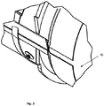
- Each conduit section 20 has a first, female engagement formation 40 defined by a flared end portion of the conduit section 20, having an increased diameter. A portion of the female engagement formation 40 is depicted in Fig. 3 .
- Each conduit section 20 has an opposing, second, male engagement formation 42 defined by an end 42 of the conduit section 20.
- the first engagement formation 40 and the second engagement formation 42 are located at opposing ends of the conduit section 20.
- Fig. 1 there are three interconnected conduit sections 20. However, there is no limit to how many conduit sections 20 may be interconnected.
- each conduit section 20 is adapted to selectively engage with an adjacent, like conduit section 20.
- the two semi-tubular sections 30a, 30b which define each conduit section 20 engage with each other along the two longitudinally extending parallel edges by means of a third engagement formation 50 defined by a longitudinally extending rib 52, and a fourth engagement formation 60 defined by a longitudinally extending slot or groove 54.
- the rib 52 and the groove 54 may be integrally formed with each semi-tubular section 30a, 30b during manufacture.
- the rib 52 and the groove 54 may be defined by a first, separately formed sealing profile 56 containing the groove 54 (best seen in Fig. 4 ) and a second, separately formed sealing profile 58 containing the rib 52 (best seen in Fig. 5 ).
- sealing profile 56 includes a longitudinally extending channel 57. This channel 57 is intended to be seated on one of the longitudinally extending edges of each semi-tubular sections 30a, 30b.
- the sealing profile 56 may be secured to the semi-tubular section 30a, 30b with a suitable adhesive, such as urethane. Additional fasteners, such as stainless steel bolts may also be used.
- the groove 54 is flared or outwardly tapering, such that the extension lip 59 is located along the radially outer surface of the semi-tubular sections 30a, 30b.
- the extension lip provides a guide surface which assists when bringing two of the semi-tubular sections 30a, 30b into abutment.
- this reduces the required level of lateral alignment, as the extension lip 59 can accommodate some degree of lateral misalignment.
- the circular void 53 formed at the base of the groove 54 provides increased material flexibility between the two arms which define the groove 54.
- the second sealing profile 58 includes a channel 63 which is seated on one of the longitudinally extending edges of each semi-tubular sections 30a, 30b.
- the sealing profile 58 may be secured to the semi-tubular section 30a, 30b with a suitable adhesive, such as urethane. Additional fasteners, such as stainless steel bolts may also be used.
- Each semi-tubular section 30a, 30b includes one of the first sealing profiles 56 and one of the second sealing profiles 58.
- the rib 52 is defined by a tapering projection.
- the reduced cross-sectional area of the rib 52 toward the tip also assists in guiding the rib 52 into the groove 54.
- Fig. 2 is a partial perspective view showing the overlap region between two adjacent conduit sections 20.
- the interaction between the third engagement formation 50 and the fourth engagement formation 60 can be clearly seen.
- the interaction between the third engagement formation 50 and the fourth engagement formation 60 serves the purpose of improving the seal between the semi-tubular sections 30a, 30b. In addition, it assists in locating the semi-tubular section 30a, 30b in the correct orientation relative to each other.
- each conduit section 20 includes a plurality of radially extending stiffening bands 70.
- a plurality of longitudinally extending stiffening ribs may also be included.
- the stiffening bands 70 provide improved strength and rigidity, whilst keeping the weight of each conduit section 20 to a minimum. As such, a single worker can generally lift and handle one of the semi-tubular sections 30a, 30b unassisted.
- the stiffening bands 70 may be integrally formed with the semi-tubular sections 30a, 30b during manufacture. Alternatively, the semi-tubular section 30a, 30b may be secured to the semi-tubular section 30a, 30b after manufacture. The securement may be achieved with adhesives, plastic welding or using suitable fasteners. The post-manufacture installation of the stiffening bands 70 is particularly useful when retrofitting the invention to existing ventilation tubing.
- each rib 52 preferably includes a cut-out 71.
- the cut-out is generally triangular, although it will be appreciated that the cut-out 71 may be provided in other shapes.
- the cut-out 71 interacts with a corresponding tooth 73 which is also triangular and formed within the groove 54.
- the interaction between the cut-out 71 and the tooth 73 defines a means of correctly locating longitudinally the two semi-tubular section 30a, 30b relative to each other.
- the tapering nature of the tooth 73 serves to pulling the semi-tubular sections 30a, 30b into axial alignment if they are sufficiently closely aligned.
- each stiffening band 70 includes a notch or cut-out 72, which defines a lug 77.
- the lugs 77 provide stacking support when the semi-tubular sections 30a, 30b are nested in a vertical stack. This stacking arrangement is depicted in Figs. 6 to 8 , and applies during storage or transportation conditions.
- Each pair of semi-tubular sections 30a, 30b is secured to each other with a plurality of cables or straps 90, best seen in Fig. 2 .
- the straps 90 may be fixed length straps, with just enough length to engage with a fastener 92 formed on an outer wall of the semi-tubular sections 30a, 30b.
- the straps 90 may be retractable ratchet straps, which enable a varied amount of force and tensioning to be applied.
- the straps 90 have eyelets 93 which engage with pins 95, each pin having a flared head.
- the pins 95 are mounted on washers which distribute the strap load.
- Each semi-tubular section 30a, 30b preferably includes a number of hooks 94, specifically intended for being supported from the rib or roof of the mine, for example by hanging them from a steel mesh which is installed to the strata support bolts.
- the hooks are depicted in Fig 7 .
- Eyelets or handles 100 may be secured to each conduit section 20 for supporting the conduit section 20 from the roof, and for personnel to handle.
- each conduit section 20 can be custom made to achieve the requisite level of ventilation for a given mining application. However, it is envisaged that the typical length is around 2metres, and diameter will be approximately 600mm.
- the ventilation apparatus 10 includes angled connector pieces (not shown) for enabling the interconnection of non-linear conduit sections 20. For example, this enables the ventilation line to run at different angles and configurations, depending on the layout and gradient of the roadway in the mine.
- the connector pieces may include but are not limited to 90-degree elbows, 45-degree elbows, T pieces and degassing tubes.
- the connector pieces may each be manufactured as single annular fittings. Alternatively, they may be manufactured in halves, in a similar manner to each semi-tubular sections 30a, 30b.
- Each connector piece generally includes a male end, and a female end, in a similar manner to each conduit section 20.
- the connector pieces may be angularly adjustable, for example with a flexible bellows type section.
- the conduit sections 20 can be nested and stacked when not in use. This provides a significant improvement on the existing ventilation pipes which in contrast require a considerable volume of space to store, and which need to be stored and supported carefully to prevent them from rolling.
- Each semi-tubular section 30a, 30b can generally be installed by a single worker. This eliminates the need to purposely deploy a diesel vehicle to the cutting face area to supply vent tubes.
- the worker can retrieve one of the semi-tubular sections 30a, 30b and carry it up onto the platform of the mining machine, and hang it from the roof, to create an upper half of the conduit section 20.
- the flexible trunk will be pulled out below the semi-tubular section 30a that has already been suspended from the roof.
- the lower semi-tubular section 30b can then be attached from below, using the straps to create a fully enclosed conduit section 20 with no or minimal downtime and no loss of ventilation to the coalface at any time.
- the flexible trunk is secured to the conduit section 20 on account of the suction force generated by the auxiliary ventilation fan.
- only two workers are generally required during reclaiming of the vent tubes. That is, one worker to drive the diesel vehicle, and a second worker located in the man basket.
- the worker in the man basket removes the lower semi-tubular section 30b first, stacks it upright then removes the upper semi-tubular section 30a.
- the semi-tubular sections 30a, 30b can be nested with each other, minimising the amount of storage area occupied by the semi-tubular sections 30a, 30b in the man basket.
- Approximately twenty conduit sections 20 can be removed and stored comfortably in one man basket.
- the conduit sections 20 that have been reclaimed can be taken to the storage area by the same machine and man basket that had reclaimed them.
- the above described process is significantly faster, and only requires two workers.
- the tubes will be handled twice not six times minimizing manual handling injuries.
- the ventilation apparatus 10 reduces the amount of interaction between workers and machinery, by negating the need to have two workers in man basket during assembly of the ventilation ducting.
- the semi-tubular sections 30a, 30b when stacked and nested occupy approximately 20% of the storage space that would be required for a similar length of existing ventilation tubes. This provides advantages during storage above ground, storage within the mine, and transportation.
Landscapes
- Engineering & Computer Science (AREA)
- Mining & Mineral Resources (AREA)
- General Engineering & Computer Science (AREA)
- Life Sciences & Earth Sciences (AREA)
- General Life Sciences & Earth Sciences (AREA)
- Geochemistry & Mineralogy (AREA)
- Geology (AREA)
- Mechanical Engineering (AREA)
- Rigid Pipes And Flexible Pipes (AREA)
- Refuse Collection And Transfer (AREA)
- Ventilation (AREA)
- Duct Arrangements (AREA)
Claims (10)
- Lüftungsvorrichtung (10) umfassend:
mehrere rohrförmige Leitungsabschnitte (20), wobei jeder Leitungsabschnitt (20) aufweist:einen ersten halbrohrförmigen Abschnitt (30a) und einen zweiten halbrohrförmigen Abschnitt (30b), wobei jeder halbrohrförmige Abschnitt (30a, 30b) ein Querschnittsprofil aufweist, das entlang einer Längsachse (XX) gesehen allgemein die Form eines offenen halbkreisförmigen Ringelements aufweist, wobei jeder des ersten halbrohrförmigen Abschnitts (30a) und eines zweiten halbrohrförmigen Abschnitts (30b) ein oder mehrere erste sich radial erstreckende Verstärkungsbänder (70) aufweist, wobei jeder des ersten und des zweiten halbrohrförmigen Abschnitts (30a, 30b) eine dritte Eingriffsausbildung (50) und eine entsprechende vierte Eingriffsausbildung (60) aufweist, wobei die dritte Eingriffsausbildung (50) eine sich der Länge nach erstreckende Rippe (52) aufweist und die vierte Eingriffsausbildung (60) eine entsprechende sich der Länge nach erstreckende Nut (54) aufweist,wobei jede rohrförmige Leitung (20) eine erste Eingriffsausbildung (40), die an einem Längsende der rohrförmigen Leitung (20) liegt, und eine zweite Eingriffsausbildung (42), die an einem gegenüberliegenden Längsende der rohrförmigen Leitung (20) liegt, aufweist,wobei die erste Eingriffsausbildung (40) durch einen aufgeweiteten Aufnahmeendabschnitt definiert ist,wobei ferner der aufgeweitete Endabschnitt angepasst ist, um einen zweiten Eingriffsabschnitt (42) aufzunehmen, der durch einen Steckervorsatz eines benachbarten rohrförmigen Leitungsabschnitt (20) definiert ist,wobei die Lüftungsvorrichtung dadurch gekennzeichnet ist, dass die sich der Länge nach erstreckende Rippe (52) eine Aussparung (71) aufweist und die sich der Länge nach erstreckende Nut (54) einen entsprechenden Zahn (73) aufweist, wobei der Zahn (73) und die Aussparung (71) angepasst sind, um zusammenzuwirken, um den ersten halbrohrförmigen Abschnitt (30a) und den zweiten halbrohrförmigen Abschnitt (30b) der Länge nach in eine Reihe zu bringen. - Lüftungsvorrichtung (10) nach Anspruch 1, wobei die Nut (54) mindestens einen sich nach außen verjüngenden Ansatz (59) aufweist, wobei der Ansatz (59) eine seitliche Führungsfläche bereitstellt, welche dabei behilflich ist, wenn zwei der halbrohrförmigen Abschnitte (30a, 30b) zum Anschlagen gebracht werden.
- Lüftungsvorrichtung (10) nach einem der vorherigen Ansprüche, wobei der erste und der zweite halbrohrförmige Abschnitt (30a, 30b) unter Verwendung von einem oder mehreren Gurten (90) im Anschlag aneinander gehalten werden.
- Lüftungsvorrichtung (10) nach einem der vorherigen Ansprüche, wobei die Leitungsabschnitte (20) aus feuerfestem antistatischem Polyethylen oder Polycarbonat hergestellt sind.
- Lüftungsvorrichtung (10) nach einem der vorherigen Ansprüche, wobei der erste halbrohrförmige Abschnitt (30a) und der zweite halbrohrförmige Abschnitt (30b) jeweils einen oder mehrere Haken (94) zum Sichern der rohrförmigen Leitungsabschnitte (20) an einem Dach oder einer Wandstruktur aufweisen.
- Lüftungsvorrichtung (10) nach einem der vorherigen Ansprüche, ferner umfassend ein oder mehrere Steckerteile, die angepasst sind, um zwei benachbarte rohrförmige Leitungsabschnitte (20) zu sichern, so dass die Längsachsen (XX) der rohrförmigen Leitungsabschnitte (20) nichtlinear sind.
- Lüftungsvorrichtung (10) nach Anspruch 6, wobei die Steckerteile ermöglichen, dass die rohrförmigen Leitungsabschnitte (20) mit einem Winkelversatz von 90 Grad oder 45 Grad verbunden werden.
- Lüftungsvorrichtung (10) nach Anspruch 1, wobei jedes Verstärkungsband (70) zwei Nuten (72) aufweist, wobei jede Nut (72) angepasst ist, um einen gegenüberliegenden Längsrand eines entsprechenden halbrohrförmigen Abschnitts (30a, 30b) zum Stapeln aufzunehmen.
- Verfahren zum Installieren einer Lüftungsvorrichtung (10) nach Anspruch 1, das Verfahren umfassend die Schritte:Sichern eines ersten halbrohrförmigen Abschnitts (30a) an einer Stützstruktur,Sichern eines zweiten halbrohrförmigen Abschnitts (30b) an dem ersten halbrohrförmigen Abschnitt (30a), um einen rohrförmigen Leitungsabschnitt (20) zu definieren, wobei der rohrförmige Leitungsabschnitt (20) eine erste Eingriffsausbildung (40), die an einem ersten Ende liegt, und eine zweite Eingriffsausbildung (42), die an einem gegenüberliegenden zweiten Ende liegt, aufweist, wobei die erste Eingriffsausbildung (40) durch einen aufgeweiteten Aufnahmeendabschnitt definiert ist, wobei der aufgeweitete Endabschnitt angepasst ist, um den zweiten Eingriffsabschnitt (42) aufzunehmen, der durch einen Steckervorsatz eines benachbarten rohrförmigen Leitungsabschnitts (20) definiert ist, undInstallieren von einem oder mehreren zusätzlichen rohrförmigen Leitungsabschnitten (20), so dass die erste Eingriffsausbildung (40) jedes rohrförmigen Leitungsabschnitts (20) in die zweite Eingriffsausbildung (42) eines benachbarten rohrförmigen Leitungsabschnitts (20) eingreift, wobeidas Verfahren dadurch gekennzeichnet ist, dass der Schritt des Sicherns eines zweiten halbrohrförmigen Abschnitts (30b) an dem ersten halbrohrförmigen Abschnitt (30a) das Umschließen sowohl des ersten als auch des zweiten halbrohrförmigen Abschnitts (30a, 30b) mit einem oder mehreren Gurten (90) und Festziehen des/der Gurts/Gurte (90), bis der erste und der zweite halbrohrförmige Abschnitt (30a, 30b) in Anschlag gebracht sind, umfasst.
- Verfahren nach Anspruch 9,
wobei jeder des ersten und des zweiten halbrohrförmigen Abschnitts (30a, 30b) zwei sich der Länge nach erstreckende, allgemein parallele Ränder aufweist, wobei jeder der Ränder eine dritte Eingriffsausbildung (50) aufweist, die durch eine sich der Länge nach erstreckende Rippe (52) definiert ist, wobei der andere Rand eine vierte Eingriffsausbildung (60) aufweist, die durch eine sich der Länge nach erstreckende Nut (54) definiert ist, wobei der Schritt des Sicherns eines zweiten halbrohrförmigen Abschnitts (30b) an dem ersten halbrohrförmigen Abschnitt (30a) das Eingreifen der jeweiligen dritten Eingriffsausbildung (50) des ersten halbrohrförmigen Abschnitts (30a) in die vierte Eingriffsausbildung (60) des zweiten halbrohrförmigen Abschnitts (30b) umfasst.
Applications Claiming Priority (2)
| Application Number | Priority Date | Filing Date | Title |
|---|---|---|---|
| AU2015900200A AU2015900200A0 (en) | 2015-01-23 | Underground ventilation apparatus and method | |
| PCT/AU2016/050033 WO2016115605A1 (en) | 2015-01-23 | 2016-01-22 | Underground ventilation apparatus and method |
Publications (3)
| Publication Number | Publication Date |
|---|---|
| EP3247882A1 EP3247882A1 (de) | 2017-11-29 |
| EP3247882A4 EP3247882A4 (de) | 2018-09-26 |
| EP3247882B1 true EP3247882B1 (de) | 2020-03-04 |
Family
ID=56416207
Family Applications (1)
| Application Number | Title | Priority Date | Filing Date |
|---|---|---|---|
| EP16739689.4A Active EP3247882B1 (de) | 2015-01-23 | 2016-01-22 | Unterirdische lüftungsvorrichtung und verfahren |
Country Status (7)
| Country | Link |
|---|---|
| US (1) | US10760420B2 (de) |
| EP (1) | EP3247882B1 (de) |
| CN (1) | CN107208481B (de) |
| AU (1) | AU2016208981B2 (de) |
| CA (1) | CA2974617C (de) |
| WO (1) | WO2016115605A1 (de) |
| ZA (1) | ZA201705722B (de) |
Families Citing this family (5)
| Publication number | Priority date | Publication date | Assignee | Title |
|---|---|---|---|---|
| US11492019B2 (en) * | 2018-01-31 | 2022-11-08 | Tata Steel Nederland Technology B.V. | Tube segment and tube for evacuated tube transport system |
| CN108412531A (zh) * | 2018-05-18 | 2018-08-17 | 西安科技大学 | 一种急倾斜厚煤层综采放顶煤的z型回风设备及方法 |
| CA3054121C (en) * | 2019-09-05 | 2022-05-03 | Thomas Fisher | Semi-rigid duct system |
| CN111577366B (zh) * | 2020-05-22 | 2021-11-26 | 甘肃辰州矿产开发有限责任公司 | 一种矿洞开采巷道通风作业工艺 |
| CN118933966B (zh) * | 2024-10-15 | 2025-01-07 | 保利澳瑞凯(江苏)矿山机械有限公司 | 一种矿井通风设备 |
Family Cites Families (20)
| Publication number | Priority date | Publication date | Assignee | Title |
|---|---|---|---|---|
| US1025186A (en) | 1912-05-07 | Burch Plow Works Co | Culvert. | |
| US1052198A (en) * | 1912-11-29 | 1913-02-04 | Harry D Wyre | Culvert-pipe. |
| US1649752A (en) * | 1925-02-13 | 1927-11-15 | Albert Pearson | Pipe sleeve |
| GB291986A (en) * | 1927-08-06 | 1928-06-14 | Frank Edward Baker | Improvements relating to motor cycle frames |
| US1948232A (en) | 1931-08-06 | 1934-02-20 | Eric E Hall | Pipe |
| GB784158A (en) | 1955-01-21 | 1957-10-02 | Mining Engineering Co Ltd | Ducting for conveying air or other gases |
| DE2802399A1 (de) | 1978-01-20 | 1979-07-26 | Oldorid Kunstoffe Gmbh | Flexible wetterlutte |
| US4318518A (en) * | 1980-03-20 | 1982-03-09 | Davis Lynwood A | Insulated hanger strap |
| US4358139A (en) | 1980-12-03 | 1982-11-09 | Peabody Abc Corporation | Coupling for mine ventilation conduits |
| DE3345570A1 (de) | 1983-12-16 | 1985-07-04 | Fa. Carl Zeiss, 7920 Heidenheim | Kupplung fuer den antrieb eines kreuztisches |
| GB8418932D0 (en) | 1984-07-25 | 1984-08-30 | Elliott G | Ventilation ducting |
| US5197767A (en) * | 1985-04-09 | 1993-03-30 | Tsubakimoto Chain Co. | Flexible supporting sheath for cables and the like |
| FR2676785B1 (fr) * | 1991-05-24 | 1994-12-02 | Spot Sa | Dispositif d'assemblage de glissieres de tobogan. |
| CN2207446Y (zh) | 1994-04-04 | 1995-09-13 | 李敬安 | 组装式复合材料输风筒 |
| JPH1151258A (ja) | 1997-08-05 | 1999-02-26 | Nippon Kokan Light Steel Kk | コルゲートパイプ |
| GB0027521D0 (en) * | 2000-11-10 | 2000-12-27 | Coniston Holdings Ltd | Pipe construction system |
| US20050109415A1 (en) * | 2003-11-21 | 2005-05-26 | Snyder Darryl L. | Two piece air duct section |
| CN201433783Y (zh) | 2009-05-14 | 2010-03-31 | 河北中工防腐科技有限公司 | 可拆装式玻璃钢风筒 |
| CN201764641U (zh) * | 2010-08-04 | 2011-03-16 | 上海盈达空调设备有限公司 | 风门主体结构 |
| EP2705290A4 (de) * | 2011-05-05 | 2014-11-05 | Pipelion Pty Ltd | Brandschutzmittel und antistatisches rohr damit |
-
2016
- 2016-01-22 US US15/544,844 patent/US10760420B2/en active Active
- 2016-01-22 WO PCT/AU2016/050033 patent/WO2016115605A1/en not_active Ceased
- 2016-01-22 EP EP16739689.4A patent/EP3247882B1/de active Active
- 2016-01-22 AU AU2016208981A patent/AU2016208981B2/en active Active
- 2016-01-22 CN CN201680007037.4A patent/CN107208481B/zh active Active
- 2016-01-22 CA CA2974617A patent/CA2974617C/en active Active
-
2017
- 2017-08-22 ZA ZA2017/05722A patent/ZA201705722B/en unknown
Non-Patent Citations (1)
| Title |
|---|
| None * |
Also Published As
| Publication number | Publication date |
|---|---|
| CN107208481A (zh) | 2017-09-26 |
| US10760420B2 (en) | 2020-09-01 |
| WO2016115605A1 (en) | 2016-07-28 |
| EP3247882A1 (de) | 2017-11-29 |
| CA2974617A1 (en) | 2016-07-28 |
| US20170362937A1 (en) | 2017-12-21 |
| ZA201705722B (en) | 2019-02-27 |
| EP3247882A4 (de) | 2018-09-26 |
| AU2016208981B2 (en) | 2017-11-30 |
| CN107208481B (zh) | 2020-10-30 |
| CA2974617C (en) | 2023-08-22 |
| AU2016208981A1 (en) | 2017-09-14 |
Similar Documents
| Publication | Publication Date | Title |
|---|---|---|
| AU2016208981B2 (en) | Underground ventilation apparatus and method | |
| RU2529991C2 (ru) | Модульное убежище и способ его сооружения | |
| US4770086A (en) | Portable ventilation safety device | |
| CN107207160B (zh) | 输送系统及其支撑框架 | |
| CN104321489B (zh) | 用于整修管井的系统 | |
| US20160369629A1 (en) | Center-pillared Full-Face Shaft Drilling Machine | |
| US20140144908A1 (en) | Modular transportable tank system and method of assembly | |
| US20120152960A1 (en) | Fluid storage tank assembly | |
| AU2010201255B2 (en) | Collapsible storage and transportation system | |
| WO2012003526A1 (en) | A suspended rail system | |
| US20120119562A1 (en) | Mine safety system | |
| JP6787772B2 (ja) | 坑内換気用ダクト | |
| US9140026B2 (en) | Telescopic pumpable props | |
| KR101186615B1 (ko) | 이동식 소형 근접 반전구 및 이를 이용한 배관 비굴착 보수 장치와 방법 | |
| GB2476386A (en) | Subsea conduit that can be spooled | |
| AU2020357475A1 (en) | A cable trough system | |
| US7708070B2 (en) | Shaft plugging system | |
| EP3631167A1 (de) | Drainagesystem | |
| CN208149353U (zh) | 一种管道运输工具 | |
| US10316990B1 (en) | Method of supplying power to equipment | |
| JP6418520B2 (ja) | 換気設備および換気方法 | |
| JP4933881B2 (ja) | 管体搬送用台車及び管体の敷設方法 | |
| US12521934B2 (en) | System and method for shaping a duct section | |
| AU2021107190A4 (en) | Mine fan installation | |
| CN103032651A (zh) | 用于修理和/或加固管道的方法 |
Legal Events
| Date | Code | Title | Description |
|---|---|---|---|
| STAA | Information on the status of an ep patent application or granted ep patent |
Free format text: STATUS: THE INTERNATIONAL PUBLICATION HAS BEEN MADE |
|
| PUAI | Public reference made under article 153(3) epc to a published international application that has entered the european phase |
Free format text: ORIGINAL CODE: 0009012 |
|
| STAA | Information on the status of an ep patent application or granted ep patent |
Free format text: STATUS: REQUEST FOR EXAMINATION WAS MADE |
|
| 17P | Request for examination filed |
Effective date: 20170823 |
|
| AK | Designated contracting states |
Kind code of ref document: A1 Designated state(s): AL AT BE BG CH CY CZ DE DK EE ES FI FR GB GR HR HU IE IS IT LI LT LU LV MC MK MT NL NO PL PT RO RS SE SI SK SM TR |
|
| AX | Request for extension of the european patent |
Extension state: BA ME |
|
| DAV | Request for validation of the european patent (deleted) | ||
| DAX | Request for extension of the european patent (deleted) | ||
| A4 | Supplementary search report drawn up and despatched |
Effective date: 20180824 |
|
| RIC1 | Information provided on ipc code assigned before grant |
Ipc: F16L 9/22 20060101ALI20180820BHEP Ipc: E21F 1/00 20060101AFI20180820BHEP Ipc: E21F 3/00 20060101ALI20180820BHEP Ipc: E21F 1/06 20060101ALI20180820BHEP Ipc: E21F 1/04 20060101ALI20180820BHEP Ipc: E21F 1/08 20060101ALI20180820BHEP |
|
| GRAP | Despatch of communication of intention to grant a patent |
Free format text: ORIGINAL CODE: EPIDOSNIGR1 |
|
| STAA | Information on the status of an ep patent application or granted ep patent |
Free format text: STATUS: GRANT OF PATENT IS INTENDED |
|
| INTG | Intention to grant announced |
Effective date: 20190918 |
|
| RIN1 | Information on inventor provided before grant (corrected) |
Inventor name: IANNI, JOSEPH |
|
| GRAS | Grant fee paid |
Free format text: ORIGINAL CODE: EPIDOSNIGR3 |
|
| GRAA | (expected) grant |
Free format text: ORIGINAL CODE: 0009210 |
|
| STAA | Information on the status of an ep patent application or granted ep patent |
Free format text: STATUS: THE PATENT HAS BEEN GRANTED |
|
| AK | Designated contracting states |
Kind code of ref document: B1 Designated state(s): AL AT BE BG CH CY CZ DE DK EE ES FI FR GB GR HR HU IE IS IT LI LT LU LV MC MK MT NL NO PL PT RO RS SE SI SK SM TR |
|
| REG | Reference to a national code |
Ref country code: GB Ref legal event code: FG4D |
|
| REG | Reference to a national code |
Ref country code: CH Ref legal event code: EP |
|
| REG | Reference to a national code |
Ref country code: AT Ref legal event code: REF Ref document number: 1240568 Country of ref document: AT Kind code of ref document: T Effective date: 20200315 |
|
| REG | Reference to a national code |
Ref country code: DE Ref legal event code: R096 Ref document number: 602016031069 Country of ref document: DE |
|
| REG | Reference to a national code |
Ref country code: IE Ref legal event code: FG4D |
|
| PG25 | Lapsed in a contracting state [announced via postgrant information from national office to epo] |
Ref country code: RS Free format text: LAPSE BECAUSE OF FAILURE TO SUBMIT A TRANSLATION OF THE DESCRIPTION OR TO PAY THE FEE WITHIN THE PRESCRIBED TIME-LIMIT Effective date: 20200304 Ref country code: FI Free format text: LAPSE BECAUSE OF FAILURE TO SUBMIT A TRANSLATION OF THE DESCRIPTION OR TO PAY THE FEE WITHIN THE PRESCRIBED TIME-LIMIT Effective date: 20200304 Ref country code: NO Free format text: LAPSE BECAUSE OF FAILURE TO SUBMIT A TRANSLATION OF THE DESCRIPTION OR TO PAY THE FEE WITHIN THE PRESCRIBED TIME-LIMIT Effective date: 20200604 |
|
| REG | Reference to a national code |
Ref country code: NL Ref legal event code: MP Effective date: 20200304 |
|
| PG25 | Lapsed in a contracting state [announced via postgrant information from national office to epo] |
Ref country code: HR Free format text: LAPSE BECAUSE OF FAILURE TO SUBMIT A TRANSLATION OF THE DESCRIPTION OR TO PAY THE FEE WITHIN THE PRESCRIBED TIME-LIMIT Effective date: 20200304 Ref country code: GR Free format text: LAPSE BECAUSE OF FAILURE TO SUBMIT A TRANSLATION OF THE DESCRIPTION OR TO PAY THE FEE WITHIN THE PRESCRIBED TIME-LIMIT Effective date: 20200605 Ref country code: LV Free format text: LAPSE BECAUSE OF FAILURE TO SUBMIT A TRANSLATION OF THE DESCRIPTION OR TO PAY THE FEE WITHIN THE PRESCRIBED TIME-LIMIT Effective date: 20200304 Ref country code: SE Free format text: LAPSE BECAUSE OF FAILURE TO SUBMIT A TRANSLATION OF THE DESCRIPTION OR TO PAY THE FEE WITHIN THE PRESCRIBED TIME-LIMIT Effective date: 20200304 Ref country code: BG Free format text: LAPSE BECAUSE OF FAILURE TO SUBMIT A TRANSLATION OF THE DESCRIPTION OR TO PAY THE FEE WITHIN THE PRESCRIBED TIME-LIMIT Effective date: 20200604 |
|
| REG | Reference to a national code |
Ref country code: LT Ref legal event code: MG4D |
|
| PG25 | Lapsed in a contracting state [announced via postgrant information from national office to epo] |
Ref country code: NL Free format text: LAPSE BECAUSE OF FAILURE TO SUBMIT A TRANSLATION OF THE DESCRIPTION OR TO PAY THE FEE WITHIN THE PRESCRIBED TIME-LIMIT Effective date: 20200304 |
|
| PG25 | Lapsed in a contracting state [announced via postgrant information from national office to epo] |
Ref country code: CZ Free format text: LAPSE BECAUSE OF FAILURE TO SUBMIT A TRANSLATION OF THE DESCRIPTION OR TO PAY THE FEE WITHIN THE PRESCRIBED TIME-LIMIT Effective date: 20200304 Ref country code: RO Free format text: LAPSE BECAUSE OF FAILURE TO SUBMIT A TRANSLATION OF THE DESCRIPTION OR TO PAY THE FEE WITHIN THE PRESCRIBED TIME-LIMIT Effective date: 20200304 Ref country code: ES Free format text: LAPSE BECAUSE OF FAILURE TO SUBMIT A TRANSLATION OF THE DESCRIPTION OR TO PAY THE FEE WITHIN THE PRESCRIBED TIME-LIMIT Effective date: 20200304 Ref country code: SM Free format text: LAPSE BECAUSE OF FAILURE TO SUBMIT A TRANSLATION OF THE DESCRIPTION OR TO PAY THE FEE WITHIN THE PRESCRIBED TIME-LIMIT Effective date: 20200304 Ref country code: EE Free format text: LAPSE BECAUSE OF FAILURE TO SUBMIT A TRANSLATION OF THE DESCRIPTION OR TO PAY THE FEE WITHIN THE PRESCRIBED TIME-LIMIT Effective date: 20200304 Ref country code: LT Free format text: LAPSE BECAUSE OF FAILURE TO SUBMIT A TRANSLATION OF THE DESCRIPTION OR TO PAY THE FEE WITHIN THE PRESCRIBED TIME-LIMIT Effective date: 20200304 Ref country code: IS Free format text: LAPSE BECAUSE OF FAILURE TO SUBMIT A TRANSLATION OF THE DESCRIPTION OR TO PAY THE FEE WITHIN THE PRESCRIBED TIME-LIMIT Effective date: 20200704 Ref country code: SK Free format text: LAPSE BECAUSE OF FAILURE TO SUBMIT A TRANSLATION OF THE DESCRIPTION OR TO PAY THE FEE WITHIN THE PRESCRIBED TIME-LIMIT Effective date: 20200304 Ref country code: PT Free format text: LAPSE BECAUSE OF FAILURE TO SUBMIT A TRANSLATION OF THE DESCRIPTION OR TO PAY THE FEE WITHIN THE PRESCRIBED TIME-LIMIT Effective date: 20200729 |
|
| REG | Reference to a national code |
Ref country code: AT Ref legal event code: MK05 Ref document number: 1240568 Country of ref document: AT Kind code of ref document: T Effective date: 20200304 |
|
| REG | Reference to a national code |
Ref country code: DE Ref legal event code: R097 Ref document number: 602016031069 Country of ref document: DE |
|
| PLBE | No opposition filed within time limit |
Free format text: ORIGINAL CODE: 0009261 |
|
| STAA | Information on the status of an ep patent application or granted ep patent |
Free format text: STATUS: NO OPPOSITION FILED WITHIN TIME LIMIT |
|
| PG25 | Lapsed in a contracting state [announced via postgrant information from national office to epo] |
Ref country code: DK Free format text: LAPSE BECAUSE OF FAILURE TO SUBMIT A TRANSLATION OF THE DESCRIPTION OR TO PAY THE FEE WITHIN THE PRESCRIBED TIME-LIMIT Effective date: 20200304 Ref country code: IT Free format text: LAPSE BECAUSE OF FAILURE TO SUBMIT A TRANSLATION OF THE DESCRIPTION OR TO PAY THE FEE WITHIN THE PRESCRIBED TIME-LIMIT Effective date: 20200304 Ref country code: AT Free format text: LAPSE BECAUSE OF FAILURE TO SUBMIT A TRANSLATION OF THE DESCRIPTION OR TO PAY THE FEE WITHIN THE PRESCRIBED TIME-LIMIT Effective date: 20200304 |
|
| 26N | No opposition filed |
Effective date: 20201207 |
|
| PG25 | Lapsed in a contracting state [announced via postgrant information from national office to epo] |
Ref country code: SI Free format text: LAPSE BECAUSE OF FAILURE TO SUBMIT A TRANSLATION OF THE DESCRIPTION OR TO PAY THE FEE WITHIN THE PRESCRIBED TIME-LIMIT Effective date: 20200304 Ref country code: PL Free format text: LAPSE BECAUSE OF FAILURE TO SUBMIT A TRANSLATION OF THE DESCRIPTION OR TO PAY THE FEE WITHIN THE PRESCRIBED TIME-LIMIT Effective date: 20200304 |
|
| REG | Reference to a national code |
Ref country code: DE Ref legal event code: R119 Ref document number: 602016031069 Country of ref document: DE |
|
| PG25 | Lapsed in a contracting state [announced via postgrant information from national office to epo] |
Ref country code: MC Free format text: LAPSE BECAUSE OF FAILURE TO SUBMIT A TRANSLATION OF THE DESCRIPTION OR TO PAY THE FEE WITHIN THE PRESCRIBED TIME-LIMIT Effective date: 20200304 |
|
| REG | Reference to a national code |
Ref country code: CH Ref legal event code: PL |
|
| GBPC | Gb: european patent ceased through non-payment of renewal fee |
Effective date: 20210122 |
|
| PG25 | Lapsed in a contracting state [announced via postgrant information from national office to epo] |
Ref country code: LU Free format text: LAPSE BECAUSE OF NON-PAYMENT OF DUE FEES Effective date: 20210122 |
|
| REG | Reference to a national code |
Ref country code: BE Ref legal event code: MM Effective date: 20210131 |
|
| PG25 | Lapsed in a contracting state [announced via postgrant information from national office to epo] |
Ref country code: FR Free format text: LAPSE BECAUSE OF NON-PAYMENT OF DUE FEES Effective date: 20210131 |
|
| PG25 | Lapsed in a contracting state [announced via postgrant information from national office to epo] |
Ref country code: DE Free format text: LAPSE BECAUSE OF NON-PAYMENT OF DUE FEES Effective date: 20210803 Ref country code: CH Free format text: LAPSE BECAUSE OF NON-PAYMENT OF DUE FEES Effective date: 20210131 Ref country code: GB Free format text: LAPSE BECAUSE OF NON-PAYMENT OF DUE FEES Effective date: 20210122 Ref country code: LI Free format text: LAPSE BECAUSE OF NON-PAYMENT OF DUE FEES Effective date: 20210131 |
|
| PG25 | Lapsed in a contracting state [announced via postgrant information from national office to epo] |
Ref country code: IE Free format text: LAPSE BECAUSE OF NON-PAYMENT OF DUE FEES Effective date: 20210122 |
|
| PG25 | Lapsed in a contracting state [announced via postgrant information from national office to epo] |
Ref country code: BE Free format text: LAPSE BECAUSE OF NON-PAYMENT OF DUE FEES Effective date: 20210131 |
|
| PG25 | Lapsed in a contracting state [announced via postgrant information from national office to epo] |
Ref country code: HU Free format text: LAPSE BECAUSE OF FAILURE TO SUBMIT A TRANSLATION OF THE DESCRIPTION OR TO PAY THE FEE WITHIN THE PRESCRIBED TIME-LIMIT; INVALID AB INITIO Effective date: 20160122 |
|
| PG25 | Lapsed in a contracting state [announced via postgrant information from national office to epo] |
Ref country code: CY Free format text: LAPSE BECAUSE OF FAILURE TO SUBMIT A TRANSLATION OF THE DESCRIPTION OR TO PAY THE FEE WITHIN THE PRESCRIBED TIME-LIMIT Effective date: 20200304 |
|
| PG25 | Lapsed in a contracting state [announced via postgrant information from national office to epo] |
Ref country code: MK Free format text: LAPSE BECAUSE OF FAILURE TO SUBMIT A TRANSLATION OF THE DESCRIPTION OR TO PAY THE FEE WITHIN THE PRESCRIBED TIME-LIMIT Effective date: 20200304 |
|
| PG25 | Lapsed in a contracting state [announced via postgrant information from national office to epo] |
Ref country code: MT Free format text: LAPSE BECAUSE OF FAILURE TO SUBMIT A TRANSLATION OF THE DESCRIPTION OR TO PAY THE FEE WITHIN THE PRESCRIBED TIME-LIMIT Effective date: 20200304 |
|
| PG25 | Lapsed in a contracting state [announced via postgrant information from national office to epo] |
Ref country code: TR Free format text: LAPSE BECAUSE OF FAILURE TO SUBMIT A TRANSLATION OF THE DESCRIPTION OR TO PAY THE FEE WITHIN THE PRESCRIBED TIME-LIMIT Effective date: 20200304 |