EP3247931B1 - Raccord rapide - Google Patents
Raccord rapide Download PDFInfo
- Publication number
- EP3247931B1 EP3247931B1 EP16709109.9A EP16709109A EP3247931B1 EP 3247931 B1 EP3247931 B1 EP 3247931B1 EP 16709109 A EP16709109 A EP 16709109A EP 3247931 B1 EP3247931 B1 EP 3247931B1
- Authority
- EP
- European Patent Office
- Prior art keywords
- main body
- annular
- quick connect
- coupling
- clamp
- Prior art date
- Legal status (The legal status is an assumption and is not a legal conclusion. Google has not performed a legal analysis and makes no representation as to the accuracy of the status listed.)
- Active
Links
Images



Classifications
-
- F—MECHANICAL ENGINEERING; LIGHTING; HEATING; WEAPONS; BLASTING
- F16—ENGINEERING ELEMENTS AND UNITS; GENERAL MEASURES FOR PRODUCING AND MAINTAINING EFFECTIVE FUNCTIONING OF MACHINES OR INSTALLATIONS; THERMAL INSULATION IN GENERAL
- F16L—PIPES; JOINTS OR FITTINGS FOR PIPES; SUPPORTS FOR PIPES, CABLES OR PROTECTIVE TUBING; MEANS FOR THERMAL INSULATION IN GENERAL
- F16L37/00—Couplings of the quick-acting type
- F16L37/08—Couplings of the quick-acting type in which the connection between abutting or axially overlapping ends is maintained by locking members
- F16L37/084—Couplings of the quick-acting type in which the connection between abutting or axially overlapping ends is maintained by locking members combined with automatic locking
- F16L37/086—Couplings of the quick-acting type in which the connection between abutting or axially overlapping ends is maintained by locking members combined with automatic locking by means of latching members pushed radially by spring-like elements
-
- F—MECHANICAL ENGINEERING; LIGHTING; HEATING; WEAPONS; BLASTING
- F16—ENGINEERING ELEMENTS AND UNITS; GENERAL MEASURES FOR PRODUCING AND MAINTAINING EFFECTIVE FUNCTIONING OF MACHINES OR INSTALLATIONS; THERMAL INSULATION IN GENERAL
- F16L—PIPES; JOINTS OR FITTINGS FOR PIPES; SUPPORTS FOR PIPES, CABLES OR PROTECTIVE TUBING; MEANS FOR THERMAL INSULATION IN GENERAL
- F16L37/00—Couplings of the quick-acting type
- F16L37/08—Couplings of the quick-acting type in which the connection between abutting or axially overlapping ends is maintained by locking members
- F16L37/12—Couplings of the quick-acting type in which the connection between abutting or axially overlapping ends is maintained by locking members using hooks, pawls, or other movable or insertable locking members
- F16L37/1215—Couplings of the quick-acting type in which the connection between abutting or axially overlapping ends is maintained by locking members using hooks, pawls, or other movable or insertable locking members using hooks provided with a screw-thread adapted to engage and mesh with an appropriate corresponding part
Definitions
- the present invention relates to a quick connect coupling.
- the present invention relates to a device for quickly connecting a conduit of a circuit carrying a fluid to a threaded or profiled male or female terminal.
- the invention falls within the field of quick connect couplings capable of rapidly and safely performing operations of connecting and disconnecting two different conduits carrying fluids, whilst avoiding cumbersome operations of manual tightening, which would require the use of spanners or other tools and assuring both mechanical tightness and a hermetic seal.
- connection step is carried out by gripping an external locking collar of the coupling and pushing the coupling itself against the terminal it is to be connected to until the latter is engaged and mechanically held and the disconnection step is carried out by acting once again on the aforesaid external locking collar.
- EP 2 320 117 A1 discloses a coupling for threaded terminals, in particular for male terminals, adapted to allow the quick coupling without needing to screw the coupling onto the male thread to be coupled. It comprises a main body which may be easily gripped by the user, within which a plurality of components allow the gripping means to be automatically coupled to the thread of the male terminal, simply following the axial pushing of the coupling. An outer mechanism directly connected to said inner components then allows the coupling to be easily disengaged.
- EP 1876381 discloses a quick connect coupling for threaded end-pieces.
- One end of the coupling intended to receive the end-piece is provided with an annular connecting body made up of a plurality of annular segment elements resiliently coupled to one another by means of a resilient ring element and having, on the inner or outer surface thereof, depending on the type of end-piece to be connected, a thread or contour configured to provide the connection with the end-piece.
- WO 2013/175351 illustrates a quick connect coupling for threaded or profiled terminals, which comprises: a central body extending between an upper end removably sealingly connectable with the terminal and a lower end connectable with a circuit; an engaging clamp operatively associated with the central body and operable at least between a first configuration, in which it is not engaged to the terminal and enables the coupling or decoupling of the central body to and from the terminal, and a second configuration, in which it is engaged to the terminal and connects the central body to the latter; activating means that are movably active on the central body and on the engaging clamp so as to enable the passage of the engaging clamp between the first and second configurations and, consequently, the coupling and decoupling of the central body to and from the terminal.
- the Applicant has set itself the objective of providing a quick connect coupling that is qualitatively superior and possibly more economical and also more compact than those of the prior art.
- the Applicant has set itself the aim, in particular, of providing a quick connect coupling that ensures a mechanical coupling (with the respective threaded or profiled terminal) that is more precise and more secure than in the case of prior art terminals and thus ensures a secure engagement also in the presence of highpressure fluids.
- the Applicant has also set itself the aim of providing a quick connect coupling that occupies little space and is in particular axially compact.
- the Applicant has also set itself the aim of providing a quick connect coupling that is simple to construct, assemble and disassemble.
- the present invention relates to a quick connect coupling per for threaded or profiled terminals, comprising:
- the Applicant has verified that the structure of said at least one clamp configured as an annular sector equipped with a control pin makes it possible to obtain a precise, fluid radial translation of the same during the movement between the first and second positions, whilst its circumferential position (i.e. the angular position around a main axis of the passage conduit) is fixed and defined. Furthermore, the Applicant has verified that the limited dimensions of the annular sectors and of the control pins enable the overall dimensions of the quick connect coupling to be considerably reduced.
- the activation devices are operatively active on the control pin, preferably on a terminal end of the control pin spaced from the annular sector.
- said terminal end of the control pin is located at a first opening of the radial seat opposite a second opening of said radial seat near the annular sector.
- the quick connect coupling is of the female type and said at least one clamp is radially further away from the main axis in the first position than in the second position.
- the quick connect coupling is of the male type and said at least one clamp is radially nearer to the main axis in the first position than in the second position.
- the radial seat is fashioned in the tubular main body.
- the coupling is female
- the annular sector is located at a surface that is radially internal to said tubular main body and the first end of the control pin is located at a surface that is radially external to said tubular main body.
- the annular sector is located at a surface that is radially external to said tubular main body and the first end of the control pin is located at a surface that is radially internal to said tubular main body.
- the quick connect coupling comprises a single clamp held in its respective angular position around the main axis by the respective control pin. In this way it is possible also to connect terminals that are not round.
- the quick connect coupling comprises a plurality of clamps arranged around the passage conduit.
- the clamps are held in the respective angular positions around the main axis by the respective control pins.
- the annular sectors of said clamps all have the same angular width.
- the respective control pin of each clamp is centred relative to the angular width of the annular sector.
- the number of said clamps is comprised between two and ten, more preferably between four and eight; even more preferably the number is equal to six.
- at least two clamps of said plurality of clamps are arranged in diametrically opposed positions relative to a main axis of the passage conduit.
- the clamps of said plurality of clamps when they are in the first position, are circumferentially spaced apart from one another and, preferably, when they are in the second position, they are circumferentially adjacent to one another.
- the clamps of said plurality of clamps when they are in the first position, are circumferentially adjacent to one another and, preferably, when they are in the second position, they are circumferentially spaced apart from one another. In one aspect, the clamps of said plurality of clamps all have the same circumferential extent.
- said at least one clamp is housed in an annular seat of the main body.
- said annular seat is radially internal.
- said annular seat is radially external.
- said at least one clamp moves radially in the annular seat. More in particular, in the movement between the first and the second position, the annular sector of the clamp moves radially in the annular seat and the respective control pin translates partly in the radial seat and partly in the annular seat.
- the annular seat acts as a guide that permits the clamps to slide freely in a radial direction while maintaining them perfectly aligned relative to the thread of the terminal.
- the quick connect coupling comprises at least one limit stop element for said at least one clamp.
- the limit stop element limits the radial movement of the clamp.
- the limit stop element limits the centripetal radial movement of the clamp.
- the limit stop element limits the centrifugal radial movement of the clamp.
- said limit stop element is part of said annular seat.
- said limit stop element is a tooth defined by the main body.
- the main body comprises an annular portion located at the first end in an axially external position relative to said at least one clamp. Said annular portion protects said at least one clamp from possible impacts. Preferably, said annular portion partly delimits the annular seat.
- said annular portion has a radially internal annular surface against which said at least one clamp axially rests.
- the axially annular surface forms the rest surface of greatest resistance on which the clamps release all the mechanical stresses and strains at the moment in which the quick connect coupling is subjected to pressure.
- the main body has at least one radially internal (female quick connect coupling) or external (male quick connect coupling) annular surface configured to come into radial contact with the male or female terminal and act as a guide and centring element for the quick connect coupling relative to said terminal.
- said at least one radially internal annular surface is borne by the annular portion.
- the guide and centring element is operative also in the presence of a reduced number of clamps.
- the activation devices comprise a substantially tubular auxiliary body which is axially slidable relative to the main body, wherein said auxiliary body has an operative portion engaged or engageable with the control pin of said at least one clamp.
- said operative portion acts on the terminal end of the control pin.
- the auxiliary body comprises a locking collar radially external to the main body and axially movable over the main body.
- the coupling is female
- the operative portion is an axial end of the locking collar.
- the auxiliary body comprises a body that is radially internal relative to the main body and solidly connected to locking collar, wherein said operative portion is an axial end of the radially internal body.
- the quick connect coupling comprises at least one connecting element solidly connected to the locking collar and to the radially internal body and passing in a slot fashioned in the main body.
- the operative portion has a bevel acting against the terminal end of the control pin.
- the locking collar essentially has two functions: to generate the opening and closing of the quick connect coupling and guarantee a condition of safety again accidental release.
- the quick connect coupling comprises a substantially tubular shutter coaxial with the main body, wherein the shutter is axially movable relative to the main body, and wherein said shutter has a head end intended to come into contact with the terminal.
- the shutter comprises a gasket applied on the head end to assure the hermetic seal against the terminal.
- the coupling is female, the shutter is radially internal to the main body.
- the coupling is male, the shutter is radially external to the main body, more preferably the shutter is radially interposed between said main body and the locking collar. The shutter slides in contact with and is axially guided and centred by the main body.
- the shutter is axially movable between a forward position toward the first end of the main body, wherein it radially and at least partially surmounts said at least one clamp in order to hold it in the first position of release from the terminal, and a rearward position, wherein it frees said at least one clamp and allows the radial movement thereof.
- the quick connect coupling comprises coupling/release devices operatively active on the auxiliary body and on the shutter.
- the coupling/release devices are configured to block/unblock the axial movements of the shutter and of the auxiliary body relative to the main body via the movement of the locking collar.
- the coupling/release devices comprise a coupling/release slider coaxial with the main body and axially movable relative to the main body and relative to the shutter.
- the coupling/release devices further comprise at least one coupling/release element (more preferably a plurality) movable in a through hole fashioned in the main body, wherein said at least one coupling/release element is engaged/engageable with the coupling/release slider and with the auxiliary body.
- said coupling/release element is a pin or a coupling/release ball.
- the function of the slider is to permit the connection of the coupling only after the clamps have completely penetrated inside the terminal to be connected, thus assuring the best conditions of grip on the thread and guaranteeing a maximum condition of mechanical tightness.
- said at least one coupling/release element is movable between a first position of axially blocking the auxiliary body and releasing the slider and a second position of axially blocking the slider and releasing the auxiliary body.
- the coupling/release slider is radially interposed between the shutter and the main body.
- the coupling/release slider is radially external to the shutter and radially internal to the main body.
- the coupling/release slider is radially external to the main body and radially internal to the shutter.
- the slider has an annular groove for housing the coupling/release element.
- the radially internal body has an annular groove for housing the coupling/release element.
- the locking collar has a radially internal stop surface configured to enter into contact with the coupling/release element.
- the quick connect coupling comprises a first spring axially interposed between the main body and the auxiliary body and configured to push said auxiliary body toward the first end of the main body.
- the first spring is radially external to the main body and radially internal to the locking collar.
- the quick connect coupling comprises a second spring axially interposed between the main body and the shutter and configured to push said shutter toward the first end of the main body.
- the second spring is radially internal to the shutter. In one embodiment, if the coupling is female, the second spring is radially internal to al main body. In a different embodiment, if the coupling is male, the second spring is radially external to the main body.
- the quick connect coupling comprises a third spring axially interposed between the main body and the coupling/release slider and configured to push said coupling/release slider toward the first end of the main body.
- the third spring is radially interposed between the main body and the shutter. In one embodiment, if the coupling is female, the third spring is radially internal to the main body and radially external to the shutter. In a different embodiment, if the coupling is male, the third spring is radially external to the main body and radially internal to the shutter.
- the quick connect coupling is movable between a first configuration corresponding to the first position of release from the terminal and a second configuration corresponding to the second position of engagement to the terminal.
- the auxiliary body is in a rearward position relative to the first end of the main body and is axially blocked relative to said main body by the coupling/release element set in the first position
- the shutter is in a forward position toward the first end of the main body and radially and at least partially surmounts said at least one clamp in order to hold it in the first position of release from the terminal
- the slider is in a forward position toward the first end of the main body.
- the coupling/release element lies outside the annular groove of the slider.
- the coupling/release element lies in the groove of the radially internal body.
- the coupling/release element lies against the stop surface of the locking collar.
- the coupling if the coupling is male, the slider pushes axially against the main body.
- the coupling if the coupling is female, the slider pushes axially against the shutter.
- the auxiliary body is in a rearward position relative to the first end of the main body.
- the auxiliary body is in a forward position toward the first end of the main body.
- the main body comprises a first portion bearing said at least one clamp and a second portion axially aligned with the first portion, wherein the first portion is removably screwed onto the second portion.
- the clamps or the single clamp
- the clamps can be easily installed before mounting the first portion on the second portion or removed after dismounting the first portion from the second portion.
- the present invention also relates to a method for constructing a quick connect comprising:
- associating the control pin comprises: making a radial hole in the annular sector and inserting therein one end of the control pin.
- the radial holes are fashioned before the ring is cut into sectors.
- control pins are associated with the annular sectors at the time of being mounted on the respective main body.
- the method comprises mounting one or more annular sectors of a ring on main bodies belonging to different quick connect couplings.
- the method comprises mounting each of the annular sectors of the ring on a main body of a respective quick connect coupling.
- the method comprises mounting diametrically opposed pairs of annular sectors of said ring on different main bodies belonging to different quick connect couplings. In this manner, with a single ring it is possible to produce a number of quick connect couplings with a saving of materials and processing.
- the present invention also relates to a method for mounting a quick connect coupling, preferably in accordance with one or more of the preceding aspects and/or of the appended claims, comprising:
- the present invention also relates to a method for dismounting a quick connect coupling, preferably in accordance with one or more of the preceding aspects and/or of the appended claims, comprising:
- FIG. 1 denotes in its entirety a quick connect coupling for threaded or profiled terminals.
- Figure 1 illustrates, in particular, a female quick connect coupling associated with a male threaded terminal 2.
- the upper radial half-section of figure 1 illustrates the quick connect coupling 1 in a first configuration in which the terminal 2 is separated and disengaged from the quick connect coupling 1.
- the lower radial half-section of the figure 1 illustrates the quick connect coupling 1 in a second configuration in which the terminal 2 is engaged to the quick connect coupling 1.
- the quick connect coupling 1 comprises a substantially tubular main body 3 that extends along a main axis "X-X".
- the main body 3 is made up of a first substantially tubular portion 4 that is axially adjacent and removably screwed to a second substantially tubular portion 5.
- the main body 3 has a first end 6 (belonging to the first portion 3) configured to be removably connected with the terminal 2 and a second end 7 (belonging to the second portion 5) opposite the first end 6 and configured to be connected, for example in a known manner (for example by screwing), with a pipe (not illustrated) of a circuit.
- the first portion 4 of the main body 3 has an annular end portion 8 which delimits, in an axially internal position and in cooperation with the second portion 5, an annular seat 9 turned radially toward the main axis "X-X" and coaxial with said main axis "X-X".
- the main body 3 has a plurality of radial seats 10 defined by through openings in the wall of the first portion 4. Said annular seats 10 are angularly equally spaced and open in a bottom surface of the aforesaid annular seat 9.
- the main body 3 is further provided with through holes 11 axially spaced from the annular seat 9. Said through holes 11 are likewise radial, for example angularly equally spaced, and can be in a number that is equal to or different from the number of the radial seats 10. In the embodiment illustrated in figure 1 , the through holes 11 are fashioned in the wall of the second portion 5 of the main body 3.
- Said terminal end 12 has a tooth 13 which extends axially in the aforesaid annular seat 9 and is radially spaced from the bottom surface of the same annular seat 9.
- the tooth 13 has the profile of a circular edge coaxial with the main axis "X-X".
- a plurality of clamps 14 is housed in the annular seat 9; each clamp is defined by a respective annular sector 15 and a control pin 16, which, at least when the clamp 14 is mounted on the coupling 1, moves solidly with the respective annular sector 15.
- the quick connect coupling 1 comprises six annular sectors 15, each of which extends angularly for about 60° around the main axis "X-X".
- Each of the annular sectors 15 has a radial hole 17, which opens radially outward and houses one end of a respective control pin 16.
- the control pins 16 extend away radially outward from the respective annular sectors 15.
- the control pin 16 has two parts with two different diameters.
- the portion with a smaller diameter is configured to be able to be easily inserted into the radial hole 17 (without being blocked therein).
- the control pin 16 and the respective annular sector 15 are held together once mounted in the annular seat 9, as will be described in detail further below.
- the control pin 16 and the respective annular sector 15 are solidly joined (for example by interference).
- each clamp 14 is centred relative to the angular width of the annular sector 15.
- Each of the annular sectors 15 has, on a radially internal surface thereof, a thread portion 18 (schematically illustrated) profiled so as to couple correctly with the externally threaded male terminal 2.
- Each of the annular sectors 15 has a stop edge 19 that projects axially and is set in a radially external position relative to the thread portion 18. In the illustrated embodiment, the stop edge 19 also extends as a circumferential arc.
- control pins 16 of each clamp 14 are housed in such a way as to be able to slide radially in the radial seats 10 and the annular sectors 15 are radially movable in the annular seat 9 independently of one another.
- each of the annular sectors 15 is movable between a first position farther away from the main axis "X-X" and a second position closer to said main axis "X-X".
- each of the annular sectors 15 lies in contact with the bottom surface of the annular seat 9 (and is held there in the manner that will be described in detail further below), with its stop edge 19 radially spaced from the tooth 13. Furthermore, a terminal end 20 radially external to the control pin 16 projects radially from a radially external surface of the main body 3.
- each of the annular sectors 15 is radially spaced from the bottom surface of the annular seat 9 (and is held there in the manner that will be described in detail further below), with its stop edge 19 in abutment against the tooth 13.
- the tooth 13 acts as a limit stop element for the respective clamp 14.
- the terminal end 20 of the control pin 16 lies flush with the radially external surface of the main body 3.
- the annular sectors 15 are radially expanded and circumferentially spaced apart from one another.
- the annular sectors 15 are radially contracted and circumferentially adjacent to one another.
- the quick connect coupling 1 comprises a substantially tubular auxiliary body 21 which is axially slidable relative to the main body 3.
- the auxiliary body 21 is a locking collar 22 which surrounds the main body 3 and can slide over it.
- a first spring 23 which lies in an annular gap delimited between the locking collar 22 and the second portion 5.
- the first spring 23 is of the helical type and coaxially surrounds the main axis "X-X".
- the first spring 23 lies in abutment against an annular surface of the main body 3 perpendicular to the main axis "X-X” and turned toward the first end 6 of the main body 3 and against an annular surface of the locking collar 22 perpendicular to the main axis "X-X” and turned toward said annular surface of the main body 3.
- the first spring 23 is configured to push the locking collar 22 toward the first end 6 of the main body 3.
- An axial end of the locking collar 22 turned toward the first end 6 of the main body 3 has a bevel defined by a first conical surface 24 which is radially internal to and diverges toward said first end 6. Said first diverging conical surface 24 forms an operative portion configured to engage with the terminal ends 20 of the control pins 16.
- the locking collar 22 and the first conical portion 24 thereof form activation devices of the quick connect coupling 1 operatively engaged with the clamps 14.
- the first conical surface 24 In the first configuration (upper radial half-section of figure 1 ), the first conical surface 24 nearly touches the terminal ends 20 of the control pins 16 which project from the main body 3, leaving a minimal amount of play.
- the second configuration lower radial half-section of figure 1
- the first conical surface 24 is set axially beyond the terminal ends 20 and lies near a conical surface 25 defined by the annular portion 8.
- the conical surface 25 of the annular portion 8 is radially external and converges toward the second end 7 of the main body 3.
- the locking collar 22 lies above the terminal ends 20 radially external to the control pins 16 and maintains the annular sectors 15 in the second position ( figure 3 ).
- the locking collar 22 has a stop surface 26 defined by a second conical radially internal surface diverging toward the first end 6 of the main body 3. Said second conical surface 26 is facing an abutment surface 27 defined by a radial enlargement of the main body 3 situated in the position of the first main body 4.
- the abutment surface 27 is radially external relative to the main body 3 and converges toward the second end 7 of said main body 3.
- the main body 3 and the locking collar 22 delimit a first chamber 28 with a variable volume (depending on the relative axial position of the locking collar 22 and of the main body 3).
- Coupling/release elements 29 defined by respective pins are inserted slidingly in the through holes 11 of the main body 3, which open into or in proximity to (depending on the configuration) the aforesaid first variable volume chamber 28.
- the pins 29 In the first configuration (upper radial half-section of figure 1 ), the pins 29 project radially outward from the respective through holes 11 (in the manner that will be described in detail further below) and the stop surface 26 of the locking collar 22 rests against radially external ends of the pins 29, pushed by the first spring 23.
- the pins 29 are completely retracted into the respective through holes 11 and the first spring 23 axially pushes the stop surface 26 of the locking collar 22 against the abutment surface 27.
- the quick connect coupling 1 of figure 1 comprises a substantially tubular shutter 30 coaxial with the main body 3.
- the shutter 30 is radially internal to the main body 3 and is axially movable relative to said main body 3.
- the shutter 30 has a central passage that is coaxial with the main axis "X-X" and delimits, together with the main body 3, a passage conduit 31 for the fluid passing through the quick connect coupling 1.
- the shutter 30 has a head end 32 provided with a suitable gasket and intended to enter into contact with a head end of the terminal 2 (second configuration illustrated in the lower radial half-section of figure 1 ).
- the shutter 30 has a stop ring 33 which is set at an end opposite the head end 32; it is radially external and configured to enter into contact with a radially internal protuberance of the main body 3, in such a way as to prevent the shutter 30 from axially exiting the first end 6 of the main body 3.
- a second spring 34 is axially interposed between the main body 3 and the shutter 30 and is configured to push said shutter 30 toward the first end 6 of the main body 3.
- the second spring 34 illustrated is of the helical type, coaxial with the main axis and housed inside the shutter 30.
- the second spring 34 lies in abutment against a locking ring 3a which extends radially inside the main body 3 and against an annular surface of the shutter 30 that is perpendicular to the main axis "X-X" and turned toward the aforesaid.
- the second spring 34 when the quick connect coupling 1 is in the first configuration, pushes the stop ring 33 against the annular protuberance.
- the quick connect coupling 1 comprises a coupling/release slider 35, which is likewise tubular, coaxial with the main body 3 and axially movable relative to the main body 3 and relative to the shutter 30.
- the coupling/release slider 35 externally surrounds the shutter 30 and is radially internal to the main body 3.
- the coupling/release slider 35 is housed in a second variable volume chamber 36 delimited radially between the main body 3 and the shutter 30.
- Said second chamber 36 further houses a third spring 37 axially interposed between the main body 3 and the coupling/release slider 36.
- the third spring 37 is of the helical type and coaxially surrounds the main axis "X-X".
- the third spring 37 lies in abutment against an annular surface of the main body 3 which is perpendicular to the main axis "X-X” and turned toward the first end 6 of the main body 3, and against an annular surface of the coupling/release slider 35 which is perpendicular to the main axis "X-X” and turned toward said annular surface of the main body 3.
- the third spring 37 is configured to push the coupling/release slider 35 toward the first end 6 of the main body 3 and against an annular surface 38 of the shutter 30 which is perpendicular to the main axis "X-X" and turned toward the annular surface of the main body 3.
- the coupling/release slider 35 has a radially external annular groove 39.
- the quick connect coupling 1 is in the first configuration.
- the coupling/release element 29 lies outside the annular groove 39 of the coupling/release slider 35.
- the coupling/release slider 35 is in abutment against the annular surface 38 of the shutter 30 and the third spring 37 pushes both the coupling/release slider 35 and the shutter 30 toward the first end 6 of the main body 3.
- the stop ring 33 holds the shutter 30 and the coupling/release slider in the main body 3 opposing the action of the second and of the third spring 34, 37.
- a radially external surface of the shutter 30 near the head end 32 is located in the position of the annular sectors 15 and faces the same.
- the radially external surface of the shutter 30 prevents the clamps 14 from closing radially and maintains the terminal ends 20 of the control pins 16 projecting from the main body 3.
- the locking collar 21 is held in an axially rearward position by the coupling/release pins 29, which project radially from the through holes 11 in such a way that the first conical surface 24 lightly touches the terminal ends 20 of the control pins 16.
- the operator grasps the locking collar 22 and inserts the male terminal 2 into the first end 6.
- the male terminal 2 rests against the head end 32 of the shutter 30 guided and centred by a radially internal annular surface 40 of the annular portion 8.
- the terminal 2 pushes the shutter 30 axially toward the second end 7, opposed by the second and third springs 34, 37, which are partially compressed.
- This movement brings the annular groove 39 of the coupling/release slider 35 near the coupling/release pin 29.
- the coupling/release pins 29 move radially, pushed by the second conical surface 26, and enter into the annular groove 39, freeing the locking collar 22, which can slide forward toward the first end 6.
- the rearward movement of the shutter 30 also frees the annular sectors 15, which can move radially inward.
- the first conical surface 24 of the locking collar 22 radially pushes the control pins 16 toward the main axis "X-X" and the annular sectors 15 are radially closed over the male terminal 2, engaging their thread portion with the thread of said male terminal 2 (lower half-section of figure 1 ).
- the coupling position is stable, since in the second configuration the axial movement of the coupling/release slider 35 is prevented by the coupling/release pin 29 held in position in the annular groove 39 by the locking collar 22 located in the forward position.
- the operator pulls the locking collar 22 away from the terminal 2, in opposition to the first spring 23.
- the locking collar 22 slides axially over the main body 3 toward the second end 7, causing the first spring 23 to be compressed until freeing the control pins 16 and bringing the second conical surface 26 onto the coupling/release pins 29.
- the clamps 14 are free to open radially, thus permitting the extraction of the male terminal 2, and simultaneously the coupling/release pins 29 move axially outward, releasing the coupling/release slider 35.
- the second and third springs 34, 37 thus push the coupling/release slider and the shutter 30 back toward the first configuration (upper half-section of figure 1 ).
- the coupling/release slider 35 and the coupling/release pins 29 constitute coupling/release devices configured to block/unblock the axial movements of the shutter 30 and of the locking collar 22 relative to the main body 3 via the movement of the locking collar 22 itself.
- the quick connect coupling is identical to the one in figure 1 , except for that fact the clamps 14 of the quick connect coupling 1 are not threaded, since they engage with the male terminal 2 of figure 2 , which is not threaded, but only profiled.
- the quick connect coupling 1 is as described above except for the fact that the clamps 14 do not extend 360° all around the main axis "X-X".
- the quick connect coupling 1 may possess only one or two or three, reciprocally adjacent along an arc of a circle of 120° or 180°. In this case, the clamps 14 close on the terminal 2 asymmetrically and push it against the radially internal annular surface 40 of the annular portion 8 of the main body 3.
- the quick connect coupling 1 can also comprise two clamps 14 set in diametrically opposed positions relative to said main axis "X-X".
- the quick connect coupling 1 is of the male type and the terminal 2 is female and internally threaded.
- the upper radial half-section of figure 6 illustrates the quick connect coupling 1 in a first configuration in which the terminal 2 is separated and disengaged from the quick connect coupling 1.
- the lower radial half-section of the figure 6 illustrates the quick connect coupling 1 in a second configuration in which the terminal 2 is engaged to the quick connect coupling 1.
- the same reference numbers have been used for the elements corresponding to those of the quick connect coupling as per figure 1 .
- the quick connect coupling 1 of figure 6 comprises a substantially tubular main body 3 which extends along a main axis "X-X" and is made up of a first portion 4 removably screwed to a second portion 5.
- the main body 3 likewise has a first end 6 and a second end 7.
- the first portion 4 of the main body 3 has an annular end portion 8 which delimits, in an axially internal position, an annular seat 9 turned radially outward, that is, on the side opposite the main axis "X-X", and coaxial with said main axis "X-X".
- the main body 3 has a plurality of radial seats 10 defined by through openings in the wall of the first portion 4. Said annular seats 10 are angularly equally spaced and open in a bottom surface of the aforesaid annular seat 9.
- the main body 3 is further provided with through holes 11 axially spaced from the annular seat 9.
- Said through holes 11 are likewise radial, for example angularly equally spaced, and can be in a number that is equal to or different from the number of the radial seats 10.
- the through holes 11 are fashioned in the wall of the first portion 4 of the main body 3 and have the purpose of favouring the pressurization of the shutter 30 during the operating phase.
- the first portion 4 comprises an annular body 41, which, together with the annular portion 8, delimits the aforesaid annular seat 9.
- Said annular body 41 has a tooth 13 that extends axially in the aforesaid annular seat 9 and is radially spaced from the bottom surface of the same annular seat 9.
- the tooth 13 has the profile of a circular edge coaxial with the main axis "X-X".
- a plurality of clamps 14 is housed in the annular seat 9; each clamp is defined by a respective annular sector 15 and a control pin 16 associated with the respective annular sector 15.
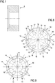
- the quick connect coupling 1 comprises six annular sectors 15, each of which extends angularly for about 60° around the main axis "X-X".
- Each of the annular sectors 15 has a radial hole 17, which opens radially inward and stably houses (for example by interference) one end of a respective control pin 16.
- the control pins 16 extend radially inward from the respective annular sectors 15.
- Each of the annular sectors 15 has, on a radially external surface, a thread portion 18 (schematically illustrated) shaped so as to couple correctly with the internally threaded female terminal.
- Each of the annular sectors 15 further has a stop edge 19 which projects axially and is set in a radially internal position relative to the thread portion 18. In the illustrated embodiment, the stop edge 19 also extends like a circumferential arc.
- Each of the annular sectors 15 is movable between a first position that is closer to the axis "X-X" and a second position that is farther away from said main axis "X-X". In the first position, each of the annular sectors 15 lies in contact with the bottom surface of the annular seat 9 (and is held there in the manner that will be described in detail further below), with its stop edge 19 radially spaced from the tooth 13. Furthermore, a radially external terminal end 20 of the control pin 16 projects radially from a radially external surface of the main body 3.
- each of the annular sectors 15 is radially spaced from the bottom surface of the annular seat 9 (and is held there in the manner that will be described in detail further below), with its stop edge 19 in abutment against the tooth 13.
- the tooth 13 acts as a limit stop element for the respective clamp 14.
- the terminal end 20 of the control pin 16 lies substantially flush with the radially internal surface of the main body 3.
- the auxiliary body 21 comprises a locking collar 22 which surrounds the main body 3 and can slide over it and a radially internal body 42 solidly connected to the locking collar 22.
- the radially internal body 42 is positioned inside the main body 3 and has an axial passage which, together with the main body 3, defines the passage conduit 31 for the fluid.
- At least one connecting element 43 is solidly connected to the locking collar 22 and to the radially internal body 42 and passes in a slot 44 which extends along the main axis "X-X" and is fashioned in the main body 3.
- the quick connect coupling 1 comprises two connecting elements 43 defined by two radially oriented screws.
- first spring 23 which lies in an annular gap delimited between the locking collar 22 and the second portion 5.
- the first spring 23 is of the helical type and coaxially surrounds the main axis "X-X".
- the first spring 23 lies in abutment against an annular surface of the main body 3 which is perpendicular to the main axis "X-X” and turned toward the first end 6 of the main body 3, and against an annular surface solidly joined with the locking collar 22 which is perpendicular to the main axis "X-X” and turned toward said annular surface of the main body 3.
- the first spring 23 is configured to push the locking collar 22 toward the first end 6 of the main body 3.
- An axial end of the radially internal body 42 turned toward the first end 6 of the main body 3 has a bevel defined by a first radially external conical surface 24 which converges toward said first end 6.
- Said first converging conical surface 24 constitutes an operative portion configured to engage with the terminal ends 20 of the control pins 16.
- the locking collar, the radially internal body 42 and the first conical portion 24 constitute activation devices of the quick connect coupling 1 operatively engaged with the clamps 14.
- the first conical surface 24 lightly touches and contains the terminal ends 20 of the control pins 16 which project from the main body 3.
- the first conical surface 24 is set axially beyond the terminal ends 20 and lies near the annular portion 8.
- the radially internal body 42 lies above the radially internal terminal ends 20 of the control pins 16 and maintains the annular sectors 15 in the second position ( figure 8 ).
- the radially internal body 42 has an annular groove 45, coaxial with the main axis "X-X", on a radially external surface.
- Coupling/release elements 29 defined by respective balls are slidingly inserted in the through holes 11 of the main body 3.
- the balls 29 project radially inward from the respective through holes 11 (in the manner that will be described in detail further below) and the projecting part thereof lies in the annular groove 45.
- the quick connect coupling 1 of figure 6 comprises a substantially tubular shutter 30 coaxial with the main body 3.
- the shutter 30 is radially external to the main body 3 and is axially movable relative to said main body 3.
- the shutter 30 is radially interposed between said main body 3 and the locking collar 22.
- the shutter 30 has a head end 32 intended to enter into contact with a head end of the terminal 2 (second configuration illustrated in the lower radial half-section of figure 6 ).
- the shutter 30 has a stop ring 33 placed at an end opposite that of the head 32, radially internal and configured to enter into contact with a radially external protuberance of the main body 3, in such a way as to prevent the axial exit of the shutter 30 from the first end 6 of the main body 3.
- a second spring 34 is axially interposed between the main body 3 and the shutter 30 and is configured to push said shutter 30 toward the first end 6 of the main body 3.
- the second spring 34 illustrated is of helical type, coaxial with the main axis.
- the second spring 34 is housed inside the shutter 30 and is radially external to the main body 3.
- the second spring 34 lies in a variable-volume annular chamber 46 delimited between the shutter 30 and the main body 3.
- the second spring 34 lies in abutment against an annular surface of the main body 3 perpendicular to the main axis "X-X" and against an annular surface of the shutter 30 perpendicular to the main axis "X-X” and turned toward the aforesaid annular surface of the main body 3.
- the second spring 34 when the quick connect coupling 1 is in the first configuration, pushes the stop ring 33 against the annular protuberance.
- the quick connect coupling 1 comprises a coupling/release slider 35 which is likewise tubular, coaxial with the main body 3 and axially movable relative to the main body 3 and relative to the shutter 30.
- the coupling/release slider 35 externally surrounds the main body 3 and is radially internal to the shutter 30.
- the coupling/release slider 35 is housed in the annular chamber 46.
- Said annular chamber 46 further houses a third spring 37 axially interposed between the main body 3 and the coupling/release slider 36.
- the third spring 37 is of the helical type and coaxially surrounds the main axis "X-X".
- the third spring 37 lies in abutment against an annular surface of the main body 3 which is perpendicular to the main axis "X-X” and turned toward the first end 6 of the main body 3, and against an annular surface of the coupling/release slider 35 which is perpendicular to the main axis "X-X” and turned toward said annular surface of the main body 3.
- the third spring 37 is configured to push the coupling/release slider 35 toward the first end 6 of the main body 3 and against an annular surface 47 of the annular body 41 solidly joined with the main body 3, perpendicular to the main axis "X-X" and turned toward the annular surface of the main body 3.
- the coupling/release slider 35 has a radially internal annular groove 39.
- the quick connect coupling 1 is in the first configuration.
- the coupling/release element 29 (ball) lies outside the annular groove 39 of the coupling/release slider 35 and lies in the annular groove 45 of the radially internal body 42.
- the coupling/release slider 35 is in abutment against the annular surface 47 of the annular body 41, pushed by the third spring 37.
- the second spring 34 pushes the shutter 30 toward the first end 6 of the main body 3 and the stop ring 33 holds the shutter 30 in the main body 3, opposing the action of the second spring 34.
- a surface radially internal to the shutter 30 near the head end 32 is located in the position of the annular sectors 15 and faces the same.
- the surface radially internal to the shutter 30 prevents the clamps 14 from opening radially and maintains the terminal ends 20 of the control pins 16 projecting radially inward from the main body 3.
- the auxiliary body 21 is held in an axially rearward position by the coupling/release balls 29 which project radially from the through holes 11 and are partially inserted in the annular groove 45.
- the operator grasps the locking collar 22 and inserts the first end 6 in the female terminal 2.
- the female terminal 2 rests against the head end 32 of the shutter 30 guided and centred by a radially external annular surface 40 of the annular portion 8.
- the terminal 2 pushes the shutter 30 axially toward the second end 7, opposed by the second spring 34, which is partially compressed. This movement brings a radially internal crown 48 of the shutter 30 against a radially external crown 49 of the coupling/release slider 35.
- the shutter 30 rests against the coupling/release slider 35 and pushes it back toward the second end 7, opposed by the second and third springs 34, 37, which are partially compressed until the annular groove 39 of the coupling/release slider 35 arrives at the coupling/release ball 29.
- the rearward movement of the shutter 30 also frees the annular sectors 15, which can move radially toward the outside.
- the first conical surface 24 of the radially internal body 42 radially pushes the control pins 16 away from the main axis "X-X" and the annular sectors 15 open radially, engaging their thread portion with the internal thread of said female terminal 2 (lower half-section of figure 6 ).
- the coupling position is stable, since in the second configuration the axial movement of the coupling/release slider 35 is prevented by the coupling/release ball 29 held in position in the annular groove 39 by the radially internal body 42 in the forward position.
- the locking collar 22 and the radially internal body 42 slide axially on the main body 3 toward the second end 7, causing the first spring 23 to be compressed until freeing the control pins 16 and bringing the annular groove 45 of the radially internal body 42 into the position of the coupling/release balls 29.
- the clamps 14 are free to close radially, permitting the extraction of the first end 6 of the main body 3 from the female terminal 2 and simultaneously the coupling/release balls 29 move axially inward in said annular groove 45, freeing the coupling/release slider 35.
- the second and third springs 34, 37 thus push the coupling/release slider and the shutter 30 back toward the first configuration (upper half-section of figure 6 ).
- the converging conical surface 24, the tooth 13 and the shutter 30 determine the radial movement of each clamp 14, while at the same time maintaining the annular sector 15 and the respective control pin 16 joined together (in the absence of constraints, in fact, the control pin 16 is free to come out of the radial hole 17).
- the quick connect coupling is identical to the one of figure 6 , except for the fact that the clamps 14 of the quick connect coupling 1 are not threaded, since they engage with the female terminal 2 of figure 7 , which is not threaded, but only profiled.
- the quick connect male coupling 1 is as described above, except for the fact that the clamps 14 do not extend 360° all around the main axis "X-X", analogously to what was described for the female terminal.
- the present invention also relates to a method for constructing a quick connect coupling 1 of the above-described type (male in figure 1 or female in figure 6 , threaded or non-threaded, figures 2 and 7 ).
- the method relates to the construction of the clamps 14.
- a complete ring 50 is made first (threaded if the clamps must be so).
- the ring 50 is perforated so as to create the radial holes 17 and then cut into the annular sectors 15.
- the control pins 16 are inserted into said radial holes 17.
- the cuts are made along radial lines and the radial holes 17 are centred relative to the angular width of the respective annular sectors 15.
- the clamps 14 obtained from a single ring 50 are then mounted on a single quick connect coupling 1 so as to form a complete series which extends all around the main axis "X-X" for 360°.
- the annular sectors Prior to cutting, the annular sectors are marked, for example by writing a number at each radial hole.
- the numbering can be progressive in a clockwise or anticlockwise direction. Thanks to the marking of each annular sector 15 made prior to the cut, it will be possible to correctly compose the sectors in such a way as to obtain the original continuity in the pattern of the threaded surface, if present.
- the clamps 14 obtained from a single ring 50 are installed on different quick connect couplings 1.
- a single clamp 14 is installed on each of six different quick connect couplings 1 or three pairs of clamps 14 are mounted on three different quick connect couplings 1.
- Each of said pairs comprises, for example, two clamps 14 of said single ring 50 disposed in diametrically opposed positions relative to a central axis of the ring 50.
- the clamps 14 are first mounted on the first portion 4 of the main body 3, which is then screwed onto the second portion 5.
- it is instead sufficient to unscrew the first portion 4 from the second 5 in order to remove the clamps 14.
- the locking collar 22 is fitted onto the second portion 5 of the main body 3 with the interposition of the first spring 23.
- the first portion 4 with the clamps 14 is then screwed onto the second portion 5.
- the coupling/release pins 29 are fitted into the through holes 11 and then the shutter 30 with the coupling/release slider 35 and the third spring 37 are fitted through the first end 6 and secured by mounting the stop ring 33.
- the second spring 34 is then inserted through the second end 7 and the locking ring 3a is mounted.
- the first portion 4 (with the clamps 14, the annular body 41, the coupling/release slider 35 and the third spring 37) is screwed onto the second portion 5.
- the shutter 30 is then fitted onto the main body 3 from the first end 6 with the second spring 34 and secured by mounting the stop ring 33.
- the coupling/release balls 29 are placed in the through holes 11.
- the locking collar 22 is fitted onto the main body 3 with the interposition of the first spring 23 and the radially internal body 42 is fitted into the second end 7.
- the locking collar 22 and the radially internal body 42 are constrained with the screws 43.
Landscapes
- Engineering & Computer Science (AREA)
- General Engineering & Computer Science (AREA)
- Mechanical Engineering (AREA)
- Quick-Acting Or Multi-Walled Pipe Joints (AREA)
- Mechanical Coupling Of Light Guides (AREA)
Claims (15)
- Raccord à connexion rapide pour organes effecteurs filetés ou profilés, comprenant :un corps principal sensiblement tubulaire (3) délimitant au plan interne un conduit de passage (31) pour un liquide, où ledit corps principal (3) présente une première extrémité (6) configurée pour être connectée amovible à un organe effecteur (2) et une seconde extrémité (7) opposée à la première extrémité (6) et configurée pour être connectée à un circuit ;un obturateur sensiblement tubulaire (30) coaxial avec le corps principal, où l'obturateur (30) est mobile axialement par rapport au corps principal (3), et où ledit obturateur (30) présente une extrémité de tête (32) prévue pour entrer en contact avec l'organe effecteur (2) ;au moins un étrier (14) fonctionnellement engagé au niveau du corps principal (3) au niveau de la première extrémité (6), où ledit au moins un étrier (14) comprend un secteur annulaire (15) et est radialement mobile par rapport au corps principal (3) entre une première position de libération depuis l'organe effecteur (2) et une seconde position d'engagement avec l'organe effecteur (2) ;caractérisé en ce que ledit au moins un étrier (14) comprend une broche de régulation (16) montée sur le secteur annulaire respectif (15), radialement orientée et engagée de manière coulissante dans une assise radiale respective (10) façonnée dans le corps principal (3) ;des dispositifs d'activation (21, 22, 24 ; 21, 22, 24, 42) fonctionnellement engagés avec ledit au moins un étrier (14) afin de déterminer son passage entre la première position et la seconde position.
- Raccord à connexion rapide selon la revendication 1, dans lequel les dispositifs d'activation (21, 22, 24 ; 21, 22, 24, 42) sont fonctionnellement actifs sur une extrémité terminale (20) de la broche de régulation (16) espacée du secteur annulaire (15).
- Raccord à connexion rapide selon la revendication 2, dans lequel ladite extrémité terminale (20) de la broche de régulation (16) est localisée au niveau d'une première ouverture de l'assise radiale (10) opposée à une seconde ouverture de ladite assise radiale (10) près du secteur annulaire (15).
- Raccord à connexion rapide selon l'une des revendications 1, 2 ou 3, où les dispositifs d'activation (21, 22, 24 ; 21, 22, 24, 42) comprennent un corps auxiliaire sensiblement tubulaire (21) qui peut axialement coulisser par rapport au corps principal (3).
- Raccord à connexion rapide selon la revendication 4, dans lequel ledit corps auxiliaire (21) présente une partie fonctionnelle (24) engagée ou pouvant être engagée avec la broche de régulation (16) dudit au moins un étrier (14), et où ladite partie fonctionnelle (24) agit sur l'extrémité terminale (20) de la broche de régulation (16).
- Raccord à connexion rapide selon la revendication 5, dans lequel la partie fonctionnelle (24) présente un chanfrein agissant contre l'extrémité terminale (20) de la broche de régulation (16).
- Raccord à connexion rapide selon l'une des revendications précédentes 1 à 6, dans lequel l'obturateur (30) est axialement mobile par rapport au corps principal (3) entre une position avant vers la première extrémité (6) du corps principal (3), dans laquelle il surmonte radialement et au moins partiellement ledit au moins un étrier (14) afin de le maintenir dans la première position de libération depuis l'organe effecteur (2), et une position vers l'arrière, dans laquelle il libère ledit au moins un étrier (14) et permet son mouvement radial.
- Raccord à connexion rapide selon l'une des revendications précédentes 1 à 7, ledit au moins un étrier (14) étant maintenu dans sa position angulaire respective autour de l'axe principal (X-X) par la broche de régulation respective (16).
- Raccord à connexion rapide selon l'une des revendications précédentes 1 à 8, comprenant un étrier unique (14) ou une pluralité d'étriers (14) disposés autour du conduit de passage (31), où au moins deux étriers (14) de ladite pluralité d'étriers (14) sont disposés dans des positions diamétralement opposées par rapport à un axe principal (X-X) du conduit de passage (31).
- Raccord à connexion rapide selon l'une des revendications précédentes 1 à 9, dans lequel ledit au moins un étrier (14) est logé dans une assise annulaire (9) du corps principal (3), et où, dans le mouvement entre la première et la seconde position, ledit au moins un étrier (14) se déplace radialement dans l'assise annulaire (9).
- Raccord à connexion rapide selon l'une des revendications précédentes 1 à 10, comprenant au moins un élément d'arrêt limite (13) pour ledit au moins un étrier (14), où ledit élément d'arrêt limite (13) fait partie de ladite assise annulaire (9).
- Raccord à connexion rapide selon l'une des revendications précédentes 1 à 11, dans lequel le corps principal (3) comprend une partie annulaire (8) localisée au niveau de la première extrémité (6) dans une position axialement externe par rapport audit au moins un étrier (14), et où ladite partie annuelle (8) présente une surface annulaire axialement interne (8a) contre laquelle ledit au moins un étrier (14) repose axialement.
- Procédé de fabrication d'un raccord à connexion rapide selon l'une ou plusieurs des revendications précédentes 1 à 12, dans lequel le procédé comprend :la fabrication d'un anneau complet (50) ;la coupe de l'anneau complet (50) en une pluralité de secteurs annulaires (15) ;l'association d'une broche de régulation (16) à chacun des secteurs annulaires (15), formant une pluralité d'étriers (14) ;le montage d'au moins l'un desdits étriers (14) dans une assise annulaire (9) façonnée dans une première partie (4) du corps principal (3) et l'insertion de la broche de régulation respective (16) dans une assise radiale (10) façonnée dans ladite première partie (4) ;le vissage de la première partie (4) avec les étriers (14) sur une seconde partie (5) du corps principal (3).
- Procédé selon la revendication 13, dans lequel les broches de régulation (16) sont associées aux secteurs annulaires (15) au moment d'être montées sur le corps principal respectif (3).
- Procédé selon la revendication 13 ou 14, comprenant : le montage d'un ou plusieurs secteurs annulaires (15) d'un anneau (50) sur les corps principaux (3) appartenant à différents raccords à connexion rapide (1); et/ou comprenant le montage de paires diamétralement opposées des secteurs annulaires (15) dudit anneau (50) sur différents corps principaux (3) appartenant à différents raccords à connexion rapide (1).
Applications Claiming Priority (2)
| Application Number | Priority Date | Filing Date | Title |
|---|---|---|---|
| ITMI2015A000056A ITMI20150056A1 (it) | 2015-01-21 | 2015-01-21 | Innesto rapido. |
| PCT/IB2016/050101 WO2016116827A1 (fr) | 2015-01-21 | 2016-01-11 | Raccord rapide |
Publications (2)
| Publication Number | Publication Date |
|---|---|
| EP3247931A1 EP3247931A1 (fr) | 2017-11-29 |
| EP3247931B1 true EP3247931B1 (fr) | 2019-05-22 |
Family
ID=52727247
Family Applications (1)
| Application Number | Title | Priority Date | Filing Date |
|---|---|---|---|
| EP16709109.9A Active EP3247931B1 (fr) | 2015-01-21 | 2016-01-11 | Raccord rapide |
Country Status (5)
| Country | Link |
|---|---|
| EP (1) | EP3247931B1 (fr) |
| DK (1) | DK3247931T3 (fr) |
| ES (1) | ES2741601T3 (fr) |
| IT (1) | ITMI20150056A1 (fr) |
| WO (1) | WO2016116827A1 (fr) |
Cited By (1)
| Publication number | Priority date | Publication date | Assignee | Title |
|---|---|---|---|---|
| EP4040028A1 (fr) | 2021-02-05 | 2022-08-10 | Staubli Faverges | Élément de raccord |
Families Citing this family (2)
| Publication number | Priority date | Publication date | Assignee | Title |
|---|---|---|---|---|
| IT201800004125A1 (it) * | 2018-03-30 | 2019-09-30 | Polo S R L | Innesto rapido per terminali filettati o sagomati |
| CN111515991A (zh) * | 2020-04-30 | 2020-08-11 | 广州富港万嘉智能科技有限公司 | 快接座、快接组件、快接工装 |
Family Cites Families (2)
| Publication number | Priority date | Publication date | Assignee | Title |
|---|---|---|---|---|
| GB503031A (en) * | 1937-10-18 | 1939-03-30 | Christopher Briscoe | Improvements relating to hose couplings and like connections |
| EP2320117B1 (fr) * | 2009-11-06 | 2012-03-07 | Faster S.P.A. | Couplage rapide de terminaux filetés mâles ou de terminaux doté d'un profil de connexion similaire |
-
2015
- 2015-01-21 IT ITMI2015A000056A patent/ITMI20150056A1/it unknown
-
2016
- 2016-01-11 WO PCT/IB2016/050101 patent/WO2016116827A1/fr not_active Ceased
- 2016-01-11 EP EP16709109.9A patent/EP3247931B1/fr active Active
- 2016-01-11 DK DK16709109.9T patent/DK3247931T3/da active
- 2016-01-11 ES ES16709109T patent/ES2741601T3/es active Active
Non-Patent Citations (1)
| Title |
|---|
| None * |
Cited By (2)
| Publication number | Priority date | Publication date | Assignee | Title |
|---|---|---|---|---|
| EP4040028A1 (fr) | 2021-02-05 | 2022-08-10 | Staubli Faverges | Élément de raccord |
| FR3119657A1 (fr) | 2021-02-05 | 2022-08-12 | Staubli Faverges | Elément de raccord |
Also Published As
| Publication number | Publication date |
|---|---|
| WO2016116827A1 (fr) | 2016-07-28 |
| DK3247931T3 (da) | 2019-08-26 |
| EP3247931A1 (fr) | 2017-11-29 |
| ES2741601T3 (es) | 2020-02-11 |
| ITMI20150056A1 (it) | 2016-07-21 |
Similar Documents
| Publication | Publication Date | Title |
|---|---|---|
| JP6467040B2 (ja) | モジュラー工作機械器具受容器 | |
| AU616523B2 (en) | Pressure-sealed plug coupling | |
| EP3247931B1 (fr) | Raccord rapide | |
| US10690279B2 (en) | Valve connector | |
| CN109571220B (zh) | 用于清洁控制阀的阀体的工具和方法 | |
| CN1289849C (zh) | 具有滑动套筒和夹钳的连接器 | |
| AU2017266442B2 (en) | Fluid coupling assembly | |
| US6758457B2 (en) | Connecting member for a fast-fit safety coupling | |
| CN114935057A (zh) | 连接器元件 | |
| EP3839313B1 (fr) | Embout et prise de charge | |
| WO2014161907A1 (fr) | Dispositif de raccord rapide pour fluide sous pression | |
| EP3320250B1 (fr) | Raccord rapide | |
| US20130099482A1 (en) | Coupling device and connector including such a device | |
| CN103244780B (zh) | 用于流体通道的分割件及带有该分割件的流体技术的装置 | |
| EP3387315B1 (fr) | Coupleur fluidique à faible émission | |
| CN104908306B (zh) | 嵌件夹持机构 | |
| US9387576B1 (en) | Faucet seat and spring inserter | |
| GB2038970A (en) | Fluid flow couplings | |
| CN114017567B (zh) | 一种气动快插接头 | |
| EP2220416B1 (fr) | Couvercle d'un élément de couplage fluide | |
| CN102095030A (zh) | 计量表用连接螺母的不正当拆卸的防止装置 | |
| EP3931479B1 (fr) | Raccord rapide | |
| EP2280208A1 (fr) | Raccord rapide de terminaux filetés femelles ou de terminaux doté d'un profil de connexion similaire | |
| EP1236948A1 (fr) | Dispositif de connexion amovible pour conduites | |
| TWI645925B (zh) | Front-mounted hydraulic chuck |
Legal Events
| Date | Code | Title | Description |
|---|---|---|---|
| STAA | Information on the status of an ep patent application or granted ep patent |
Free format text: STATUS: THE INTERNATIONAL PUBLICATION HAS BEEN MADE |
|
| PUAI | Public reference made under article 153(3) epc to a published international application that has entered the european phase |
Free format text: ORIGINAL CODE: 0009012 |
|
| STAA | Information on the status of an ep patent application or granted ep patent |
Free format text: STATUS: REQUEST FOR EXAMINATION WAS MADE |
|
| 17P | Request for examination filed |
Effective date: 20170712 |
|
| AK | Designated contracting states |
Kind code of ref document: A1 Designated state(s): AL AT BE BG CH CY CZ DE DK EE ES FI FR GB GR HR HU IE IS IT LI LT LU LV MC MK MT NL NO PL PT RO RS SE SI SK SM TR |
|
| AX | Request for extension of the european patent |
Extension state: BA ME |
|
| DAV | Request for validation of the european patent (deleted) | ||
| DAX | Request for extension of the european patent (deleted) | ||
| RAP1 | Party data changed (applicant data changed or rights of an application transferred) |
Owner name: POLO S.R.L. |
|
| RIN1 | Information on inventor provided before grant (corrected) |
Inventor name: POZZI MARCO Inventor name: LOCATELLI SILVIA |
|
| RAP1 | Party data changed (applicant data changed or rights of an application transferred) |
Owner name: POLO S.R.L. |
|
| GRAP | Despatch of communication of intention to grant a patent |
Free format text: ORIGINAL CODE: EPIDOSNIGR1 |
|
| STAA | Information on the status of an ep patent application or granted ep patent |
Free format text: STATUS: GRANT OF PATENT IS INTENDED |
|
| INTG | Intention to grant announced |
Effective date: 20181005 |
|
| GRAJ | Information related to disapproval of communication of intention to grant by the applicant or resumption of examination proceedings by the epo deleted |
Free format text: ORIGINAL CODE: EPIDOSDIGR1 |
|
| STAA | Information on the status of an ep patent application or granted ep patent |
Free format text: STATUS: REQUEST FOR EXAMINATION WAS MADE |
|
| GRAP | Despatch of communication of intention to grant a patent |
Free format text: ORIGINAL CODE: EPIDOSNIGR1 |
|
| STAA | Information on the status of an ep patent application or granted ep patent |
Free format text: STATUS: GRANT OF PATENT IS INTENDED |
|
| INTC | Intention to grant announced (deleted) | ||
| INTG | Intention to grant announced |
Effective date: 20181214 |
|
| GRAS | Grant fee paid |
Free format text: ORIGINAL CODE: EPIDOSNIGR3 |
|
| GRAA | (expected) grant |
Free format text: ORIGINAL CODE: 0009210 |
|
| STAA | Information on the status of an ep patent application or granted ep patent |
Free format text: STATUS: THE PATENT HAS BEEN GRANTED |
|
| AK | Designated contracting states |
Kind code of ref document: B1 Designated state(s): AL AT BE BG CH CY CZ DE DK EE ES FI FR GB GR HR HU IE IS IT LI LT LU LV MC MK MT NL NO PL PT RO RS SE SI SK SM TR |
|
| REG | Reference to a national code |
Ref country code: GB Ref legal event code: FG4D |
|
| REG | Reference to a national code |
Ref country code: CH Ref legal event code: EP |
|
| REG | Reference to a national code |
Ref country code: IE Ref legal event code: FG4D |
|
| REG | Reference to a national code |
Ref country code: AT Ref legal event code: REF Ref document number: 1136529 Country of ref document: AT Kind code of ref document: T Effective date: 20190615 |
|
| REG | Reference to a national code |
Ref country code: DE Ref legal event code: R096 Ref document number: 602016014275 Country of ref document: DE |
|
| REG | Reference to a national code |
Ref country code: CH Ref legal event code: NV Representative=s name: PGA S.P.A., MILANO, SUCCURSALE DI LUGANO, CH |
|
| REG | Reference to a national code |
Ref country code: DK Ref legal event code: T3 Effective date: 20190822 |
|
| REG | Reference to a national code |
Ref country code: NL Ref legal event code: FP |
|
| REG | Reference to a national code |
Ref country code: SE Ref legal event code: TRGR |
|
| REG | Reference to a national code |
Ref country code: LT Ref legal event code: MG4D |
|
| REG | Reference to a national code |
Ref country code: NO Ref legal event code: T2 Effective date: 20190522 |
|
| PG25 | Lapsed in a contracting state [announced via postgrant information from national office to epo] |
Ref country code: PT Free format text: LAPSE BECAUSE OF FAILURE TO SUBMIT A TRANSLATION OF THE DESCRIPTION OR TO PAY THE FEE WITHIN THE PRESCRIBED TIME-LIMIT Effective date: 20190922 Ref country code: AL Free format text: LAPSE BECAUSE OF FAILURE TO SUBMIT A TRANSLATION OF THE DESCRIPTION OR TO PAY THE FEE WITHIN THE PRESCRIBED TIME-LIMIT Effective date: 20190522 Ref country code: FI Free format text: LAPSE BECAUSE OF FAILURE TO SUBMIT A TRANSLATION OF THE DESCRIPTION OR TO PAY THE FEE WITHIN THE PRESCRIBED TIME-LIMIT Effective date: 20190522 Ref country code: LT Free format text: LAPSE BECAUSE OF FAILURE TO SUBMIT A TRANSLATION OF THE DESCRIPTION OR TO PAY THE FEE WITHIN THE PRESCRIBED TIME-LIMIT Effective date: 20190522 Ref country code: HR Free format text: LAPSE BECAUSE OF FAILURE TO SUBMIT A TRANSLATION OF THE DESCRIPTION OR TO PAY THE FEE WITHIN THE PRESCRIBED TIME-LIMIT Effective date: 20190522 |
|
| PG25 | Lapsed in a contracting state [announced via postgrant information from national office to epo] |
Ref country code: GR Free format text: LAPSE BECAUSE OF FAILURE TO SUBMIT A TRANSLATION OF THE DESCRIPTION OR TO PAY THE FEE WITHIN THE PRESCRIBED TIME-LIMIT Effective date: 20190823 Ref country code: LV Free format text: LAPSE BECAUSE OF FAILURE TO SUBMIT A TRANSLATION OF THE DESCRIPTION OR TO PAY THE FEE WITHIN THE PRESCRIBED TIME-LIMIT Effective date: 20190522 Ref country code: BG Free format text: LAPSE BECAUSE OF FAILURE TO SUBMIT A TRANSLATION OF THE DESCRIPTION OR TO PAY THE FEE WITHIN THE PRESCRIBED TIME-LIMIT Effective date: 20190822 Ref country code: RS Free format text: LAPSE BECAUSE OF FAILURE TO SUBMIT A TRANSLATION OF THE DESCRIPTION OR TO PAY THE FEE WITHIN THE PRESCRIBED TIME-LIMIT Effective date: 20190522 |
|
| PG25 | Lapsed in a contracting state [announced via postgrant information from national office to epo] |
Ref country code: EE Free format text: LAPSE BECAUSE OF FAILURE TO SUBMIT A TRANSLATION OF THE DESCRIPTION OR TO PAY THE FEE WITHIN THE PRESCRIBED TIME-LIMIT Effective date: 20190522 Ref country code: CZ Free format text: LAPSE BECAUSE OF FAILURE TO SUBMIT A TRANSLATION OF THE DESCRIPTION OR TO PAY THE FEE WITHIN THE PRESCRIBED TIME-LIMIT Effective date: 20190522 Ref country code: RO Free format text: LAPSE BECAUSE OF FAILURE TO SUBMIT A TRANSLATION OF THE DESCRIPTION OR TO PAY THE FEE WITHIN THE PRESCRIBED TIME-LIMIT Effective date: 20190522 Ref country code: SK Free format text: LAPSE BECAUSE OF FAILURE TO SUBMIT A TRANSLATION OF THE DESCRIPTION OR TO PAY THE FEE WITHIN THE PRESCRIBED TIME-LIMIT Effective date: 20190522 |
|
| REG | Reference to a national code |
Ref country code: ES Ref legal event code: FG2A Ref document number: 2741601 Country of ref document: ES Kind code of ref document: T3 Effective date: 20200211 |
|
| REG | Reference to a national code |
Ref country code: DE Ref legal event code: R097 Ref document number: 602016014275 Country of ref document: DE |
|
| PG25 | Lapsed in a contracting state [announced via postgrant information from national office to epo] |
Ref country code: SM Free format text: LAPSE BECAUSE OF FAILURE TO SUBMIT A TRANSLATION OF THE DESCRIPTION OR TO PAY THE FEE WITHIN THE PRESCRIBED TIME-LIMIT Effective date: 20190522 Ref country code: IT Free format text: LAPSE BECAUSE OF FAILURE TO SUBMIT A TRANSLATION OF THE DESCRIPTION OR TO PAY THE FEE WITHIN THE PRESCRIBED TIME-LIMIT Effective date: 20190522 |
|
| PLBE | No opposition filed within time limit |
Free format text: ORIGINAL CODE: 0009261 |
|
| STAA | Information on the status of an ep patent application or granted ep patent |
Free format text: STATUS: NO OPPOSITION FILED WITHIN TIME LIMIT |
|
| PG25 | Lapsed in a contracting state [announced via postgrant information from national office to epo] |
Ref country code: TR Free format text: LAPSE BECAUSE OF FAILURE TO SUBMIT A TRANSLATION OF THE DESCRIPTION OR TO PAY THE FEE WITHIN THE PRESCRIBED TIME-LIMIT Effective date: 20190522 |
|
| 26N | No opposition filed |
Effective date: 20200225 |
|
| PG25 | Lapsed in a contracting state [announced via postgrant information from national office to epo] |
Ref country code: PL Free format text: LAPSE BECAUSE OF FAILURE TO SUBMIT A TRANSLATION OF THE DESCRIPTION OR TO PAY THE FEE WITHIN THE PRESCRIBED TIME-LIMIT Effective date: 20190522 |
|
| PG25 | Lapsed in a contracting state [announced via postgrant information from national office to epo] |
Ref country code: SI Free format text: LAPSE BECAUSE OF FAILURE TO SUBMIT A TRANSLATION OF THE DESCRIPTION OR TO PAY THE FEE WITHIN THE PRESCRIBED TIME-LIMIT Effective date: 20190522 |
|
| PG25 | Lapsed in a contracting state [announced via postgrant information from national office to epo] |
Ref country code: MC Free format text: LAPSE BECAUSE OF FAILURE TO SUBMIT A TRANSLATION OF THE DESCRIPTION OR TO PAY THE FEE WITHIN THE PRESCRIBED TIME-LIMIT Effective date: 20190522 |
|
| PG25 | Lapsed in a contracting state [announced via postgrant information from national office to epo] |
Ref country code: IE Free format text: LAPSE BECAUSE OF NON-PAYMENT OF DUE FEES Effective date: 20200111 |
|
| REG | Reference to a national code |
Ref country code: AT Ref legal event code: UEP Ref document number: 1136529 Country of ref document: AT Kind code of ref document: T Effective date: 20190522 |
|
| PG25 | Lapsed in a contracting state [announced via postgrant information from national office to epo] |
Ref country code: MT Free format text: LAPSE BECAUSE OF FAILURE TO SUBMIT A TRANSLATION OF THE DESCRIPTION OR TO PAY THE FEE WITHIN THE PRESCRIBED TIME-LIMIT Effective date: 20190522 Ref country code: CY Free format text: LAPSE BECAUSE OF FAILURE TO SUBMIT A TRANSLATION OF THE DESCRIPTION OR TO PAY THE FEE WITHIN THE PRESCRIBED TIME-LIMIT Effective date: 20190522 |
|
| PG25 | Lapsed in a contracting state [announced via postgrant information from national office to epo] |
Ref country code: MK Free format text: LAPSE BECAUSE OF FAILURE TO SUBMIT A TRANSLATION OF THE DESCRIPTION OR TO PAY THE FEE WITHIN THE PRESCRIBED TIME-LIMIT Effective date: 20190522 Ref country code: IS Free format text: LAPSE BECAUSE OF FAILURE TO SUBMIT A TRANSLATION OF THE DESCRIPTION OR TO PAY THE FEE WITHIN THE PRESCRIBED TIME-LIMIT Effective date: 20190922 |
|
| PGFP | Annual fee paid to national office [announced via postgrant information from national office to epo] |
Ref country code: LU Payment date: 20230124 Year of fee payment: 8 Ref country code: DK Payment date: 20230126 Year of fee payment: 8 Ref country code: AT Payment date: 20230118 Year of fee payment: 8 |
|
| PGFP | Annual fee paid to national office [announced via postgrant information from national office to epo] |
Ref country code: BE Payment date: 20230124 Year of fee payment: 8 |
|
| P01 | Opt-out of the competence of the unified patent court (upc) registered |
Effective date: 20230713 |
|
| P02 | Opt-out of the competence of the unified patent court (upc) changed |
Effective date: 20230824 |
|
| REG | Reference to a national code |
Ref country code: DK Ref legal event code: EBP Effective date: 20240131 |
|
| REG | Reference to a national code |
Ref country code: AT Ref legal event code: MM01 Ref document number: 1136529 Country of ref document: AT Kind code of ref document: T Effective date: 20240111 |
|
| PG25 | Lapsed in a contracting state [announced via postgrant information from national office to epo] |
Ref country code: LU Free format text: LAPSE BECAUSE OF NON-PAYMENT OF DUE FEES Effective date: 20240111 |
|
| PG25 | Lapsed in a contracting state [announced via postgrant information from national office to epo] |
Ref country code: LU Free format text: LAPSE BECAUSE OF NON-PAYMENT OF DUE FEES Effective date: 20240111 |
|
| PG25 | Lapsed in a contracting state [announced via postgrant information from national office to epo] |
Ref country code: BE Free format text: LAPSE BECAUSE OF NON-PAYMENT OF DUE FEES Effective date: 20240131 |
|
| PG25 | Lapsed in a contracting state [announced via postgrant information from national office to epo] |
Ref country code: AT Free format text: LAPSE BECAUSE OF NON-PAYMENT OF DUE FEES Effective date: 20240111 |
|
| PG25 | Lapsed in a contracting state [announced via postgrant information from national office to epo] |
Ref country code: BE Free format text: LAPSE BECAUSE OF NON-PAYMENT OF DUE FEES Effective date: 20240131 Ref country code: AT Free format text: LAPSE BECAUSE OF NON-PAYMENT OF DUE FEES Effective date: 20240111 |
|
| REG | Reference to a national code |
Ref country code: BE Ref legal event code: MM Effective date: 20240131 |
|
| PG25 | Lapsed in a contracting state [announced via postgrant information from national office to epo] |
Ref country code: DK Free format text: LAPSE BECAUSE OF NON-PAYMENT OF DUE FEES Effective date: 20240131 |
|
| PG25 | Lapsed in a contracting state [announced via postgrant information from national office to epo] |
Ref country code: DK Free format text: LAPSE BECAUSE OF NON-PAYMENT OF DUE FEES Effective date: 20240131 |
|
| REG | Reference to a national code |
Ref country code: CH Ref legal event code: U11 Free format text: ST27 STATUS EVENT CODE: U-0-0-U10-U11 (AS PROVIDED BY THE NATIONAL OFFICE) Effective date: 20260201 |
|
| PGFP | Annual fee paid to national office [announced via postgrant information from national office to epo] |
Ref country code: NL Payment date: 20260129 Year of fee payment: 11 |
|
| PGFP | Annual fee paid to national office [announced via postgrant information from national office to epo] |
Ref country code: SE Payment date: 20260129 Year of fee payment: 11 |
|
| PGFP | Annual fee paid to national office [announced via postgrant information from national office to epo] |
Ref country code: GB Payment date: 20260126 Year of fee payment: 11 |
|
| PGFP | Annual fee paid to national office [announced via postgrant information from national office to epo] |
Ref country code: ES Payment date: 20260210 Year of fee payment: 11 |
|
| PGFP | Annual fee paid to national office [announced via postgrant information from national office to epo] |
Ref country code: DE Payment date: 20260127 Year of fee payment: 11 Ref country code: NO Payment date: 20260203 Year of fee payment: 11 |
|
| PGFP | Annual fee paid to national office [announced via postgrant information from national office to epo] |
Ref country code: FR Payment date: 20260127 Year of fee payment: 11 |
|
| PGFP | Annual fee paid to national office [announced via postgrant information from national office to epo] |
Ref country code: CH Payment date: 20260201 Year of fee payment: 11 |