EP3247935B1 - Verfahren zum bestimmen der nullposition einer spiegeleinrichtung in einem fahrzeug-scheinwerfer - Google Patents
Verfahren zum bestimmen der nullposition einer spiegeleinrichtung in einem fahrzeug-scheinwerfer Download PDFInfo
- Publication number
- EP3247935B1 EP3247935B1 EP17702756.2A EP17702756A EP3247935B1 EP 3247935 B1 EP3247935 B1 EP 3247935B1 EP 17702756 A EP17702756 A EP 17702756A EP 3247935 B1 EP3247935 B1 EP 3247935B1
- Authority
- EP
- European Patent Office
- Prior art keywords
- light
- light module
- mirror
- opening
- module
- Prior art date
- Legal status (The legal status is an assumption and is not a legal conclusion. Google has not performed a legal analysis and makes no representation as to the accuracy of the status listed.)
- Active
Links
Images

Classifications
-
- F—MECHANICAL ENGINEERING; LIGHTING; HEATING; WEAPONS; BLASTING
- F21—LIGHTING
- F21S—NON-PORTABLE LIGHTING DEVICES; SYSTEMS THEREOF; VEHICLE LIGHTING DEVICES SPECIALLY ADAPTED FOR VEHICLE EXTERIORS
- F21S41/00—Illuminating devices specially adapted for vehicle exteriors, e.g. headlamps
- F21S41/60—Illuminating devices specially adapted for vehicle exteriors, e.g. headlamps characterised by a variable light distribution
- F21S41/67—Illuminating devices specially adapted for vehicle exteriors, e.g. headlamps characterised by a variable light distribution by acting on reflectors
- F21S41/675—Illuminating devices specially adapted for vehicle exteriors, e.g. headlamps characterised by a variable light distribution by acting on reflectors by moving reflectors
-
- B—PERFORMING OPERATIONS; TRANSPORTING
- B60—VEHICLES IN GENERAL
- B60Q—ARRANGEMENT OF SIGNALLING OR LIGHTING DEVICES, THE MOUNTING OR SUPPORTING THEREOF OR CIRCUITS THEREFOR, FOR VEHICLES IN GENERAL
- B60Q1/00—Arrangement of optical signalling or lighting devices, the mounting or supporting thereof or circuits therefor
- B60Q1/02—Arrangement of optical signalling or lighting devices, the mounting or supporting thereof or circuits therefor the devices being primarily intended to illuminate the way ahead or to illuminate other areas of way or environments
- B60Q1/04—Arrangement of optical signalling or lighting devices, the mounting or supporting thereof or circuits therefor the devices being primarily intended to illuminate the way ahead or to illuminate other areas of way or environments the devices being headlights
- B60Q1/06—Arrangement of optical signalling or lighting devices, the mounting or supporting thereof or circuits therefor the devices being primarily intended to illuminate the way ahead or to illuminate other areas of way or environments the devices being headlights adjustable, e.g. remotely-controlled from inside vehicle
- B60Q1/076—Arrangement of optical signalling or lighting devices, the mounting or supporting thereof or circuits therefor the devices being primarily intended to illuminate the way ahead or to illuminate other areas of way or environments the devices being headlights adjustable, e.g. remotely-controlled from inside vehicle by electrical means including means to transmit the movements, e.g. shafts or joints
-
- F—MECHANICAL ENGINEERING; LIGHTING; HEATING; WEAPONS; BLASTING
- F21—LIGHTING
- F21S—NON-PORTABLE LIGHTING DEVICES; SYSTEMS THEREOF; VEHICLE LIGHTING DEVICES SPECIALLY ADAPTED FOR VEHICLE EXTERIORS
- F21S41/00—Illuminating devices specially adapted for vehicle exteriors, e.g. headlamps
- F21S41/20—Illuminating devices specially adapted for vehicle exteriors, e.g. headlamps characterised by refractors, transparent cover plates, light guides or filters
- F21S41/24—Light guides
-
- F—MECHANICAL ENGINEERING; LIGHTING; HEATING; WEAPONS; BLASTING
- F21—LIGHTING
- F21S—NON-PORTABLE LIGHTING DEVICES; SYSTEMS THEREOF; VEHICLE LIGHTING DEVICES SPECIALLY ADAPTED FOR VEHICLE EXTERIORS
- F21S41/00—Illuminating devices specially adapted for vehicle exteriors, e.g. headlamps
- F21S41/30—Illuminating devices specially adapted for vehicle exteriors, e.g. headlamps characterised by reflectors
- F21S41/32—Optical layout thereof
- F21S41/36—Combinations of two or more separate reflectors
-
- F—MECHANICAL ENGINEERING; LIGHTING; HEATING; WEAPONS; BLASTING
- F21—LIGHTING
- F21S—NON-PORTABLE LIGHTING DEVICES; SYSTEMS THEREOF; VEHICLE LIGHTING DEVICES SPECIALLY ADAPTED FOR VEHICLE EXTERIORS
- F21S41/00—Illuminating devices specially adapted for vehicle exteriors, e.g. headlamps
- F21S41/40—Illuminating devices specially adapted for vehicle exteriors, e.g. headlamps characterised by screens, non-reflecting members, light-shielding members or fixed shades
-
- F—MECHANICAL ENGINEERING; LIGHTING; HEATING; WEAPONS; BLASTING
- F21—LIGHTING
- F21S—NON-PORTABLE LIGHTING DEVICES; SYSTEMS THEREOF; VEHICLE LIGHTING DEVICES SPECIALLY ADAPTED FOR VEHICLE EXTERIORS
- F21S41/00—Illuminating devices specially adapted for vehicle exteriors, e.g. headlamps
- F21S41/60—Illuminating devices specially adapted for vehicle exteriors, e.g. headlamps characterised by a variable light distribution
-
- F—MECHANICAL ENGINEERING; LIGHTING; HEATING; WEAPONS; BLASTING
- F21—LIGHTING
- F21S—NON-PORTABLE LIGHTING DEVICES; SYSTEMS THEREOF; VEHICLE LIGHTING DEVICES SPECIALLY ADAPTED FOR VEHICLE EXTERIORS
- F21S41/00—Illuminating devices specially adapted for vehicle exteriors, e.g. headlamps
- F21S41/60—Illuminating devices specially adapted for vehicle exteriors, e.g. headlamps characterised by a variable light distribution
- F21S41/65—Illuminating devices specially adapted for vehicle exteriors, e.g. headlamps characterised by a variable light distribution by acting on light sources
- F21S41/657—Illuminating devices specially adapted for vehicle exteriors, e.g. headlamps characterised by a variable light distribution by acting on light sources by moving light sources
-
- G—PHYSICS
- G01—MEASURING; TESTING
- G01M—TESTING STATIC OR DYNAMIC BALANCE OF MACHINES OR STRUCTURES; TESTING OF STRUCTURES OR APPARATUS, NOT OTHERWISE PROVIDED FOR
- G01M11/00—Testing of optical apparatus; Testing structures by optical methods not otherwise provided for
- G01M11/02—Testing optical properties
- G01M11/06—Testing the alignment of vehicle headlight devices
-
- B—PERFORMING OPERATIONS; TRANSPORTING
- B60—VEHICLES IN GENERAL
- B60Q—ARRANGEMENT OF SIGNALLING OR LIGHTING DEVICES, THE MOUNTING OR SUPPORTING THEREOF OR CIRCUITS THEREFOR, FOR VEHICLES IN GENERAL
- B60Q1/00—Arrangement of optical signalling or lighting devices, the mounting or supporting thereof or circuits therefor
- B60Q1/02—Arrangement of optical signalling or lighting devices, the mounting or supporting thereof or circuits therefor the devices being primarily intended to illuminate the way ahead or to illuminate other areas of way or environments
- B60Q1/04—Arrangement of optical signalling or lighting devices, the mounting or supporting thereof or circuits therefor the devices being primarily intended to illuminate the way ahead or to illuminate other areas of way or environments the devices being headlights
- B60Q1/06—Arrangement of optical signalling or lighting devices, the mounting or supporting thereof or circuits therefor the devices being primarily intended to illuminate the way ahead or to illuminate other areas of way or environments the devices being headlights adjustable, e.g. remotely-controlled from inside vehicle
- B60Q1/08—Arrangement of optical signalling or lighting devices, the mounting or supporting thereof or circuits therefor the devices being primarily intended to illuminate the way ahead or to illuminate other areas of way or environments the devices being headlights adjustable, e.g. remotely-controlled from inside vehicle automatically
- B60Q1/10—Arrangement of optical signalling or lighting devices, the mounting or supporting thereof or circuits therefor the devices being primarily intended to illuminate the way ahead or to illuminate other areas of way or environments the devices being headlights adjustable, e.g. remotely-controlled from inside vehicle automatically due to vehicle inclination, e.g. due to load distribution
-
- B—PERFORMING OPERATIONS; TRANSPORTING
- B60—VEHICLES IN GENERAL
- B60Q—ARRANGEMENT OF SIGNALLING OR LIGHTING DEVICES, THE MOUNTING OR SUPPORTING THEREOF OR CIRCUITS THEREFOR, FOR VEHICLES IN GENERAL
- B60Q2200/00—Special features or arrangements of vehicle headlamps
- B60Q2200/30—Special arrangements for adjusting headlamps, e.g. means for transmitting the movements for adjusting the lamps
- B60Q2200/38—Automatic calibration of motor-driven means for adjusting headlamps, i.e. when switching on the headlamps, not during mounting at factories
-
- F—MECHANICAL ENGINEERING; LIGHTING; HEATING; WEAPONS; BLASTING
- F21—LIGHTING
- F21S—NON-PORTABLE LIGHTING DEVICES; SYSTEMS THEREOF; VEHICLE LIGHTING DEVICES SPECIALLY ADAPTED FOR VEHICLE EXTERIORS
- F21S41/00—Illuminating devices specially adapted for vehicle exteriors, e.g. headlamps
- F21S41/20—Illuminating devices specially adapted for vehicle exteriors, e.g. headlamps characterised by refractors, transparent cover plates, light guides or filters
- F21S41/285—Refractors, transparent cover plates, light guides or filters not provided in groups F21S41/24 - F21S41/2805
Definitions
- the invention relates to a headlight for vehicles, for example cars, which has a light module (or several) with at least one light source and at least one mirror device, the light module being assigned an actuator, by means of which the light module can be pivoted for setting an angular position preset for operation .
- the invention also relates to a method for determining a zero position of an angular position of the light module in a headlight of the type mentioned.
- Headlights with mirror devices for redirecting the light as well as for forming a particular desired light image are well known.
- a mirror device can be a simple mirror, which can be flat or curved, or can be implemented as a micromirror array (so-called DLP, for Digital Light Processor).
- the mirror devices with the light source and possibly associated optical components are combined in a light module, and the light module is pivotably arranged in order to select a desired operating setting, for example for headlight range control.
- the setting of a desired angular position by pivoting the mirror is achieved by an actuator of a known type. The problem often arises here that a zero position of the actuator is required to reliably determine the angular position of the mirror.
- the zero position of the drive motor of the mirror is determined by moving the motor against a stop or moving over a reference position that is queried by means of a mechanical or Hall-effect sensor.
- this only allows the motor position to be determined in which additional geometrical influences on the beam path, such as tolerances in the positioning of the optical components or warping of the support frame, are not recorded.
- EP 1433 655 A2 a digital lighting device for a vehicle with a digital light reflector with a plurality of micro-mirror elements, wherein a micro-mirror element in the OFF state directs light falling on it onto an optical absorber.
- WO 02/063206 discloses a lighting system in which unwanted light components are directed into a "heat trap".
- deflected light parts are directed onto an absorber or used to generate a tail light via a light deflecting device.
- the use of light guided to the absorber to determine the zero position is not described.
- a headlight of the type mentioned above by an absorber surface with an opening, with light emanating from the light source that is deflected by the mirror device onto the absorber surface (instead of out of the headlight) being absorbed there, with the exception of Light that passes through the opening as a limited light beam, as well as through a light-sensitive sensor, which lies in the line of sight from the mirror device behind the opening and which is set up to detect the light beam passing through the opening to detect a zero position of the angular position of the light module.
- Line of sight is understood to mean an uninterrupted path of propagation of a fictitious light beam, also taking into account any optical elements such as mirrors or lenses that allow the line of sight to deviate from a simple straight line through reflection or refraction, but without causing any significant impairment of the light signal .
- the light module can be pivoted (at least) about a horizontal axis in order to carry out a headlight range adjustment.
- the mirror device can be a micromirror array; this allows light that is radiated in from the light source to be directed onto the absorber surface by at least a part of the micromirror array while the zero position is being detected.
- an arrangement is provided according to the invention in which the absorber surface is arranged stationary relative to the pivotable light module, for example as a component of the light module, whereas the sensor is arranged independently of the light module, for example fixedly mounted in the headlight outside the light module.
- the sensor is arranged relatively fixed to the pivotable light module, while the absorber surface is arranged independently of the light module, for example fixedly mounted in the headlight.
- the light beam passing through the opening of the absorber surface can strike the light-sensitive sensor directly or be deflected indirectly onto it, namely by an optically effective deflection device.
- This deflection device can e.g. be a deflecting mirror arranged in a suitable manner, or it can be a light guide arranged in a suitable manner between the opening of the absorber surface and the light-sensitive sensor.
- the deflection device can be positioned inside the light module - in particular as a component therein - or outside the light module, for example in a defined position relative to the sensor.
- the light module can e.g. be held in a support frame of the headlight, the support frame having the actuator, by means of which the light module can be pivoted for setting an angular position preset for operation.
- imaging optics are usually provided in the light path, which are preferably part of the light module, but can also be mounted in the headlight independently of the light module.
- the mirror device can be a mirror which is arranged in the beam path between the light source and the micromirror array; alternatively, the mirror can be arranged downstream of the micromirror array in the beam path.
- the mirror device in a method for determining a zero position of an angular position of a light module in a headlight according to the invention, light emanating from the light source is guided via the mirror device onto the absorber surface; the actuator can then pivot the light module with respect to its angular position, with the light-sensitive sensor being used to detect an intensity of the light beam passing through the opening.
- the zero position is detected, for example, at that angular position at which a maximum of the light intensity is detected; In other words, based on the angle-dependent measurement, the zero position is determined for that value of the angle at which the maximum of the light intensity occurs (or, alternatively, another excellent point of the angle-dependent course of the light intensity).
- a first embodiment of the invention is explained in more detail.
- the parts that are important for a headlight according to the invention are shown, it being clear that a motor vehicle headlight also contains many other parts that enable it to be used in a motor vehicle, such as in particular a car or motorcycle.
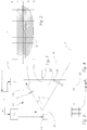
- the light-technical starting point of the headlamp is a light source 1 that emits a light beam 2 and to which a control 3 is assigned, this control 3 being used to power the light source 1 and to monitor it or, for example, to control the temperature and also to modulate the intensity of the emitted Light beam can be set up.
- modulating is understood to mean that the intensity of the light source can be changed, be it continuously or pulsed, in the sense of switching it on and off. There is also the option of switching it on and off for a certain period of time.
- LED light sources are preferably used which can be operated with high currents - one speaks of "high power LEDs" - in order to achieve the highest possible luminous flux and thus the highest possible luminance on a DMD chip.
- the control 3 receives signals from the central control unit 4.
- Signals of various types can be fed to this, e.g. Switching commands for switching from high beam to low beam or other signals that are recorded, for example, by sensors such as cameras that detect the lighting conditions, environmental conditions and / or objects on the roadway.
- the signals can also originate from vehicle-to-vehicle communication information.
- the control unit 4, shown here schematically as a block, can be arranged outside of the headlight or completely or partially contained in the headlight.
- the light source 1 can be followed by an optics 5, the design of which depends, among other things, on the type, number and spatial placement of the lighting means used, such as laser diodes or LEDs, as well as on the required beam quality, and which is primarily intended to ensure that the Light emitted from the light source strikes the micromirrors of a micromirror array 6 as homogeneously as possible.
- an optics 5 the design of which depends, among other things, on the type, number and spatial placement of the lighting means used, such as laser diodes or LEDs, as well as on the required beam quality, and which is primarily intended to ensure that the Light emitted from the light source strikes the micromirrors of a micromirror array 6 as homogeneously as possible.
- Fig. 3 shows a symbolic representation of the micromirror array 6 in a view of the area which is formed by the plurality of micromirrors of the array.
- the individual micromirrors of the micromirror array 6 can be tilted in terms of their angular position relative to the incident light beam 2.
- the focused or shaped light beam 2 now reaches this micromirror array 6, on which a luminous image 7 is formed by appropriately positioning the individual micromirrors.
- the luminous image 7 can then be projected as a light image B onto a road 9 via imaging optics 8.
- the photo B can be made visible and measured, for example for control purposes, using a temporarily set up screen 9 '; an example of such a light image B is shown in FIG Fig. 2 shown.
- the control unit 4 supplies signals s 1 to an array control 11, which controls the individual micromirrors of the array 6 in the manner corresponding to the desired light image B.
- the individual micromirrors of the array 6 can be controlled individually in terms of frequency, phase and deflection angle.
- the light parts which are not directed by the micromirrors of the array 6 to the imaging optics 8 (and through these further outwards) are directed to an absorber 12 which has a light-absorbing surface facing the mirror.
- the absorber 12 has the function of absorbing the light kept away from the array 6, as a result of which, in particular, undesired reflections in the headlight are prevented.
- the components of the beam path from the light source 1 via the array 6 to the imaging optics 8 and the absorber 12 are advantageously arranged in a light module 10 in that these components are fixedly attached, which enables a defined positional relationship of these components - in particular the light source 1, optics 5 , the array 6 and absorber 12 - is taken care of.
- the imaging optics 8 are also contained in the light module 10.
- the light module 10 can additionally, as shown in the exemplary embodiment, be mounted in a support frame 13 which holds the light module 10 or its components and can be pivoted vertically as a whole.
- the support frame 13 or the light module 10 is held by an adjustable bracket 14, preferably pivotable about a horizontal axis with the aid of the actuator of the bracket 14.
- the light module 10 can thus be adjusted in its vertical alignment with the aid of the holder 14; this bracket is used in this way to regulate the headlight range.
- the actuator of the bracket 14 can e.g. be designed as a stepper motor.
- the support frame 13 forms an adjustable "interface" to the headlight including the sensor 15 with the adjustable bracket 14.
- the support frame 13 can thus be adapted to the respective headlight; if necessary, he can also hold other modules, which can then be referenced. It is therefore generally necessary to adapt the holder / adjustment unit 14 to the current situation in the headlight in order to do justice to the respective geometry and, if applicable, the forces that occur. It is therefore usually necessary to calibrate the vertical alignment of the light module 10, thus the position of the drive of the holder 14. This is generally necessary in particular in the case of a drive implemented by a stepper motor, especially one Stepper motor is often only controlled incrementally. For calibration, a reference run is carried out through which the positioning of the holder - or the headlight range control - is determined. In this way, a zero position can be determined or established, and then starting from this position, the deflections of the drive or displacement steps of the stepper motor are counted in order to detect the current position of the drive / stepper motor.
- the position in the reference run is measured with the aid of a light-sensitive sensor 15, which is arranged behind the absorber 12 as seen from the micromirror array 6 and is mounted in such a way that its position is not influenced by the adjustment of the light module 10 by the actuator of the holder 14 becomes.
- the sensor 15 is mounted independently of the support frame 13 in the headlight, preferably outside the support frame.
- the absorber 12 there is an opening 16 ( Fig. 4 ) through which part of the light directed onto the absorber can pass in the form of a limited light beam 17.
- This light is detected by the sensor 15, which is designed, for example, as a photodiode, and a corresponding detection signal s3 is passed to the control unit 4, in which the evaluation and detection of the zero position is carried out.
- the zero position is recognized by the fact that the light passing through hits the sensor 15, while in the other positions of the drive the sensor detects no (or only slight) incidence of light.
- the opening 16 is formed in the absorber 12, more precisely in its light-absorbing surface, at a point which corresponds to the position of the drive in the zero position in order to enable the definition of the zero position.
- the opening 16 is, for example, circular or square in shape.
- the diameter d of the opening 16 is selected here to be large enough to allow a sufficient luminous flux to pass through the sensor for detection. As far as this is fulfilled, however, a small diameter d is preferred, for example less than 1 mm; this is useful in order to keep the beam 17 narrow so that a light-dark transition that can be easily recognized by the sensor can be achieved during the reference run.
- the reference run is carried out and monitored by the control unit 4.
- the micromirror array 6 is switched to dark so that all of the light is directed onto the absorber surface.
- light passes through opening 16 and is from the sensor 15 is detected.
- Fig. 5 shows an example of a detection signal F as a function of the angular position ⁇ of the array 6.
- the holder pivots the array 6 until the sensor 15 detects an edge or peak of the signal F.
- the position of the flank or the middle position of the tip is then saved as a reference value and used as the zero position for further adjustment processes.
- deflection optics can guide the light 17 passing through the opening to the sensor 15.
- the deflecting optics can be implemented, for example, with reflector surfaces, for example a mirror 18 and / or optical fibers 19.
- reflector surfaces for example a mirror 18 and / or optical fibers 19.
- other designs of the deflecting device are also possible, which can include deflecting mirrors, light guides and / or other optical components.
- the inventive arrangement of the sensor enables a reliable calibration or detection of a zero position of the drive motor of the mirror adjustment, with a small number of components that have to be recorded for the detection of the zero position.
- the dual use of the light source should be emphasized here, as it is also used for the reference run in addition to its actual function.
- Another advantage is that the reference run can be carried out more quickly because the distances to be covered by the drive motor are shorter than with conventional solutions.
- the invention makes it possible to dispense with additional sensors on the drive motor side.
- the invention allows the implicit consideration of manufacturing tolerances such as warping of the support frame, which had to be taken into account separately in conventional solutions.
Landscapes
- Engineering & Computer Science (AREA)
- General Engineering & Computer Science (AREA)
- Mechanical Engineering (AREA)
- Chemical & Material Sciences (AREA)
- Analytical Chemistry (AREA)
- Physics & Mathematics (AREA)
- General Physics & Mathematics (AREA)
- Lighting Device Outwards From Vehicle And Optical Signal (AREA)
- Non-Portable Lighting Devices Or Systems Thereof (AREA)
Description
- Die Erfindung betrifft einen Scheinwerfer für Fahrzeuge, beispielsweise PKWs, der ein Lichtmodul (oder mehrere) mit zumindest einer Lichtquelle und zumindest einer Spiegeleinrichtung aufweist, wobei dem Lichtmodul ein Stellantrieb zugeordnet ist, mittels dessen das Lichtmodul zum Einstellen einer für den Betrieb voreingestellten Winkelposition verschwenkbar ist. Die Erfindung betrifft außerdem ein Verfahren zum Bestimmen einer Nullposition einer Winkelposition des Lichtmoduls in einem Scheinwerfer der genannten Art.
- Scheinwerfer mit Spiegeleinrichtungen zum Umlenken des Lichts sowie zum Formen eines bestimmten gewünschten Lichtbildes sind wohlbekannt. Eine solche Spiegeleinrichtung kann ein einfacher Spiegel sein, der plan oder gewölbt sein kann, oder kann als Mikrospiegelarray (sogenanntes DLP, für Digital Light Processor) verwirklicht sein. In vielen Anwendungsfällen sind die Spiegeleinrichtungen mit der Lichtquelle und gegebenenfalls zugehörenden optischen Bauteilen in einem Lichtmodul zusammengefasst, und das Lichtmodul ist schwenkbar angeordnet, um eine gewünschte Betriebseinstellung auszuwählen, beispielsweise für eine Leuchtweitenregelung. Die Einstellung einer gewünschten Winkelposition durch Verschwenken des Spiegels wird durch einen Stellantrieb an sich bekannter Art erreicht. Hierbei tritt häufig die Problematik auf, dass zur zuverlässigen Festlegung der Winkelposition des Spiegels eine Nullposition des Stellantriebs vorausgesetzt wird.
- Bei herkömmlichen Lösungen wird die Nullposition des Antriebsmotors des Spiegels dadurch ermittelt, dass der Motor gegen einen Anschlag verfahren wird oder über eine Referenzposition gefahren wird, die mittels eines mechanischen oder Hall-Effekt-Sensors abgefragt wird. Dies gestattet jedoch nur eine Bestimmung der Motorposition, bei der zusätzliche geometrische Einflüsse auf den Strahlverlauf, wie z.B. Toleranzen der Positionierung der optischen Komponenten oder ein Verziehen des Tragrahmens, nicht erfasst werden.
- So beschreibt
EP 1433 655 A2 eine digitale Beleuchtungseinrichtung für ein Fahrzeug mit einem digitalen Lichtreflektor mit einer Vielzahl von Mikro-Spiegelelementen, worin ein Mikro-Spiegelelement im OFF-Status auf ihn fallendes Licht auf eine optischen Absorber lenkt.WO 02/063206 DE 197 37 653 A1 werden umgelenkte Lichtteile auf einen Absorber gelenkt oder über eine Lichtumlenkvorrichtung zur Erzeugung eines Schlusslichts verwendet. Eine Nutzung von zum Absorber geleitetem Licht für eine Bestimmung der Nullposition ist jedoch nicht beschrieben. - Es ist daher eine Aufgabe der Erfindung, die oben erwähnten Nachteile zu überwinden und eine zuverlässige Erfassung der Nullposition zu ermöglichen.
- Diese Aufgabe wird für einen Scheinwerfer der eingangs genannten Art erfindungsgemäß durch eine Absorberfläche mit einer Öffnung gelöst, wobei von der Lichtquelle ausgehendes Licht, das von der Spiegeleinrichtung auf die Absorberfläche (anstelle aus dem Scheinwerfer hinaus) umgelenkt wird, dort absorbiert wird, mit Ausnahme von Licht, das durch die Öffnung als begrenzter Lichtstrahl hindurchtritt, sowie durch einen lichtempfindlichen Sensor, welcher in Sehlinie von der Spiegeleinrichtung hinter der Öffnung liegt und welcher zum Detektieren des durch die Öffnung hindurchtretenden Lichtstrahls zum Erfassen einer Nullposition der Winkelposition des Lichtmoduls eingerichtet ist. Unter "Sehlinie" wird hierbei ein unterbrechungsfreier Ausbreitungsweg eines fiktiven Lichtstrahls verstanden, auch unter Berücksichtigung von gegebenenfalls vorhandenen optischen Elementen wie Spiegel oder Linsen, die die Sehlinie durch Reflektion oder Brechung von einer einfachen Geraden abweichen lassen, ohne jedoch zu nennenswerten Beeinträchtigungen des Lichtsignals zu führen.
- Aufgrund dieser Lösung kann durch die Öffnung in der Absorberfläche Licht als begrenzter Lichtstrahl hindurchtreten; mittels des Stellantriebs wird das Lichtmodul hinsichtlich der Winkelposition verschwenkt, wobei mittels des lichtempfindlichen Sensor eine Intensität des durch die Öffnung hindurchtretenden Lichtstrahls detektiert wird. Diese erfindungsgemäße Lösung ermöglicht eine zuverlässige Kalibrierung bzw. Erfassung einer Nullposition des Antriebmotors der Modulverstellung. Ein weiterer Vorteil ist die geringe Zahl von Komponenten, die über die eigentlichen Betriebskomponenten des Scheinwerfers hinaus vorgesehen werden, da die Lichtquelle zusätzlich für den Referenzlauf zum Einsatz kommt (doppelte Nutzung der Lichtquelle).
- In einem besonders zweckmäßigen Anwendungsfall ist das Lichtmodul zum Ausführen einer Leuchtweiteneinstellung (zumindest) um eine horizontale Achse verschwenkbar. Gemäß einer vorteilhaften Weiterbildung der Erfindung kann die Spiegeleinrichtung ein Mikrospiegelarray sein; durch dieses kann während des Erfassens der Nullposition Licht, das von der Lichtquelle eingestrahlt wird, von zumindest einem Teil des Mikrospiegelarrays auf die Absorberfläche gelenkt werden.
- Um die Messung abhängig von der Winkelposition zuverlässig zu ermöglichen, ist erfindungsgemäß eine Anordnung vorgesehen, in der die Absorberfläche relativ zum verschwenkbaren Lichtmodul feststehend angeordnet ist, z.B. als eine Komponente des Lichtmoduls, wogegen der Sensor von dem Lichtmodul unabhängig angeordnet ist, beispielsweise in dem Scheinwerfer außerhalb des Lichtmoduls fest angebracht. In einer Variante ist umgekehrt der Sensor zum verschwenkbaren Lichtmodul relativ feststehend angeordnet während die Absorberfläche von dem Lichtmodul unabhängig, z.B. im Scheinwerfer fest montiert, angeordnet ist.
- Der durch die Öffnung der Absorberfläche hindurchtretende Lichtstrahl kann direkt auf den lichtempfindlichen Sensor treffen oder auf diesen indirekt gelenkt werden, nämlich durch eine optisch wirksame Umlenkeinrichtung. Diese Umlenkeinrichtung kann z.B. ein in geeigneter Weise angeordneter Umlenkspiegel sein, oder sie kann ein in geeigneter Weise zwischen der Öffnung der Absorberfläche und dem lichtempfindlichen Sensor angeordneter Lichtleiter sein. Die Umlenkeinrichtung kann innerhalb des Lichtmoduls - insbesondere als eine Komponente darin - oder außerhalb des Lichtmoduls, beispielsweise in definierter Lage relativ zum Sensor, positioniert sein.
- Das Lichtmodul kann z.B. in einem Tragrahmen des Scheinwerfers gehalten sein, wobei der Tragrahmen den Stellantrieb aufweist, mittels dessen das Lichtmodul zum Einstellen einer für den Betrieb voreingestellten Winkelposition verschwenkbar ist. Nach der Lichtquelle und der Spiegeleinrichtung ist im Lichtgang in der Regel eine Abbildungsoptik vorgesehen, die vorzugsweise Teil des Lichtmoduls ist, jedoch auch unabhängig von dem Lichtmodul im Scheinwerfer montiert sein kann.
- Gemäß einer Variante der Erfindung kann die Spiegeleinrichtung ein Spiegel sein, der im Strahlengang zwischen der Lichtquelle und dem Mikrospiegelarray angeordnet ist; alternativ kann der Spiegel dem Mikrospiegelarray im Strahlengang nachgeordnet sein. Gemäß der Erfindung wird bei einem Verfahren zum Bestimmen einer Nullposition einer Winkelposition eines Lichtmoduls in einem erfindungsgemäßen Scheinwerfer von der Lichtquelle ausgehendes Licht über die Spiegeleinrichtung auf die Absorberfläche geleitet; der Stellantrieb kann dann das Lichtmodul hinsichtlich seiner Winkelposition verschwenken, wobei mittels des lichtempfindlichen Sensors eine Intensität des durch die Offnung hindurchtretenden Lichtstrahls detektiert wird.
- Hierbei erfolgt das Erfassen der Nullposition beispielsweise bei jener Winkelposition, bei welcher ein Maximum der Lichtintensität detektiert wird; mit anderen Worten wird aufgrund der winkelabhängigen Messung die Nullposition für jenen Wert des Winkels bestimmt, bei dem das Maximum der Lichtintensität auftritt (oder alternativ ein anderer ausgezeichneter Punkt des winkelabhängigen Verlaufs der Lichtintensität).
- Die Erfindung samt weiteren Einzelheiten und Vorzügen wird im Folgenden anhand von beispielhaften Ausführungsformen näher erläutert, die in den beigefügten Zeichnungen gezeigt sind. Die Ausführungsformen sollen die Erfindung illustrieren und sind nicht einschränkend für die Erfindung auszulegen. Die Zeichnungen zeigen in schematischer Form:
- Fig. 1
- einen KFZ-Scheinwerfer mit einem Mikrospiegelarray und einer Messeinrichtung zum Referenzieren des Mikrospiegelarrays gemäß einer Ausführungsform der Erfindung,
- Fig. 2
- ein Beispiel eines Lichtbildes, das mit einem Scheinwerfer der
Fig. 1 erzeugt werden kann; - Fig. 3
- eine Ansicht des Mikrospiegelarrays des Scheinwerfers der
Fig. 1 ; - Fig. 4
- eine Ansicht der lichtabsorbierenden Fläche eines Absorbers in dem Scheinwerfer der
Fig. 1 ; - Fig. 5
- zeigt ein Beispiel eines Messsignals der Messeinrichtung als Funktion der Winkelposition des Mikrospiegelarrays; und
- Fig. 6 und 7
- Umlenkeinrichtungen, die das zu messende Licht dem Sensor indirekt zuleiten.
- In
Fig. 1 ist ein erstes Ausführungsbeispiel der Erfindung näher erläutert. Insbesondere sind die für einen erfindungsgemäßen Scheinwerfer wichtigen Teile dargestellt, wobei es klar ist, dass ein KFZ-Scheinwerfer noch viele andere Teile enthält, die seinen sinnvollen Einsatz in einem Kraftfahrzeug, wie insbesondere einem PKW oder Motorrad, ermöglichen. Lichttechnischer Ausgangspunkt des Scheinwerfers ist eine Lichtquelle 1, die einen Lichtstrahl 2 abgibt, und welcher eine Ansteuerung 3 zugeordnet ist, wobei diese Ansteuerung 3 zur Stromversorgung der Lichtquelle 1 sowie zur deren Überwachung oder z.B. zur Temperaturkontrolle dient und auch zum Modulieren der Intensität des abgestrahlten Lichtstrahls eingerichtet sein kann. Unter "Modulieren" wird in Zusammenhang mit der vorliegenden Erfindung verstanden, dass die Intensität der Lichtquelle geändert werden kann, sei es kontinuierlich oder gepulst, im Sinne eines Ein- und Ausschaltens. Zusätzlich gibt es noch die Möglichkeit des Ein- und Ausschaltens für eine gewisse Zeit. Dabei werden in bevorzugter Weise LED-Lichtquellen verwendet, welche mit hohen Strömen betrieben werden können - man spricht von "High Power LEDs" -, um einen möglichst hohen Lichtstrom und damit eine möglichst hohe Leuchtdichte auf einem DMD-Chip zu erreichen. - Die Ansteuerung 3 erhält ihrerseits wiederum Signale von der zentralen Steuereinheit 4. Dieser können Signale verschiedener Art zugeführt werden, wie z.B. Schaltbefehle zum Umschalten von Fernlicht auf Abblendlicht oder andere Signale, die beispielsweise von Sensoren, wie Kameras, aufgenommen werden, welche die Beleuchtungsverhältnisse, Umweltbedingungen und/oder Objekte auf der Fahrbahn erfassen. Auch können die Signale von einer Fahrzeug-Fahrzeug-Kommunikationsinformation stammen. Die hier schematisch als Block gezeichnete Steuereinheit 4 kann außerhalb des Scheinwerfers angeordnet oder vollständig oder teilweise in dem Scheinwerfer enthalten sein.
- Der Lichtquelle 1 kann eine Optik 5 nachgeordnet sein, deren Ausbildung unter anderem von der Art, Anzahl und der räumlichen Platzierung der verwendeten Leuchtmittel, wie Laserdioden oder LEDs sowie von der erforderlichen Strahlqualität abhängt, und welche vor allem dafür sorgen soll, dass das von der Lichtquelle abgegebene Licht möglichst homogen auf die Mikrospiegel eines Mikrospiegelarrays 6 trifft.
-
Fig. 3 zeigt eine symbolische Darstellung des Mikrospiegelarrays 6 in einer Ansicht auf die Fläche, die durch die Vielzahl der Mikrospiegel des Arrays gebildet wird. Wie bekannt ist, können die einzelnen Mikrospiegel des Mikrospiegelarrays 6 hinsichtlich ihrer Winkelstellung relativ zum einfallenden Lichtstrahl 2 verkippt werden. - Wieder bezugnehmend auf
Fig. 1 gelangt nun der fokussierte bzw. geformte Lichtstrahl 2 zu diesem Mikrospiegelarray 6, auf welchem durch entsprechende Stellung der einzelnen Mikrospiegel ein Leuchtbild 7 geformt wird. Das Leuchtbild 7 kann sodann über eine Abbildungsoptik 8 als Lichtbild B auf eine Straße 9 projiziert werden. Das Lichtbild B kann beispielsweise zu Kontrollzwecken mithilfe eines vorübergehend aufgestellten Schirmes 9' sichtbar gemacht und gemessen werden; ein Beispiel eines derartigen Lichtbilds B ist inFig. 2 gezeigt. Die Steuereinheit 4 liefert Signale s1 an eine Arrayansteuerung 11, welche die einzelnen Mikrospiegel des Arrays 6 in der dem gewünschten Lichtbild B entsprechenden Weise ansteuert. Die einzelnen Mikrospiegel des Arrays 6 können hinsichtlich der Frequenz, der Phase und des Auslenkwinkels individuell angesteuert werden. - Die Lichtteile, die von den Mikrospiegeln des Arrays 6 nicht zur Abbildungsoptik 8 (und durch diese weiter nach außen) gelenkt werden, werden auf einen Absorber 12 geleitet, welcher dem Spiegel zugewandt eine lichtabsorbierenden Fläche aufweist. Der Absorber 12 hat die Funktion, das von dem Array 6 ferngehaltene Licht zu absorbieren, wodurch insbesondere unerwünschte Reflexionen im Scheinwerfer unterbunden werden. Die Komponenten des Strahlengangs von der Lichtquelle 1 über das Array 6 bis zur Abbildungsoptik 8 sowie der Absorber 12 sind vorteilhafterweise in einem Lichtmodul 10 angeordnet, indem diese Komponenten fest angebracht sind, wodurch für eine definierte Lagebeziehung dieser Komponenten - insbesondere der Lichtquelle 1, Optik 5, des Arrays 6 und Absorbers 12 - gesorgt ist. Häufig, aber nicht notwendiger Weise, ist auch die Abbildungsoptik 8 im Lichtmodul 10 enthalten. Das Lichtmodul 10 kann zusätzlich, wie in dem Ausführungsbeispiel gezeigt, in einem Tragrahmen 13 montiert sein, der das Lichtmodul 10 bzw. dessen Komponenten hält und als Ganzes vertikal verschwenkt werden kann. Der Tragrahmen 13 bzw. das Lichtmodul 10 ist durch eine verstellbare Halterung 14 gehalten, vorzugsweise mithilfe des Stellantriebs der Halterung 14 zumindest um eine horizontale Achse schwenkbar. Somit ist das Lichtmodul 10 in seiner vertikalen Ausrichtung mithilfe der Halterung 14 einstellbar; diese Halterung dient auf diese Weise als Leuchtweitenregelung des Scheinwerfers. Der Stellantrieb der Halterung 14 kann z.B. als Schrittmotor ausgebildet sein.
- Der Tragrahmen 13 bildet eine mit der verstellbaren Halterung 14 einstellbare "Schnittstelle" zum Scheinwerfer einschließlich des Sensors 15. Der Tragrahmen 13 kann so an den jeweiligen Scheinwerfer angepasst werden; bei Bedarf kann er auch andere Module halten, die dann mit referenziert werden können. Es ist daher im Allgemeinen erforderlich, die Halterung/Verstelleinheit 14 an die aktuelle Situation im Scheinwerfer anzupassen, um der jeweiligen Geometrie sowie gegebenenfalls den auftretenden Kräften gerecht zu werden. Somit ist es in der Regel notwendig, die vertikale Ausrichtung des Lichtmoduls 10, somit die Stellung des Antriebs der Halterung 14, zu kalibrieren. Dies ist insbesondere bei einem durch einen Schrittmotor implementierten Antrieb in der Regel erforderlich, zumal ein Schrittmotor häufig nur inkrementell angesteuert wird. Zur Kalibrierung wird ein Referenzlauf durchgeführt, durch den die Positionierung der Halterung - bzw. der Leuchtweitenregelung - ermittelt wird. Auf diese Weise kann eine Nullposition bestimmt oder festgelegt werden, und nachfolgend werden von dieser Position ausgehend die Auslenkungen des Antriebs bzw. Verfahrschritte des Schrittmotors gezählt, um die aktuelle Position des Antriebs / Schrittmotors zu erfassen.
- Gemäß der Erfindung erfolgt die Messung der Position in dem Referenzlauf mithilfe eines lichtempfindlichen Sensors 15, der vom Mikrospiegelarray 6 aus gesehen hinter dem Absorber 12 angeordnet und derart montiert ist, dass seine Position durch ein Verstellen des Lichtmoduls 10 durch den Stellantrieb der Halterung 14 nicht beeinflusst wird. Beispielsweise ist der Sensor 15 unabhängig von dem Tragrahmen 13 in dem Scheinwerfer montiert, vorzugsweise außerhalb des Tragrahmens. In dem Absorber 12 ist eine Öffnung 16 (
Fig. 4 ) ausgebildet, durch welche ein Teil des Lichts, das auf den Absorber gerichtet wird, in Form eines begrenzten Lichtstrahls 17 hindurchtreten kann. Dieses Licht wird von dem Sensor 15, der z.B. als Photodiode ausgebildet ist, detektiert, und ein dem entsprechendes Detektionssignal s3 wird an die Steuereinheit 4 geleitet, in der die Auswertung und Erfassung der Nullposition durchgeführt wird. Die Nullposition wird dadurch erkannt, dass das hindurchtretende Licht auf den Sensor 15 trifft, während in den anderen Stellungen des Antriebs der Sensor keinen (oder nur geringen) Lichteinfall detektiert. - Bezugnehmend auf
Fig. 4 ist die Öffnung 16 in dem Absorber 12, genauer gesagt in dessen lichtabsorbierender Fläche, an einer Stelle ausgebildet, die der Stellung des Antriebs in der Nullposition entspricht, um die Definition der Nullposition zu ermöglichen. Die Öffnung 16 ist beispielsweise kreisförmig oder quadratisch geformt. Der Durchmesser d der Öffnung 16 wird hierbei groß genug gewählt, um einen genügenden Lichtstrom für die Detektion durch den Sensor durchzulassen. Soweit dies erfüllt ist, wird jedoch ein kleiner Durchmesser d bevorzugt, beispielsweise unter 1 mm; dies ist zweckmäßig, um den Strahl 17 eng zu halten, damit ein mit dem Sensor gut erkennbarer Hell-Dunkel-Übergang während des Referenzlaufs erreicht werden kann. - Der Referenzlauf wird von der Steuereinheit 4 durchgeführt und überwacht. Während eines Referenzlaufs wird das Mikrospiegelarray 6 auf Dunkel geschaltet, sodass das gesamte Licht auf die Absorberfläche geleitet wird. Somit tritt Licht durch die Öffnung 16 und wird von dem Sensor 15 detektiert.
Fig. 5 zeigt ein Beispiel eines Detektionssignals F als Funktion der Winkelposition ϕ des Arrays 6. Die Halterung verschwenkt das Array 6 solange, bis der Sensor 15 eine Flanke bzw. Spitze des Signals F detektiert. Die Position der Flanke bzw. die Mittelposition der Spitze wird dann als Referenzwert gespeichert und für die weiteren Verstellvorgänge als Nullposition verwendet. - Bezugnehmend auf
Fig. 6 und 7 kann es - beispielsweise aus Platzgründen - nicht möglich oder nicht zweckmäßig sein, den Sensor 15 in Sichtlinie der Öffnung 16 zu platzieren. In einem solchen Fall kann eine Umlenkoptik (Umlenkeinrichtung) das durch die Öffnung hindurchtretende Licht 17 zu dem Sensor 15 leiten. Die Umlenkoptik kann z.B. mit Reflektorflächen, beispielsweise einem Spiegel 18 und/oder Lichtleitfasern 19 verwirklicht werden. Natürlich sind auch andere Ausführungen der Umlenkeinrichtung möglich, die Umlenkspiegel, Lichtleiter, und/oder weitere optische Komponenten umfassen können. - Die erfindungsgemäße Anordnung des Sensors ermöglicht eine zuverlässige Kalibrierung bzw. Erfassung einer Nullposition des Antriebmotors der Spiegelverstellung, mit einer geringen Zahl von Komponenten, die für die Erfassung der Nullposition aufgenommen werden müssen. Hierbei ist insbesondere die doppelte Nutzung der Lichtquelle hervorzuheben, da diese über ihre eigentliche Funktion hinaus zusätzlich für den Referenzlauf zum Einsatz kommt.
- Ein weiterer Vorteil besteht darin, dass der Referenzlauf schneller durchgeführt werden kann, weil die zurückzulegenden Wege des Antriebsmotors kleiner sind als bei herkömmlichen Lösungen.
- Durch die Ermittlung der Winkelverstellung, anstelle der Position des Motors wie bei herkömmlichen Lösungen, ermöglicht die Erfindung den Verzicht auf zusätzliche Sensorik aufseiten des Antriebsmotors. Zudem gestattet die Erfindung die implizite Berücksichtigung von Fertigungstoleranzen wie z.B. ein Verziehen des Tragrahmens, was bei herkömmlichen Lösungen gesondert berücksichtigt werden musste.
Claims (9)
- Scheinwerfer für Fahrzeuge, aufweisend zumindest ein Lichtmodul (10) mit zumindest einer Lichtquelle (1) und zumindest einer Spiegeleinrichtung (6), wobei dem Lichtmodul (10) ein Stellantrieb (14) zugeordnet ist, mittels dessen das Lichtmodul (10) zum Einstellen einer für den Betrieb voreingestellten Winkelposition verschwenkbar ist,
gekennzeichnet durch
eine Absorberfläche (12) mit einer Öffnung, wobei von der Lichtquelle (1) ausgehendes Licht, das von der Spiegeleinrichtung (6) auf die Absorberfläche (12) umgelenkt wird, dort absorbiert wird, mit Ausnahme von Licht, das durch die Öffnung (16) als begrenzter Lichtstrahl (17) hindurchtritt, sowie
einen lichtempfindlichen Sensor (15), welcher in Sehlinie von der Spiegeleinrichtung (6) hinter der Öffnung (16) liegt und welcher zum Detektieren des durch die Öffnung hindurchtretenden Lichtstrahls (17) zum Erfassen einer Nullposition der Winkelposition des Lichtmoduls (10) eingerichtet ist. ,
wobei die Absorberfläche (12) von dem Lichtmodul (10) unabhängig angeordnet ist und der Sensor (15) relativ zum verschwenkbaren Lichtmodul (10) feststehend angeordnet ist, oder die Absorberfläche (12) relativ zum verschwenkbaren Lichtmodul (10) feststehend angeordnet ist und der Sensor (15) von dem Lichtmodul (10) unabhängig angeordnet ist. - Scheinwerfer nach Anspruch 1, dadurch gekennzeichnet, dass das Lichtmodul (10) zum Ausführen einer Leuchtweiteneinstellung um eine horizontale Achse verschwenkbar ist.
- Scheinwerfer nach Anspruch 1 oder 2, dadurch gekennzeichnet, dass die Spiegeleinrichtung ein Mikrospiegelarray (6) ist, wobei der Mikrospiegelarray (6) dazu eingerichtet ist, dass während des Erfassens der Nullposition Licht, das von der Lichtquelle (1) eingestrahlt wird, von zumindest einem Teil des Mikrospiegelarrays (6) auf die Absorberfläche (12) gelenkt wird.
- Scheinwerfer nach Anspruch 1, gekennzeichnet durch eine optisch wirksame Umlenkeinrichtung (18, 19), die dazu eingerichtet ist, den durch die Öffnung (16) der Absorberfläche (12) hindurchtretenden Lichtstrahl (17) auf den lichtempfindlichen Sensor (15) zu leiten, wobei die Umlenkeinrichtung bevorzugt außerhalb des Lichtmoduls angeordnet ist.
- Scheinwerfer nach Anspruch 4, dadurch gekennzeichnet, dass die optisch wirksame Umlenkeinrichtung ein Umlenkspiegel (18) ist.
- Scheinwerfer nach Anspruch 4, dadurch gekennzeichnet, dass die optisch wirksame Umlenkeinrichtung ein zwischen der Öffnung (16) und dem lichtempfindlichen Sensor (15) befindlicher Lichtleiter (19) ist.
- Scheinwerfer nach einem der vorhergehenden Ansprüche, dadurch gekennzeichnet, dass das Lichtmodul (10) in einem Tragrahmen (13) des Scheinwerfers gehalten ist, wobei der Tragrahmen (13) den Stellantrieb (14) aufweist, mittels dessen das Lichtmodul (10) zum Einstellen einer für den Betrieb voreingestellten Winkelposition verschwenkbar ist
- Verfahren zum Bestimmen einer Nullposition einer Winkelposition eines Lichtmoduls (10) in einem Scheinwerfer nach einem der vorhergehenden Ansprüche, dadurch gekennzeichnet, dass von der Lichtquelle (1) ausgehendes Licht über die Spiegeleinrichtung (6) auf die Absorberfläche (12) geleitet wird und der Stellantrieb (14) das Lichtmodul (10) hinsichtlich seiner Winkelposition verschwenkt, wobei das Bestimmen der Nullposition bei jener Winkelposition erfolgt, bei der mittels des lichtempfindlichen Sensor (15) eine Intensität des durch die Öffnung hindurchtretenden Lichtstrahls (17) detektiert wird.
- Verfahren nach Anspruch 8, dadurch gekennzeichnet, dass die Nullposition bei jener Winkelposition des Lichtmoduls (10) erfasst wird, bei welcher ein Maximum der Lichtintensität detektiert wird.
Applications Claiming Priority (2)
| Application Number | Priority Date | Filing Date | Title |
|---|---|---|---|
| ATA50075/2016A AT518068B1 (de) | 2016-02-05 | 2016-02-05 | Fahrzeug-Scheinwerfer und Verfahren zum Bestimmen der Nullposition einer Spiegeleinrichtung in dem Fahrzeug-Scheinwerfer |
| PCT/AT2017/060008 WO2017132714A1 (de) | 2016-02-05 | 2017-01-24 | Verfahren zum bestimmen der nullposition einer spiegeleinrichtung in einem fahrzeug-scheinwerfer |
Publications (2)
| Publication Number | Publication Date |
|---|---|
| EP3247935A1 EP3247935A1 (de) | 2017-11-29 |
| EP3247935B1 true EP3247935B1 (de) | 2020-12-02 |
Family
ID=57960169
Family Applications (1)
| Application Number | Title | Priority Date | Filing Date |
|---|---|---|---|
| EP17702756.2A Active EP3247935B1 (de) | 2016-02-05 | 2017-01-24 | Verfahren zum bestimmen der nullposition einer spiegeleinrichtung in einem fahrzeug-scheinwerfer |
Country Status (7)
| Country | Link |
|---|---|
| US (1) | US10018319B2 (de) |
| EP (1) | EP3247935B1 (de) |
| JP (1) | JP6375453B2 (de) |
| CN (1) | CN107278250B (de) |
| AT (1) | AT518068B1 (de) |
| ES (1) | ES2858086T3 (de) |
| WO (1) | WO2017132714A1 (de) |
Families Citing this family (5)
| Publication number | Priority date | Publication date | Assignee | Title |
|---|---|---|---|---|
| AT518068B1 (de) * | 2016-02-05 | 2017-07-15 | Zkw Group Gmbh | Fahrzeug-Scheinwerfer und Verfahren zum Bestimmen der Nullposition einer Spiegeleinrichtung in dem Fahrzeug-Scheinwerfer |
| FR3073928B1 (fr) * | 2017-11-17 | 2020-11-13 | Valeo Vision | Module d'eclairage pour projecteur de vehicule automobile |
| FR3073927B1 (fr) * | 2017-11-17 | 2019-11-29 | Valeo Vision | Projecteur pour vehicule automobile avec matrice de micro-miroirs mobile |
| CN108146337A (zh) * | 2018-02-02 | 2018-06-12 | 北京汽车研究总院有限公司 | 一种车灯控制系统和具有其的车辆 |
| DE102023105415B4 (de) | 2023-03-06 | 2024-10-24 | Marelli Automotive Lighting Reutlingen (Germany) GmbH | Vorrichtung zur Vermessung von Lichtverteilungen eines Kraftfahrzeugscheinwerfers |
Family Cites Families (21)
| Publication number | Priority date | Publication date | Assignee | Title |
|---|---|---|---|---|
| DE2809369A1 (de) * | 1978-03-04 | 1979-09-13 | Bosch Gmbh Robert | Vorrichtung zum verschwenken der scheinwerfer eines fahrzeugs |
| DE133576T1 (de) * | 1983-08-16 | 1985-06-05 | Ichikoh Industries Ltd., Tokyo | Vorrichtung zum einstellen der optischen achse eines autoscheinwerfers. |
| DE19530008B4 (de) * | 1995-08-16 | 2005-02-03 | Automotive Lighting Reutlingen Gmbh | Beleuchtungseinrichtung für Fahrzeuge mit einer reflektierenden Umlenkvorrichtung |
| DE19737653A1 (de) | 1997-08-29 | 1999-03-04 | Patent Treuhand Ges Fuer Elektrische Gluehlampen Mbh | Beleuchtungseinrichtung für Fahrzeuge und Betriebsverfahren für eine derartige Beleuchtungseinrichtung |
| JP4169396B2 (ja) * | 1998-07-14 | 2008-10-22 | オリンパス株式会社 | 走査型レーザ顕微鏡 |
| US6781691B2 (en) | 2001-02-02 | 2004-08-24 | Tidal Photonics, Inc. | Apparatus and methods relating to wavelength conditioning of illumination |
| US6969183B2 (en) | 2002-12-27 | 2005-11-29 | Ichikoh Industries, Ltd. | Digital lighting apparatus for vehicle, controller for digital lighting apparatus, and control program for digital lighting apparatus |
| JP3982412B2 (ja) * | 2002-12-27 | 2007-09-26 | 市光工業株式会社 | 車両用デジタル照明装置 |
| DE102005041195A1 (de) * | 2005-08-31 | 2007-03-08 | Hella Kgaa Hueck & Co. | Vorrichtung zur Bestimmung der Nulllage einer schwenkbaren Scheinwerferanordnung eines Kraftfahrzeugs |
| JP4928372B2 (ja) * | 2007-07-12 | 2012-05-09 | 株式会社小糸製作所 | 車両用照明装置 |
| EP2305514B1 (de) * | 2008-06-04 | 2019-04-10 | Koito Manufacturing Co., Ltd. | Scheinwerfereinstellungssystem |
| DE102010047268A1 (de) * | 2010-10-01 | 2012-04-05 | Robert Bosch Gmbh | Optischer Winkelsensor |
| JP2012133167A (ja) * | 2010-12-22 | 2012-07-12 | Yokogawa Electric Corp | 共焦点光スキャナ |
| JP5779028B2 (ja) * | 2011-07-26 | 2015-09-16 | 株式会社小糸製作所 | ヘッドランプの配光制御手段 |
| FR3009370B1 (fr) * | 2013-07-30 | 2018-06-15 | Valeo Vision | Systeme d'eclairage a moyens de balayage perfectionnes |
| DE102014001201B4 (de) | 2014-01-29 | 2021-10-28 | Audi Ag | Beleuchtungsvorrichtung für ein Kraftfahrzeug mit zwei Typen von Leuchteinrichtungen |
| WO2016006138A1 (ja) * | 2014-07-08 | 2016-01-14 | 三菱電機株式会社 | 前照灯モジュール及び前照灯装置 |
| JP2016162682A (ja) * | 2015-03-04 | 2016-09-05 | 株式会社デンソー | 発光装置 |
| DE102015212758B3 (de) * | 2015-07-08 | 2016-12-01 | Volkswagen Aktiengesellschaft | Projektionsoptik und Projektionseinheit für ein Kraftfahrzeug |
| AT518068B1 (de) * | 2016-02-05 | 2017-07-15 | Zkw Group Gmbh | Fahrzeug-Scheinwerfer und Verfahren zum Bestimmen der Nullposition einer Spiegeleinrichtung in dem Fahrzeug-Scheinwerfer |
| KR101836845B1 (ko) * | 2016-07-04 | 2018-03-09 | 엘지전자 주식회사 | 차량용 발광기구 |
-
2016
- 2016-02-05 AT ATA50075/2016A patent/AT518068B1/de not_active IP Right Cessation
-
2017
- 2017-01-24 ES ES17702756T patent/ES2858086T3/es active Active
- 2017-01-24 WO PCT/AT2017/060008 patent/WO2017132714A1/de not_active Ceased
- 2017-01-24 US US15/544,070 patent/US10018319B2/en active Active
- 2017-01-24 CN CN201780000553.9A patent/CN107278250B/zh active Active
- 2017-01-24 JP JP2017545564A patent/JP6375453B2/ja not_active Expired - Fee Related
- 2017-01-24 EP EP17702756.2A patent/EP3247935B1/de active Active
Non-Patent Citations (1)
| Title |
|---|
| None * |
Also Published As
| Publication number | Publication date |
|---|---|
| US10018319B2 (en) | 2018-07-10 |
| US20180135824A1 (en) | 2018-05-17 |
| JP2018508412A (ja) | 2018-03-29 |
| AT518068B1 (de) | 2017-07-15 |
| CN107278250A (zh) | 2017-10-20 |
| ES2858086T3 (es) | 2021-09-29 |
| AT518068A4 (de) | 2017-07-15 |
| WO2017132714A1 (de) | 2017-08-10 |
| CN107278250B (zh) | 2019-12-10 |
| EP3247935A1 (de) | 2017-11-29 |
| JP6375453B2 (ja) | 2018-08-15 |
Similar Documents
| Publication | Publication Date | Title |
|---|---|---|
| DE4341409C2 (de) | Einrichtung zur Regelung der Leuchtweite von Scheinwerfern von Kraftfahrzeugen | |
| EP2934945B1 (de) | Beleuchtungsvorrichtung für ein kraftfahrzeug | |
| EP3224532B1 (de) | Beleuchtungseinrichtung für ein kraftfahrzeug, kraftfahrzeug mit einem scheinwerfer mit einer beleuchtungseinrichtung und verfahren zum betreiben einer beleuchtungseinrichtung | |
| DE4317772C2 (de) | Blendlichtsensor für Fahrzeuge | |
| AT518068B1 (de) | Fahrzeug-Scheinwerfer und Verfahren zum Bestimmen der Nullposition einer Spiegeleinrichtung in dem Fahrzeug-Scheinwerfer | |
| WO2016045879A1 (de) | Scheinwerfer für fahrzeuge | |
| DE102017116492B4 (de) | Verfahren zur Herstellung eines optoelektronischen Sensors | |
| EP2597359B1 (de) | Projektions-Lichtmodul für einen Kraftfahrzeugscheinwerfer | |
| DE102015013271B4 (de) | Vorrichtung und Verfahren zur Steuerung eines Scheinwerfers | |
| EP3594059A1 (de) | Modular aufgebautes kraftfahrzeugscheinwerferlichtmodul | |
| EP3438697A1 (de) | Kraftfahrzeugscheinwerferanordnung | |
| EP1763259B1 (de) | Kostengünstiges stereooptisches System | |
| DE102015223873A1 (de) | Leuchteneinheit | |
| EP3530520A1 (de) | Lichtmodul für einen kraftfahrzeugscheinwerfer | |
| DE112018007943T5 (de) | Lichtbestrahlungsvorrichtung | |
| DE102013019022B4 (de) | Verfahren zum Einstellen eines Frontscheinwerfers eines Kraftfahrzeugs | |
| EP3830473B1 (de) | Kraftfahrzeugscheinwerfer mit einem ellipsoid-reflektor und kollimator | |
| DE10347951B4 (de) | Beleuchtungseinrichtung für Fahrzeuge | |
| EP2226452A1 (de) | Türüberwachungssensor | |
| DE102018220106A1 (de) | Lampeneinheit | |
| DE1934090A1 (de) | Automatische Abblendvorrichtung fuer Scheinwerfer | |
| EP3939774B1 (de) | Herstellung eines optoelektronischen sensors | |
| DE19851640A1 (de) | Prüfvorrichtung zur Kontrolle der Einstellung der Helldunkelgrenze des von einem Scheinwerfer ausgesandten Lichtbündels und Verfahren zur Ausrichtung und zum Anbau eines Scheinwerfers unter Verwendung der Prüfvorrichtung | |
| DE19822149C2 (de) | Vorrichtung zur Steuerung und/oder Regelung der Leuchtweite eines Scheinwerfers eines Kraftfahrzeugs | |
| EP3153848A1 (de) | Optisches system |
Legal Events
| Date | Code | Title | Description |
|---|---|---|---|
| STAA | Information on the status of an ep patent application or granted ep patent |
Free format text: STATUS: UNKNOWN |
|
| STAA | Information on the status of an ep patent application or granted ep patent |
Free format text: STATUS: THE INTERNATIONAL PUBLICATION HAS BEEN MADE |
|
| PUAI | Public reference made under article 153(3) epc to a published international application that has entered the european phase |
Free format text: ORIGINAL CODE: 0009012 |
|
| STAA | Information on the status of an ep patent application or granted ep patent |
Free format text: STATUS: REQUEST FOR EXAMINATION WAS MADE |
|
| 17P | Request for examination filed |
Effective date: 20170817 |
|
| AK | Designated contracting states |
Kind code of ref document: A1 Designated state(s): AL AT BE BG CH CY CZ DE DK EE ES FI FR GB GR HR HU IE IS IT LI LT LU LV MC MK MT NL NO PL PT RO RS SE SI SK SM TR |
|
| AX | Request for extension of the european patent |
Extension state: BA ME |
|
| DAV | Request for validation of the european patent (deleted) | ||
| DAX | Request for extension of the european patent (deleted) | ||
| REG | Reference to a national code |
Ref country code: DE Ref legal event code: R079 Ref document number: 502017008449 Country of ref document: DE Free format text: PREVIOUS MAIN CLASS: F21S0008120000 Ipc: B60Q0001076000 |
|
| RIC1 | Information provided on ipc code assigned before grant |
Ipc: B60Q 1/076 20060101AFI20200527BHEP |
|
| GRAP | Despatch of communication of intention to grant a patent |
Free format text: ORIGINAL CODE: EPIDOSNIGR1 |
|
| STAA | Information on the status of an ep patent application or granted ep patent |
Free format text: STATUS: GRANT OF PATENT IS INTENDED |
|
| INTG | Intention to grant announced |
Effective date: 20200709 |
|
| GRAS | Grant fee paid |
Free format text: ORIGINAL CODE: EPIDOSNIGR3 |
|
| GRAA | (expected) grant |
Free format text: ORIGINAL CODE: 0009210 |
|
| STAA | Information on the status of an ep patent application or granted ep patent |
Free format text: STATUS: THE PATENT HAS BEEN GRANTED |
|
| AK | Designated contracting states |
Kind code of ref document: B1 Designated state(s): AL AT BE BG CH CY CZ DE DK EE ES FI FR GB GR HR HU IE IS IT LI LT LU LV MC MK MT NL NO PL PT RO RS SE SI SK SM TR |
|
| REG | Reference to a national code |
Ref country code: GB Ref legal event code: FG4D Free format text: NOT ENGLISH |
|
| REG | Reference to a national code |
Ref country code: AT Ref legal event code: REF Ref document number: 1340568 Country of ref document: AT Kind code of ref document: T Effective date: 20201215 Ref country code: CH Ref legal event code: EP |
|
| REG | Reference to a national code |
Ref country code: IE Ref legal event code: FG4D Free format text: LANGUAGE OF EP DOCUMENT: GERMAN |
|
| REG | Reference to a national code |
Ref country code: DE Ref legal event code: R096 Ref document number: 502017008449 Country of ref document: DE |
|
| REG | Reference to a national code |
Ref country code: SE Ref legal event code: TRGR |
|
| PG25 | Lapsed in a contracting state [announced via postgrant information from national office to epo] |
Ref country code: NO Free format text: LAPSE BECAUSE OF FAILURE TO SUBMIT A TRANSLATION OF THE DESCRIPTION OR TO PAY THE FEE WITHIN THE PRESCRIBED TIME-LIMIT Effective date: 20210302 Ref country code: RS Free format text: LAPSE BECAUSE OF FAILURE TO SUBMIT A TRANSLATION OF THE DESCRIPTION OR TO PAY THE FEE WITHIN THE PRESCRIBED TIME-LIMIT Effective date: 20201202 Ref country code: GR Free format text: LAPSE BECAUSE OF FAILURE TO SUBMIT A TRANSLATION OF THE DESCRIPTION OR TO PAY THE FEE WITHIN THE PRESCRIBED TIME-LIMIT Effective date: 20210303 Ref country code: FI Free format text: LAPSE BECAUSE OF FAILURE TO SUBMIT A TRANSLATION OF THE DESCRIPTION OR TO PAY THE FEE WITHIN THE PRESCRIBED TIME-LIMIT Effective date: 20201202 |
|
| PGFP | Annual fee paid to national office [announced via postgrant information from national office to epo] |
Ref country code: IT Payment date: 20210226 Year of fee payment: 5 |
|
| REG | Reference to a national code |
Ref country code: NL Ref legal event code: MP Effective date: 20201202 |
|
| PG25 | Lapsed in a contracting state [announced via postgrant information from national office to epo] |
Ref country code: BG Free format text: LAPSE BECAUSE OF FAILURE TO SUBMIT A TRANSLATION OF THE DESCRIPTION OR TO PAY THE FEE WITHIN THE PRESCRIBED TIME-LIMIT Effective date: 20210302 Ref country code: PL Free format text: LAPSE BECAUSE OF FAILURE TO SUBMIT A TRANSLATION OF THE DESCRIPTION OR TO PAY THE FEE WITHIN THE PRESCRIBED TIME-LIMIT Effective date: 20201202 Ref country code: LV Free format text: LAPSE BECAUSE OF FAILURE TO SUBMIT A TRANSLATION OF THE DESCRIPTION OR TO PAY THE FEE WITHIN THE PRESCRIBED TIME-LIMIT Effective date: 20201202 |
|
| PG25 | Lapsed in a contracting state [announced via postgrant information from national office to epo] |
Ref country code: NL Free format text: LAPSE BECAUSE OF FAILURE TO SUBMIT A TRANSLATION OF THE DESCRIPTION OR TO PAY THE FEE WITHIN THE PRESCRIBED TIME-LIMIT Effective date: 20201202 Ref country code: HR Free format text: LAPSE BECAUSE OF FAILURE TO SUBMIT A TRANSLATION OF THE DESCRIPTION OR TO PAY THE FEE WITHIN THE PRESCRIBED TIME-LIMIT Effective date: 20201202 |
|
| REG | Reference to a national code |
Ref country code: LT Ref legal event code: MG9D |
|
| PG25 | Lapsed in a contracting state [announced via postgrant information from national office to epo] |
Ref country code: CZ Free format text: LAPSE BECAUSE OF FAILURE TO SUBMIT A TRANSLATION OF THE DESCRIPTION OR TO PAY THE FEE WITHIN THE PRESCRIBED TIME-LIMIT Effective date: 20201202 Ref country code: EE Free format text: LAPSE BECAUSE OF FAILURE TO SUBMIT A TRANSLATION OF THE DESCRIPTION OR TO PAY THE FEE WITHIN THE PRESCRIBED TIME-LIMIT Effective date: 20201202 Ref country code: LT Free format text: LAPSE BECAUSE OF FAILURE TO SUBMIT A TRANSLATION OF THE DESCRIPTION OR TO PAY THE FEE WITHIN THE PRESCRIBED TIME-LIMIT Effective date: 20201202 Ref country code: SM Free format text: LAPSE BECAUSE OF FAILURE TO SUBMIT A TRANSLATION OF THE DESCRIPTION OR TO PAY THE FEE WITHIN THE PRESCRIBED TIME-LIMIT Effective date: 20201202 Ref country code: SK Free format text: LAPSE BECAUSE OF FAILURE TO SUBMIT A TRANSLATION OF THE DESCRIPTION OR TO PAY THE FEE WITHIN THE PRESCRIBED TIME-LIMIT Effective date: 20201202 Ref country code: RO Free format text: LAPSE BECAUSE OF FAILURE TO SUBMIT A TRANSLATION OF THE DESCRIPTION OR TO PAY THE FEE WITHIN THE PRESCRIBED TIME-LIMIT Effective date: 20201202 Ref country code: PT Free format text: LAPSE BECAUSE OF FAILURE TO SUBMIT A TRANSLATION OF THE DESCRIPTION OR TO PAY THE FEE WITHIN THE PRESCRIBED TIME-LIMIT Effective date: 20210405 |
|
| PGFP | Annual fee paid to national office [announced via postgrant information from national office to epo] |
Ref country code: SE Payment date: 20210518 Year of fee payment: 5 |
|
| REG | Reference to a national code |
Ref country code: CH Ref legal event code: PL |
|
| REG | Reference to a national code |
Ref country code: DE Ref legal event code: R097 Ref document number: 502017008449 Country of ref document: DE |
|
| REG | Reference to a national code |
Ref country code: ES Ref legal event code: FG2A Ref document number: 2858086 Country of ref document: ES Kind code of ref document: T3 Effective date: 20210929 |
|
| PG25 | Lapsed in a contracting state [announced via postgrant information from national office to epo] |
Ref country code: LU Free format text: LAPSE BECAUSE OF NON-PAYMENT OF DUE FEES Effective date: 20210124 Ref country code: IS Free format text: LAPSE BECAUSE OF FAILURE TO SUBMIT A TRANSLATION OF THE DESCRIPTION OR TO PAY THE FEE WITHIN THE PRESCRIBED TIME-LIMIT Effective date: 20210402 Ref country code: MC Free format text: LAPSE BECAUSE OF FAILURE TO SUBMIT A TRANSLATION OF THE DESCRIPTION OR TO PAY THE FEE WITHIN THE PRESCRIBED TIME-LIMIT Effective date: 20201202 |
|
| REG | Reference to a national code |
Ref country code: BE Ref legal event code: MM Effective date: 20210131 |
|
| PLBE | No opposition filed within time limit |
Free format text: ORIGINAL CODE: 0009261 |
|
| STAA | Information on the status of an ep patent application or granted ep patent |
Free format text: STATUS: NO OPPOSITION FILED WITHIN TIME LIMIT |
|
| PG25 | Lapsed in a contracting state [announced via postgrant information from national office to epo] |
Ref country code: AL Free format text: LAPSE BECAUSE OF FAILURE TO SUBMIT A TRANSLATION OF THE DESCRIPTION OR TO PAY THE FEE WITHIN THE PRESCRIBED TIME-LIMIT Effective date: 20201202 |
|
| 26N | No opposition filed |
Effective date: 20210903 |
|
| PG25 | Lapsed in a contracting state [announced via postgrant information from national office to epo] |
Ref country code: LI Free format text: LAPSE BECAUSE OF NON-PAYMENT OF DUE FEES Effective date: 20210131 Ref country code: SI Free format text: LAPSE BECAUSE OF FAILURE TO SUBMIT A TRANSLATION OF THE DESCRIPTION OR TO PAY THE FEE WITHIN THE PRESCRIBED TIME-LIMIT Effective date: 20201202 Ref country code: DK Free format text: LAPSE BECAUSE OF FAILURE TO SUBMIT A TRANSLATION OF THE DESCRIPTION OR TO PAY THE FEE WITHIN THE PRESCRIBED TIME-LIMIT Effective date: 20201202 Ref country code: CH Free format text: LAPSE BECAUSE OF NON-PAYMENT OF DUE FEES Effective date: 20210131 |
|
| PG25 | Lapsed in a contracting state [announced via postgrant information from national office to epo] |
Ref country code: IE Free format text: LAPSE BECAUSE OF NON-PAYMENT OF DUE FEES Effective date: 20210124 |
|
| PG25 | Lapsed in a contracting state [announced via postgrant information from national office to epo] |
Ref country code: IS Free format text: LAPSE BECAUSE OF FAILURE TO SUBMIT A TRANSLATION OF THE DESCRIPTION OR TO PAY THE FEE WITHIN THE PRESCRIBED TIME-LIMIT Effective date: 20210402 |
|
| PG25 | Lapsed in a contracting state [announced via postgrant information from national office to epo] |
Ref country code: BE Free format text: LAPSE BECAUSE OF NON-PAYMENT OF DUE FEES Effective date: 20210131 |
|
| REG | Reference to a national code |
Ref country code: SE Ref legal event code: EUG |
|
| PG25 | Lapsed in a contracting state [announced via postgrant information from national office to epo] |
Ref country code: SE Free format text: LAPSE BECAUSE OF NON-PAYMENT OF DUE FEES Effective date: 20220125 |
|
| PG25 | Lapsed in a contracting state [announced via postgrant information from national office to epo] |
Ref country code: IT Free format text: LAPSE BECAUSE OF NON-PAYMENT OF DUE FEES Effective date: 20220124 |
|
| REG | Reference to a national code |
Ref country code: AT Ref legal event code: MM01 Ref document number: 1340568 Country of ref document: AT Kind code of ref document: T Effective date: 20220124 |
|
| PG25 | Lapsed in a contracting state [announced via postgrant information from national office to epo] |
Ref country code: AT Free format text: LAPSE BECAUSE OF NON-PAYMENT OF DUE FEES Effective date: 20220124 |
|
| PG25 | Lapsed in a contracting state [announced via postgrant information from national office to epo] |
Ref country code: HU Free format text: LAPSE BECAUSE OF FAILURE TO SUBMIT A TRANSLATION OF THE DESCRIPTION OR TO PAY THE FEE WITHIN THE PRESCRIBED TIME-LIMIT; INVALID AB INITIO Effective date: 20170124 |
|
| PG25 | Lapsed in a contracting state [announced via postgrant information from national office to epo] |
Ref country code: CY Free format text: LAPSE BECAUSE OF FAILURE TO SUBMIT A TRANSLATION OF THE DESCRIPTION OR TO PAY THE FEE WITHIN THE PRESCRIBED TIME-LIMIT Effective date: 20201202 |
|
| P01 | Opt-out of the competence of the unified patent court (upc) registered |
Effective date: 20230528 |
|
| PG25 | Lapsed in a contracting state [announced via postgrant information from national office to epo] |
Ref country code: MK Free format text: LAPSE BECAUSE OF FAILURE TO SUBMIT A TRANSLATION OF THE DESCRIPTION OR TO PAY THE FEE WITHIN THE PRESCRIBED TIME-LIMIT Effective date: 20201202 |
|
| PG25 | Lapsed in a contracting state [announced via postgrant information from national office to epo] |
Ref country code: MT Free format text: LAPSE BECAUSE OF FAILURE TO SUBMIT A TRANSLATION OF THE DESCRIPTION OR TO PAY THE FEE WITHIN THE PRESCRIBED TIME-LIMIT Effective date: 20201202 |
|
| PGFP | Annual fee paid to national office [announced via postgrant information from national office to epo] |
Ref country code: ES Payment date: 20250226 Year of fee payment: 9 |
|
| PGFP | Annual fee paid to national office [announced via postgrant information from national office to epo] |
Ref country code: GB Payment date: 20250128 Year of fee payment: 9 |
|
| REG | Reference to a national code |
Ref country code: DE Ref legal event code: R084 Ref document number: 502017008449 Country of ref document: DE |
|
| PG25 | Lapsed in a contracting state [announced via postgrant information from national office to epo] |
Ref country code: TR Free format text: LAPSE BECAUSE OF FAILURE TO SUBMIT A TRANSLATION OF THE DESCRIPTION OR TO PAY THE FEE WITHIN THE PRESCRIBED TIME-LIMIT Effective date: 20201202 |
|
| PGFP | Annual fee paid to national office [announced via postgrant information from national office to epo] |
Ref country code: DE Payment date: 20260120 Year of fee payment: 10 |
|
| PGFP | Annual fee paid to national office [announced via postgrant information from national office to epo] |
Ref country code: FR Payment date: 20260121 Year of fee payment: 10 |