EP3247939B1 - Dampferzeugungssystem mit abnehmbarer abdeckung - Google Patents
Dampferzeugungssystem mit abnehmbarer abdeckung Download PDFInfo
- Publication number
- EP3247939B1 EP3247939B1 EP16701475.2A EP16701475A EP3247939B1 EP 3247939 B1 EP3247939 B1 EP 3247939B1 EP 16701475 A EP16701475 A EP 16701475A EP 3247939 B1 EP3247939 B1 EP 3247939B1
- Authority
- EP
- European Patent Office
- Prior art keywords
- cover member
- housing
- steam
- attachment element
- opening
- Prior art date
- Legal status (The legal status is an assumption and is not a legal conclusion. Google has not performed a legal analysis and makes no representation as to the accuracy of the status listed.)
- Active
Links
Images





Classifications
-
- F—MECHANICAL ENGINEERING; LIGHTING; HEATING; WEAPONS; BLASTING
- F22—STEAM GENERATION
- F22B—METHODS OF STEAM GENERATION; STEAM BOILERS
- F22B1/00—Methods of steam generation characterised by form of heating method
- F22B1/28—Methods of steam generation characterised by form of heating method in boilers heated electrically
- F22B1/288—Instantaneous electrical steam generators built-up from heat-exchange elements arranged within a confined chamber having heat-retaining walls
-
- D—TEXTILES; PAPER
- D06—TREATMENT OF TEXTILES OR THE LIKE; LAUNDERING; FLEXIBLE MATERIALS NOT OTHERWISE PROVIDED FOR
- D06F—LAUNDERING, DRYING, IRONING, PRESSING OR FOLDING TEXTILE ARTICLES
- D06F75/00—Hand irons
- D06F75/08—Hand irons internally heated by electricity
- D06F75/10—Hand irons internally heated by electricity with means for supplying steam to the article being ironed
-
- D—TEXTILES; PAPER
- D06—TREATMENT OF TEXTILES OR THE LIKE; LAUNDERING; FLEXIBLE MATERIALS NOT OTHERWISE PROVIDED FOR
- D06F—LAUNDERING, DRYING, IRONING, PRESSING OR FOLDING TEXTILE ARTICLES
- D06F75/00—Hand irons
- D06F75/08—Hand irons internally heated by electricity
- D06F75/10—Hand irons internally heated by electricity with means for supplying steam to the article being ironed
- D06F75/14—Hand irons internally heated by electricity with means for supplying steam to the article being ironed the steam being produced from water in a reservoir carried by the iron
- D06F75/18—Hand irons internally heated by electricity with means for supplying steam to the article being ironed the steam being produced from water in a reservoir carried by the iron the water being fed slowly, e.g. drop by drop, from the reservoir to a steam generator
-
- F—MECHANICAL ENGINEERING; LIGHTING; HEATING; WEAPONS; BLASTING
- F22—STEAM GENERATION
- F22B—METHODS OF STEAM GENERATION; STEAM BOILERS
- F22B1/00—Methods of steam generation characterised by form of heating method
- F22B1/28—Methods of steam generation characterised by form of heating method in boilers heated electrically
-
- F—MECHANICAL ENGINEERING; LIGHTING; HEATING; WEAPONS; BLASTING
- F22—STEAM GENERATION
- F22B—METHODS OF STEAM GENERATION; STEAM BOILERS
- F22B1/00—Methods of steam generation characterised by form of heating method
- F22B1/28—Methods of steam generation characterised by form of heating method in boilers heated electrically
- F22B1/281—Methods of steam generation characterised by form of heating method in boilers heated electrically other than by electrical resistances or electrodes
-
- F—MECHANICAL ENGINEERING; LIGHTING; HEATING; WEAPONS; BLASTING
- F22—STEAM GENERATION
- F22B—METHODS OF STEAM GENERATION; STEAM BOILERS
- F22B37/00—Component parts or details of steam boilers
- F22B37/02—Component parts or details of steam boilers applicable to more than one kind or type of steam boiler
- F22B37/48—Devices or arrangements for removing water, minerals or sludge from boilers ; Arrangement of cleaning apparatus in boilers; Combinations thereof with boilers
-
- D—TEXTILES; PAPER
- D06—TREATMENT OF TEXTILES OR THE LIKE; LAUNDERING; FLEXIBLE MATERIALS NOT OTHERWISE PROVIDED FOR
- D06F—LAUNDERING, DRYING, IRONING, PRESSING OR FOLDING TEXTILE ARTICLES
- D06F75/00—Hand irons
- D06F75/08—Hand irons internally heated by electricity
- D06F75/10—Hand irons internally heated by electricity with means for supplying steam to the article being ironed
- D06F75/12—Hand irons internally heated by electricity with means for supplying steam to the article being ironed the steam being produced from water supplied to the iron from an external source
Definitions
- the present invention relates to a steam generation system, in particular to a steam generating system with a detachable cover to provide access for maintenance and cleaning.
- Steam generation devices designed to substantially raise the temperature of a body of water to generate steam are known to be prone to deposits of scale forming on the heat source.
- Scale is formed when dissolved solids in the water, such as sulphates or carbonates of calcium and magnesium, are deposited as the water is turned to steam. Scale deposits form an insulating layer around the heat source resulting in a decline in the rate at which heat is transferred from the heat source to the water. If the heat source is not cleaned of scale, the rate and efficiency of steam generation will decline through the operational life of the steam generation unit. Furthermore, the insulating layer of scale can cause the heat source to accumulate excess heat so that the temperature of the working components exceeds that required for safe and reliable operation.
- Scale is especially problematic for domestic steam generation devices as domestic water sources often have a high count of scale forming dissolved solids. Unless these devices are cleaned of scale they will be subject to the above mentioned problems.
- Domestic steam generation devices generally comprise a housing with a heat source, such as a heating element, disposed therein to form a steam generation chamber.
- a heat source such as a heating element
- the housing will enclose the heating element, with the steam and water provided through a small aperture. This makes access to the heating element difficult, if not impossible, for removing the scale.
- US 3078605 It is known from US 3078605 to provide an opening directly over the steam chamber of a steam iron to allow the user access to the sole plate (heating element) for cleaning. A cap designed to be received in the opening encloses the steam chamber. The cap may be removed completely from the iron by unthreading a securing screw. US 3078605 teaches the use of a scraper for removing scale from the steam chamber. Scale can also be removed by cleaning with a weak acid.
- DE 198 47 670 A1 discloses a boiler for a domestic electrical appliance comprising a body forming a steam chamber and a plate crimped to the body and forming the base of the body.
- US 6,243,535 B1 discloses a steam generator for a domestic apparatus comprising a body including a steam receptacle and a cover secured to the body by means of studs.
- WO 90/13771 A1 discloses a steam generator for use in a wallpaper steamer, comprising a base having a central depression and a lid for closing the base.
- a system for generating steam comprising a wall structure forming a steam chamber.
- the system comprises an opening formed in a wall portion of said wall structure.
- the system comprises a cover member cooperating with said wall portion such that the cover member can take a first position where the cover member covers the opening and a second position where the cover member uncovers the opening.
- the opening has a cross-section surface being at least 50% of the cross-section surface of said wall portion.
- the cover member comprises a steam outlet and the system comprises a nozzle, such that when the cover member is in said first position, the steam outlet faces said opening and said nozzle fluidly couples the opening with the steam outlet to provide a passage configured to direct the steam from the steam chamber to the steam outlet.
- the user may gain access to the inside part of the steam generator through the opening to clean the steam generator of scale.
- a seal gasket is disposed between the cover member and said wall portion.
- the cover member comprises a first attachment element and the wall portion comprises a second attachment element, the first attachment element and the second attachment element being configured to engage and disengage with each other by manual action of the cover member relative to the wall portion.
- the attachment elements allow the cover member to cooperate with the wall portion so that the cover member may cover the opening in the wall portion without the use of separate fastening components, such as a screw.
- the first attachment element comprises a first elongate rail disposed on the cover member and the second attachment element comprises a corresponding second elongate rail disposed on the wall portion, wherein the first rail comprises a first ledge and the second rail comprises a second ledge, the first ledge and second ledge extending along at least a portion of the corresponding rail, so that when the cover member is in said first position, the respective ledges overlap and abut.
- the wall portion includes a further second attachment element comprising a sprung catch arranged so as to engage with the cover member when the cover member takes said first position.
- a system for generating steam comprising a release button moveably mounted to the wall portion and mechanically coupled to the sprung catch, such that when the release button is actuated the sprung catch is caused to disengage the cover member to allow the cover member to be detached from the wall portion.
- the first elongate rail extends along one side of the cover member and the second elongate rail extends along a corresponding side of the wall portion, the sprung catch being disposed on the wall portion so as to engage the opposite side of the cover member to that side of the cover member where the first elongate rail is disposed.
- the cover member is slideable relative to the wall portion to engage and disengage the first attachment element and second attachment element to attach and detach the cover member to the wall portion, respectively.
- At least one of the first attachment element and second attachment element is resiliently deformable to enable engagement with and disengagement from the/or each other attachment element.
- the cover member can be manually detached from the wall portion from said first position to said second position, and can be manually attached to the wall portion from said second position to said first position, without the use of a tool.
- the first elongate rail and the corresponding second elongate rail are curved along their length, so that they may be moved into and out of engagement to attach and detach the cover member to the wall portion by rotational movement of the cover member relative to the wall portion.
- At least one of the first elongate rail and second elongate rail is tapered such that the thickness of the rail increases along the length of the rail, such that when the elongate rails are moved into engagement, the rotational movement of the cover member relative to the wall portion causes the cover member to be drawn towards the wall portion.
- a system for generating steam comprising a housing at least partly enveloping the steam chamber, and wherein the cover member cooperates with the housing to move the cover member between the first position and the second position.
- the cover member is adapted to allow the passage of a water inlet entering said steam chamber.
- a system (1) for generating steam comprising:
- the size and shape of the opening (4) provided in the steam chamber (3A) is configured to provide access to the inside part of the steam chamber (3A), such that it can be manually cleaned of scale by the user; this may be achieved by rinsing or scraping the scale deposits away.
- Such embodiments of the invention cover any household steam appliance and may include, but are not limited to, a steam iron, a floor steamer or a steam generator.
- the wall structure (3) forms a steam chamber (3A). It is intended that the steam chamber (3A) is a parallelepiped, though other shapes are included within the scope of the invention.
- a water inlet (WI) is provided in a wall of the steam chamber (3A) for introducing water into the steam chamber (3A). The flow of water is illustrated by arrow F1.
- a heated surface (not shown) disposed within the steam chamber, and arranged facing the water inlet, is configured to provide the necessary heat to convert water into steam.
- a steam outlet (6) is formed in another wall of the steam chamber (3A) to allow for the passage of steam from the steam chamber (3A). The flow of steam is illustrated by arrow F2.
- the opening (4) is formed in a separate wall to either the water inlet (WI) or the steam outlet (6).
- the cover member (5) is configured to attach to the steam chamber (3A) by cooperating attachment elements.
- First attachment elements (8) provided on the cover member (5) comprise first elongate rails (8A) upstanding perpendicularly from a face of the cover member (5). Two elongate rails (8) are provided that run in parallel.
- the cover member (5) further comprises first ledges (8B) that extend from the upper edges of the first elongate rails (8A) so that the first attachment element (8) is L shaped in section.
- Second attachment elements (9) are provided on the steam chamber (3A) and comprise second elongate rails (9A) upstanding perpendicularly from the outer face of the wall of the steam chamber (3A) in which the opening (4) is formed. Two second elongate rails (9A) are provided that run in parallel and are disposed either side of the opening (4).
- the steam chamber (3A) further comprises second ledges (9B) that extend from the upper edges of the second elongate rails (9A) so that the second attachment element (9) is L shaped in section.
- the first attachment elements (8) are spaced apart corresponding to the spacing of the second attachment elements (9), such that the first ledges (8B) overlap the second ledges (9B) when the cover member (5) is in the first position (P1), the first ledges (8B) being disposed between the respective second ledges 9B and the housing (2), so that the cover member (5) can only be separated from the steam chamber (3A) by a sliding action of the cover member (5) relative to the steam chamber (3A) in a direction parallel to the attachment elements (8,9).
- a second system is shown in Figures 2A and 2B and differs from the first system in that a steam outlet (6) is formed in the cover member (5).
- the cover member (5) When the cover member (5) is in the first position (P1), so that the cover member (5) covers the opening (4), the steam outlet (6) formed in the cover member (5) communicates with the inside of the steam chamber (3A) to allow for the passage of steam from the steam chamber (3A).
- the cover member (5) is attached to the steam chamber (3A) by the same configuration of attachment elements (8,9) as described above.
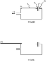
- a third system is shown in Figures 3A to 3E for information purposes only.
- the cover member (5) is adapted so that the water inlet (WI) may pass through the same wall of the steam chamber (3A) as the opening (4).
- the cover member (5) cooperates with the steam chamber (3A) so that, when the cover member is in the first position (P1), the cover member is disposed adjacent to the water inlet (WI).
- the cover member (5) is provided with an aperture (25) so that, when the cover member (5) is in the first position (P1), the aperture (25) aligns with the water inlet (WI) so as to allow for the passage of water through the aperture (25) and water inlet (WI) and into the steam chamber (3A).
- the cover member (5) is attached to the steam chamber (3A) by the same configuration of attachment elements (8,9) as described above, shown in Figure 3C .
- a fourth system is shown in Figure 4A , and an implementation of the fourth system according to a first embodiment of the invention is shown in Figure 4B .
- the system further comprises an outer housing (2), wherein the housing (2) may be configured to partly envelop the steam chamber (3A) so that at least one side of the steam chamber (3A) is covered by the housing (2).
- an opening (4A) is provided in the housing (2), the opening (4A) in the housing (2) being formed around the opening (4) in the steam chamber (3A), such that the opening (4A) in the housing communicates with the inside of the steam chamber (3A).
- the second attachment elements (9) are provided on the housing (2), with second elongate rails (9A) running parallel either side of the opening (4A) provided in the housing (2).
- the first attachment elements (8) are spaced apart corresponding to the spacing of the second attachment elements (9), such that the first ledges (8B) are in overlapping relation with the second ledges (9B) when the cover member (5) is in the first position (P1). Therefore, the cover member (5) can only be separated from the steam chamber (3A) by a sliding action of the cover member (5) relative to the housing (2) in a direction parallel to the attachment elements (8,9).
- the cover member (5) further comprises a steam outlet (6), the steam outlet (6) communicates with the inside of the steam chamber (3A) when the cover member (5) is in the first position (P1) to allow for the passage of steam through the steam outlet (6) and out of the steam chamber (3A).
- the cover member (5) comprises a silicon seal (7).
- the seal (7) is disposed around the opening (4) in the steam chamber (3A) and between the steam chamber (3A) and the cover member (5).
- a water inlet (not shown) is also provided to allow for the passage of water from a water tank (not shown) to the inside part of the steam chamber (3A).
- the water tank is formed integrally with the housing (2); in one such example, the water tank comprises a separate chamber formed in the housing (2) to store water and deliver water through the water inlet by any suitable means.
- the cover member (5) comprises a flat plate (16) wherein a plurality of apertures (6A) is provided in the plate (16) for delivering steam from the steam chamber (3A) when the device is operational.
- a surround (17) that is arranged to enclose the space between the housing (2) and the flat plate (16) when the cover member (5) is fitted to the housing (2).
- the surround (17) is a wall that extends around the outer edge of the plate (16) and is upstanding therefrom, so that the plate's (16) surface on which the surround (17) is disposed lies entirely within the confines of the surround (17).
- a bracket (18) formed integrally with the surround (17) and extending from the inner face of the surround (17) is provided for retaining the seal (7).
- the bracket (18) comprises a second wall (18A) that extends around the whole of the inner face of the surround (17) and into the region enclosed by the surround (17) to form an opening (4A) disposed opposite the flat plate (16).
- a U-shaped channel (18B) for retaining the seal (7) extends around the inner edge of the opening (4A).
- the seal (7) may be held in place by compression of the seal (7) material; this may be achieved by sizing the seal (7) so as to be marginally larger than the space within the U shaped channel (19). Alternatively, the seal (7) may be held in place by a suitable adhesive.
- a nozzle (7A) is formed integrally with the seal (7), and comprises a wall that extends around the opening (4A) provided in cover member (5) and into the surround (17), abutting the plate (16) to enclose the steam dispensing apertures (6). Therefore, with the cover member (5) disposed in the first position (P1), the nozzle (7A) fluidly couples the opening (4) formed in the steam chamber (3A) with the apertures (6A) formed in the plate (16) to provide a passage that directs the steam from the steam chamber (3A) to the apertures (6A) formed in the plate (16).
- the nozzle (7A) helps to prevent steam from condensing inside the surround (17) by minimising the surface area inside the surround (17) to which steam is exposed, thus reducing the risk of condensate passing through the apertures (6A) formed in the plate (16).
- the cover member (5) is configured so as to be removable from the housing (2) by a sliding action, as depicted in detail in Figures 5A and 5B , to provide the user with access to inside surfaces of the steam chamber (3) through the opening (4) provided in the steam chamber (3A).
- FIG. 6 An example cover member (5) is shown in Figure 6 .
- the first attachment elements (8) are disposed either side of the opening (4A) and are arranged parallel to allow the cover member (5) to be slideably engaged with the housing (2).
- the second attachment elements (9) conform to substantially the same shape as the first attachment elements (8) but are offset so as to lie within the first attachment elements (8) when the cover member is in the first position (P1).
- the first attachment element (8) is provided along one side of the upper edge of the surround (17) only, with the second attachment element (9) being provided along a corresponding side of the housing (2).
- the first attachment element (8) and second attachment element (9) are engaged such that the respective first and second ledges (8B, 9B) overlap; the opposite sides of the cover member (5) and housing (2) are then brought together and secured in place by a sprung catch (14) such that the cover member (5) is in the first position (P1).
- the sprung catch is a cantilevered tab (14) with a V-shaped bend (14A) disposed in the free end such that an element of the tab (14) extends from the main body of the tab (14).
- the tab may be made from steel or any suitable resiliently deformable material.
- the fixed end of the tab (14) is located permanently on the housing (2), with the free end protruding into overlapping relation with the top of the surround (17).
- the user is required to pull the two components apart by exerting a force not normally encountered during normal operation of the steam system (1), in this way the corresponding edge of the surround (17) is prevented from becoming separated from the housing (2) during normal operation of the steam system (1).
- alternative bend shapes can be envisaged that prevent separation of the cover member (5) from the housing (2) by a force acting to pull the two components apart
- a button (15), shown in Figure 8 may be provided to release the tab (14).
- the button (15) is moveably mounted to the housing (2) and mechanically coupled to the tab (14), such that when the button (15) is depressed the tab (14) is caused to disengage the cover member (5) so that the cover member (5) is free to move from the first position (P1) to the second position (P2).
- the button (15) is received in an opening formed in the housing (2) adjacent to the fixed end of tab (14).
- One end of the button (15), herein referred to as the operable end (15A), is disposed so as to protrude from the outer surface of the housing (2) when the tab (14) is in an initial position; the other end of the button (15), herein referred to as the distal end (15B), is in abutting relation with the tab (14).
- the button (15) is displaced and the distal end (15B) acts against the tab (14) to cause it to bend along its unfixed length from the initial position to a displaced position.
- the inherent elasticity of the material used to form the tab (14) causes the bending of the tab (14) to be reacted.
- the tab (14) moves from the displaced position to the initial position, acting on the distal end (15B) of the button to cause the button's operable end (15A) to be restored to a protruding position from the outer surface of the housing (2).
- the button (15) and the opening in which it is received are shaped so that the button (15) is constrained by the housing (2) when the tab (14) is in its initial position.
- this may be achieved by tapering the button (15) such that the distal end (15B) is larger in section than the operable end (15A), with the opening in the housing (2) having an internal surface that substantially matches the shape of the button's (15) exterior surface.
- the tab (14) acts against the button (15) so that the button (15) is held against the interior surface of the opening in the housing (2).
- the sprung catch (14) may alternatively be mounted to the wall portion (3B) and arranged so as to engage with the cover member (5) when the cover member (5) takes said first position (P1) so that the cover member (5) mounts directly to the wall portion (3B).
- the release button (15) may be moveably mounted on the wall portion (3B) and mechanically coupled to the sprung catch (14), such that when the release button (15) is actuated the sprung catch (14) is caused to disengage the cover member (5) to allow the cover member (5) to be detached from the wall portion (3B).
- the first and second attachment elements (8,9) are curved along their length to enable the cover member (5) to be attached to the housing (2) by rotation of the cover member (5) relative to the housing (2).
- An example cover member (5) with curved first attachment elements (8) is shown in Figure 9 .
- the cover member (5) is positioned relative to the housing (2) so that the upper edge of the surround (17) and the respective face of the housing (2) are aligned.
- the cover member (5) is rotated around a central axis (26) to cause it to be attached to the housing (2).
- the first and second attachment elements (8,9) have radius of curvature equal to their distance from the central axis (26).
- First and second attachment elements (8,9) are positioned such that, as the cover member (5) is attached to the housing (2), their respective first and second ledges (8B, 9B) are slid into abutting overlapping relation by rotation of the cover member (5) about the central axis (26).
- first attachment elements (8) have first ledges (8B) that are tapered so that the thickness of the ledge (8B) increases along the length of the ledge (8B), such that when first and second attachment elements (8,9) are moved into engagement, the rotation of the cover member (5) relative to the housing (2) causes the cover member (5) to be drawn towards the housing (2).
- first and second attachment elements (8,9) are moved into engagement, the rotation of the cover member (5) relative to the housing (2) causes the cover member (5) to be drawn towards the housing (2).
- the second ledge (9B) may also, or alternatively, be tapered so as to achieve the same effect.
- first and second attachment elements (8,9) provided on the wall portion (3B) in embodiments 1 to 3 may also be curved in the manner described hereinabove so that first and second attachment elements (8,9) may be moved into and out of engagement to attach and detach the cover member (5) to the wall portion (3B) by rotational movement of the cover member (5) relative to the wall portion (3B).
- the size and shape of the opening provided in the steam chamber (3A) is configured to provide access to the inside part of the steam chamber (3A), such that it can be manually cleaned of scale by the user; this may be achieved by rinsing or scraping the scale deposits away.
- Rinsing can be achieved by introducing water into the steam generator through the water inlet (WI), providing the advantage of delivering water to only the location where it is needed.
Landscapes
- Engineering & Computer Science (AREA)
- Physics & Mathematics (AREA)
- General Engineering & Computer Science (AREA)
- Mechanical Engineering (AREA)
- Thermal Sciences (AREA)
- Sustainable Development (AREA)
- Sustainable Energy (AREA)
- Life Sciences & Earth Sciences (AREA)
- Textile Engineering (AREA)
- Devices For Medical Bathing And Washing (AREA)
- Apparatus For Disinfection Or Sterilisation (AREA)
- Air Humidification (AREA)
- Cookers (AREA)
Claims (13)
- System (1) zum Erzeugen von Dampf, wobei das System umfasst:- eine Wandstruktur (3), die eine Dampfkammer (3A) bildet;- eine Öffnung (4), die in einem Wandabschnitt (3B) der Wandstruktur (3) ausgebildet ist; und- ein Abdeckelement (5), das mit dem Wandabschnitt (3B) so zusammenwirkt, dass das Abdeckelement (5) eine erste Position (P1), wo das Abdeckelement (5) die Öffnung (4) zudeckt, und eine zweite Position (P2), wo das Abdeckelement (5) die Öffnung aufdeckt (4), einnehmen kann;wobei die Öffnung (4) eine Querschnittsfläche aufweist, die mindestens 50 % der Querschnittsfläche des Wandabschnitts (3B) beträgt;
dadurch gekennzeichnet, dass das Abdeckelement (5) einen Dampfauslass (6) umfasst und dass das System (1) eine Düse (7A) umfasst, so dass dann, wenn das Abdeckelement (5) die erste Position (P1) einnimmt, der Dampfauslass (6) der Öffnung (4) zugewandt ist und die Düse (7A) die Öffnung (4) mit dem Dampfauslass (6) in Fluidverbindung bringt, um einen Kanal bereitzustellen, der dafür ausgelegt ist, den Dampf aus der Dampfkammer (3A) zum Dampfauslass (6) zu lenken. - System nach Anspruch 1, wobei eine Dichtung (7) zwischen dem Abdeckelement (5) und dem Wandabschnitt (3B) angeordnet ist.
- System nach einem der vorangehenden Ansprüche, ferner ein Gehäuse (2) umfassend, das die Dampfkammer (3A) zumindest zum Teil umgibt, und wobei das Abdeckelement (5) mit dem Gehäuse (2) zusammenwirkt, um das Abdeckelement (5) zwischen der ersten Position (P1) und der zweiten Position (P2) zu bewegen, wobei das Abdeckelement (5) ein erstes Befestigungselement (8) umfasst und das Gehäuse (2) ein zweites Befestigungselement (9) umfasst, wobei das erste Befestigungselement (8) und das zweite Befestigungselement (9) dafür ausgelegt sind, durch eine manuelle Betätigung des Abdeckelements (5) in Bezug auf den Wandabschnitt (3B) gegenseitig in Eingriff und außer Eingriff zu kommen.
- System nach Anspruch 3, wobei das erste Befestigungselement (8) eine erste längliche Schiene (8A) umfasst, die an dem Abdeckelement (5) angeordnet ist, und das zweite Befestigungselement (9) eine entsprechende zweite längliche Schiene (9A) umfasst, die an dem Gehäuse (2) angeordnet ist, wobei die erste Schiene eine erste Leiste (8B) umfasst und die zweite Schiene eine zweite Leiste (9B) umfasst, wobei sich die erste Leiste (8B) und die zweite Leiste (9B) zumindest entlang eines Abschnitts der entsprechenden Schiene erstrecken, so dass, wenn das Abdeckelement (5) die erste Position (P1) einnimmt, die entsprechenden Leisten einander überlappen und aneinander anstoßen.
- System nach einem der Ansprüche 3 bis 4, wobei das Gehäuse (2) ein weiteres zweites Befestigungselement aufweist, das einen Schnappverschluss (14) umfasst, der so angeordnet ist, dass er in das Abdeckelement (5) eingreift, wenn das Abdeckelement (5) die erste Position (P1) einnimmt.
- System nach Anspruch 5, einen Auslöseknopf (15) umfassend, der bewegbar an dem Gehäuse (2) montiert und mechanisch mit dem Schnappverschluss (14) gekoppelt ist, so dass dann, wenn der Auslöseknopf (15) betätigt wird, bewirkt wird, dass der Auslöseknopf (14) das Abdeckelement (5) freigibt, so dass sich das Abdeckelement (5) ungehindert aus der ersten Position (P1) zur zweiten Position (P2) bewegen kann.
- System nach Anspruch 5 oder Anspruch 6, soweit diese von Anspruch 4 abhängen, wobei sich die erste längliche Schiene (8A) entlang einer Seite des Abdeckelements (5) erstreckt und sich die zweite längliche Schiene (9A) entlang einer entsprechenden Seite des Gehäuses (2) erstreckt, wobei der Schnappverschluss (14) so an dem Gehäuse (2) angeordnet ist, dass er die entgegengesetzten Seite des Abdeckelements (5) mit der Seite des Abdeckelements (5), wo die erste längliche Schiene (8A) angeordnet ist, in Eingriff bringt.
- System nach Anspruch 4, wobei das Abdeckelement (5) in Bezug auf das Gehäuse (2) verschiebbar ist, um das erste Befestigungselement (8) und das zweite Befestigungselement (9) in und außer Eingriff zu bringen, um das Abdeckelement (5) am Gehäuse (2) zu befestigen bzw. von diesem zu lösen.
- System nach Anspruch 3 oder nach den Ansprüchen 4 bis 8, soweit diese von Anspruch 3 abhängen, wobei mindestens eines von dem ersten Befestigungselement (8) und dem zweiten Befestigungselement (9) elastisch verformbar ist, um einen Eingriff mit und eine Freigabe von dem oder jedem anderen Befestigungselement zu ermöglichen.
- System nach einem der vorangehenden Ansprüche 3 bis 9, wobei das Abdeckelement (5) ohne die Verwendung eines Werkzeugs von der ersten Position (P1) zur zweiten Position (P2) manuell von dem Gehäuse (2) gelöst werden kann und von der zweiten Position (P2) zur ersten Position (P1) manuell an dem Gehäuse (2) befestigt werden kann.
- System nach Anspruch 4, das so ausgelegt ist, dass die erste längliche Schiene (8A) und die entsprechende zweite längliche Schiene (9A) ihrer Länge nach gekrümmt sind, so dass sie in und außer Eingriff bewegt werden können, um durch eine Drehbewegung des Abdeckelements (5) in Bezug auf das Gehäuse (2) das Abdeckelement (5) am Gehäuse (2) zu befestigen und von diesem zu lösen.
- System nach Anspruch 11, wobei mindestens eine von der ersten länglichen Schiene (8A) und der zweiten länglichen Schiene (9A) derart abgeschrägt ist, dass die Dicke der Schiene entlang der Länge der Schiene zunimmt, so dass dann, wenn die länglichen Schienen (8A, 9A) in Eingriff bewegt werden, die Drehbewegung des Abdeckelements (5) in Bezug auf das Gehäuse (2) bewirkt, dass das Abdeckelement (5) zum Wandabschnitt (3B) gezogen wird.
- System nach Anspruch 12, wobei das Abdeckelement (5) so angepasst ist, dass ein Wassereinlass (WI) durch dieselbe Wand der Dampfkammer (3A) wie die Öffnung (4) verlaufen kann.
Applications Claiming Priority (2)
| Application Number | Priority Date | Filing Date | Title |
|---|---|---|---|
| EP15152225 | 2015-01-23 | ||
| PCT/EP2016/051392 WO2016116631A1 (en) | 2015-01-23 | 2016-01-22 | Steam generating system with detachable cover |
Publications (2)
| Publication Number | Publication Date |
|---|---|
| EP3247939A1 EP3247939A1 (de) | 2017-11-29 |
| EP3247939B1 true EP3247939B1 (de) | 2020-09-30 |
Family
ID=52358694
Family Applications (1)
| Application Number | Title | Priority Date | Filing Date |
|---|---|---|---|
| EP16701475.2A Active EP3247939B1 (de) | 2015-01-23 | 2016-01-22 | Dampferzeugungssystem mit abnehmbarer abdeckung |
Country Status (8)
| Country | Link |
|---|---|
| US (1) | US20170370572A1 (de) |
| EP (1) | EP3247939B1 (de) |
| JP (1) | JP2018503052A (de) |
| CN (1) | CN107208878B (de) |
| BR (1) | BR112017015494A2 (de) |
| PL (1) | PL3247939T3 (de) |
| RU (1) | RU2707785C2 (de) |
| WO (1) | WO2016116631A1 (de) |
Family Cites Families (18)
| Publication number | Priority date | Publication date | Assignee | Title |
|---|---|---|---|---|
| US3538306A (en) * | 1968-01-22 | 1970-11-03 | Champion Spark Plug Co | Vaporizer |
| US3593441A (en) * | 1969-12-15 | 1971-07-20 | Gen Electric | Steam iron metallic sealing structure |
| JPS5216922Y2 (de) * | 1971-12-13 | 1977-04-16 | ||
| JPS53106501U (de) * | 1977-01-31 | 1978-08-26 | ||
| US4243870A (en) * | 1978-02-09 | 1981-01-06 | Champion Spark Plug Company | Vaporizer with electrode housing interlock |
| SU785591A1 (ru) * | 1979-02-16 | 1980-12-07 | За витель ФШи1 yu::. | Парогенерирующее устройство |
| GB8909510D0 (en) * | 1989-04-29 | 1989-06-14 | Earlex Ltd | Steam generator |
| US5748836A (en) * | 1995-01-13 | 1998-05-05 | Sunbeam Products, Inc. | Locking mechanism for vaporizer electrode housing utilizing electrical plug prong as key |
| US6243535B1 (en) * | 1997-02-14 | 2001-06-05 | Ecovap S.A. | Steam generator |
| FR2770077B1 (fr) * | 1997-10-17 | 2002-03-01 | Moulinex Sa | Chaudiere pour appareil electromenager et appareil electromenager comportant une telle chaudiere |
| US6226904B1 (en) * | 1999-09-01 | 2001-05-08 | Hamilton Beach/Proctor-Silex, Inc. | Burn guard electric iron soleplate |
| WO2003085188A1 (en) * | 2002-04-08 | 2003-10-16 | Termozeta S.P.A. | Iron and plate for an iron |
| JP4211690B2 (ja) * | 2004-06-14 | 2009-01-21 | パナソニック電工株式会社 | スチーム式美容器 |
| FR2904683B1 (fr) * | 2006-08-03 | 2008-10-24 | Seb Sa | Appreil electromenager comportant une cuve dans laquelle de l'eau est portee a ebullition et des moyens pour evacuer le tartre |
| CN102112679B (zh) * | 2008-07-31 | 2012-10-03 | 皇家飞利浦电子股份有限公司 | 蒸汽熨斗 |
| FR2954360B1 (fr) * | 2009-12-17 | 2014-06-27 | Seb Sa | Appareil de repassage a la vapeur comportant une brosse de defroissage |
| AU2011224948B2 (en) * | 2010-03-12 | 2014-04-24 | Lg Electronics Inc. | Steam generator and washing machine having the same |
| CN105229376B (zh) * | 2013-05-14 | 2017-04-19 | 阿尔弗雷德·凯驰两合公司 | 蒸汽发生器 |
-
2016
- 2016-01-22 EP EP16701475.2A patent/EP3247939B1/de active Active
- 2016-01-22 BR BR112017015494A patent/BR112017015494A2/pt not_active Application Discontinuation
- 2016-01-22 RU RU2017129255A patent/RU2707785C2/ru active
- 2016-01-22 US US15/544,560 patent/US20170370572A1/en not_active Abandoned
- 2016-01-22 CN CN201680006921.6A patent/CN107208878B/zh active Active
- 2016-01-22 JP JP2017533945A patent/JP2018503052A/ja active Pending
- 2016-01-22 PL PL16701475.2T patent/PL3247939T3/pl unknown
- 2016-01-22 WO PCT/EP2016/051392 patent/WO2016116631A1/en not_active Ceased
Non-Patent Citations (1)
| Title |
|---|
| None * |
Also Published As
| Publication number | Publication date |
|---|---|
| BR112017015494A2 (pt) | 2018-01-30 |
| WO2016116631A1 (en) | 2016-07-28 |
| JP2018503052A (ja) | 2018-02-01 |
| CN107208878A (zh) | 2017-09-26 |
| PL3247939T3 (pl) | 2021-03-22 |
| CN107208878B (zh) | 2020-08-21 |
| EP3247939A1 (de) | 2017-11-29 |
| RU2707785C2 (ru) | 2019-11-29 |
| RU2017129255A (ru) | 2019-02-25 |
| US20170370572A1 (en) | 2017-12-28 |
| RU2017129255A3 (de) | 2019-06-20 |
Similar Documents
| Publication | Publication Date | Title |
|---|---|---|
| US5552578A (en) | Oven with excess steam treatment device | |
| EP3024970B1 (de) | Vorrichtung zur dampferzeugung | |
| US10330308B2 (en) | Apparatus for generating steam | |
| KR102231032B1 (ko) | 전기밥솥 | |
| JP2014504852A5 (de) | ||
| JP4789428B2 (ja) | 物質、特に食品を熱処理するための装置 | |
| RU2606317C2 (ru) | Утюг | |
| EP3247939B1 (de) | Dampferzeugungssystem mit abnehmbarer abdeckung | |
| AU2014202648A1 (en) | Steam clothes ironing device containing a clothes iron | |
| RU2017109875A (ru) | Рабочая часть парового утюга | |
| EP3377814B1 (de) | Vorrichtung zur dampferzeugung mit einem wiegebehälter | |
| EP3631077B1 (de) | Bügeleisen | |
| US20210088222A1 (en) | Cooker | |
| AU2014202647A1 (en) | Steam ironing device | |
| NL8601186A (nl) | Werkwijze voor het sluiten van een verdampingskamer van een stoomstrijkijzer. | |
| EP3999681B1 (de) | Behälter zum auffangen des waschwassers eines bügeleisens | |
| CN110645557B (zh) | 一种蒸汽分离件、蒸汽发生装置及蒸烤设备 | |
| CN206189164U (zh) | 熨斗及熨斗的背盖 | |
| JP6169031B2 (ja) | 蒸気回収器及び加熱機器 | |
| CN215272086U (zh) | 一种用于烹饪设备的蒸汽冷凝结构及烹饪设备 | |
| CN210831936U (zh) | 一种蒸汽分离件、蒸汽发生装置及蒸烤设备 | |
| CN109699182A (zh) | 无线蒸汽生产装置 | |
| EP3446046B1 (de) | Kessel | |
| DE502007003252D1 (de) | Dampfbügeleisen | |
| CN102517864B (zh) | 一种防滴水的挂烫机蒸汽刷结构 |
Legal Events
| Date | Code | Title | Description |
|---|---|---|---|
| STAA | Information on the status of an ep patent application or granted ep patent |
Free format text: STATUS: THE INTERNATIONAL PUBLICATION HAS BEEN MADE |
|
| PUAI | Public reference made under article 153(3) epc to a published international application that has entered the european phase |
Free format text: ORIGINAL CODE: 0009012 |
|
| STAA | Information on the status of an ep patent application or granted ep patent |
Free format text: STATUS: REQUEST FOR EXAMINATION WAS MADE |
|
| 17P | Request for examination filed |
Effective date: 20170823 |
|
| AK | Designated contracting states |
Kind code of ref document: A1 Designated state(s): AL AT BE BG CH CY CZ DE DK EE ES FI FR GB GR HR HU IE IS IT LI LT LU LV MC MK MT NL NO PL PT RO RS SE SI SK SM TR |
|
| AX | Request for extension of the european patent |
Extension state: BA ME |
|
| DAV | Request for validation of the european patent (deleted) | ||
| DAX | Request for extension of the european patent (deleted) | ||
| RAP1 | Party data changed (applicant data changed or rights of an application transferred) |
Owner name: KONINKLIJKE PHILIPS N.V. |
|
| GRAP | Despatch of communication of intention to grant a patent |
Free format text: ORIGINAL CODE: EPIDOSNIGR1 |
|
| STAA | Information on the status of an ep patent application or granted ep patent |
Free format text: STATUS: GRANT OF PATENT IS INTENDED |
|
| INTG | Intention to grant announced |
Effective date: 20200417 |
|
| RIN1 | Information on inventor provided before grant (corrected) |
Inventor name: BOERSMA, JOLDERT, MARIA Inventor name: VAN AKEN, TIMOTHEUS, JOHANNES, MARIA Inventor name: BRUGGINK, WILHELMUS, HENDRIKUS, MARIA Inventor name: KOOIJKER, KLAAS |
|
| GRAS | Grant fee paid |
Free format text: ORIGINAL CODE: EPIDOSNIGR3 |
|
| GRAA | (expected) grant |
Free format text: ORIGINAL CODE: 0009210 |
|
| STAA | Information on the status of an ep patent application or granted ep patent |
Free format text: STATUS: THE PATENT HAS BEEN GRANTED |
|
| AK | Designated contracting states |
Kind code of ref document: B1 Designated state(s): AL AT BE BG CH CY CZ DE DK EE ES FI FR GB GR HR HU IE IS IT LI LT LU LV MC MK MT NL NO PL PT RO RS SE SI SK SM TR |
|
| REG | Reference to a national code |
Ref country code: GB Ref legal event code: FG4D Ref country code: CH Ref legal event code: EP |
|
| REG | Reference to a national code |
Ref country code: AT Ref legal event code: REF Ref document number: 1319159 Country of ref document: AT Kind code of ref document: T Effective date: 20201015 |
|
| REG | Reference to a national code |
Ref country code: DE Ref legal event code: R096 Ref document number: 602016044890 Country of ref document: DE |
|
| REG | Reference to a national code |
Ref country code: IE Ref legal event code: FG4D |
|
| REG | Reference to a national code |
Ref country code: SE Ref legal event code: TRGR |
|
| PG25 | Lapsed in a contracting state [announced via postgrant information from national office to epo] |
Ref country code: BG Free format text: LAPSE BECAUSE OF FAILURE TO SUBMIT A TRANSLATION OF THE DESCRIPTION OR TO PAY THE FEE WITHIN THE PRESCRIBED TIME-LIMIT Effective date: 20201230 Ref country code: NO Free format text: LAPSE BECAUSE OF FAILURE TO SUBMIT A TRANSLATION OF THE DESCRIPTION OR TO PAY THE FEE WITHIN THE PRESCRIBED TIME-LIMIT Effective date: 20201230 Ref country code: HR Free format text: LAPSE BECAUSE OF FAILURE TO SUBMIT A TRANSLATION OF THE DESCRIPTION OR TO PAY THE FEE WITHIN THE PRESCRIBED TIME-LIMIT Effective date: 20200930 Ref country code: FI Free format text: LAPSE BECAUSE OF FAILURE TO SUBMIT A TRANSLATION OF THE DESCRIPTION OR TO PAY THE FEE WITHIN THE PRESCRIBED TIME-LIMIT Effective date: 20200930 Ref country code: GR Free format text: LAPSE BECAUSE OF FAILURE TO SUBMIT A TRANSLATION OF THE DESCRIPTION OR TO PAY THE FEE WITHIN THE PRESCRIBED TIME-LIMIT Effective date: 20201231 |
|
| REG | Reference to a national code |
Ref country code: AT Ref legal event code: MK05 Ref document number: 1319159 Country of ref document: AT Kind code of ref document: T Effective date: 20200930 |
|
| PG25 | Lapsed in a contracting state [announced via postgrant information from national office to epo] |
Ref country code: RS Free format text: LAPSE BECAUSE OF FAILURE TO SUBMIT A TRANSLATION OF THE DESCRIPTION OR TO PAY THE FEE WITHIN THE PRESCRIBED TIME-LIMIT Effective date: 20200930 Ref country code: LV Free format text: LAPSE BECAUSE OF FAILURE TO SUBMIT A TRANSLATION OF THE DESCRIPTION OR TO PAY THE FEE WITHIN THE PRESCRIBED TIME-LIMIT Effective date: 20200930 |
|
| REG | Reference to a national code |
Ref country code: NL Ref legal event code: MP Effective date: 20200930 |
|
| REG | Reference to a national code |
Ref country code: LT Ref legal event code: MG4D |
|
| PG25 | Lapsed in a contracting state [announced via postgrant information from national office to epo] |
Ref country code: CZ Free format text: LAPSE BECAUSE OF FAILURE TO SUBMIT A TRANSLATION OF THE DESCRIPTION OR TO PAY THE FEE WITHIN THE PRESCRIBED TIME-LIMIT Effective date: 20200930 Ref country code: SM Free format text: LAPSE BECAUSE OF FAILURE TO SUBMIT A TRANSLATION OF THE DESCRIPTION OR TO PAY THE FEE WITHIN THE PRESCRIBED TIME-LIMIT Effective date: 20200930 Ref country code: PT Free format text: LAPSE BECAUSE OF FAILURE TO SUBMIT A TRANSLATION OF THE DESCRIPTION OR TO PAY THE FEE WITHIN THE PRESCRIBED TIME-LIMIT Effective date: 20210201 Ref country code: RO Free format text: LAPSE BECAUSE OF FAILURE TO SUBMIT A TRANSLATION OF THE DESCRIPTION OR TO PAY THE FEE WITHIN THE PRESCRIBED TIME-LIMIT Effective date: 20200930 Ref country code: LT Free format text: LAPSE BECAUSE OF FAILURE TO SUBMIT A TRANSLATION OF THE DESCRIPTION OR TO PAY THE FEE WITHIN THE PRESCRIBED TIME-LIMIT Effective date: 20200930 Ref country code: NL Free format text: LAPSE BECAUSE OF FAILURE TO SUBMIT A TRANSLATION OF THE DESCRIPTION OR TO PAY THE FEE WITHIN THE PRESCRIBED TIME-LIMIT Effective date: 20200930 Ref country code: EE Free format text: LAPSE BECAUSE OF FAILURE TO SUBMIT A TRANSLATION OF THE DESCRIPTION OR TO PAY THE FEE WITHIN THE PRESCRIBED TIME-LIMIT Effective date: 20200930 |
|
| PG25 | Lapsed in a contracting state [announced via postgrant information from national office to epo] |
Ref country code: IS Free format text: LAPSE BECAUSE OF FAILURE TO SUBMIT A TRANSLATION OF THE DESCRIPTION OR TO PAY THE FEE WITHIN THE PRESCRIBED TIME-LIMIT Effective date: 20210130 Ref country code: AL Free format text: LAPSE BECAUSE OF FAILURE TO SUBMIT A TRANSLATION OF THE DESCRIPTION OR TO PAY THE FEE WITHIN THE PRESCRIBED TIME-LIMIT Effective date: 20200930 Ref country code: AT Free format text: LAPSE BECAUSE OF FAILURE TO SUBMIT A TRANSLATION OF THE DESCRIPTION OR TO PAY THE FEE WITHIN THE PRESCRIBED TIME-LIMIT Effective date: 20200930 Ref country code: ES Free format text: LAPSE BECAUSE OF FAILURE TO SUBMIT A TRANSLATION OF THE DESCRIPTION OR TO PAY THE FEE WITHIN THE PRESCRIBED TIME-LIMIT Effective date: 20200930 |
|
| PG25 | Lapsed in a contracting state [announced via postgrant information from national office to epo] |
Ref country code: SK Free format text: LAPSE BECAUSE OF FAILURE TO SUBMIT A TRANSLATION OF THE DESCRIPTION OR TO PAY THE FEE WITHIN THE PRESCRIBED TIME-LIMIT Effective date: 20200930 |
|
| REG | Reference to a national code |
Ref country code: DE Ref legal event code: R097 Ref document number: 602016044890 Country of ref document: DE |
|
| REG | Reference to a national code |
Ref country code: DE Ref legal event code: R119 Ref document number: 602016044890 Country of ref document: DE |
|
| PLBE | No opposition filed within time limit |
Free format text: ORIGINAL CODE: 0009261 |
|
| STAA | Information on the status of an ep patent application or granted ep patent |
Free format text: STATUS: NO OPPOSITION FILED WITHIN TIME LIMIT |
|
| PG25 | Lapsed in a contracting state [announced via postgrant information from national office to epo] |
Ref country code: DK Free format text: LAPSE BECAUSE OF FAILURE TO SUBMIT A TRANSLATION OF THE DESCRIPTION OR TO PAY THE FEE WITHIN THE PRESCRIBED TIME-LIMIT Effective date: 20200930 Ref country code: MC Free format text: LAPSE BECAUSE OF FAILURE TO SUBMIT A TRANSLATION OF THE DESCRIPTION OR TO PAY THE FEE WITHIN THE PRESCRIBED TIME-LIMIT Effective date: 20200930 |
|
| REG | Reference to a national code |
Ref country code: CH Ref legal event code: PL |
|
| 26N | No opposition filed |
Effective date: 20210701 |
|
| GBPC | Gb: european patent ceased through non-payment of renewal fee |
Effective date: 20210122 |
|
| PG25 | Lapsed in a contracting state [announced via postgrant information from national office to epo] |
Ref country code: LU Free format text: LAPSE BECAUSE OF NON-PAYMENT OF DUE FEES Effective date: 20210122 |
|
| REG | Reference to a national code |
Ref country code: BE Ref legal event code: MM Effective date: 20210131 |
|
| PG25 | Lapsed in a contracting state [announced via postgrant information from national office to epo] |
Ref country code: IT Free format text: LAPSE BECAUSE OF FAILURE TO SUBMIT A TRANSLATION OF THE DESCRIPTION OR TO PAY THE FEE WITHIN THE PRESCRIBED TIME-LIMIT Effective date: 20200930 |
|
| PG25 | Lapsed in a contracting state [announced via postgrant information from national office to epo] |
Ref country code: CH Free format text: LAPSE BECAUSE OF NON-PAYMENT OF DUE FEES Effective date: 20210131 Ref country code: DE Free format text: LAPSE BECAUSE OF NON-PAYMENT OF DUE FEES Effective date: 20210803 Ref country code: SI Free format text: LAPSE BECAUSE OF FAILURE TO SUBMIT A TRANSLATION OF THE DESCRIPTION OR TO PAY THE FEE WITHIN THE PRESCRIBED TIME-LIMIT Effective date: 20200930 Ref country code: LI Free format text: LAPSE BECAUSE OF NON-PAYMENT OF DUE FEES Effective date: 20210131 Ref country code: GB Free format text: LAPSE BECAUSE OF NON-PAYMENT OF DUE FEES Effective date: 20210122 |
|
| PG25 | Lapsed in a contracting state [announced via postgrant information from national office to epo] |
Ref country code: IE Free format text: LAPSE BECAUSE OF NON-PAYMENT OF DUE FEES Effective date: 20210122 |
|
| PG25 | Lapsed in a contracting state [announced via postgrant information from national office to epo] |
Ref country code: IS Free format text: LAPSE BECAUSE OF FAILURE TO SUBMIT A TRANSLATION OF THE DESCRIPTION OR TO PAY THE FEE WITHIN THE PRESCRIBED TIME-LIMIT Effective date: 20210130 |
|
| PG25 | Lapsed in a contracting state [announced via postgrant information from national office to epo] |
Ref country code: BE Free format text: LAPSE BECAUSE OF NON-PAYMENT OF DUE FEES Effective date: 20210131 |
|
| PGFP | Annual fee paid to national office [announced via postgrant information from national office to epo] |
Ref country code: FR Payment date: 20230124 Year of fee payment: 8 |
|
| PG25 | Lapsed in a contracting state [announced via postgrant information from national office to epo] |
Ref country code: HU Free format text: LAPSE BECAUSE OF FAILURE TO SUBMIT A TRANSLATION OF THE DESCRIPTION OR TO PAY THE FEE WITHIN THE PRESCRIBED TIME-LIMIT; INVALID AB INITIO Effective date: 20160122 |
|
| PGFP | Annual fee paid to national office [announced via postgrant information from national office to epo] |
Ref country code: SE Payment date: 20230124 Year of fee payment: 8 Ref country code: PL Payment date: 20230111 Year of fee payment: 8 |
|
| PG25 | Lapsed in a contracting state [announced via postgrant information from national office to epo] |
Ref country code: CY Free format text: LAPSE BECAUSE OF FAILURE TO SUBMIT A TRANSLATION OF THE DESCRIPTION OR TO PAY THE FEE WITHIN THE PRESCRIBED TIME-LIMIT Effective date: 20200930 |
|
| P01 | Opt-out of the competence of the unified patent court (upc) registered |
Effective date: 20230530 |
|
| PG25 | Lapsed in a contracting state [announced via postgrant information from national office to epo] |
Ref country code: MK Free format text: LAPSE BECAUSE OF FAILURE TO SUBMIT A TRANSLATION OF THE DESCRIPTION OR TO PAY THE FEE WITHIN THE PRESCRIBED TIME-LIMIT Effective date: 20200930 |
|
| PG25 | Lapsed in a contracting state [announced via postgrant information from national office to epo] |
Ref country code: TR Free format text: LAPSE BECAUSE OF FAILURE TO SUBMIT A TRANSLATION OF THE DESCRIPTION OR TO PAY THE FEE WITHIN THE PRESCRIBED TIME-LIMIT Effective date: 20200930 |
|
| REG | Reference to a national code |
Ref country code: SE Ref legal event code: EUG |
|
| PG25 | Lapsed in a contracting state [announced via postgrant information from national office to epo] |
Ref country code: MT Free format text: LAPSE BECAUSE OF FAILURE TO SUBMIT A TRANSLATION OF THE DESCRIPTION OR TO PAY THE FEE WITHIN THE PRESCRIBED TIME-LIMIT Effective date: 20200930 |
|
| PG25 | Lapsed in a contracting state [announced via postgrant information from national office to epo] |
Ref country code: FR Free format text: LAPSE BECAUSE OF NON-PAYMENT OF DUE FEES Effective date: 20240131 |
|
| PG25 | Lapsed in a contracting state [announced via postgrant information from national office to epo] |
Ref country code: FR Free format text: LAPSE BECAUSE OF NON-PAYMENT OF DUE FEES Effective date: 20240131 |
|
| PG25 | Lapsed in a contracting state [announced via postgrant information from national office to epo] |
Ref country code: SE Free format text: LAPSE BECAUSE OF NON-PAYMENT OF DUE FEES Effective date: 20240123 |