EP3247963B1 - Système d'accumulation d'énergie thermique à haute température, procédé de construction et procédé d'exploitation dudit système d'accumulation - Google Patents
Système d'accumulation d'énergie thermique à haute température, procédé de construction et procédé d'exploitation dudit système d'accumulation Download PDFInfo
- Publication number
- EP3247963B1 EP3247963B1 EP15870420.5A EP15870420A EP3247963B1 EP 3247963 B1 EP3247963 B1 EP 3247963B1 EP 15870420 A EP15870420 A EP 15870420A EP 3247963 B1 EP3247963 B1 EP 3247963B1
- Authority
- EP
- European Patent Office
- Prior art keywords
- elements
- storage
- thermal energy
- cassettes
- concrete
- Prior art date
- Legal status (The legal status is an assumption and is not a legal conclusion. Google has not performed a legal analysis and makes no representation as to the accuracy of the status listed.)
- Active
Links
Images



Classifications
-
- F—MECHANICAL ENGINEERING; LIGHTING; HEATING; WEAPONS; BLASTING
- F28—HEAT EXCHANGE IN GENERAL
- F28D—HEAT-EXCHANGE APPARATUS, NOT PROVIDED FOR IN ANOTHER SUBCLASS, IN WHICH THE HEAT-EXCHANGE MEDIA DO NOT COME INTO DIRECT CONTACT
- F28D20/00—Heat storage plants or apparatus in general; Regenerative heat-exchange apparatus not covered by groups F28D17/00 or F28D19/00
-
- F—MECHANICAL ENGINEERING; LIGHTING; HEATING; WEAPONS; BLASTING
- F28—HEAT EXCHANGE IN GENERAL
- F28D—HEAT-EXCHANGE APPARATUS, NOT PROVIDED FOR IN ANOTHER SUBCLASS, IN WHICH THE HEAT-EXCHANGE MEDIA DO NOT COME INTO DIRECT CONTACT
- F28D20/00—Heat storage plants or apparatus in general; Regenerative heat-exchange apparatus not covered by groups F28D17/00 or F28D19/00
- F28D20/0056—Heat storage plants or apparatus in general; Regenerative heat-exchange apparatus not covered by groups F28D17/00 or F28D19/00 using solid heat storage material
-
- F—MECHANICAL ENGINEERING; LIGHTING; HEATING; WEAPONS; BLASTING
- F28—HEAT EXCHANGE IN GENERAL
- F28D—HEAT-EXCHANGE APPARATUS, NOT PROVIDED FOR IN ANOTHER SUBCLASS, IN WHICH THE HEAT-EXCHANGE MEDIA DO NOT COME INTO DIRECT CONTACT
- F28D20/00—Heat storage plants or apparatus in general; Regenerative heat-exchange apparatus not covered by groups F28D17/00 or F28D19/00
- F28D20/02—Heat storage plants or apparatus in general; Regenerative heat-exchange apparatus not covered by groups F28D17/00 or F28D19/00 using latent heat
-
- F—MECHANICAL ENGINEERING; LIGHTING; HEATING; WEAPONS; BLASTING
- F28—HEAT EXCHANGE IN GENERAL
- F28D—HEAT-EXCHANGE APPARATUS, NOT PROVIDED FOR IN ANOTHER SUBCLASS, IN WHICH THE HEAT-EXCHANGE MEDIA DO NOT COME INTO DIRECT CONTACT
- F28D1/00—Heat-exchange apparatus having stationary conduit assemblies for one heat-exchange medium only, the media being in contact with different sides of the conduit wall, in which the other heat-exchange medium is a large body of fluid, e.g. domestic or motor car radiators
- F28D1/02—Heat-exchange apparatus having stationary conduit assemblies for one heat-exchange medium only, the media being in contact with different sides of the conduit wall, in which the other heat-exchange medium is a large body of fluid, e.g. domestic or motor car radiators with heat-exchange conduits immersed in the body of fluid
- F28D1/04—Heat-exchange apparatus having stationary conduit assemblies for one heat-exchange medium only, the media being in contact with different sides of the conduit wall, in which the other heat-exchange medium is a large body of fluid, e.g. domestic or motor car radiators with heat-exchange conduits immersed in the body of fluid with tubular conduits
- F28D1/047—Heat-exchange apparatus having stationary conduit assemblies for one heat-exchange medium only, the media being in contact with different sides of the conduit wall, in which the other heat-exchange medium is a large body of fluid, e.g. domestic or motor car radiators with heat-exchange conduits immersed in the body of fluid with tubular conduits the conduits being bent, e.g. in a serpentine or zig-zag
- F28D1/0477—Heat-exchange apparatus having stationary conduit assemblies for one heat-exchange medium only, the media being in contact with different sides of the conduit wall, in which the other heat-exchange medium is a large body of fluid, e.g. domestic or motor car radiators with heat-exchange conduits immersed in the body of fluid with tubular conduits the conduits being bent, e.g. in a serpentine or zig-zag the conduits being bent in a serpentine or zig-zag
-
- F—MECHANICAL ENGINEERING; LIGHTING; HEATING; WEAPONS; BLASTING
- F28—HEAT EXCHANGE IN GENERAL
- F28D—HEAT-EXCHANGE APPARATUS, NOT PROVIDED FOR IN ANOTHER SUBCLASS, IN WHICH THE HEAT-EXCHANGE MEDIA DO NOT COME INTO DIRECT CONTACT
- F28D20/00—Heat storage plants or apparatus in general; Regenerative heat-exchange apparatus not covered by groups F28D17/00 or F28D19/00
- F28D20/0034—Heat storage plants or apparatus in general; Regenerative heat-exchange apparatus not covered by groups F28D17/00 or F28D19/00 using liquid heat storage material
-
- F—MECHANICAL ENGINEERING; LIGHTING; HEATING; WEAPONS; BLASTING
- F28—HEAT EXCHANGE IN GENERAL
- F28D—HEAT-EXCHANGE APPARATUS, NOT PROVIDED FOR IN ANOTHER SUBCLASS, IN WHICH THE HEAT-EXCHANGE MEDIA DO NOT COME INTO DIRECT CONTACT
- F28D20/00—Heat storage plants or apparatus in general; Regenerative heat-exchange apparatus not covered by groups F28D17/00 or F28D19/00
- F28D20/02—Heat storage plants or apparatus in general; Regenerative heat-exchange apparatus not covered by groups F28D17/00 or F28D19/00 using latent heat
- F28D20/021—Heat storage plants or apparatus in general; Regenerative heat-exchange apparatus not covered by groups F28D17/00 or F28D19/00 using latent heat the latent heat storage material and the heat-exchanging means being enclosed in one container
-
- F—MECHANICAL ENGINEERING; LIGHTING; HEATING; WEAPONS; BLASTING
- F28—HEAT EXCHANGE IN GENERAL
- F28D—HEAT-EXCHANGE APPARATUS, NOT PROVIDED FOR IN ANOTHER SUBCLASS, IN WHICH THE HEAT-EXCHANGE MEDIA DO NOT COME INTO DIRECT CONTACT
- F28D20/00—Heat storage plants or apparatus in general; Regenerative heat-exchange apparatus not covered by groups F28D17/00 or F28D19/00
- F28D2020/0004—Particular heat storage apparatus
- F28D2020/0021—Particular heat storage apparatus the heat storage material being enclosed in loose or stacked elements
-
- F—MECHANICAL ENGINEERING; LIGHTING; HEATING; WEAPONS; BLASTING
- F28—HEAT EXCHANGE IN GENERAL
- F28D—HEAT-EXCHANGE APPARATUS, NOT PROVIDED FOR IN ANOTHER SUBCLASS, IN WHICH THE HEAT-EXCHANGE MEDIA DO NOT COME INTO DIRECT CONTACT
- F28D20/00—Heat storage plants or apparatus in general; Regenerative heat-exchange apparatus not covered by groups F28D17/00 or F28D19/00
- F28D2020/0065—Details, e.g. particular heat storage tanks, auxiliary members within tanks
- F28D2020/0078—Heat exchanger arrangements
-
- F—MECHANICAL ENGINEERING; LIGHTING; HEATING; WEAPONS; BLASTING
- F28—HEAT EXCHANGE IN GENERAL
- F28D—HEAT-EXCHANGE APPARATUS, NOT PROVIDED FOR IN ANOTHER SUBCLASS, IN WHICH THE HEAT-EXCHANGE MEDIA DO NOT COME INTO DIRECT CONTACT
- F28D20/00—Heat storage plants or apparatus in general; Regenerative heat-exchange apparatus not covered by groups F28D17/00 or F28D19/00
- F28D2020/0065—Details, e.g. particular heat storage tanks, auxiliary members within tanks
- F28D2020/0082—Multiple tanks arrangements, e.g. adjacent tanks, tank in tank
-
- Y—GENERAL TAGGING OF NEW TECHNOLOGICAL DEVELOPMENTS; GENERAL TAGGING OF CROSS-SECTIONAL TECHNOLOGIES SPANNING OVER SEVERAL SECTIONS OF THE IPC; TECHNICAL SUBJECTS COVERED BY FORMER USPC CROSS-REFERENCE ART COLLECTIONS [XRACs] AND DIGESTS
- Y02—TECHNOLOGIES OR APPLICATIONS FOR MITIGATION OR ADAPTATION AGAINST CLIMATE CHANGE
- Y02E—REDUCTION OF GREENHOUSE GAS [GHG] EMISSIONS, RELATED TO ENERGY GENERATION, TRANSMISSION OR DISTRIBUTION
- Y02E60/00—Enabling technologies; Technologies with a potential or indirect contribution to GHG emissions mitigation
- Y02E60/14—Thermal energy storage
Definitions
- the present invention relates to storage and delivery of energy. More specifically, the invention provides a high temperature thermal energy storage having advantages over prior art thermal energy storages, a method of building said storage and a method of operating said storage.
- Cost effective energy storages feasible for storing energy from new and traditional sources and delivering the energy when needed, is a "missing link" for improved exploitation of new and existing energy sources.
- Storage of energy allows delivery at times when variable sources cannot deliver, providing stability and allowing a larger proportional part of the energy sources to be renewable and friendly to the environment.
- the maximum delivery can be increased, since both the sources and the storages can deliver energy at the same time, and the networks for transfer of electrical energy or thermal energy can be smaller since storages can be located where the demand is found.
- TES Thermal Energy Storage
- DLR Deutches Zentrum für Lucas- und Kunststofffahrt e.V.
- the thermal energy storages of DLR are rather difficult and expensive to build for a large-scale storage.
- said storages are not easy to handle and transport, are not particularly feasible for modular stacking and modular thermal storage scale-up or scale-down, have large footprints with respect to storage capacity provided, have large heat loss due to high surface to volume ratio, are not feasible for containing or identifying the exact position of possible leakage of heat transfer fluid, and are not feasible for easy repair or replacement or bypass/isolation of modular or smaller parts of the storage.
- the objective of the present invention is to meet growing needs and demands with new technology, providing improvement with respect to one or several of the issues mentioned above.
- the invention provides a method for building a high temperature thermal energy storage.
- the method is distinctive in that it comprises the steps:
- the method preferably comprises one or more of the following steps, in any operative combination:
- the high temperature thermal energy storage of the invention can comprise parts or blocks of different design, therefore any combination of features as specified above are possible.
- the step to build at least one self-supported cassette preferably comprises the steps:
- the invention also provides a high temperature thermal energy storage, distinctive in that the storage comprises:
- the storage of the invention preferably comprises one or more of the following features, in any operative combination:
- the storage preferably comprises thermal energy storage elements comprising
- the outer metal shell preferably is the only reinforcement for the concrete.
- the outer metal shell also increases the maximum acceptable temperature and temperature range for the storage, since durability is improved thereby, compared to concrete storage elements without outer metal shell.
- the storage comprises a pipe system for thermal energy input and output arranged so that the inlet and the outlet to the storage can be changed reversibly and so that at least one inlet or outlet is arranged at a high elevation of the storage and at least one inlet or outlet is arranged at a low elevation of the storage, and with connections or valves to individual or groups of the heat exchangers of the thermal energy elements arranged so that fluid can be circulated through said heat exchangers gradually or stepwise upwards or downwards.
- the terms inlet and outlet mean a pipe coupling or connector, or a valve, a welded coupling, an opening, or similar, having the intended functionality according to the context.
- the storage comprises a stack of self-supported cassettes, the cassettes comprising a frame open in at least one end, containing closely packed concrete thermal energy storage elements with outer metal shell and heat exchangers embedded in the concrete, said elements arranged in horizontal orientation in vertical stacks of cassettes, wherein the frame is not only a fixture for casting and curing of said elements, and a structure for facilitating handling and transport, but also as a structure for the storage itself and the stacks of cassettes in the storage.
- the storage preferably comprises self-supporting cassette frames or structure with coupling parts for roof and/or wall elements, and thermally insulated roof and/or wall elements comprising coupling parts matching the cassette frame or structure coupling parts, arranged and coupled as thermally insulated roof and walls, respectively.
- This embodiment is particularly feasible for small and medium sized storages.
- the invention also provides a method of operating a high temperature thermal energy storage according to the invention.
- the method is distinctive in that it comprises the steps:
- phase change material in the volume between the concrete thermal energy storage elements and the housing, and water is circulated through heat exchangers embedded in said elements when thermal energy is taken out from the storage, whereby the storage is operated at conditions so that the phase change material solidifies whilst the water evaporates, thereby using the heat of solidification of the phase change material as heat of evaporation for the water.
- Feasible phase change material is commercially available.
- a further preferable embodiment of said method of operating the storage is for operating the storage with a thermal oil or other single-phase liquid as heat transfer fluid, whereby
- the invention also provides a method of operating a high temperature thermal energy storage invention with water/steam, LPG or other two-phase liquid-gas mixture as heat transfer fluid, with concrete thermal energy storage elements oriented horizontally and with a liquid/gas separator connected at a high elevation and connected with one or more pipes externally to the inlet pipe(s) at a low elevation, enabling natural circulation by gravity without the use of a pump, the storage acting as a condenser when the storage is charging and a boiler when the storage is discharging thermal energy.
- the method is distinguished by the:
- Each of the methods and the high temperature thermal energy storage of the invention improves the stored or cycled thermal energy/cost ratio, reduces the capital cost for thermal energy storages, lowers the risk with respect to health, fire and pollution related to fluid leakages, reduces the relative heat losses and provides a thermal energy storage more feasible for high temperature service than other storages, at reduced cost and footprint compared to stored energy.
- High temperature means 100-1500 °C, more preferably 100-700°C, even more preferably 100-570°C or 150-570°or 200-570°C.
- the high temperature thermal energy storage of the invention is beneficial with respect to all or most of the issues mentioned above, compared to prior art thermal energy storages.
- stack means in the context of the invention a number of thermal energy storage elements or cassettes arranged one on top of another, vertically aligned or not. Accordingly, a stack extends upwards, and the method of arranging or building a stack involves the verb to stack.
- the concrete thermal elements of a cassette, and accordingly also the embedded heat exchangers, as well as the cassettes, are preferably elongated and oriented horizontally as arranged in the stack. Steps of the methods are not necessarily executed in the order as set forth in the independent claims, as long as the methods are operable the order of the steps are interchangeable and steps can be combined.
- high temperature as used in the methods of the invention and for the storage of the invention means that the methods and storage are suitable for high temperature operation, such as 200-570°C as mentioned above and further described below, but also operation at very large dynamic temperature ranges and also operation at very low temperatures.
- the number of cassettes and concrete thermal energy storage elements in a storage of the invention can vary broadly, and one distinctive feature is how easy the storage is to scale up or down, by adding or taking out cassettes, being of a size and weight possible to handle with a crane.
- the number of cassettes in a storage can be 1, 2, 5, 10, 40, 100, 200 or 500 and above, and any integer in between.
- the number of concrete thermal energy elements in each cassette in a storage of the invention can be 1, 2, 5, 10, 40, 100, 200 or 500 and above, and any integer in between. All cassettes in a storage are preferably but not necessarily identical.
- said number can range from less than 10 to several 10's of thousands or more, depending on the size of each element, the number of elements in a cassette and its respective energy storage capacity, the total number of cassettes and thus the desired energy storage capacity of the whole storage system.
- an element with 12 meters length and 250 mm diameter may be able to store 25-50 kWh of thermal energy or more, and so a thermal energy storage (TES) with 50 MWh capacity would require 1000-2000 of such elements.
- TES thermal energy storage
- installation, maintenance, repair and replacement is relatively easy for a storage of the invention, by installing, taking out or setting in elements and/or cassettes with a crane.
- the elements can be arranged in a fixture or template or with intermediate elements for stacking, or the elements can be arranged closely stacked or packed, dependent on the requested performance and integration in existing power plants or systems and available sources for energy.
- Different embodiments have different advantages.
- Said active heat transfer and storage fluid is either stagnant or dynamic.
- Said stagnant fluids are liquids, such as a thermal oil, molten salt or molten metal, or a liquid-solid phase change material (PCM).
- Said dynamic fluids are gases or liquids.
- a close packing or near close packing of cassettes and elements can be feasible for storages of the invention containing stagnant heat transfer or storage liquid or PCM.
- Feasible for cassette and/or element packing allowing flow around the elements is a dynamic active heat transfer and storage fluid in the volume inside the storage housing, between the elements. This means a fluid flowing through the thermal storage, outside and around the elements but inside the housing, and through or around cassettes, the storage housing having an inlet and an outlet for such fluid.
- Such active fluid can be hot gases, such as exhaust gas, combusted gas, flue gas or other hot gas, up to temperature acceptable for the outer element shell, if present, and embedded heat exchangers or heaters, such as up to about 1000-1200 or 1500 °C.
- Oils can be used active and melted salts or metals can be used active.
- the flow of the dynamic active fluid around elements and through or around cassettes in the housing is achieved by gravity or forced flow, or both. Forced flow, or forced convection, is achievable by separate pumping or compressing or by inherent pressure in the fluid as delivered from the source.
- One or both of increased heat storage capacity and increased heat transfer rate of the storage is provided with said heat transfer and storage fluid inside the housing, between the elements and the housing.
- one or more embedded heat exchangers in some or preferably all of the elements, heating and evaporation of circulated water or other feasible fluid through the heat exchanger is facilitated, which is beneficial for connecting the heat exchanger directly to a turbine, such as a steam turbine.
- the flow of water through the heat exchangers and storage is preferably arranged to be gradually or stepwise upwards, by arranging the water flow gradually or stepwise upwards, from element to element and cassette to cassette.
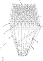
- FIG. 1 illustrating a high temperature thermal energy storage 1 of the invention, in a mixed view of cross section and end view with the end wall taken away.
- the storage comprises a number of easily installable and replaceable concrete thermal energy storage elements 2, the elements have been arranged in one stack of elements.
- the illustrated storage contains 128 elements, illustrated in cross section.
- the elements 2 have heat exchangers 3, embedded in the concrete, the ends and connections between heat exchangers, extending out from the concrete or outside the concrete, can be seen as black dots 3 in the upper and lower elements in a vertically aligned row of elements, or as vertical black lines 3,4 between vertically aligned elements, the vertical black line illustrating piping connecting elements over and under, respectively.
- Said vertical lines are alternatively part of a pipe system 4 for thermal energy input and output, comprising an inlet and an outlet for thermal input to and output from the storage, respectively, and arranged with connections to the heat exchangers for circulating fluid through said heat exchangers for thermal energy input or output.
- the storage comprises a housing 5 into which said elements have been arranged, with a floor 6, also termed a foundation, a fundament or a base, sidewalls 7 and a roof 8.
- the floor includes concrete fill-ins 9, or similar, for supporting and positioning the lowest row of elements.
- the housing comprises thermal insulation 10, in the illustrated embodiment integrated in the housing floor, sidewalls and roof and not illustrated specifically. Alternatively, the insulation can be inside or outside the walls, floor and roof of the housing as distinct layers of insulation.
- the illustrated storage comprises a support system 11, allowing a large number of thermal elements 2 to be stacked whilst still allowing operation at high temperature.
- the illustrated support system 11 comprises a honeycomb support structure 12 and a support steel frame 13.
- the honeycomb support structure consists of honeycomb support layers 14, arranged layer by layer, "valley over hill”.
- the honeycomb layers provide a self-supporting structure, in addition to preferably being supported also by the support frame toward the sidewalls and the floor below. Neighboring columns of elements are vertically staggered, as illustrated, allowing a simplified pipe system.
- the support system must be dimensioned to provide structural strength over the operating conditions and life of the storage, allowing thermal expansion of the elements at a sufficient degree to avoid cracking of the elements.
- the support system as assembled, more precisely the self-supporting structure, containing concrete thermal energy storage elements containing embedded heat exchangers, is in this context termed a cassette.
- a cassette an active heat transfer and storage medium in the form of a phase change material 18, in the volume between the elements and housing, is illustrated.
- Active heat transfer fluids and related features and steps are preferably as explained in patent application NO 20141540 and patent family members, to which application reference is made and the teaching of which application hereby is incorporated by reference.
- FIG. 2 illustrates a cassette 19 preferable for a storage of the invention.
- the cassette comprises a frame 20 and 9 by 6 columns of concrete thermal energy storage elements 2.
- the concrete thermal energy storage elements comprises an outer metal shell 15, closed in one end and open in the other end, and embedded tube heat exchangers 3 with ends 4 extending out from the concrete. Said ends can alternatively be considered part of a pipe system 4, and it may include valves or other means for bypassing or isolating elements.
- the heat exchangers and ends including a header or manifold at a high level and a low level with said elements as horizontally oriented, are welded and formed as one piece covering all elements in a cassette.
- the elongated frame 20 When casting concrete in the cassette, the elongated frame 20 is arranged in vertical position with upwards open elongated metal shells 15 with heat exchangers 3 inside, concrete or grout is filled up until only the ends 4 of the heat exchangers extend up over the steel shells and concrete.
- Said concrete 24 is the white area between said ends 3 and said outer metal shells 15. Then the concrete is cured, typically over several days, the cassette is then flipped down to horizontal orientation, as illustrated, and arranged in intended position and orientation in a storage of the invention.
- the illustrated heat exchangers comprises embedded parts of U-shaped pipe or tubes, extending almost to the other end of the outer shells, which other ends are closed.
- the heat exchangers are built as one small tube inside a larger tube, the larger tube is closed in the embedded end that reaches further into the concrete than an open inner pipe.
- Typical dimensions of concrete thermal energy storage elements are outer diameter OD 200 to 500 mm and length 3 000 to 12 000 mm.
- the heat exchanger is a U-shaped small diameter tube dimensioned to provide turbulent flow of the heat transfer fluid at normal operating conditions. For a small diameter tube heat exchanger, this means that Re > 4000, more preferably Re > 5000, where Re is the Reynold's number. To this end, the tubes must have relatively small internal diameter compared to the flow rate, hence the term small diameter tube.
- Examples on typical small tube outer diameters are 10 mm, 15 mm, 20 mm, 25 mm, 30 mm, 35 mm, 40 mm, 45 mm, 50 mm or up to 60 mm, or any diameter in between, for example 26.7 mm corresponding to Diameter Nominal (DN) 20.
- the concrete thermal energy storage elements, including the heat exchangers, are preferably according to the teaching of patent application PCT/NO2014/050250 , to which reference is made and the teaching of which hereby is incorporated by reference.
- the illustrated frame has dimensions to contain 6 x 9 closely stacked such elements.
- the concrete thermal energy storage elements are larger or smaller in diameter, in the form of one or several elements, with or without outer metal shell, but inside a frame allowing easy production, handling and stacking, without undue cracking or unduly limiting the maximum temperature or the feasible temperature range for operation without undue crack formation.
- Cassettes with 4 x 5, 5 x 7, 7 x 9 or other combinations are feasible.
- an outer metal shell of the concrete thermal energy storage element and a cassette frame are combined as one structure functioning as a form for casting of concrete, armoring for the concrete, heat transfer fluid leakage catcher and the self-supporting modular cassette structure in a thermal energy storage of the invention.
- Said combined structure can be combined with a single structure heat exchanger for one cassette, preferably preassembled and tested, for example as illustrated on Figure 2 , this may represent the most preferable embodiment for a thermal energy storage of the invention with cassettes and/or storage of small to medium size.
- Said combined outer shell/frame cassette can be feasible for cassette/element cross section diameters up to about 10 m 2 and number of embedded U-shaped pipe bends up to about 100 and temperatures up to about 570 °C.
- Small to medium sized cassettes means in this context cassette cross section area up to about 10 m 2 .
- the combined frame/outer metal shell comprises guideposts on top and funnels at the bottom, or similar structure for easy stacking, lifting eyes and coupling parts for attaching adapted insulated modular wall and roof elements.
- concrete thermal energy storage elements with large diameter or cross section area may have several disadvantages in practice. Firstly, the period for curing and drying for high temperature service may become excessively long. Secondly, the risk of cracking and other quality problems increases. Thirdly, the outer shell/self-supporting frame must be excessively solid/strong with increasing size. Fourthly, and probably most important, given a similar configuration of the embedded heat exchanger piping, the temperature distribution in a large element or cassette becomes uniform, where the exergy (energy that is available to be used) is reduced which actually reduces the efficiency compared to the standard concrete thermal energy element design with about 250 mm diameter round elements or similar. This relates to period/frequency of loading/unloading of thermal energy, temperature difference between hot-cold fluid and concrete, which influence dynamic response and specific storage efficiency, such as cost per stored or cycled energy unit.
- FIG. 3 illustrates an embodiment of a high temperature thermal energy storage 1 of the invention.
- the illustrated storage is a large storage, comprising many cassettes 19, in stacks with five cassettes, arranged as a row of stacks on a foundation 6.
- the illustrated storage comprises a separate roof structure 8 and separate wall structures 7, both structures thermally insulated.
- a short gap and a fluid barrier between the pipe structure and thermal insulation 10 allows any heat transfer fluid leaking out to flow downward (if liquid) or upwards (if vapor) without soaking the insulation, thereby reducing the risk of fire in case of thermal oil or other flammable heat transfer fluid.
- Each cassette comprises two manifolds, one at a high position and one at a low positon with elongated frame and concrete thermal energy storage elements inside orientated horizontally, as illustrated.
- the stacks are typically coupled in parallel, and arranged side by side as blocks stacks, each block with an assembled group of stacks comprises a main manifold 21 at a high elevation and a main manifold 22 at a low elevation.
- Each block can be thermally insulated from other blocks or groups of blocks, enabling isolation of individual blocks, cooling down, drainage of heat transfer fluid, inspection and maintenance, without affecting the remaining blocks of the storage. Said functionality significantly increases the availability of the storage system.
- FIG 4 illustrates some details of the high temperature thermal energy storage of the invention illustrated on Figure 3 , more specifically how cassettes 19 and pipe systems are arranged.
- Each cassette comprises two manifolds 4, one at high elevation and one at low elevation.
- the manifolds are coupled in series in each stack, by u-bends 23.
- the self-supporting structure in a storage of the invention facilitate building and reduced cost compared to prior art storages, irrespective of the self-supporting structure comprises a honeycomb support structure or similar assembled while building it, for example as illustrated in Fig. 1 , or a modular structure comprising several cassettes, for example as illustrated in Fig. 3 .
- the cassettes and parts thereof are preferably prefabricated and tested, and then transported and installed easily, as they are preferably not made too large and heavy.
- the cassette frames preferably provide a truss-type structure per se and as stacked.
- the cassette frame provides structural strength for stacking and also a strong structure for handling and transport, irrespective of the concrete thermal energy storage elements comprises an outer metal casing or similar, or not.
- the concrete thermal energy storage elements preferably comprises an outer metal shell or casing, since this facilitates production, handling, safety and efficiency as discussed.
- an outer metal shell or casing also improves durability, increases the maximum operating temperature and the operating temperature range, particularly if the outer metal shell or casing is round in cross section shape.
- the arrangement of having embedded heat exchangers with inlet and outlet in the concrete thermal energy storage elements on only one side of cassettes, stacks, rows or blocks of cassettes have not only practical advantages, but also provides better stress/strain distribution, since only a radial stress/strain gradient is significant, which improves efficiency, response and durability over other designs, such as those provided by DLR.
- the elements can be self-supporting, particularly if they comprise an outer metal shell being a combined casting form and reinforcement.
- Elements with hexagonal, quadratic or rectangular cross section shape are most feasible for stacking of self-supporting cassettes and elements as combined, quadratic elements can be rotated 45 around the longitudinal axis to provide a position adjusting wedge shape upwards, facilitating building the storage. More comprehensive and solid support systems are required for larger storages and for higher operating temperatures.
- Parts that are to be coupled preferably comprises coupling parts such as guide posts/cones and guide pins/posts, or similar male-female coupling parts.
- high temperature in the context of the invention do not mean that the storage must be used for high temperature, but preferably is used for high temperature operation, which in this context is from 100 °C up to 570 °C for storages with exposed element steel shells and pipe systems, and up to 1000-1200 °C or even 1500 °C for storages with elements without steel shells or exposed steel pipe system parts, the otherwise exposed metal parts preferably being insulated or made of high temperature resistant alloys or material.
- the storage of the invention can operate at very high dynamic temperature range, including large temperature differences between fluid and elements, compared to prior art storages.
- the high temperature thermal energy storage of the invention is defined by the following claims.
Landscapes
- Engineering & Computer Science (AREA)
- Physics & Mathematics (AREA)
- Thermal Sciences (AREA)
- Mechanical Engineering (AREA)
- General Engineering & Computer Science (AREA)
- Building Environments (AREA)
- Filling Or Discharging Of Gas Storage Vessels (AREA)
- Heat-Exchange Devices With Radiators And Conduit Assemblies (AREA)
- Central Heating Systems (AREA)
- Processing And Handling Of Plastics And Other Materials For Molding In General (AREA)
- Secondary Cells (AREA)
- Control Of Vending Devices And Auxiliary Devices For Vending Devices (AREA)
Claims (16)
- Procédé de construction d'une unité de stockage d'énergie thermique à haute température, dans lequel le procédé comprend les étapes consistant à :construire une fondation isolée thermiquement pour l'unité de stockage,construire au moins une cassette autoportée contenant un certain nombre d'éléments de stockage d'énergie thermique en béton, laquelle cassette est une ossature ou structure autoportante par rapport au transport et à l'installation,en construisant ladite ossature ou structure,en construisant un certain nombre d'éléments de stockage d'énergie thermique en béton individuels, certains ou tous lesdits éléments comprenant des échangeurs de chaleur noyés dans ledit béton, eten agençant lesdits éléments dans ladite ossature ou structure, agencer et/ou construire la au moins une cassette sur ladite fondation,construire et connecter de manière opérationnelle un système de canalisation, le système de canalisation comprenant une entrée vers et une sortie depuis l'unité de stockage, respectivement, et des connexions aux échangeurs de chaleur pour faire circuler un fluide à travers lesdits échangeurs de chaleur pour l'entrée ou la sortie d'énergie thermique à partir desdits éléments de stockage d'énergie thermique, etagencer une isolation thermique autour et au-dessus des cassettes autoportantes contenant des éléments de stockage d'énergie thermique en béton.
- Procédé selon la revendication 1, comprenant une ou plusieurs des étapes consistant à :empiler un certain nombre de cassettes verticalement sur la fondation, en construisant une ou plusieurs piles de cassettes agencées en une ou plusieurs rangées de piles ;agencer la pile ou les piles de cassettes de manière à ce que les éléments de stockage d'énergie thermique en béton soient orientés horizontalement ;agencer des cassettes avec des éléments de stockage d'énergie thermique en béton se tenant verticalement sur la fondation, ce qui est particulièrement réalisable avec du gaz comme fluide caloporteur, et comprenant de préférence l'étape de construction desdites cassettes avec lesdits éléments se tenant verticalement sur la fondation,agencer le système de canalisation sur un premier côté de la cassette ou de la pile de cassettes ;connecter les cassettes verticales en série via des tuyaux qui se connectent aux échangeurs de chaleur dans les cassettes ;agencer le système de canalisation de sorte que plusieurs piles de cassettes soient couplées en parallèle ;agencer le système de canalisation et les cassettes ou piles de cassettes en blocs, de sorte que chaque bloc puisse être isolé du reste de l'unité de stockage en actionnant des vannes du système de canalisation ;empiler et disposer de cassettes conditionnées de manière à minimiser le rapport entre l'aire de surface extérieure et le volume, pour obtenir un volume conditionné serré de l'unité de stockage avec un faible encombrement,agencer les cassettes de manière à ce que les éléments de stockage d'énergie thermique en béton soient orientés horizontalement et à ce que le système de canalisation soit disposé sur un premier côté des cassettes dans une rangée de cassettes, faisant face à un premier côté de l'unité stockage,combiner une enveloppe métallique extérieure de l'élément de stockage d'énergie thermique en béton et l'ossature de cassette en une seule structure fonctionnant comme un moule pour couler du béton, une armature pour le béton, un capteur de fuite de fluide caloporteur et la structure de cassette modulaire autoportante,agencer ou construire un échangeur de chaleur pour une cassette ou un élément de stockage d'énergie thermique en béton sous la forme d'une structure unique.
- Procédé selon la revendication 1 ou 2, dans lequel l'étape de construction d'au moins une cassette autoportée comprend les étapes consistant à :construire une ossature,agencer des enveloppes métalliques extérieures d'éléments de stockage d'énergie thermique dans l'ossature, les enveloppes métalliques extérieures des éléments de stockage d'énergie thermique étant un moule de coulée combiné, de renforcement et de confinement de fluide pour une entrée ou une sortie d'énergie thermique en cas de fuite de fluide ;agencer des échangeurs de chaleur et des dispositifs de chauffage électriques facultatifs dans lesdites enveloppes métalliques ;avec lesdites enveloppes métalliques extérieures orientées dans une position verticale debout et avec une extrémité supérieure ouverte, verser du coulis ou du mélange de béton jusqu'à un niveau prescrit, niveau auquel les extrémités ou les connexions desdits échangeurs de chaleur s'étendent sur le dessus des éléments en position debout verticale ;durcir le coulis ou le béton, etmanipuler et transporter la cassette, en plaçant la cassette dans sa position et son orientation prévues dans l'unité de stockage,dans lequel l'ossature est utilisée non seulement comme un accessoire pour couler et durcir les éléments de stockage d'énergie thermique en béton, et une structure pour faciliter la manutention et le transport desdits éléments, mais également comme structure autoportante pour l'unité de stockage elle-même et les piles de cassettes dans l'unité stockage.
- Procédé selon l'une quelconque des revendications 1 à 3, comprenant une ou plusieurs des étapes consistant à :construire des éléments de stockage d'énergie thermique en béton allongés et des ossatures de cassette allongées, et orienter les éléments et la cassette horizontalement lors de l'agencement des cassettes avec des éléments dans l'unité de stockage,agencer le système de canalisation pour l'entrée et la sortie d'énergie thermique de sorte que l'entrée et la sortie vers l'unité de stockage puissent être modifiées de manière réversible et de sorte qu'au moins une entrée ou une sortie soit agencée à une hauteur élevée de l'unité de stockage et qu'au moins une entrée ou une sortie soit agencée à une faible hauteur de l'unité stockage, et agencer les connexions et/ou vannes par rapport aux échangeurs de chaleur des éléments d'énergie thermique de sorte que du fluide puisse circuler à travers lesdits échangeurs de chaleur progressivement ou par étapes verticalement vers le haut ou vers le bas ou sur le côté horizontalement ;agencer les cassettes en piles ou blocs avec plusieurs piles de cassettes, avec le système de canalisation de sorte que le système de canalisation ne soit agencé que sur un côté de ladite pile ou dudit bloc d'éléments, de préférence faisant face à une paroi de l'unité de stockage,agencer des cassettes ou une structure autoportante(s) avec des pièces de couplage pour des éléments de toit et/ou de paroi, et des éléments de toit et/ou de paroi isolés thermiquement comprenant des pièces de couplage s'appariant aux pièces de couplage de cassette ou de structure, agencer et coupler lesdits éléments sous la forme de toit et murs isolés thermiquement, respectivement.
- Procédé selon la revendication 1, comprenant une ou plusieurs des étapes consistant à :agencer les éléments de stockage d'énergie thermique en béton en piles dans une ossature comprenant deux parois latérales opposées et un plancher mais pas de toit, les éléments reposant sur des éléments en-dessous tels qu'ils sont contenus orientés horizontalement à l'intérieur des parois latérales, en fournissant ainsi des cassettes qui sont ouvertes vers le haut mais qui peuvent facilement être empilées les unes sur les autres,agencer les éléments en piles, avec des inserts, des supports, des cales ou des objets similaires entre les éléments, dans des positions régulières ou irrégulières sur la longueur des éléments, en prévoyant une distance entre les éléments, lesdits inserts, supports, cales ou objets similaires entre les éléments comprenant des pièces de couplage constituant une structure de cassette autoportante empilée et couplée,agencer les éléments en piles, avec des pièces de système de support entre les éléments, les pièces de système de support comprenant des pièces de couplage et sont agencées dans des positions régulières ou irrégulières sur la longueur des éléments, en fournissant une distance entre les éléments, les pièces de système de support étant couplées fournissent une structure autoportante comprenant des ouvertures pour des éléments, les ouvertures ayant une forme hexagonale, une forme carrée, une forme rectangulaire, une forme ronde, une forme elliptique, une forme triangulaire ou une autre forme dans laquelle les éléments s'ajustent,agencer les éléments en piles, avec des couches de système de support entre les éléments, les couches de système de support comprenant des pièces de couplage dans des positions régulières ou irrégulières sur la longueur des éléments, en prévoyant une distance entre les éléments, les couches de système de support étant couplées fournissent une structure autoportante comprenant les couches du système de support assemblées ou couplées et empilées, fournissant un système de support avec des ouvertures pour des éléments, les ouvertures ayant une forme hexagonale, une forme carrée, une forme rectangulaire, une forme ronde, une forme elliptique, une forme triangulaire ou une autre forme dans laquelle les éléments s'ajustent,verser un milieu de transfert et de stockage de chaleur actif sous la forme d'un matériau à changement de phase, dans le volume entre les éléments et un boîtier de stockage, ouverser un milieu de transfert et de stockage de chaleur actif sous la forme d'un liquide stagnant, dans le volume entre les éléments et un boîtier de stockage, ouverser un milieu de transfert et de stockage de chaleur actif sous la forme d'un fluide dynamique, dans le volume entre les éléments et un boîtier de stockage, de sorte que le fluide dynamique puisse s'écouler entre les éléments et les cassettes d'une entrée vers le boîtier jusqu'à une sortie depuis le boîtier.
- Unité de stockage d'énergie thermique à haute température comprenant :une fondation isolée thermiquement,au moins une cassette autoportée agencée sur ladite fondation contenant un certain nombre d'éléments de stockage d'énergie thermique en béton, certains ou la totalité desdits éléments comprenant des échangeurs de chaleur noyés dans le béton desdits éléments de stockage d'énergie thermique en béton,un système de canalisation, le système de canalisation comprenant une entrée et une sortie pour une entrée thermique vers et une sortie depuis l'unité de stockage, respectivement, et des connexions auxdits échangeurs de chaleur pour faire circuler du fluide à travers lesdits échangeurs de chaleur pour une entrée ou une sortie d'énergie thermique vers et depuis les éléments de stockage d'énergie thermique, etune isolation thermique autour et au-dessus de la au moins une cassette autoportée avec des éléments de stockage d'énergie thermique en béton ; caractérisée en ce que ladite au moins une cassette est une ossature ou une structure autoportante par rapport au transport et à l'installation.
- Unité de stockage d'énergie thermique à haute température selon la revendication 6, comprenant une ou plusieurs des caractéristiques suivantes :une ou plusieurs piles verticales de cassettes ;des piles de cassettes agencées de manière à ce que les éléments de stockage d'énergie thermique en béton soient orientés horizontalement ;des cassettes agencées avec des éléments de stockage thermique en béton en position debout verticalement sur la fondation, ce qui est particulièrement réalisable avec du gaz en tant que fluide caloporteur,un système de canalisation sur un côté de la cassette ou de la pile de cassettes ;un système de tuyaux agencé de telle sorte que plusieurs piles de cassettes sont couplées en parallèle ;un système de canalisation et des cassettes ou des piles de cassettes agencées en blocs, de sorte que chaque bloc puisse être isolé ou contourné, un après l'autre ou par étapes, par rapport au reste de l'unité de stockage en actionnant de vannes du système de canalisation,un système de canalisation agencé de telle sorte que des éléments thermiques individuels et des cassettes individuelles peuvent être isolés ou contournés, l'un après l'autre ou par étapes, par rapport reste de l'unité de stockage, en actionnant des vannes du système de canalisation,une pile ou des piles de cassettes empilées et agencées de manière serrée de telle sorte qu'un rapport entre l'aire de surface extérieure d'unité de stockage et le volume est minimisé, obtenant un faible encombrement et une faible perte de chaleur de l'unité de stockage,les cassettes agencées de sorte que les éléments de stockage d'énergie thermique en béton soient orientés horizontalement et avec le système de canalisation disposé agencé sur un premier côté dans une rangée de cassettes empilées, faisant face à un côté de l'unité de stockage,une enveloppe métallique extérieure combinée de l'élément de stockage d'énergie thermique en béton et de l'ossature de cassette sous la forme d'une structure unique fonctionnant comme un moule pour couler du béton, une armature pour le béton, un capteur de fuite de fluide caloporteur et la structure de cassette modulaire,un échangeur de chaleur pour une cassette ou un élément de stockage d'énergie thermique en béton sous la forme d'une structure unique.
- Stockage d'énergie thermique à haute température selon la revendication 6 ou 7, comprenant des éléments de stockage d'énergie thermique comprenant
une enveloppe métallique extérieure,
un échangeur de chaleur tubulaire intégré,
du béton ou coulis durci à l'intérieur de l'enveloppe, avec des extrémités ou des connexions d'échangeurs de chaleur s'étendant à l'extérieur du béton,
dans lequel l'enveloppe extérieure est un moule de coulée combiné, de renforcement et de confinement de fluide pour une entrée ou une sortie d'énergie thermique en cas de fuite d'échangeur de chaleur intégré. - Unité de stockage d'énergie thermique à haute température selon la revendication 6 à 8, comprenant un système de canalisation pour l'entrée et la sortie d'énergie thermique agencé de manière à ce que l'entrée et la sortie de l'unité de stockage puissent être modifiées de manière réversible et de manière à ce qu'au moins une entrée ou une sortie soit agencée à une hauteur élevée de l'unité de stockage et à ce qu'au moins une entrée ou une sortie soit agencée à une faible hauteur de l'unité de stockage, et des connexions ou des vannes vers un ou plusieurs groupes d'échangeurs de chaleur des éléments d'énergie thermique agencées de manière à ce que du fluide puisse être mis en circulation à travers ledit échangeurs de chaleur progressivement ou par étapes vers le haut ou vers le bas.
- Unité de stockage d'énergie thermique à haute température selon la revendication 6 à 9, comprenant un empilement de cassettes autoportées, les cassettes comprenant une ossature ouverte à au moins une extrémité, contenant des éléments de stockage d'énergie thermique en béton conditionnés de manière serrée avec une enveloppe métallique extérieure et des échangeurs de chaleur tubulaires noyés dans le béton, lesdits éléments étant agencés dans une orientation horizontale en des piles de cassettes verticales, dans lequel l'ossature n'est pas seulement un accessoire pour la coulée et le durcissement desdits éléments, et une structure pour faciliter la manutention et le transport, mais aussi comme une structure pour l'unité de stockage elle-même et les piles de cassettes dans l'unité de stockage.
- Unité de stockage d'énergie thermique à haute température selon les revendications 6 à 10, comprenant des ossatures de cassette autoportante ou une structure avec des pièces de couplage pour des éléments de toit et/ou de paroi, et des éléments de toit et/ou de paroi isolés thermiquement comprenant des pièces de couplage appariant l'ossature de cassette ou les pièces de couplage de structure, agencées et couplées respectivement sous forme de toit et de parois isolés thermiquement.
- Unité de stockage d'énergie thermique à haute température selon les revendications 6 à 11, comprenant une ou plusieurs des caractéristiques suivantes :au moins deux ossatures de support, constitués de parties d'ossature de support assemblées alignées verticalement, décalées ou inversées en miroir d'une couche à l'autre, les éléments de stockage d'énergie thermique ayant été agencés dans et étant supportés par lesdites ossatures,des cassettes comprenant une ossature comprenant deux parois latérales opposées et un plancher mais pas de toit, avec les éléments de stockage d'énergie thermique en béton empilés à l'intérieur, les éléments reposant sur les éléments en dessous tels qu'ils sont contenus orientés horizontalement dans les parois latérales, en fournissant ainsi des cassettes qui sont ouvertes vers le haut mais peuvent facilement être empilées les unes sur les autres,des piles, avec des inserts, supports, cales ou objets similaires entre les éléments, à des positions régulières ou irrégulières sur la longueur des éléments, fournissant une distance entre les éléments, lesdits inserts, supports, cales ou objets similaires entre les éléments comprenant des pièces de couplage assurant une structure de cassette autoportante lorsqu'empilée et couplée,des pièces de système de support entre les éléments, les pièces de système de support comprenant des pièces de couplage et sont agencées dans des positions régulières ou irrégulières sur la longueur des éléments, en fournissant une distance entre les éléments, les pièces de système de support couplées fournissant une structure autoportante comprenant des ouvertures pour des éléments, les ouvertures ayant une forme hexagonale, une forme carrée, une forme rectangulaire, une forme ronde, une forme elliptique, une forme triangulaire ou une autre forme dans laquelle les éléments s'ajustent,de couches de système de support entre les éléments, les couches de système de support comprenant des pièces de couplage dans des positions régulières ou irrégulières sur la longueur des éléments, en fournissant une distance entre les éléments, les couches de système de support couplées fournissant une structure autoportante comprenant les couches de système de support assemblées ou couplées et empilées, fournissant un système de support avec des ouvertures pour des éléments, les ouvertures ayant une forme hexagonale, une forme carrée, une forme rectangulaire, une forme ronde, une forme elliptique, une forme triangulaire ou une autre forme dans laquelle les éléments s'insèrent,un milieu de transfert et de stockage de chaleur actif sous la forme d'un matériau à changement de phase, dans le volume entre les éléments et un boîtier, ouun milieu de transfert et de stockage de chaleur actif sous la forme d'un liquide stagnant, dans le volume entre les éléments et un boîtier, ouun milieu de transfert et de stockage de chaleur actif sous la forme d'un fluide dynamique, dans le volume entre les éléments et un boîtier, le fluide dynamique pouvant s'écouler d'une entrée vers le boîtier à une sortie depuis le boîtier.
- Procédé de fonctionnement d'une unité de stockage d'énergie thermique à haute température selon l'une quelconque des revendications 6 à 12, caractérisé en ce que le procédé comprend les étapes consistant à :faire circuler du fluide caloporteur à une température supérieure à l'unité de stockage, pour une entrée d'énergie thermique vers l'unité de stockage, par étapes ou progressivement d'une hauteur plus élevée à une hauteur moins élevée dans l'unité de stockage, en faisant fonctionner le système de canalisation en conséquence, etfaire circuler du fluide caloporteur à une température inférieure à l'unité de stockage, pour une sortie d'énergie thermique depuis l'unité de stockage, par étapes ou progressivement d'une hauteur moins élevée à une hauteur plus élevée dans l'unité de stockage, en faisant fonctionner le système de canalisation en conséquence.
- Procédé selon la revendication 13, dans lequel l'unité de stockage contient un matériau à changement de phase dans le volume entre les éléments de stockage d'énergie thermique en béton et le boîtier, et de l'eau est mise en circulation à travers des échangeurs de chaleur noyés dans lesdits éléments lorsque de l'énergie thermique est extraite de l'unité de stockage, de telle sorte que l'unité de stockage est actionnée dans des conditions telles que le matériau à changement de phase se solidifie pendant que l'eau s'évapore, en utilisant ainsi la chaleur de solidification du matériau à changement de phase comme chaleur d'évaporation pour l'eau.
- Procédé selon la revendication 13, pour faire fonctionner l'unité de stockage avec une huile thermique ou un autre liquide à phase unique en tant que fluide caloporteur, de telle sorte que
la circulation pour une entrée d'énergie thermique vers l'unité de stockage intervient via une entrée à une hauteur la plus élevée de l'unité stockage, en dirigeant le fluide plus chaud vers les éléments les plus élevés ou les éléments à une hauteur avec une température inférieure à celle du fluide plus chaud ; et
la circulation pour une sortie d'énergie thermique de l'unité de stockage intervient via une entrée à une hauteur la moins élevée de l'unité de stockage, en dirigeant le fluide le plus froid vers les éléments les moins élevés ou les éléments à une hauteur avec une température supérieure à celle du fluide plus froid,
dans lequel ladite circulation intervient par pompage avec une pompe lorsqu'une huile thermique ou un autre liquide à phase unique est le fluide caloporteur mis en circulation. - Procédé de fonctionnement d'une unité de stockage d'énergie thermique à haute température selon l'une quelconque des revendications 6 à 12, pour faire fonctionner l'unité de stockage avec de l'eau/vapeur, du GPL ou un autre mélange liquide-gaz à deux phases en tant que fluide caloporteur, avec des éléments de stockage d'énergie thermique en béton orientés horizontalement et avec un séparateur liquide/gaz connecté à hauteur élevée et connecté avec un ou plusieurs tuyaux extérieurement au (x) tuyau (s) d'entrée à une hauteur basse, permettant une circulation naturelle par gravité sans l'utilisation d'une pompe, l'unité de stockage agissant comme un condenseur lorsque l'unité de stockage est en charge et comme une chaudière lorsque l'unité de stockage décharge de l'énergie thermique, caractérisée par les étapes consistant à :ajouter de la vapeur ou un autre gaz via une entrée à une hauteur la moins élevée de l'unité de stockage stockage, le gaz étant ajouté au liquide soit via un tuyau ou généré par des résistances électriques à l'intérieur du tuyau, lors d'une charge d'énergie thermique,ajouter de l'eau ou un autre liquide via une entrée à la hauteur la plus élevée de l'unité de stockage, de sorte que de l'eau ou un autre liquide est ajouté(e) à un séparateur gaz/liquide tel qu'un tambour à vapeur, en variante l'eau ou un autre liquide est ajouté(e) à la hauteur la moins élevée de l'unité de stockage, et de la vapeur ou un autre gaz est extrait(e) du séparateur liquide/gaz au niveau du haut,dans lequel du liquide s'écoule vers le bas dans le ou les tuyaux externes et le mélange liquide-gaz s'écoule vers le haut dans l'unité de stockage, à la fois en mode de charge et de décharge.
Priority Applications (3)
| Application Number | Priority Date | Filing Date | Title |
|---|---|---|---|
| SI201531579T SI3247963T1 (sl) | 2014-12-19 | 2015-12-18 | Visokotemperaturni hranilnik toplotne energije, postopek za izdelavo in postopek za delovanje hranilnika |
| HRP20210672TT HRP20210672T1 (hr) | 2014-12-19 | 2015-12-18 | Visokotemperaturni spremnik toplinske energije, postupak izgradnje i postupak upravljanja takvim spremnikom |
| PL15870420T PL3247963T3 (pl) | 2014-12-19 | 2015-12-18 | Magazyn wysokotemperaturowej energii cieplnej, sposób budowania oraz sposób obsługiwania wspomnianego magazynu |
Applications Claiming Priority (2)
| Application Number | Priority Date | Filing Date | Title |
|---|---|---|---|
| NO20141546A NO340371B1 (no) | 2014-12-19 | 2014-12-19 | Høytemperatur termisk energilager, fremgangsmåte for bygging og fremgangsmåte for drift av dette lageret |
| PCT/NO2015/050252 WO2016099289A1 (fr) | 2014-12-19 | 2015-12-18 | Système d'accumulation d'énergie thermique à haute température, procédé de construction et procédé d'exploitation dudit système d'accumulation |
Publications (3)
| Publication Number | Publication Date |
|---|---|
| EP3247963A1 EP3247963A1 (fr) | 2017-11-29 |
| EP3247963A4 EP3247963A4 (fr) | 2018-10-03 |
| EP3247963B1 true EP3247963B1 (fr) | 2021-01-27 |
Family
ID=56127026
Family Applications (1)
| Application Number | Title | Priority Date | Filing Date |
|---|---|---|---|
| EP15870420.5A Active EP3247963B1 (fr) | 2014-12-19 | 2015-12-18 | Système d'accumulation d'énergie thermique à haute température, procédé de construction et procédé d'exploitation dudit système d'accumulation |
Country Status (15)
| Country | Link |
|---|---|
| US (1) | US10591224B2 (fr) |
| EP (1) | EP3247963B1 (fr) |
| CN (1) | CN107250707B (fr) |
| AU (1) | AU2015363808B2 (fr) |
| DK (1) | DK3247963T3 (fr) |
| ES (1) | ES2864761T3 (fr) |
| HR (1) | HRP20210672T1 (fr) |
| HU (1) | HUE053934T2 (fr) |
| LT (1) | LT3247963T (fr) |
| MA (1) | MA41361B1 (fr) |
| NO (1) | NO340371B1 (fr) |
| PL (1) | PL3247963T3 (fr) |
| PT (1) | PT3247963T (fr) |
| SI (1) | SI3247963T1 (fr) |
| WO (1) | WO2016099289A1 (fr) |
Families Citing this family (35)
| Publication number | Priority date | Publication date | Assignee | Title |
|---|---|---|---|---|
| US10012451B2 (en) * | 2012-08-20 | 2018-07-03 | Phase Change Energy Solutions, Inc. | Thermal energy storage systems including a shipping container, a heat exchange apparatus, and a phase change material |
| NO339948B1 (no) | 2013-12-20 | 2017-02-20 | Energynest As | Element for termisk energilager |
| NO339952B1 (no) | 2014-12-19 | 2017-02-20 | Energynest As | Termisk energilager og varmeveklser |
| US11692778B2 (en) | 2017-06-21 | 2023-07-04 | Westinghouse Electric Company Llc | Energy storage device |
| EP3642548B1 (fr) * | 2017-06-21 | 2023-07-05 | Westinghouse Electric Company Llc | Dispositif de stockage d'énergie |
| EP3688377B1 (fr) | 2017-09-25 | 2024-05-08 | Nostromo Ltd. | Ensemble de stockage d'énergie thermique |
| US12331956B2 (en) | 2017-09-25 | 2025-06-17 | Nostromo Ltd. | Fluid flow in thermal storage containers |
| NO344182B1 (en) | 2017-12-05 | 2019-09-30 | Energynest As | Modular thermal energy storage system, improved method of operation of such systems and use of the thermal energy storage system |
| DE102018109846B4 (de) * | 2018-04-24 | 2020-11-19 | Heinrich Graucob | Verfahren zur Einspeicherung elektrischer Energie |
| US10505511B1 (en) | 2018-06-20 | 2019-12-10 | Psemi Corporation | High resolution attenuator or phase shifter with weighted bits |
| JP7477180B2 (ja) * | 2018-09-25 | 2024-05-01 | ノストローモ リミテッド | 蓄熱容器内の流体の流れ |
| US10876765B2 (en) | 2018-11-28 | 2020-12-29 | Element 16 Technologies, Inc. | Systems and methods of thermal energy storage |
| DE102019131345A1 (de) * | 2018-12-07 | 2020-06-10 | IVOC-X GmbH | Verfahren zum Ausführen einer zyklischen Energiespeicherung und Vorrichtung hierfür |
| US12291982B2 (en) | 2020-11-30 | 2025-05-06 | Rondo Energy, Inc. | Thermal energy storage systems for use in material processing |
| JP6642775B1 (ja) | 2019-04-03 | 2020-02-12 | 三菱電機株式会社 | 熱交換装置および製造方法 |
| ES2728439A1 (es) * | 2019-05-13 | 2019-10-24 | Julio Martinez Naya S A | Equipo de acumulacion e intercambio de calor por resistencias electricas en triangulacion para calentar un fluido |
| WO2020251373A1 (fr) | 2019-06-12 | 2020-12-17 | Energynest As | Batterie à énergie thermique |
| CA3162982A1 (fr) * | 2020-01-13 | 2021-07-22 | Other Lab Llc | Systeme et procede de stockage thermique |
| CN112066770B (zh) * | 2020-09-21 | 2022-03-25 | 中国建筑科学研究院有限公司 | 一种建筑用储能源的系统 |
| EP4233102A4 (fr) | 2020-10-23 | 2024-09-11 | Massachusetts Institute Of Technology | Système de briques réfractaires électriquement conductrices |
| DE102020127987A1 (de) * | 2020-10-23 | 2022-04-28 | Kraftblock Gmbh | Fraktalspeicher |
| US12018596B2 (en) | 2020-11-30 | 2024-06-25 | Rondo Energy, Inc. | Thermal energy storage system coupled with thermal power cycle systems |
| US11913362B2 (en) | 2020-11-30 | 2024-02-27 | Rondo Energy, Inc. | Thermal energy storage system coupled with steam cracking system |
| AU2021385430A1 (en) * | 2020-11-30 | 2023-07-06 | Rondo Energy, Inc. | Energy storage system and applications |
| US11913361B2 (en) | 2020-11-30 | 2024-02-27 | Rondo Energy, Inc. | Energy storage system and alumina calcination applications |
| US12359591B1 (en) * | 2020-11-30 | 2025-07-15 | Rondo Energy, Inc. | Thermal energy storage systems for repowering existing power plants for improving efficiency and safety |
| US12146424B2 (en) | 2020-11-30 | 2024-11-19 | Rondo Energy, Inc. | Thermal energy storage system coupled with a solid oxide electrolysis system |
| CN115419563B (zh) * | 2022-08-26 | 2025-03-25 | 中国石油大学(华东) | 一种光热发电的热能存储设备 |
| TR2025019634U5 (tr) | 2023-04-14 | 2025-12-22 | Rondo Energy Inc | Isil enerji̇ depolama bloklari ve i̇li̇şki̇li̇ destek yapilari |
| EP4484848A1 (fr) * | 2023-06-27 | 2025-01-01 | Lumenion GmbH | Accumulateur de chaleur avec cartouches d'accumulation de chaleur |
| US12618343B2 (en) | 2023-10-13 | 2026-05-05 | Rondo Energy, Inc. | Thermal energy storage system with a heat pump for improved efficiency |
| WO2025226989A2 (fr) | 2024-04-24 | 2025-10-30 | Rondo Energy, Inc. | Système de stockage d'énergie thermique pour génération d'énergie de cycle simple et combinée |
| US12595973B2 (en) | 2024-05-24 | 2026-04-07 | Rondo Energy, Inc. | Thermal energy storage system with high efficiency heater control |
| US12566034B1 (en) | 2024-07-02 | 2026-03-03 | Rondo Energy, Inc. | Thermal energy storage system coupled to a heat exchanger with thermal protection |
| US12607170B2 (en) | 2024-07-12 | 2026-04-21 | Rondo Energy, Inc. | Thermal energy storage system for use with a low temperature heat source and a thermal power cycle system |
Family Cites Families (66)
| Publication number | Priority date | Publication date | Assignee | Title |
|---|---|---|---|---|
| US3381113A (en) | 1964-09-29 | 1968-04-30 | Albright & Wilson Mfg Ltd | Heat storage apparatus |
| US3624356A (en) | 1970-05-04 | 1971-11-30 | Charles Dewey Havill | Heat storage apparatus |
| US4010731A (en) | 1975-10-23 | 1977-03-08 | Halm Instrument Co., Inc. | Heat storage tank |
| US4085333A (en) * | 1976-02-17 | 1978-04-18 | Grise Frederick Gerard J | Conservation of electrical energy |
| DE2700822C3 (de) | 1977-01-11 | 1979-06-21 | Uwe 2251 Schwabstedt Hansen | Verfahren zum Speichern von Wärmeenergie in einem Wärmespeicher und zur Entnahme der gespeicherten Wärmeenergie und Vorrichtung zur Durchführung des Verfahrens |
| US4203489A (en) | 1977-05-31 | 1980-05-20 | Swiadek Stanley F | Thermal energy storage system |
| US4194496A (en) | 1978-03-30 | 1980-03-25 | Carlson Norman G | Solar heat storage systems |
| US4205656A (en) | 1978-06-06 | 1980-06-03 | Scarlata Robert W | Thermal storage reservoirs |
| US4405010A (en) | 1978-06-28 | 1983-09-20 | Sanders Associates, Inc. | Sensible heat storage unit |
| SE416672B (sv) | 1979-04-18 | 1981-01-26 | Grevare Carl John | Anordning vid vermeanleggningar |
| US4397152A (en) | 1980-09-26 | 1983-08-09 | Smith Derrick A | Solar furnace |
| US4323113A (en) | 1980-10-31 | 1982-04-06 | Troyer Leroy S | Underground air tempering system |
| US4442826A (en) | 1980-11-04 | 1984-04-17 | Pleasants Frank M | Prefabricated panel for building construction and method of manufacturing |
| US4412426A (en) | 1980-12-22 | 1983-11-01 | Yuan Shao W | Wiser cooling system |
| US4395620A (en) | 1981-02-23 | 1983-07-26 | Clyde Robert A | Electric storage heating apparatus |
| US4452229A (en) | 1981-11-13 | 1984-06-05 | Kim Powers | Thermal heat storage and cooling system |
| DE3210370C2 (de) | 1982-02-11 | 1984-04-12 | Walter Dr. 5902 Unglinghausen Helmbold | Langzeit-Wärmespeicher |
| JPS58156151A (ja) | 1982-03-10 | 1983-09-17 | Toshiba Corp | 蓄熱槽 |
| US4524756A (en) * | 1983-07-25 | 1985-06-25 | Chicago Bridge & Iron Company | Thermal energy storage tank using modular heat batteries |
| US5694515A (en) | 1995-01-09 | 1997-12-02 | The University Of Florida | Contact resistance-regulated storage heater for fluids |
| US5816314A (en) | 1995-09-19 | 1998-10-06 | Wiggs; B. Ryland | Geothermal heat exchange unit |
| US5623986A (en) | 1995-09-19 | 1997-04-29 | Wiggs; B. Ryland | Advanced in-ground/in-water heat exchange unit |
| US5833394A (en) | 1996-06-12 | 1998-11-10 | Michael W. Wilson | Composite concrete metal encased stiffeners for metal plate arch-type structures |
| EP0941759A1 (fr) | 1998-03-12 | 1999-09-15 | Nederlandse Organisatie Voor Toegepast-Natuurwetenschappelijk Onderzoek Tno | Echangeur et son procédé de fabrication |
| JP2000161882A (ja) | 1998-11-26 | 2000-06-16 | Hitachi Ltd | 蓄熱・蓄冷槽 |
| JP2000241091A (ja) | 1999-02-23 | 2000-09-08 | Agency Of Ind Science & Technol | 蓄熱装置 |
| CH694868A5 (de) | 2001-03-15 | 2005-08-15 | Fredy Fallegger | Heiz-/Kuehlsystem sowie Verfahren zu seinem Betrieb. |
| US6789608B1 (en) | 2002-04-22 | 2004-09-14 | B. Ryland Wiggs | Thermally exposed, centrally insulated geothermal heat exchange unit |
| US7173179B2 (en) | 2002-07-16 | 2007-02-06 | The Board Of Trustees Of The University Of Arkansas | Solar co-generator |
| JP2004309124A (ja) | 2003-03-25 | 2004-11-04 | Mitsui Eng & Shipbuild Co Ltd | 地中熱交換器 |
| DE10350879A1 (de) | 2003-06-12 | 2005-01-05 | Heiko Hesse | Gebäudewand |
| NO328739B1 (no) | 2004-10-25 | 2010-05-03 | Concryo As | Tank for lagring av LNG eller andre kryogene fluider |
| WO2006072178A1 (fr) * | 2005-01-06 | 2006-07-13 | New World Generation Inc. | Support de stockage thermique |
| DE102005001347A1 (de) | 2005-01-11 | 2006-07-20 | GEOTEX Ingenieurgesellschaft für Straßen- und Tiefbau mbH | Mehrkammerwärmespeicher zur Speicherung von Wärmeenergie und für die Erzeugung elektrischer Energie |
| CA2679918A1 (fr) | 2007-03-06 | 2008-09-12 | A & S Umwelttechnologie Ag | Systeme de realisation de sondes geothermiques |
| JP2008281320A (ja) | 2007-05-09 | 2008-11-20 | Yamaguchi Takeshi | 蓄熱式床暖房装置 |
| GB2455748A (en) * | 2007-12-19 | 2009-06-24 | Frederick George Best | Elastomeric containment of PCM in latent heat storage device |
| GB0808930D0 (en) | 2008-05-16 | 2008-06-25 | Sunamp Ltd | Energy Storage system |
| WO2010060524A1 (fr) | 2008-11-01 | 2010-06-03 | Ed. Züblin Ag | Dispositif et installation de stockage temporaire d'énergie thermique |
| DE102009036550A1 (de) * | 2008-11-01 | 2010-05-06 | Deutsches Zentrum für Luft- und Raumfahrt e.V. (DLR) | Vorrichtung und Anlage zum Zwischenspeichern thermischer Energie |
| CN102272448A (zh) * | 2008-11-05 | 2011-12-07 | 西门子聚集太阳能有限公司 | 太阳能热电厂和与其一起使用的两用管道 |
| JP4636204B2 (ja) | 2008-12-19 | 2011-02-23 | ダイキン工業株式会社 | 地中熱交換器及びそれを備えた空調システム |
| US20100199975A1 (en) | 2009-02-10 | 2010-08-12 | Bailey Wayne E | Solar thermal collector cabinet and system for heat storage |
| US20110017196A1 (en) | 2009-07-24 | 2011-01-27 | Bell Independent Power Corporation | Thermal energy storage vessel, systems, and methods |
| US9587890B2 (en) * | 2009-11-05 | 2017-03-07 | Tai-Her Yang | Vertical fluid heat exchanger installed within natural thermal energy body |
| US10422587B2 (en) | 2009-11-05 | 2019-09-24 | Tai-Her Yang | Vertical fluid heat exchanger installed within natural thermal energy body |
| EP2369290B1 (fr) | 2010-03-26 | 2012-05-09 | ABB Oy | Enceinte d'équipement électronique pour l'extérieur et procédé pour la réalisation d'une enceinte d'équipement électronique pour l'extérieur |
| US20110286724A1 (en) * | 2010-05-19 | 2011-11-24 | Travis Goodman | Modular Thermal Energy Retention and Transfer System |
| US8991183B2 (en) | 2010-07-12 | 2015-03-31 | Siemens Aktiengesellschaft | Thermal energy storage and recovery device and system having a heat exchanger arrangement using a compressed gas |
| US20120055661A1 (en) | 2010-09-03 | 2012-03-08 | Peter Feher | High temperature thermal energy storage system |
| DE102010052255A1 (de) * | 2010-11-23 | 2012-05-24 | Josef Ramsl | Hochtemperaturschichtenspeicher |
| GB2489069A (en) | 2011-03-16 | 2012-09-19 | Green Structures Ltd | Thermal energy store |
| US20120285442A1 (en) | 2011-05-13 | 2012-11-15 | Tseng-Tung Hung | Heat storage device |
| EP2525051A1 (fr) | 2011-05-20 | 2012-11-21 | Alstom Technology Ltd | Centrale solaire thermique |
| NO332707B1 (no) * | 2011-06-09 | 2012-12-17 | Nest As | Termisk energilager og -anlegg, fremgangsmate og bruk derav |
| DE102011085722B4 (de) | 2011-11-03 | 2020-11-19 | ZAE Bayern Bayerisches Zentrum für angewandte Energieforschung e.V. | Latentwärmespeicher mit einem Phasenwechselmaterial und Verfahren zur Erzeugung eines Phasenwechsels in dem Phasenwechselmaterial |
| EP2589762A1 (fr) * | 2011-11-04 | 2013-05-08 | Siemens Aktiengesellschaft | Stockage et récupération d'énergie thermique utilisant un matériau de stockage d'énergie remplissant une pluralité d'enceintes |
| US9115937B2 (en) | 2011-12-15 | 2015-08-25 | Virgil Dewitt Perryman | Thermal energy storage and delivery system |
| NO337357B1 (no) * | 2012-06-28 | 2016-03-29 | Nest As | Anlegg for energiproduksjon |
| US20140074314A1 (en) * | 2012-09-10 | 2014-03-13 | Saint-Gobain Ceramics & Plastics, Inc | Structured media and methods for thermal energy storage |
| DE202012103544U1 (de) | 2012-09-18 | 2013-12-20 | Technische Universität Chemnitz | System zur Erzeugung von Heißwasser und/oder Dampf mit Hochtemperaturspeicher für den Einsatz in einem Gasturbinenkraftwerk |
| CN103075906B (zh) * | 2013-02-02 | 2015-04-22 | 中国科学院工程热物理研究所 | 一种高压储热和/或储冷装置 |
| CN203785502U (zh) * | 2013-12-16 | 2014-08-20 | 北京兆阳光热技术有限公司 | 一种固体储热系统 |
| NO339948B1 (no) | 2013-12-20 | 2017-02-20 | Energynest As | Element for termisk energilager |
| CN103900413A (zh) * | 2014-03-25 | 2014-07-02 | 福建省宁德市俊杰瓷业有限公司 | 一种分层式蜂窝陶瓷 |
| NO339952B1 (no) | 2014-12-19 | 2017-02-20 | Energynest As | Termisk energilager og varmeveklser |
-
2014
- 2014-12-19 NO NO20141546A patent/NO340371B1/no unknown
-
2015
- 2015-12-18 AU AU2015363808A patent/AU2015363808B2/en active Active
- 2015-12-18 CN CN201580075779.6A patent/CN107250707B/zh active Active
- 2015-12-18 DK DK15870420.5T patent/DK3247963T3/da active
- 2015-12-18 PT PT158704205T patent/PT3247963T/pt unknown
- 2015-12-18 SI SI201531579T patent/SI3247963T1/sl unknown
- 2015-12-18 MA MA41361A patent/MA41361B1/fr unknown
- 2015-12-18 WO PCT/NO2015/050252 patent/WO2016099289A1/fr not_active Ceased
- 2015-12-18 PL PL15870420T patent/PL3247963T3/pl unknown
- 2015-12-18 HU HUE15870420A patent/HUE053934T2/hu unknown
- 2015-12-18 HR HRP20210672TT patent/HRP20210672T1/hr unknown
- 2015-12-18 EP EP15870420.5A patent/EP3247963B1/fr active Active
- 2015-12-18 LT LTEP15870420.5T patent/LT3247963T/lt unknown
- 2015-12-18 US US15/536,585 patent/US10591224B2/en active Active
- 2015-12-18 ES ES15870420T patent/ES2864761T3/es active Active
Non-Patent Citations (1)
| Title |
|---|
| None * |
Also Published As
| Publication number | Publication date |
|---|---|
| DK3247963T3 (en) | 2021-04-26 |
| EP3247963A1 (fr) | 2017-11-29 |
| NO20141546A1 (no) | 2016-06-20 |
| SI3247963T1 (sl) | 2021-07-30 |
| ES2864761T3 (es) | 2021-10-14 |
| HUE053934T2 (hu) | 2021-08-30 |
| PT3247963T (pt) | 2021-04-21 |
| HRP20210672T1 (hr) | 2021-06-11 |
| US10591224B2 (en) | 2020-03-17 |
| LT3247963T (lt) | 2021-05-10 |
| MA41361B1 (fr) | 2021-06-30 |
| AU2015363808A1 (en) | 2017-07-06 |
| PL3247963T3 (pl) | 2021-10-11 |
| MA41361A (fr) | 2017-11-29 |
| AU2015363808B2 (en) | 2020-09-10 |
| CN107250707B (zh) | 2020-06-26 |
| US20180003445A1 (en) | 2018-01-04 |
| CN107250707A (zh) | 2017-10-13 |
| NO340371B1 (no) | 2017-04-10 |
| EP3247963A4 (fr) | 2018-10-03 |
| WO2016099289A1 (fr) | 2016-06-23 |
Similar Documents
| Publication | Publication Date | Title |
|---|---|---|
| US10591224B2 (en) | Concrete thermal energy storage containing concrete thermal energy storage elements arranged in cassettes that are self-supporting with respect to transport and installation, method of building and methods of operating said storage | |
| US10107563B2 (en) | Thermal energy storage and plant, method and use thereof | |
| US12247791B2 (en) | Element for a thermal energy storage | |
| CN107250706B (zh) | 热能储存器和热交换器 | |
| US20200027600A1 (en) | System and method for reclaiming energy from heat emanating from spent nuclear fuel | |
| JP2025531277A (ja) | グリーンエネルギ蓄熱システム | |
| ES2644456T3 (es) | Acumulador de calor sin presión para temperaturas del agua por encima de 100 ºC | |
| WO2022173308A1 (fr) | Élément pour un stockage d'énergie thermique, stockage d'énergie thermique avec l'élément et utilisation de l'élément | |
| OA16681A (en) | Thermal energy storage and plant, method and use thereof. | |
| US10036373B2 (en) | Thermal pumping via in situ pipes and apparatus including the same |
Legal Events
| Date | Code | Title | Description |
|---|---|---|---|
| STAA | Information on the status of an ep patent application or granted ep patent |
Free format text: STATUS: THE INTERNATIONAL PUBLICATION HAS BEEN MADE |
|
| PUAI | Public reference made under article 153(3) epc to a published international application that has entered the european phase |
Free format text: ORIGINAL CODE: 0009012 |
|
| STAA | Information on the status of an ep patent application or granted ep patent |
Free format text: STATUS: REQUEST FOR EXAMINATION WAS MADE |
|
| 17P | Request for examination filed |
Effective date: 20170719 |
|
| AK | Designated contracting states |
Kind code of ref document: A1 Designated state(s): AL AT BE BG CH CY CZ DE DK EE ES FI FR GB GR HR HU IE IS IT LI LT LU LV MC MK MT NL NO PL PT RO RS SE SI SK SM TR |
|
| AX | Request for extension of the european patent |
Extension state: BA ME |
|
| DAX | Request for extension of the european patent (deleted) | ||
| RAV | Requested validation state of the european patent: fee paid |
Extension state: MA Effective date: 20170719 |
|
| A4 | Supplementary search report drawn up and despatched |
Effective date: 20180830 |
|
| RIC1 | Information provided on ipc code assigned before grant |
Ipc: F28D 21/00 20060101ALI20180824BHEP Ipc: F28D 20/00 20060101AFI20180824BHEP |
|
| GRAP | Despatch of communication of intention to grant a patent |
Free format text: ORIGINAL CODE: EPIDOSNIGR1 |
|
| STAA | Information on the status of an ep patent application or granted ep patent |
Free format text: STATUS: GRANT OF PATENT IS INTENDED |
|
| INTG | Intention to grant announced |
Effective date: 20200805 |
|
| GRAS | Grant fee paid |
Free format text: ORIGINAL CODE: EPIDOSNIGR3 |
|
| GRAA | (expected) grant |
Free format text: ORIGINAL CODE: 0009210 |
|
| STAA | Information on the status of an ep patent application or granted ep patent |
Free format text: STATUS: THE PATENT HAS BEEN GRANTED |
|
| AK | Designated contracting states |
Kind code of ref document: B1 Designated state(s): AL AT BE BG CH CY CZ DE DK EE ES FI FR GB GR HR HU IE IS IT LI LT LU LV MC MK MT NL NO PL PT RO RS SE SI SK SM TR |
|
| REG | Reference to a national code |
Ref country code: GB Ref legal event code: FG4D |
|
| REG | Reference to a national code |
Ref country code: CH Ref legal event code: EP |
|
| REG | Reference to a national code |
Ref country code: AT Ref legal event code: REF Ref document number: 1358742 Country of ref document: AT Kind code of ref document: T Effective date: 20210215 |
|
| REG | Reference to a national code |
Ref country code: IE Ref legal event code: FG4D |
|
| REG | Reference to a national code |
Ref country code: DE Ref legal event code: R096 Ref document number: 602015065340 Country of ref document: DE |
|
| REG | Reference to a national code |
Ref country code: RO Ref legal event code: EPE |
|
| REG | Reference to a national code |
Ref country code: PT Ref legal event code: SC4A Ref document number: 3247963 Country of ref document: PT Date of ref document: 20210421 Kind code of ref document: T Free format text: AVAILABILITY OF NATIONAL TRANSLATION Effective date: 20210415 |
|
| REG | Reference to a national code |
Ref country code: DK Ref legal event code: T3 Effective date: 20210423 |
|
| REG | Reference to a national code |
Ref country code: HR Ref legal event code: TUEP Ref document number: P20210672T Country of ref document: HR Ref country code: FI Ref legal event code: FGE |
|
| REG | Reference to a national code |
Ref country code: SE Ref legal event code: TRGR |
|
| REG | Reference to a national code |
Ref country code: NL Ref legal event code: FP |
|
| REG | Reference to a national code |
Ref country code: GR Ref legal event code: EP Ref document number: 20210401059 Country of ref document: GR Effective date: 20210519 |
|
| REG | Reference to a national code |
Ref country code: SK Ref legal event code: T3 Ref document number: E 37035 Country of ref document: SK |
|
| REG | Reference to a national code |
Ref country code: HR Ref legal event code: T1PR Ref document number: P20210672 Country of ref document: HR |
|
| REG | Reference to a national code |
Ref country code: MA Ref legal event code: VAGR Ref document number: 41361 Country of ref document: MA Kind code of ref document: B1 |
|
| PG25 | Lapsed in a contracting state [announced via postgrant information from national office to epo] |
Ref country code: NO Free format text: LAPSE BECAUSE OF FAILURE TO SUBMIT A TRANSLATION OF THE DESCRIPTION OR TO PAY THE FEE WITHIN THE PRESCRIBED TIME-LIMIT Effective date: 20210427 |
|
| REG | Reference to a national code |
Ref country code: HU Ref legal event code: AG4A Ref document number: E053934 Country of ref document: HU |
|
| PG25 | Lapsed in a contracting state [announced via postgrant information from national office to epo] |
Ref country code: LV Free format text: LAPSE BECAUSE OF FAILURE TO SUBMIT A TRANSLATION OF THE DESCRIPTION OR TO PAY THE FEE WITHIN THE PRESCRIBED TIME-LIMIT Effective date: 20210127 Ref country code: RS Free format text: LAPSE BECAUSE OF FAILURE TO SUBMIT A TRANSLATION OF THE DESCRIPTION OR TO PAY THE FEE WITHIN THE PRESCRIBED TIME-LIMIT Effective date: 20210127 |
|
| PG25 | Lapsed in a contracting state [announced via postgrant information from national office to epo] |
Ref country code: IS Free format text: LAPSE BECAUSE OF FAILURE TO SUBMIT A TRANSLATION OF THE DESCRIPTION OR TO PAY THE FEE WITHIN THE PRESCRIBED TIME-LIMIT Effective date: 20210527 |
|
| REG | Reference to a national code |
Ref country code: ES Ref legal event code: FG2A Ref document number: 2864761 Country of ref document: ES Kind code of ref document: T3 Effective date: 20211014 |
|
| REG | Reference to a national code |
Ref country code: AT Ref legal event code: UEP Ref document number: 1358742 Country of ref document: AT Kind code of ref document: T Effective date: 20210127 |
|
| REG | Reference to a national code |
Ref country code: DE Ref legal event code: R097 Ref document number: 602015065340 Country of ref document: DE |
|
| PG25 | Lapsed in a contracting state [announced via postgrant information from national office to epo] |
Ref country code: EE Free format text: LAPSE BECAUSE OF FAILURE TO SUBMIT A TRANSLATION OF THE DESCRIPTION OR TO PAY THE FEE WITHIN THE PRESCRIBED TIME-LIMIT Effective date: 20210127 Ref country code: SM Free format text: LAPSE BECAUSE OF FAILURE TO SUBMIT A TRANSLATION OF THE DESCRIPTION OR TO PAY THE FEE WITHIN THE PRESCRIBED TIME-LIMIT Effective date: 20210127 |
|
| PLBE | No opposition filed within time limit |
Free format text: ORIGINAL CODE: 0009261 |
|
| STAA | Information on the status of an ep patent application or granted ep patent |
Free format text: STATUS: NO OPPOSITION FILED WITHIN TIME LIMIT |
|
| REG | Reference to a national code |
Ref country code: HR Ref legal event code: ODRP Ref document number: P20210672 Country of ref document: HR Payment date: 20211122 Year of fee payment: 7 |
|
| 26N | No opposition filed |
Effective date: 20211028 |
|
| PG25 | Lapsed in a contracting state [announced via postgrant information from national office to epo] |
Ref country code: AL Free format text: LAPSE BECAUSE OF FAILURE TO SUBMIT A TRANSLATION OF THE DESCRIPTION OR TO PAY THE FEE WITHIN THE PRESCRIBED TIME-LIMIT Effective date: 20210127 |
|
| PG25 | Lapsed in a contracting state [announced via postgrant information from national office to epo] |
Ref country code: MC Free format text: LAPSE BECAUSE OF FAILURE TO SUBMIT A TRANSLATION OF THE DESCRIPTION OR TO PAY THE FEE WITHIN THE PRESCRIBED TIME-LIMIT Effective date: 20210127 |
|
| PG25 | Lapsed in a contracting state [announced via postgrant information from national office to epo] |
Ref country code: LU Free format text: LAPSE BECAUSE OF NON-PAYMENT OF DUE FEES Effective date: 20211218 |
|
| REG | Reference to a national code |
Ref country code: HR Ref legal event code: ODRP Ref document number: P20210672 Country of ref document: HR Payment date: 20221122 Year of fee payment: 8 |
|
| PG25 | Lapsed in a contracting state [announced via postgrant information from national office to epo] |
Ref country code: CY Free format text: LAPSE BECAUSE OF FAILURE TO SUBMIT A TRANSLATION OF THE DESCRIPTION OR TO PAY THE FEE WITHIN THE PRESCRIBED TIME-LIMIT Effective date: 20210127 |
|
| REG | Reference to a national code |
Ref country code: HR Ref legal event code: ODRP Ref document number: P20210672 Country of ref document: HR Payment date: 20231122 Year of fee payment: 9 |
|
| PG25 | Lapsed in a contracting state [announced via postgrant information from national office to epo] |
Ref country code: MK Free format text: LAPSE BECAUSE OF FAILURE TO SUBMIT A TRANSLATION OF THE DESCRIPTION OR TO PAY THE FEE WITHIN THE PRESCRIBED TIME-LIMIT Effective date: 20210127 |
|
| PG25 | Lapsed in a contracting state [announced via postgrant information from national office to epo] |
Ref country code: MT Free format text: LAPSE BECAUSE OF FAILURE TO SUBMIT A TRANSLATION OF THE DESCRIPTION OR TO PAY THE FEE WITHIN THE PRESCRIBED TIME-LIMIT Effective date: 20210127 |
|
| REG | Reference to a national code |
Ref country code: HR Ref legal event code: ODRP Ref document number: P20210672 Country of ref document: HR Payment date: 20241120 Year of fee payment: 10 |
|
| VSFP | Annual fee paid to validation state [announced via postgrant information from national office to epo] |
Ref country code: MA Payment date: 20231129 Year of fee payment: 9 |
|
| VSFP | Annual fee paid to validation state [announced via postgrant information from national office to epo] |
Ref country code: MA Payment date: 20221129 Year of fee payment: 8 Ref country code: MA Payment date: 20211125 Year of fee payment: 7 |
|
| VSFP | Annual fee paid to validation state [announced via postgrant information from national office to epo] |
Ref country code: MA Payment date: 20241210 Year of fee payment: 10 |
|
| PGFP | Annual fee paid to national office [announced via postgrant information from national office to epo] |
Ref country code: PT Payment date: 20251124 Year of fee payment: 11 |
|
| REG | Reference to a national code |
Ref country code: HR Ref legal event code: ODRP Ref document number: P20210672 Country of ref document: HR Payment date: 20251119 Year of fee payment: 11 |
|
| REG | Reference to a national code |
Ref country code: CH Ref legal event code: U11 Free format text: ST27 STATUS EVENT CODE: U-0-0-U10-U11 (AS PROVIDED BY THE NATIONAL OFFICE) Effective date: 20260101 |
|
| PGFP | Annual fee paid to national office [announced via postgrant information from national office to epo] |
Ref country code: LT Payment date: 20251118 Year of fee payment: 11 Ref country code: GB Payment date: 20251219 Year of fee payment: 11 |
|
| PGFP | Annual fee paid to national office [announced via postgrant information from national office to epo] |
Ref country code: AT Payment date: 20251219 Year of fee payment: 11 |
|
| PGFP | Annual fee paid to national office [announced via postgrant information from national office to epo] |
Ref country code: IT Payment date: 20251212 Year of fee payment: 11 Ref country code: FI Payment date: 20251216 Year of fee payment: 11 Ref country code: DK Payment date: 20251222 Year of fee payment: 11 |
|
| PGFP | Annual fee paid to national office [announced via postgrant information from national office to epo] |
Ref country code: HR Payment date: 20251119 Year of fee payment: 11 Ref country code: HU Payment date: 20251202 Year of fee payment: 11 Ref country code: FR Payment date: 20251211 Year of fee payment: 11 Ref country code: NL Payment date: 20251217 Year of fee payment: 11 |
|
| PGFP | Annual fee paid to national office [announced via postgrant information from national office to epo] |
Ref country code: TR Payment date: 20251128 Year of fee payment: 11 Ref country code: GR Payment date: 20251219 Year of fee payment: 11 Ref country code: BE Payment date: 20251223 Year of fee payment: 11 |
|
| PGFP | Annual fee paid to national office [announced via postgrant information from national office to epo] |
Ref country code: SE Payment date: 20251219 Year of fee payment: 11 |
|
| PGFP | Annual fee paid to national office [announced via postgrant information from national office to epo] |
Ref country code: IE Payment date: 20251215 Year of fee payment: 11 Ref country code: CZ Payment date: 20251120 Year of fee payment: 11 |
|
| PGFP | Annual fee paid to national office [announced via postgrant information from national office to epo] |
Ref country code: BG Payment date: 20251219 Year of fee payment: 11 Ref country code: PL Payment date: 20251119 Year of fee payment: 11 |
|
| PGFP | Annual fee paid to national office [announced via postgrant information from national office to epo] |
Ref country code: SK Payment date: 20251121 Year of fee payment: 11 Ref country code: RO Payment date: 20251210 Year of fee payment: 11 |
|
| PGFP | Annual fee paid to national office [announced via postgrant information from national office to epo] |
Ref country code: SI Payment date: 20251125 Year of fee payment: 11 |
|
| PGFP | Annual fee paid to national office [announced via postgrant information from national office to epo] |
Ref country code: ES Payment date: 20260122 Year of fee payment: 11 |
|
| PGFP | Annual fee paid to national office [announced via postgrant information from national office to epo] |
Ref country code: DE Payment date: 20251222 Year of fee payment: 11 |
|
| PGFP | Annual fee paid to national office [announced via postgrant information from national office to epo] |
Ref country code: CH Payment date: 20260101 Year of fee payment: 11 |