EP3247975B1 - Capteur et procédé permettant la détermination de la position et de l'orientation d'un élément souple - Google Patents
Capteur et procédé permettant la détermination de la position et de l'orientation d'un élément souple Download PDFInfo
- Publication number
- EP3247975B1 EP3247975B1 EP16740474.8A EP16740474A EP3247975B1 EP 3247975 B1 EP3247975 B1 EP 3247975B1 EP 16740474 A EP16740474 A EP 16740474A EP 3247975 B1 EP3247975 B1 EP 3247975B1
- Authority
- EP
- European Patent Office
- Prior art keywords
- light
- sensor
- tube
- frame portion
- light emitting
- Prior art date
- Legal status (The legal status is an assumption and is not a legal conclusion. Google has not performed a legal analysis and makes no representation as to the accuracy of the status listed.)
- Active
Links
Images


Classifications
-
- G—PHYSICS
- G01—MEASURING; TESTING
- G01B—MEASURING LENGTH, THICKNESS OR SIMILAR LINEAR DIMENSIONS; MEASURING ANGLES; MEASURING AREAS; MEASURING IRREGULARITIES OF SURFACES OR CONTOURS
- G01B11/00—Measuring arrangements characterised by the use of optical techniques
- G01B11/24—Measuring arrangements characterised by the use of optical techniques for measuring contours or curvatures
-
- G—PHYSICS
- G01—MEASURING; TESTING
- G01D—MEASURING NOT SPECIALLY ADAPTED FOR A SPECIFIC VARIABLE; ARRANGEMENTS FOR MEASURING TWO OR MORE VARIABLES NOT COVERED IN A SINGLE OTHER SUBCLASS; TARIFF METERING APPARATUS; MEASURING OR TESTING NOT OTHERWISE PROVIDED FOR
- G01D5/00—Mechanical means for transferring the output of a sensing member; Means for converting the output of a sensing member to another variable where the form or nature of the sensing member does not constrain the means for converting; Transducers not specially adapted for a specific variable
- G01D5/26—Mechanical means for transferring the output of a sensing member; Means for converting the output of a sensing member to another variable where the form or nature of the sensing member does not constrain the means for converting; Transducers not specially adapted for a specific variable characterised by optical transfer means, i.e. using infrared, visible, or ultraviolet light
- G01D5/32—Mechanical means for transferring the output of a sensing member; Means for converting the output of a sensing member to another variable where the form or nature of the sensing member does not constrain the means for converting; Transducers not specially adapted for a specific variable characterised by optical transfer means, i.e. using infrared, visible, or ultraviolet light with attenuation or whole or partial obturation of beams of light
- G01D5/34—Mechanical means for transferring the output of a sensing member; Means for converting the output of a sensing member to another variable where the form or nature of the sensing member does not constrain the means for converting; Transducers not specially adapted for a specific variable characterised by optical transfer means, i.e. using infrared, visible, or ultraviolet light with attenuation or whole or partial obturation of beams of light the beams of light being detected by photocells
- G01D5/353—Mechanical means for transferring the output of a sensing member; Means for converting the output of a sensing member to another variable where the form or nature of the sensing member does not constrain the means for converting; Transducers not specially adapted for a specific variable characterised by optical transfer means, i.e. using infrared, visible, or ultraviolet light with attenuation or whole or partial obturation of beams of light the beams of light being detected by photocells influencing the transmission properties of an optical fibre
-
- G—PHYSICS
- G01—MEASURING; TESTING
- G01B—MEASURING LENGTH, THICKNESS OR SIMILAR LINEAR DIMENSIONS; MEASURING ANGLES; MEASURING AREAS; MEASURING IRREGULARITIES OF SURFACES OR CONTOURS
- G01B11/00—Measuring arrangements characterised by the use of optical techniques
- G01B11/16—Measuring arrangements characterised by the use of optical techniques for measuring the deformation in a solid, e.g. optical strain gauge
-
- G—PHYSICS
- G01—MEASURING; TESTING
- G01B—MEASURING LENGTH, THICKNESS OR SIMILAR LINEAR DIMENSIONS; MEASURING ANGLES; MEASURING AREAS; MEASURING IRREGULARITIES OF SURFACES OR CONTOURS
- G01B11/00—Measuring arrangements characterised by the use of optical techniques
- G01B11/24—Measuring arrangements characterised by the use of optical techniques for measuring contours or curvatures
- G01B11/255—Measuring arrangements characterised by the use of optical techniques for measuring contours or curvatures for measuring radius of curvature
-
- G—PHYSICS
- G01—MEASURING; TESTING
- G01D—MEASURING NOT SPECIALLY ADAPTED FOR A SPECIFIC VARIABLE; ARRANGEMENTS FOR MEASURING TWO OR MORE VARIABLES NOT COVERED IN A SINGLE OTHER SUBCLASS; TARIFF METERING APPARATUS; MEASURING OR TESTING NOT OTHERWISE PROVIDED FOR
- G01D5/00—Mechanical means for transferring the output of a sensing member; Means for converting the output of a sensing member to another variable where the form or nature of the sensing member does not constrain the means for converting; Transducers not specially adapted for a specific variable
- G01D5/26—Mechanical means for transferring the output of a sensing member; Means for converting the output of a sensing member to another variable where the form or nature of the sensing member does not constrain the means for converting; Transducers not specially adapted for a specific variable characterised by optical transfer means, i.e. using infrared, visible, or ultraviolet light
- G01D5/268—Mechanical means for transferring the output of a sensing member; Means for converting the output of a sensing member to another variable where the form or nature of the sensing member does not constrain the means for converting; Transducers not specially adapted for a specific variable characterised by optical transfer means, i.e. using infrared, visible, or ultraviolet light using optical fibres
-
- G—PHYSICS
- G01—MEASURING; TESTING
- G01D—MEASURING NOT SPECIALLY ADAPTED FOR A SPECIFIC VARIABLE; ARRANGEMENTS FOR MEASURING TWO OR MORE VARIABLES NOT COVERED IN A SINGLE OTHER SUBCLASS; TARIFF METERING APPARATUS; MEASURING OR TESTING NOT OTHERWISE PROVIDED FOR
- G01D5/00—Mechanical means for transferring the output of a sensing member; Means for converting the output of a sensing member to another variable where the form or nature of the sensing member does not constrain the means for converting; Transducers not specially adapted for a specific variable
- G01D5/26—Mechanical means for transferring the output of a sensing member; Means for converting the output of a sensing member to another variable where the form or nature of the sensing member does not constrain the means for converting; Transducers not specially adapted for a specific variable characterised by optical transfer means, i.e. using infrared, visible, or ultraviolet light
- G01D5/32—Mechanical means for transferring the output of a sensing member; Means for converting the output of a sensing member to another variable where the form or nature of the sensing member does not constrain the means for converting; Transducers not specially adapted for a specific variable characterised by optical transfer means, i.e. using infrared, visible, or ultraviolet light with attenuation or whole or partial obturation of beams of light
- G01D5/34—Mechanical means for transferring the output of a sensing member; Means for converting the output of a sensing member to another variable where the form or nature of the sensing member does not constrain the means for converting; Transducers not specially adapted for a specific variable characterised by optical transfer means, i.e. using infrared, visible, or ultraviolet light with attenuation or whole or partial obturation of beams of light the beams of light being detected by photocells
- G01D5/353—Mechanical means for transferring the output of a sensing member; Means for converting the output of a sensing member to another variable where the form or nature of the sensing member does not constrain the means for converting; Transducers not specially adapted for a specific variable characterised by optical transfer means, i.e. using infrared, visible, or ultraviolet light with attenuation or whole or partial obturation of beams of light the beams of light being detected by photocells influencing the transmission properties of an optical fibre
- G01D5/35338—Mechanical means for transferring the output of a sensing member; Means for converting the output of a sensing member to another variable where the form or nature of the sensing member does not constrain the means for converting; Transducers not specially adapted for a specific variable characterised by optical transfer means, i.e. using infrared, visible, or ultraviolet light with attenuation or whole or partial obturation of beams of light the beams of light being detected by photocells influencing the transmission properties of an optical fibre using other arrangements than interferometer arrangements
- G01D5/35341—Sensor working in transmission
- G01D5/35345—Sensor working in transmission using Amplitude variations to detect the measured quantity
-
- B—PERFORMING OPERATIONS; TRANSPORTING
- B25—HAND TOOLS; PORTABLE POWER-DRIVEN TOOLS; MANIPULATORS
- B25J—MANIPULATORS; CHAMBERS PROVIDED WITH MANIPULATION DEVICES
- B25J18/00—Arms
- B25J18/06—Arms flexible
-
- B—PERFORMING OPERATIONS; TRANSPORTING
- B25—HAND TOOLS; PORTABLE POWER-DRIVEN TOOLS; MANIPULATORS
- B25J—MANIPULATORS; CHAMBERS PROVIDED WITH MANIPULATION DEVICES
- B25J19/00—Accessories fitted to manipulators, e.g. for monitoring, for viewing; Safety devices combined with or specially adapted for use in connection with manipulators
- B25J19/02—Sensing devices
- B25J19/021—Optical sensing devices
- B25J19/022—Optical sensing devices using lasers
-
- B—PERFORMING OPERATIONS; TRANSPORTING
- B25—HAND TOOLS; PORTABLE POWER-DRIVEN TOOLS; MANIPULATORS
- B25J—MANIPULATORS; CHAMBERS PROVIDED WITH MANIPULATION DEVICES
- B25J19/00—Accessories fitted to manipulators, e.g. for monitoring, for viewing; Safety devices combined with or specially adapted for use in connection with manipulators
- B25J19/02—Sensing devices
- B25J19/021—Optical sensing devices
- B25J19/025—Optical sensing devices including optical fibres
Definitions
- the proposed technology generally relates to a sensor and a method that enables the determination of the position and orientation of a flexible element subject to applied forces and torques.
- One of the problems in traditional robotics is that the limbs of a robot must be bend resistant so that the position of the end effector can be positioned by summing the vectors from each axis rotation point.
- To make the limbs bend resistant the most common approach is to manufacture them out of metal. This results in excessively heavy robots that demand a high amount of power during operation. In mobile robotics this renders a relatively low battery time which in turn limits the capabilities of the robot.
- the weight of the robot limbs can be reduced by introducing more light weighted materials such as carbon fiber, which has a high strength to weight ratio. This on the other hand has the downside that the limbs will be prone to bending. This proposal therefore results in decreased energy demands but also a decrease in precision.
- the bend of a flexible robotic limb can be determined using bend resistors, where the resistor is fastened on the limbs.
- Bend resistors exists today in the form of resistive sensors that change the resistance of the device when bent. The resistance is proportional to the bend and can thus be used to estimate the bend of the sensor or the force that is applied to the sensor if other specifications of the sensor are given.
- Tactilus® Flex by SENSOR PRODUCTS INC.
- One approach of estimating the bend in a structure element using at least three strain sensors positioned around the structure is disclosed in Ref. 5. The lengthening and shortening of the structure at a specific position where a strain sensor is present can be measured. By using multiple strain sensors the bend of the structure can be estimated. This approach utilizes Bragg-gratings to obtain the estimate.
- Ref 6 there is proposed a sensor for determining the bend of a number of optical fibers bundled together.
- the optical fibers form part of a colonoscopy camera and are provided with holes on their surface.
- a measurement of the intensity of light emitted through the optical fibers is compared to an initial intensity level. If the fibers are bent a certain amount of light will escape through the holes and thus leading to a difference in detected intensity contra the emitted intensity.
- the fact that the optical fibers are bundled together will however negatively affect the precision of the measurements needed to be able to determine the position of a flexible large body subject to substantial forces and torques.
- Multi-tubular continuum robotic limbs have been used in robotic applications where weight and material use may be an issue.
- the tubes are fastened in solid sectional dividing frames.
- a multi sectional approach can be used where each sectional divider can be considered a frame.
- Estimation of the dynamic transformation of each pair of bases is done using modeling in combination with sensor readings and a priori knowledge of external forces. From the dynamic transformation and information about the tubular structure 3D positioning of the end effector and other parts can be made. This proposal however relies upon the a priori knowledge of the applied forces and are therefore somewhat lacking in respect of the precision that is needed to obtain an accurate positioning of robotic limbs.
- a sensor according to claim 1 According to a first aspect, there is provided a sensor according to claim 1.
- the invention also provides a method according to claim 15. Further embodiments are defined in the dependent claims.
- An advantage of the proposed technology is that it enables an efficient way of determining the position and/or the orientation of a flexible element that is subject to applied forces and/or torques.
- a robust sensor that provides highly accurate measurements that enables a highly accurate determination of the positioning and/or orientation of a flexible element comprising the sensor. Further advantages will be clear from the detailed description.
- a sensor according to the proposed technology may be used to position dynamically changing flexible elements.
- the positioning relies on the features of a sensor design that is schematically shown in FIG.1 .
- the sensor design makes use of certain optical characteristics of light to provide a measure of the forces and torques that are applied to the sensor.
- the senor is provided with a number of spatially separated light permeable tubes whose end portions are attached to first and second frame portions, respectively.
- forces will either be applied directly on the frame portions or applied indirectly on the frame portions in those cases when the frame portions are embedded in an outer structure.
- the applied forces will have the effect that the light permeable tubes attached to the frame portions will be bent if the initial configuration was straight or straightened if the initial configuration was bent.
- light is used. That is, light from one or more light sources is emitted into each of the light permeable tubes through a first end of the tube.
- This light is allowed to propagate in the tubes all the way to specified light detection positions. In these light detection positions the light is detected and certain characteristics, such as light intensity, is extracted. The extracted light characteristics are then processed to obtain a measure of the bend of each of the light permeable tubes. Since light propagates and is detected in all of the individual tubes and since these tubes are spatially separated and thus independently bent one obtain a high quality measure of the bend of each individual tube. Once the bends of the individual tubes has been determined, further method steps, to be described in detail in what follows, are used to obtain a positioning and orientation of the frame portions relative their initial positions.
- the necessary measurements providing the possibility to position a flexible element such as a robotic limb can be obtained by providing a common light emitting source for all light permeable tubes or by providing each single light permeable tube with a light emitting diode, LED, or some other light emitting source.
- the light emitting source(s) is configured to emit light into each tube.
- some voltage source such as a battery, and suitable resistors.
- the light emitting source(s) emits light through the tube(s) each of the light permeable tubes in the sensor is also provided with light detectors that is configured to measures the light intensity in some other chosen position of the tube(s).
- These light detecting devices could, for example, be photo diodes or photo transistors, and they are configured to detect the amount of photons that reaches the detectors which will provide an estimate of the intensity of the light at the position of the light detectors.
- the amount or number of photons that reaches the detector in a single tube is dependent on the bend of the tube as the tube, when bent, will absorb some of the photons hitting the inner surface. Generally, the higher the bend the higher the absorption of the tubes surface will be, and it is therefore possible to estimate the bending degree of the tube(s) by using information about the tubes inner surface, the strength of the light emitting source and the light detector's reading.
- the proposed technology relates to a sensor that enables the positioning of a flexible element, for example, a robotic limb.
- the sensor as such can however be used in other applications where a positioning of certain elements subject to forces and torques are requested.
- the features of the sensor do not depend on the specific application. It is rather a device that provides highly accurate positioning of dynamically changing flexible elements and can thus find a multitude of applications beyond the realm of robotics. In this description it will however be used in relation to the positioning of a robotic limb.
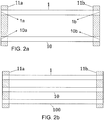
- FIG. 2b there is schematically shown the structure of the light permeable tubes comprised in a sensor according to the present disclosure.
- FIG. 2b there is shown how the end portions of three light permeable tubes 1, 10, 100 are attached to frame portions 11a and 11b.
- the sensor comprises however at least two spatially separated light permeable tubes 1, 10 having a first end 1a, 10a arranged on a first frame portion 11a and a second end 1b, 10b arranged on a second frame portion 11b of the robotic limb.
- the sensor also comprises a light detecting device 3, that can be connected to a processing unit 4 and that is arranged at a light detecting position of each of the light permeable tubes and that is configured to detect light emitted from a light emitting device 2 through the at least two light permeable tubes 1, 10 and also configured to transfer information comprising information relating to characteristics of the detected light to the processing unit 4.
- each light permeable tube provides for an independent degree of freedom when it comes to measurements and will as such provide unique information that can be processed to enable the positioning of a flexible element such as a robotic limb.
- the term light permeable tubes means that the light are allowed to propagate along the tubes from an inlet arranged at the first end 1a, 10a, to an outlet arranged at the second end 1b, 10b.
- the tubes could in certain embodiments be prepared in such a way that most of the light that hits the inside surface of the tube is reflected back towards the bulk of the tube.
- the frame portions 11a and 11b that constitutes the bases on which the light permeable tubes are attached are also the structures where the forces are applied. Directly on the frame portions for those cases where the sensor is free and indirectly when the sensor is embedded in an outer structure such as a flexible element, i.e. a robotic limb. In the latter case the applied force will be transferred on to the frame portion via the outer structure and should therefore be attached to the flexible element in a way that transfers the force as easy as possible.
- the sensor utilizes light permeable tubes. With the term light permeable tube is intended tubes whose interior allows light to propagate more or less freely. These tubes could, for example, be hollow tubes but they may also be more elaborate constructions such as optical fibers.
- the important feature of the tubes is however that they should allow light to propagate largely undisturbed within its interior.
- the tubes are preferably made of a flexible material, and they could be made out of light weighted carbon fibers or optical fibers being strengthened by an outer layer of a light-weight material such as carbon fiber.
- the tubes could be provided with electrically conducting means that allows current to be fed between the frame portions. They could also be partially provided with such means to provide for the possibility that current can be conducted along at least parts of the surface of the tubes. Examples of such means are electrically conducting stripes or electrically conducting material embedded in the material of the outer layer of the tubes.
- Such an embodiment provides a way to utilize a sensor within, for example, a robotic limb as both a sensor and as a current conductor. In this way the amount of wires and cables carrying currents can be reduced. This provides for the possibility of a more light-weighted robotic limb.
- appendix 1 and 2 there is provided an outline of how the detected light characteristics may be used to enable the positioning of a flexible element.
- a sensor for enabling positioning of a flexible element subject to applied forces comprises:
- the sensor By providing the sensor with a reference detector 30 it will be possible to ensure that certain initial light characteristics that are used for determining the bend of the light permeable tubes are given correct values. If, for example, light intensity is used as the light characteristic that enables the tube bends to be determined than, since the quantum efficiency of a light emitting diode depends on temperature, the initial light intensity may need to be adjusted in order to obtain a more accurate determination of the bend.
- This embodiment ensures that the input to the processing unit represents the actual light intensity of the light that is emitted through each of the at least two light permeable tubes 1, 10.
- a possible way to provide the reference detector with light is by utilizing a beam splitter arranged between the light emitting device(s) or light emitting source(s) and the tubes. Light emitted from a particular source will thereby be split into two beams, one propagating through the tube and the other being directed towards the reference detector 30.
- a sensor for enabling positioning of a flexible element subject to applied forces comprises:
- the sensor By providing several light emitting sources, or equivalently several light emitting devices, and corresponding light detecting devices that are tuned to emit and detect, respectively, light of a certain wavelength the sensor will be able to provide a more robust output. Moreover the inclusion of several light emitting sources and light emitting devices provide better redundancy is those cases where one of light emitting devices and/or one of the light detecting devices becomes non-operative, e.g. gets broken. In a particular embodiment it is possible to provide the processing unit 4 with instructions to perform an algorithm whereby the outputs from the different light detecting devices 3, 33, 333 are compared and the most viable is used to determine the bend of the light permeable tubes 1, 10.
- the number of light emitting devices 2, 22, 222 and corresponding light detecting devices 3, 33, 333 may moreover be an odd number larger than or equal three.
- the processing unit 4 with instructions to perform an algorithm whereby the outputs from the different light detecting devices 3, 33, 333 are compared and voting is performed to provide the most probable estimation of the bend of the light permeable tubes 1, 10.
- This comparison algorithm might in a particular case be based on a voting functionality whereby the most appropriate value is extracted from the several outputs of the various light emitting devices by means of a majority vote. This could for example be performed by means of a Field Programmable Gate Array, FPGA.
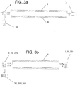
- FIG. 3b A particular embodiment of the proposed technology comprising three light emitting devices 2, 22, 222 and corresponding light detecting devices 3, 33, 333 is shown in FIG. 3b .
- a possible embodiment of a sensor comprising a plurality of light emitting devices 2, 22, 222 also comprises a beam splitter arranged between at least a subset of the light emitting devices 2, 2, 222 and a particular tube.
- the beam splitter is configured to collimate beams of light emitted from different light emitting devices and direct them towards a particular tube. It will in this way be possible to provide a single tube with light emitted from several different light emitting devices, by having corresponding detectors that detects characteristics of the light that has propagated through the tube, a single tube with beam splitter will therefor provide more information than a tube provided with light from a single source.
- the embodiment might also comprise beam splitters for the corresponding light detecting devices 3, 33, 333. That is, beam splitters are provided between the outlet of the tube and the light detecting devices 3, 33, 333
- the light emitting devices 2, 22,222 which might be regular light emitting diodes, could either be provided externally from the sensor or could be integrated into the sensor. In the case where they are arranged externally from the sensor they should be arranged on an outer element so that they can emit light into the light permeable tubes 1.
- Such an outer element could for example be the main robot body if the sensor is either incorporated in a robotic limb or if the sensor with its frame portions constitutes a robotic limb.
- All of the light permeable tubes could be provided with their own light emitting devices 2 dedicated to emit light through their allocated light permeable tube. It could however also be a single set of light emitting devices that are allocated to multiple light permeable tubes.
- Still another embodiment of the proposed technology provides a sensor for enabling positioning of a flexible element subject to applied forces.
- the sensor comprises:
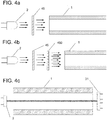
- FIG.4B An alternative embodiment is shown in FIG.4B , here two diffusion filters 45 are provided between the light emitting device and a tube. Having two or more filters arranged in succession renders the light even more
- the diffusion filter between the light emitting device(s) and the light detecting device it provides for a means whereby the light emanating from the light emitting sources enters the at least two spatially separated light permeable tubes 1, 10 in a more isotropic fashion.
- the variance of the Gaussian gets enhanced and the noise gets reduced, hence the light that enters the tube has a broader Gaussian shape. This in turn ensures that the light that enters the tube is more isotropic. This in particular reduces the risk that the detected light displays characteristics that are dependent on collimated light features.
- FIG.4a A particular embodiment of the proposed technology is illustrated in FIG.4a , here there is only shown a single light emitting device 2 and a diffusion filter 46 arranged between the light emitting device 3 and a single light permeable tube.
- This might however be generalized so that there is any number of light permeable tubes together with any number of light emitting devices, it could for example be a single, or only a few, light emitting device(s) for any number of tubes or as many light emitting devices as there are tubes or any other possible combination.
- FIG.4B An alternative embodiment is shown in FIG.4B , here two diffusion filters 45 and 450 are provided between the light emitting device and a tube. Having two or more filters arranged in succession renders the light that enters the tubes even more isotropic.
- Another version of a sensor might also be provided with diffusion filters arranged on the light detecting side of the tubes. In this way there is provided a sensor where the outgoing light passes through a diffusion filter before it is detected by the light detecting device. This will ensure that the detected light is isotropic when detected
- Yet another embodiment of the proposed technology provides a sensor for enabling positioning of a flexible element subject to applied forces.
- the sensor comprises:
- the proposed sensor provides a way whereby the bend of the tubes 1, 10 can be obtained by utilizing the detected light in each particular array element of the photodetector array.
- One embodiment of the array of the photodetectors comprises a linear array where a number of photodetectors are arranged along a line.
- Another embodiment relates to a case where the array is a two dimensional array whose surface is facing the end section of the corresponding tube. In other words, the two dimensional array comprises a number of photodetectors arranged in a matrix facing the end section of the corresponding tube.
- this array of photodetectors be a quadrant photodiode.
- this array of photodetectors be a quadrant photodiode.
- the upper quadrants detects a substantially larger amount of light it is highly likely that the tube has been bent downwards relative the quadrant photodiode.
- the use of a light emitting source in the form of a laser facilitates the use of a quadrant photodiode since the laser is not substantially effected by the inside surfaces of the tubes. This particular embodiment therefore provides a way to obtain more explicit, or fine grained, information about the light emitted through the tubes.
- This fine grained information that is extracted by means of the exposure of light on the various array elements in the photo diode array 31 will in turn enhance the precision with which the bend of the tubes can be determined. It may in particular reduce the number of light permeable tubes used in the sensor.
- a potential variation of a sensor that is able to provide a positioning of a flexible element comprises a sensor where a particular position of the tubes is provided with a glass element that at least partially covers the cross-section of the tube. Depending on the degree of bending of the tube this glass element will reflect different amounts of light, thereby providing a mechanism whereby the detected light intensity depends on the degree of bending of the tubes.
- the invention provides a sensor according to claim 1 for enabling positioning of a flexible element subject to applied forces.
- a schematic illustration of such a sensor is provided by FIG.5 .
- the joining means 120 should be preferably be of a type that allows the tubes to move or bend in a direction that is transversal to the frame portion containing the attachment point or attachment section. That is, if a tube are attached to a frame at a specific point then the joining means should provide for the possibility for the tube to be translationally fixed in the frame portion but allowed to rotate around its attachment point.
- the joining means 120 may for example be a joining means such as a spherical bearing or a universal joint. The use of joining means as a mechanism for attaching or fastening the tubes to the frame portions enables a highly efficient positioning of the flexible elements.
- a detected light intensity thereby provide a proper measure of the distance between the two frame portions.
- FIG.6 where a force has been applied to one of the frame portions 11a or 11b. The force has forced the frame portions closer to each other and the tube 10 has acquired a curvature or bend. Since the tube 10 are attached to the frame portions by means of joining means 120, such as a spherical bearings, the shape of the curvature takes the form of a half sine wave.
- a detection of the intensity of light having propagated through the tube 10 can thus be used to obtain a distance between two points on the tube, for example Px and Py in the figure, or the distance between the frame portions 11a and 11b.
- the distance between the frame portions 11a and 11b can then be used to position a flexible element that comprises the frame portions 11a and 11b. It can moreover be used to provide an orientation of a frame portion relative the other. This will be described more in what follows.
- a particular embodiment of a sensor comprising joining means 120 relates to a sensor where one of the frame portions 11a are fixed and the other frame portion 11b is allowed to rotate. If the end point of a tube 1 is attached to frame portion 11a in a fixed manner and the tube 1 is attached to the frame 11b by a joining means 120 that allows the end of the tube to rotate around its point of attachment, then a rotation of the frame portion 11b will lead to a torsion of the tube. This embodiment can be used to obtain a measure of the torsion.
- the joining means 120 may in this example be a universal joint. On the other hand, for this particular case, if the joining means 120 attaching tube 1 to frame portion 11b is a spherical bearing, there will be no torsion.
- different joining means 120 such as a spherical bearing at one end and a universal joint at the other.
- Another advantage with this particular embodiment is that it also counters potential skewing effects on the tubes which make the sensor more accurate since skewing effects might affect characteristics of light that propagates through a tube that has been skewed by applied forces or torques.
- This advantageous effect can be obtained by using a joining means 120 such as a spherical bearing, a cardan joint or a universal joint.
- the tubes will therefore be attached to the frames by these joining means.
- one of the ends of one light permeable tubes may be attached to a corresponding frame by means of such joining means 120.
- Another embodiment provides a sensor where each end of at least one tube 1, 10 are attached to the corresponding frame portion 11a, 11b by means of joining means 120.
- a particular embodiment provides a sensor where the joining means 120 comprises a spherical bearing or a universal joint.
- Still another embodiment provides a sensor where one end of at least one tube 1, 10 are attached to one frame portion by means of a spherical bearing and the other end of the at least one tube 1, 10 are attached to the other frame portion by means of a universal joint.
- Another embodiment is obtained by attaching all ends of all light permeable tubes by means of joining means 120.
- joining means 120 This is schematically shown in FIG.5 for the case of two light permeable tubes 1, 10.
- the joining means may differ from one end to another, for example a spherical bearing at one end and a universal joint at the other.
- Yet another embodiment of the proposed technology provides a sensor for enabling positioning of a flexible element subject to applied forces.
- the sensor comprises:
- each of the six spatially separated light tubes is equipped with its own set of light detecting devices 3 and light emitting devices 2. That is, a single tube in the set of tubes may be provided with a plurality of light emitting devices 2, 22, 222 and corresponding light detecting devices. Moreover, each of the six spatially separated tubes may also be provided with either one or a set of reference detectors 30 for each light emitting device. Still another embodiment comprises a sensor provided with a diffusion filter 45.
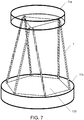
- Two especially useful planar configurations comprises six light permeable tubes wherein the fastening points of six light permeable tubes on one frame portion 11a are arranged to correspond to either the vertices of a triangle 124 or the vertices of a hexagon 123, and the fastening points of six light permeable tubes on the other frame portion 11b to either the vertices of a triangle 124 or the vertices of a hexagon 123 or a combination of them, see figures 7 , and 8 .
- the sides of the hexagon and triangle does not necessary have to be equal.
- Such a fastening pattern simplifies the computations needed to position the flexible element.
- at least one frame portion might be a modular frame portion where different modular sections acts as fastening structures for different sets of light permeable tubes, this is shown schematically in FIG 9 .
- a sensor comprising six tubes are particularly useful for a method, to be described below, that enables the determination of the orientation of a flexible element by utilizing detected light characteristics obtained by such a sensor.
- the flexible element being one of the frame portions 11a or 11b.
- a sensor comprising joining means 120 as described earlier with a light emitting device 3 that comprises a plurality of light emitting diodes, where each light emitting diode is configured to emit light of a pre-determined wavelength.
- a sensor comprising joining means 120 as described earlier might also comprise a reference detector 30 arranged in the vicinity of the light emitting device and being configured to detect light emitted from the light emitting device before the light enters the light permeable tubes 1, 10 to obtain reference values for certain light characteristics of the emitted light.
- Still another example of an embodiment provides a sensor having joining means 120 and also a beam-splitter arranged between a light emitting device 3 and a light permeable tube.
- the beam-splitter being configured to direct part of the light emitted from the light emitting device 3 to the reference detector 30.
- Yet another sensor comprising joining means 120 might comprise a diffusion filter () arranged between the light emitting device 3 and the light permeable tube 1.
- the senor having joining means might be provided with six spatially separated light permeable tubes 1, 10.
- Yet another version of a sensor comprising joining means 120 relates to a sensor where the number of light detecting devices 3 and light emitting devices 2 corresponds to the number of light permeable tubes and wherein each of the light detecting devices 3 and the light emitting devices are used for a designated light permeable tube 1, 10.
- Still another version of a sensor provided with joining means provide a sensor where the light emitting device 2 comprises a laser and where the light detecting device 3 comprises an array of light detecting devices 3.
- the proposed technology also provides a flexible element comprising a sensor according to the described embodiments.
- This flexible element might be a robotic limb that comprises the sensor.
- Still another embodiment, relevant for all earlier described embodiments provides a flexible element that also comprises a protective casing.
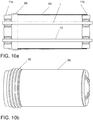
- FIG. 10a provides a schematic illustration of such a flexible element.
- the particular feature of a protective casing can be combined with all the earlier described embodiments.
- FIG. 10a discloses a flexible element comprising a sensor that comprises two light permeable tubes 1, 10 having their ends attached to frame portions 11a and 11b.
- the flexible element comprising the sensor are partially enclosed in a protective casing 65.
- the frame portions 11a and 11b of the sensor comprised in the flexible element should not be enclosed by the protective casing since they are supposed to be subjected to externally applied forces and torques.
- the number of light permeable tubes may vary, two is shown only to simplify the illustration.
- the protective casing 65 ensures that the possibly delicate tubes are protected from damage.
- the protective casing might furthermore comprise one or more elastic segments 66.
- the inclusion of an elastic segment 66 in the protective casing 65 will reduce the potential effect that vibrations induced from external sources have on the sensor.
- the protective casing 65 is preferably manufactured from a rather hard material to ensure that the interior is adequately protected from damaging effects. It is also preferred if the material is a light weight material to ensure that the use of the sensor in, for example, a robotic limb is energy efficient.
- the elastic segment 66 might, for example, be rubber or some other elastic material that can be bound to the protective casing 65.
- FIG.10b provides another illustration of the protective casing 65 with an elastic segment 66 where the internal components are hidden.
- the protective casing comprising the elastic segment could be attached to the flexible element comprising the sensor by attaching at least part of the casing to the frames 11a and 11b of the sensor.
- a flexible element comprising a protective casing 65 that is partially enclosing the flexible element.
- the protective casing might comprise at least one segment 66 of an elastic material.
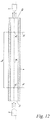
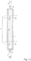
- the elastic segment may be arranged at one end of the protective casing as seen in FIG.10a but it might also be arranged at some other location such as in the middle of the casing, as illustrated in FIG 11a .
- An alternative view of a sensor comprising a protective casing 65 and elastic segment 66 is shown in FIG.11B .
- the proposed technology also provide a method that enables a determination of the position or the orientation of a moving frame portion 11a of a sensor subject to applied forces and torques.
- the sensor comprises:
- the invention provides a method that enables a determination of the position or the orientation of the moving frame portion of the sensor subject to forces and/or torques comprising:
- the method enables the determination of both the position and the orientation of the moving frame portion.
- the method may be used to first provide the positioning of the moving frame and then continue to provide the orientation of the moving frame relative the fixed frame by utilizing the determined position.
- the moving frame portion may correspond to the first frame portion 11a of the described sensor and the frame portion fixed relative the moving frame portion may correspond to the frame portion 11b of the described sensor.
- the method therefor provides a way to determine the orientation of frame portion 11a relative frame portion 11b and, as a consequence, the orientation of the sensor comprising frame portion 11a and frame portion 11b. It will thereby be possible to determine an orientation of a flexible element that comprises the sensor.
- the step S3 of determining the position and/or the orientation of the moving frame portion relative the fixed frame portion may in a particular embodiment be performed by means of a numerical kinematic method where the length values are used as input to the numerical kinematic method.
- a numerical kinematic method is a well-known method and may also be referred to as a numerical Newton method that utilizes Lagrange multipliers. A direct outline of the method can be found in REF 7. A detailed description of how this method may be used in a particular example will be given below.
- the conversion between the values of the detected light intensities and the specific length values is preferably performed by means of a look-up table.
- the content of the table containing pre-determined conversion factors whereby a particular detected intensity is mapped to a determined length value.
- the table content can be obtained experimentally by performing measurements where the value of the distances between frame portions 11a and 11b are known and where the intensities are measured. In this way will it be possible to provide a direct mapping between detected intensities and corresponding distances.
- the method is particularly useful for the case where the sensor comprises six light permeable tubes that extends between the frames of the flexible element, see any of FIGs 7-9 for an illustration of sensor that can be used to perform the method.
- This positioning method provides for a numerical kinematic method that can be used for a flexible element that is provided with six tubes that extends between the frames of the flexible element.
- the tubes will be fastened to the frames so that the fastening points lies in a common plane on each frame.
- the algorithm presented below displays robust convergence features if the fastening position of the tubes in the fixed frame correspond to the form of a hexagon and the fastening position of the tubes in the moving frame is provided in the form of a triangle, such as shown in FIG. 7 .
- the values g 16-21 creates rigidity constraints for the moving frame. These constraints looks different for each tube setup.
- the setup shown creates rigidity constraints for tubes fastening positions in the form of a triangle, where each pair of fastening positions at the edge of the triangle is at the exact same position.
- the limits for indices i and j has to be changed and the vector x k has to be expanded to hold all Lagrange multipliers ⁇ and the positions of all tube fastening positions in the moving frame.
- more constraints g i and squared distances h ij has to be added.
- the proposed method can in particular embodiments be performed by means of a computer program.
- the computer program comprises instructions, which when executed by at least one processor, cause the processor(s) to:
- the computer program may in particular convert the values of the detected light intensities to specific length values by means of reading from a pre-determined table providing a mapping between detected light intensities and specific length values.
- the computer program may also be provided with instructions that, when executed by at least one processor, cause the processor(s) to determine the orientation of the moving frame portion relative the fixed frame portion by using the length values as input in a numerical kinematic method.
- the proposed technology also provides a carrier comprising the computer program, wherein the carrier is one of an electronic signal, an optical signal, an electromagnetic signal, a magnetic signal, an electric signal, a radio signal, a microwave signal, or a computer-readable storage medium.
- the software or computer program may be realized as a computer program product, which is normally carried or stored on a computer-readable medium, in particular a non-volatile medium.
- the computer-readable medium may include one or more removable or non-removable memory devices including, but not limited to a Read-Only Memory (ROM), a Random Access Memory (RAM), a Compact Disc (CD), a Digital Versatile Disc (DVD), a Blu-ray disc, a Universal Serial Bus (USB) memory, a Hard Disk Drive (HDD) storage device, a flash memory, a magnetic tape, or any other conventional memory device.
- the computer program may thus be loaded into the operating memory of a computer or equivalent processing device for execution by the processing circuitry thereof.
- the computer program residing in memory may also be organized as appropriate function modules configured to perform, when executed by the processor, at least part of the steps and/or tasks described herein.
- the light detecting device(s) 3, 33, 333 of every light permeable tube 1 may be provided somewhere along the length of the light permeable tube 1. In one embodiment it is provided on the second end 1b of the light permeable tube 1. By placing it there it is easy for an operator to reach it which makes it easier to replace the light detecting device if it is broken. In another embodiment is the light detecting position provided somewhere along the length of the tube closer to frame portion 11b than frame portion 11a in the case that the light emitting device(s) 2, 22, 222 is provided at frame portion 11a. In still another embodiment is the light detecting position provided in near proximity to the light emitting device.
- the light permeable tube 1 provided with a mirror that reflects the emitted light that have propagated through the light permeable tube 1 back towards the light detecting device(s) 3, 33, 333.
- the mirror could in this case be provided at the second end 1b of the light permeable tube if the light emitting device(s) is provided at the first end 1a of the light permeable tube.
- the mirror could also be provided within the tubes at particular positions as described above in relation to the light detecting position. As can be seen is there a multitude of choices of where to position the light detecting device along the light permeable tubes. The common feature of all the possible positions is that they should be chosen so that the detected light has been able to propagate at least partially over the lengths of the light permeable tubes.
- the sensor is in another exemplary embodiment provided with a processing unit that is connected to the light detecting device(s).
- the processing unit 4 integrated with the sensor. That is, it forms part of the sensor.
- the processing unit 4 is, as earlier, configured to determine the bend of each of the at least two tubes in the sensor based on characteristics of the detected light.
- the processing unit thus takes as input information comprising information regarding light characteristics such as intensity and based on the input it determines the bend of the sensor
- the processing unit in both the case where it is integrated in the sensor or externally provided but connectable to the sensor, also provided with a determining unit.
- the determining unit is configured to determine the length between two reference points along each of the at least two light permeable tubes based on the determined bend of each of the light permeable tubes.
- two reference points, Pa and Pb, on each of the tubes used in the sensor are chosen in advance.
- the determining unit is configured to determine the length between these points. With lengths is here intended the Euclidean distance or the straight line connecting the points.
- the determining unit takes as input the measures of bends of the tubes and determine the lengths between the selected points Pa and Pb of each of the light permeable tubes used in the sensor.
- the point Pa are centrally located within light permeable tube 1, 10 and are arranged at a location where the end portion 1a, 10a of the light permeable tube approximately connects to the frame portion 11a.
- the point Pb should be chosen to be centrally located within the light permeable tube 1, 10 and located at a position along the tube that is approximately the position where the end portion 1b, 10b connects with the frame portion 11b.
- Other locations of the points Pa and Pb are however possible at the cost of computational complexity.
- the appendix provides an exemplary algorithm that can be used for this length determining step.
- a processing unit that comprises a computing unit.
- the computing unit is configured to compute, based on the determined lengths for each of the at least two light permeable tubes, a resulting vector corresponding to a vector directed from the frame portion 11a to the frame portion 11b. This unit therefore generates a vector that extends between the frame portions 11a and 11b.
- processing the inner surface of the tube by for example coating the surface with a coating or sanding it, so that the walls mostly reflects diffuse light the mirroring effects can be reduced making the bend estimation more precise.
- Another possible way to reduce the direct reflectivity is to provide the inside surface of the tube with soot. It is preferred if the chosen measure to reduce direct reflection does not lead to light polarization changing effects. In several embodiments of the sensor, embodiments that will be described below, is it preferable if the polarization of light stays constant during interactions between the light and the material of the light permeable tubes. It might be also be an advantage for computational reasons if the inner surface of the tube is more or less homogeneous. If the processing is made in a way that utilizes coatings or other materials so that the inner surface becomes homogenous and isotropic it is also possible to make the bend estimation for any particular direction by using only information on the relationship between bend and intensity readings for a single chosen direction. One possible way to obtain the features according to above is to sand the inner surface of the light permeable tubes and/or coat it with a silver paint.
- embodiments may be implemented in hardware, or in software for execution by suitable processing circuitry, or a combination thereof.
- Particular examples include one or more suitably configured digital signal processors and other known electronic circuits, e.g. discrete logic gates interconnected to perform a specialized function, or Application Specific Integrated Circuits (ASICs).
- digital signal processors and other known electronic circuits, e.g. discrete logic gates interconnected to perform a specialized function, or Application Specific Integrated Circuits (ASICs).
- ASICs Application Specific Integrated Circuits
- At least some of the steps, functions, procedures, modules and/or blocks described herein may be implemented in software such as a computer program for execution by suitable processing circuitry such as one or more processors or processing units.
- processing circuitry includes, but is not limited to, one or more microprocessors, one or more Digital Signal Processors (DSPs), one or more Central Processing Units (CPUs), video acceleration hardware, and/or any suitable programmable logic circuitry such as one or more Field Programmable Gate Arrays (FPGAs), or one or more Programmable Logic Controllers (PLCs).
- DSPs Digital Signal Processors
- CPUs Central Processing Units
- FPGAs Field Programmable Gate Arrays
- PLCs Programmable Logic Controllers
- processors including one or more processors.
- the processor(s) and memory are interconnected to each other to enable normal software execution.
- An optional input/output device may also be interconnected to the processor(s) and/or the memory to enable input and/or output of relevant data such as input parameter(s) and/or resulting output parameter(s).
- processor' should be interpreted in a general sense as any system or device capable of executing program code or computer program instructions to perform a particular processing, determining or computing task.
- the processing circuitry including one or more processors is thus configured to perform, when executing the computer program, well-defined processing tasks such as those described herein.
- the processing circuitry does not have to be dedicated to only execute the above-described steps, functions, procedure and/or blocks, but may also execute other tasks.
- one light emitting source or device such as a LED
- emitter such as a LED
- a light detector henceforth called detector
- P a and P b are located on the neutral axis N, see e.g. FIGs. 12 , 13 or 15 , of the tube at different positions where P a is closer to the emitter and P b is closer to the detector.
- I a and I b Two planes, S a and S b , is defined by the tangent of the tubes neutral axis in position P a and P b respectively.
- the intensity of the light shining through S a and S b in the orientation from the emitter to the detector is called I a and I b .
- ⁇ e , ⁇ t and ⁇ d is the light attenuation in the tube from the emitter to S a , from S a to S b and from S b to the detector correspondingly.
- the attenuation from S a to S b is therefore given by equation 2.
- ⁇ t I d / ⁇ e ⁇ d I e
- the tube is processed, through coatings or other means, so that light shining through S a with intensity I a can be detected by a detector at position P b with the same intensity for a constant level of bend of the tube, between S a and S b , from the tangent of the neutral axis in point P a or P b , regardless of the direction of the bend relative to the tubes neutral axis.
- the relation between at and the bend of the tube between S a and S b is specific to the processing technique and material of the tube's inside and can be tested experimentally or derived analytically if enough material specifications is given.
- the tube will attenuate light so that the curvature ⁇ of the bend of the tube between S a and S b , measured in radians, see FIG. 15 , can be related to the attenuation at for predetermined values of the other attenuations and material specifications in the sensor.
- ⁇ can be determined experimentally.
- ⁇ can also be related to the magnitude of a resultant force acting on the tube, creating the bend, when the acting point is in either S a or S b .
- the relation between ⁇ and the forces magnitude can also be determined experimentally.
- a polarizing film can be placed between the emitter and detector statically aligning it with the emitter around the tube's neutral axis.
- the detector can be made linearly polarized by putting a polarizing film between the emitter and detector statically aligning it with the detector around the tube's neutral axis.
- the proposed method relates to a sensor that comprises two tubes of equal length whose ends are attached to two solid frames.
- the fastening points in each frame are at equal length d from each frame's center.
- the frame portion 11a is fixed in space with the frame lengthwise running parallel to the x axis, see FIG. 14 . All bending motion will occur in the x-y plane by applying a force on the frame portion 11b.
- the exemplary algorithm used for 2D positioning of a flexible element can be divided into the following steps:
- the simplest setup for 3D positioning utilizes a sensor that comprises three tubes of equal length whose ends are attached to two solid frames.
- the fastening points in each frame are at equal length from the frames center.
- the three fastening points are angularly fixed to be equal between the tubes and the frames center.
- the frame portion 11a will be considered fixed in space parallel to the x-y plane. All bending motion results from the application of a force on frame portion 11b.
- the algorithm used for 3D positioning of the flexible element can be divided into the following steps:
Landscapes
- Physics & Mathematics (AREA)
- General Physics & Mathematics (AREA)
- Length Measuring Devices By Optical Means (AREA)
- Measurement Of The Respiration, Hearing Ability, Form, And Blood Characteristics Of Living Organisms (AREA)
Claims (15)
- Capteur permettant de positionner un élément souple soumis à des forces appliquées, le capteur comprend :au moins deux tubes perméables à la lumière (1, 10) séparés dans l'espace, chaque tube ayant une première extrémité (1a, 10a) disposée sur une première partie de cadre (11a) et une seconde extrémité (1b, 10b) disposée sur une seconde partie de cadre (11b) de l'élément souple, dans lequel au moins une de ladite première extrémité (1a, 10a) ou de ladite seconde extrémité (1b, 10b) d'au moins un tube perméable à la lumière (1, 10) est fixée à une partie de cadre correspondante (11a, 11b) au moyen d'un moyen de jonction (120) ; et dans lequel chacun desdits au moins deux tubes perméables à la lumière séparés dans l'espace comprend en outre,au moins un dispositif électroluminescent (2),au moins un dispositif de détection de lumière (3), pouvant être connecté à une unité de traitement (4), et disposé en une position de détection de lumière d'un tube perméable à la lumière (1, 10) correspondant et configuré pour détecter la lumière émise par ledit au moins un dispositif électroluminescent (2) à travers le tube perméable à la lumière (1, 10) correspondant et configuré pour transférer des informations comprenant des informations relatives à la lumière détectée à l'unité de traitement (4) afin de permettre à l'unité de traitement de déterminer une distance entre ladite première et ladite seconde partie de cadre.
- Capteur selon la revendication 1, dans lequel chaque extrémité d'au moins un tube (1, 10) est fixée à la partie de cadre correspondante (11a, 11b) au moyen du moyen de jonction (120).
- Capteur selon la revendication 1 ou 2, dans lequel ledit moyen de jonction (120) comprend un palier sphérique ou un joint universel.
- Capteur selon la revendication 3, dans lequel une extrémité d'au moins un tube (1, 10) est fixée au moyen d'un palier sphérique et l'autre extrémité de l'au moins un tube (1, 10) est fixée au moyen d'un joint universel.
- Capteur selon l'une quelconque des revendications 1 à 4, dans lequel ledit capteur comprend en outre un dispositif électroluminescent (3) comprenant une pluralité de diodes électroluminescentes, chaque diode électroluminescente étant configurée pour émettre de la lumière d'une longueur d'onde prédéterminée.
- Capteur selon l'une quelconque des revendications 1 à 5, dans lequel ledit capteur comprend en outre au moins un détecteur de référence (30, 350, 355), ledit au moins un détecteur de référence étant disposé à proximité du dispositif électroluminescent (2) et configuré pour détecter la lumière émise par le dispositif électroluminescent avant que ladite lumière pénètre dans lesdits tubes perméables à la lumière (1, 10) pour obtenir des valeurs de référence pour certaines caractéristiques de lumière de ladite lumière émise.
- Capteur selon la revendication 6, dans lequel le capteur comprend également un diviseur de faisceau disposé entre le dispositif électroluminescent (3) et le tube perméable à la lumière, ledit diviseur de faisceau étant configuré pour diriger une partie de la lumière émise par le dispositif électroluminescent (3) au détecteur de référence (30).
- Capteur selon l'une quelconque des revendications 1 à 7, dans lequel ledit capteur comprend en outre au moins un filtre de diffusion (45, 450) disposé entre le dispositif électroluminescent (3) et le tube perméable à la lumière (1).
- Capteur selon l'une quelconque des revendications 1 à 8, dans lequel ledit capteur comprend six tubes perméables à la lumière (1, 10) séparés dans l'espace.
- Capteur selon l'une quelconque des revendications 1 à 9, dans lequel le nombre de dispositifs de détection de lumière (3) et de dispositifs électroluminescents correspond au nombre de tubes perméables à la lumière et dans lequel chacun dudit dispositif de détection de lumière (3) et dudit dispositif électroluminescent (2) sont utilisés pour un tube perméable à la lumière (1, 10) désigné.
- Capteur selon l'une quelconque des revendications 1 à 10, dans lequel ledit dispositif électroluminescent (2) comprend un laser et dans lequel ledit dispositif de détection de lumière (3) comprend un réseau de dispositifs de détection de lumière (3).
- Elément souple comprenant un capteur selon l'une quelconque des revendications 1 à 11.
- Elément souple selon la revendication 12, dans lequel ledit élément souple comprend en outre un boîtier de protection (65) renfermant des parties de l'élément souple.
- Elément souple selon la revendication 13, dans lequel ledit boîtier de protection comprend au moins un segment (66) d'un matériau élastique.
- Procédé de détermination de l'orientation d'une partie de cadre mobile d'un élément souple en utilisant un capteur selon l'une quelconque des revendications 1 à 11, le procédé comprenant les étapes :d'obtention (S1) des valeurs des intensités lumineuses détectées pour la lumière se propageant à travers différents tubes perméables à la lumière ; etde conversion (S2) des valeurs obtenues des intensités lumineuses détectées en valeurs de longueur correspondantes représentant des distances particulières entre ladite partie de cadre mobile et une seconde partie de cadre dudit élément souple fixées par rapport à ladite partie de cadre mobile ;de détermination (S3) de la position et/ou de l'orientation de la partie de cadre mobile par rapport à la partie de cadre fixe en utilisant les valeurs de longueur comme entrées dans un procédé cinématique direct numérique.
Applications Claiming Priority (2)
| Application Number | Priority Date | Filing Date | Title |
|---|---|---|---|
| SE1550059A SE538575C2 (en) | 2015-01-22 | 2015-01-22 | Sensor and method enabling the determination of the position and orientation of a flexible element |
| PCT/SE2016/050040 WO2016118070A1 (fr) | 2015-01-22 | 2016-01-22 | Capteur et procédé permettant la détermination de la position et de l'orientation d'un élément souple |
Publications (3)
| Publication Number | Publication Date |
|---|---|
| EP3247975A1 EP3247975A1 (fr) | 2017-11-29 |
| EP3247975A4 EP3247975A4 (fr) | 2018-07-11 |
| EP3247975B1 true EP3247975B1 (fr) | 2019-07-24 |
Family
ID=56417468
Family Applications (1)
| Application Number | Title | Priority Date | Filing Date |
|---|---|---|---|
| EP16740474.8A Active EP3247975B1 (fr) | 2015-01-22 | 2016-01-22 | Capteur et procédé permettant la détermination de la position et de l'orientation d'un élément souple |
Country Status (4)
| Country | Link |
|---|---|
| US (1) | US10260913B2 (fr) |
| EP (1) | EP3247975B1 (fr) |
| SE (1) | SE538575C2 (fr) |
| WO (1) | WO2016118070A1 (fr) |
Families Citing this family (6)
| Publication number | Priority date | Publication date | Assignee | Title |
|---|---|---|---|---|
| US10839202B2 (en) | 2013-09-17 | 2020-11-17 | Medibotics | Motion recognition clothing with flexible optical sensors |
| CN106441136B (zh) * | 2016-09-27 | 2019-03-12 | 上海建工集团股份有限公司 | 矩形盾构掘进阶段全断面变形监测方法 |
| DE102019204618B4 (de) * | 2019-04-01 | 2021-03-18 | Leoni Kabel Gmbh | Überwachungssystem für ein biegeelastisches, strangförmiges Element sowie biegeelastisches, strangförmiges Element |
| CN109955234B (zh) * | 2019-04-25 | 2021-06-15 | 哈尔滨工业大学 | 一种柔性触手的形状检测系统及方法 |
| CN113297952B (zh) * | 2021-05-21 | 2022-06-24 | 哈尔滨工业大学(深圳) | 一种复杂环境下绳驱柔性机器人的测量方法和系统 |
| CN114460320B (zh) * | 2022-04-14 | 2022-06-21 | 深圳市帝迈生物技术有限公司 | 样本分析仪及其样本检测流程 |
Family Cites Families (21)
| Publication number | Priority date | Publication date | Assignee | Title |
|---|---|---|---|---|
| US5026141A (en) | 1981-08-24 | 1991-06-25 | G2 Systems Corporation | Structural monitoring system using fiber optics |
| US4542291A (en) | 1982-09-29 | 1985-09-17 | Vpl Research Inc. | Optical flex sensor |
| GB8531430D0 (en) | 1985-12-20 | 1986-02-05 | Rosemount Eng Co Ltd | Displacement sensing apparatus |
| DE4002293C2 (de) | 1990-01-26 | 1994-09-08 | Schenck Ag Carl | Vorrichtung zur Messung von Verformungen einer Probe in einer Prüfmaschine |
| US5633494A (en) | 1991-07-31 | 1997-05-27 | Danisch; Lee | Fiber optic bending and positioning sensor with selected curved light emission surfaces |
| AU6967094A (en) * | 1993-06-10 | 1995-01-03 | Lee A. Danisch | Fiber optic bending and positioning sensor |
| GB2286242A (en) | 1994-02-01 | 1995-08-09 | Timothy William Tod | Bending detection device |
| US5818982A (en) | 1996-04-01 | 1998-10-06 | Voss; Karl Friedrich | Fiber optic sensor based upon buckling of a freely suspended length of fiber |
| GB9713018D0 (en) | 1997-06-20 | 1997-08-27 | Secr Defence | Optical fibre bend sensor |
| GB2329243A (en) | 1997-09-05 | 1999-03-17 | Univ Portsmouth Enterprise | Optical force sensor for forces applied to the body |
| US6471710B1 (en) | 1999-08-13 | 2002-10-29 | Advanced Sensor Technology, Llc | Probe position sensing system and method of employment of same |
| CA2312691A1 (fr) | 2000-07-06 | 2002-01-06 | Mike Marcu | Ameliorations de systemes de detection de blocage de tube |
| AU2002349723A1 (en) * | 2002-11-27 | 2004-06-18 | Kinzo Kishida | Optical fiber measuring module |
| EP1635034B1 (fr) | 2004-08-27 | 2009-06-03 | Schlumberger Holdings Limited | Capteur et système de mesure pour déterminer le rayon de courbure et la forme d'un pipeline |
| JP4714570B2 (ja) | 2005-11-24 | 2011-06-29 | Hoya株式会社 | 内視鏡形状検出プローブ |
| US7930065B2 (en) | 2005-12-30 | 2011-04-19 | Intuitive Surgical Operations, Inc. | Robotic surgery system including position sensors using fiber bragg gratings |
| US9408530B2 (en) | 2006-04-12 | 2016-08-09 | Gearbox, Llc | Parameter-based navigation by a lumen traveling device |
| DE102006048635B4 (de) | 2006-10-13 | 2009-03-19 | Continental Automotive Gmbh | Faseroptischer Biegesensor und Verfahren zu dessen Herstellung |
| US8395109B2 (en) | 2010-05-25 | 2013-03-12 | The Jim Henson Company, Inc. | Motion sensor for detecting bending or pivoting |
| SE537516C2 (sv) * | 2013-07-29 | 2015-05-26 | Niklas Salomonsson | Metod och sensor för positionering av ett flexibelt element |
| US20150141768A1 (en) | 2013-10-24 | 2015-05-21 | The University Of Akron | Smart Fiber-Optic Sensor System and Method for Optical Spectroscopy in Robotic Surgical Systems |
-
2015
- 2015-01-22 SE SE1550059A patent/SE538575C2/en not_active IP Right Cessation
-
2016
- 2016-01-22 WO PCT/SE2016/050040 patent/WO2016118070A1/fr not_active Ceased
- 2016-01-22 EP EP16740474.8A patent/EP3247975B1/fr active Active
- 2016-01-22 US US15/545,564 patent/US10260913B2/en active Active
Non-Patent Citations (1)
| Title |
|---|
| None * |
Also Published As
| Publication number | Publication date |
|---|---|
| SE538575C2 (en) | 2016-09-27 |
| WO2016118070A1 (fr) | 2016-07-28 |
| EP3247975A1 (fr) | 2017-11-29 |
| SE1550059A1 (sv) | 2016-07-23 |
| US20170350733A1 (en) | 2017-12-07 |
| EP3247975A4 (fr) | 2018-07-11 |
| US10260913B2 (en) | 2019-04-16 |
Similar Documents
| Publication | Publication Date | Title |
|---|---|---|
| EP3247975B1 (fr) | Capteur et procédé permettant la détermination de la position et de l'orientation d'un élément souple | |
| JP6166436B2 (ja) | 光電式エンコーダ及びそのアライメント調整方法 | |
| CN105974427B (zh) | 结构光测距装置及方法 | |
| JP2901476B2 (ja) | 位置検出装置および位置検出方法 | |
| JP6382303B2 (ja) | 表面粗さ測定装置 | |
| CN113108720B (zh) | 一种基于线偏振光和条纹反射的表面三维重建方法 | |
| Aloi et al. | Estimating forces along continuum robots | |
| JP7319084B2 (ja) | 光学式変位計 | |
| US20230280451A1 (en) | Apparatus and method for calibrating three-dimensional scanner and refining point cloud data | |
| Deniz et al. | A solution to the hand-eye calibration in the manner of the absolute orientation problem | |
| Dolereit et al. | Underwater stereo calibration utilizing virtual object points | |
| CN107529941A (zh) | 弯曲信息导出装置、具有弯曲信息导出装置的内窥镜系统、弯曲信息导出方法和弯曲信息导出用的程序 | |
| CN109827607A (zh) | 线结构光焊缝跟踪传感器的标定方法及装置 | |
| US9921053B2 (en) | Method and sensor for positioning of a flexible element | |
| US9476708B2 (en) | Accelerometer based attitude determination | |
| JP5487920B2 (ja) | 光学式3次元形状計測装置及び光学式3次元形状計測方法 | |
| Senjalia et al. | Measurement of wheel alignment using Camera Calibration and Laser Triangulation | |
| Bogaerts et al. | A simple evaluation procedure for range camera measurement quality | |
| Rodríguez | Online self-calibration for mobile vision based on laser imaging and computer algorithms | |
| US20150015894A1 (en) | Determining geometric characteristics of reflective surfaces | |
| Hu et al. | Minimal vision system for linear camera self-calibration and 3D reconstruction using translation platform | |
| JP2891410B2 (ja) | 鏡面物体の三次元形状及び法線ベクトルの測定方法及び装置 | |
| Ha et al. | Calibration method for laser-camera scanners with a motorized rotating mechanism using a hand-eye calibration framework | |
| US8219274B2 (en) | 3-dimensional perception system and method for mobile platform | |
| Wang et al. | Refraction correction and calibration for planar structured light system in underwater environment: an improved ray tracing method based on projection and mapping |
Legal Events
| Date | Code | Title | Description |
|---|---|---|---|
| STAA | Information on the status of an ep patent application or granted ep patent |
Free format text: STATUS: THE INTERNATIONAL PUBLICATION HAS BEEN MADE |
|
| PUAI | Public reference made under article 153(3) epc to a published international application that has entered the european phase |
Free format text: ORIGINAL CODE: 0009012 |
|
| STAA | Information on the status of an ep patent application or granted ep patent |
Free format text: STATUS: REQUEST FOR EXAMINATION WAS MADE |
|
| 17P | Request for examination filed |
Effective date: 20170822 |
|
| AK | Designated contracting states |
Kind code of ref document: A1 Designated state(s): AL AT BE BG CH CY CZ DE DK EE ES FI FR GB GR HR HU IE IS IT LI LT LU LV MC MK MT NL NO PL PT RO RS SE SI SK SM TR |
|
| AX | Request for extension of the european patent |
Extension state: BA ME |
|
| DAV | Request for validation of the european patent (deleted) | ||
| DAX | Request for extension of the european patent (deleted) | ||
| A4 | Supplementary search report drawn up and despatched |
Effective date: 20180613 |
|
| RIC1 | Information provided on ipc code assigned before grant |
Ipc: B25J 18/06 20060101ALI20180607BHEP Ipc: G01B 11/24 20060101AFI20180607BHEP Ipc: G01D 5/26 20060101ALI20180607BHEP Ipc: G01B 11/16 20060101ALI20180607BHEP Ipc: G01B 11/255 20060101ALI20180607BHEP |
|
| GRAP | Despatch of communication of intention to grant a patent |
Free format text: ORIGINAL CODE: EPIDOSNIGR1 |
|
| STAA | Information on the status of an ep patent application or granted ep patent |
Free format text: STATUS: GRANT OF PATENT IS INTENDED |
|
| INTG | Intention to grant announced |
Effective date: 20190225 |
|
| GRAS | Grant fee paid |
Free format text: ORIGINAL CODE: EPIDOSNIGR3 |
|
| GRAA | (expected) grant |
Free format text: ORIGINAL CODE: 0009210 |
|
| STAA | Information on the status of an ep patent application or granted ep patent |
Free format text: STATUS: THE PATENT HAS BEEN GRANTED |
|
| AK | Designated contracting states |
Kind code of ref document: B1 Designated state(s): AL AT BE BG CH CY CZ DE DK EE ES FI FR GB GR HR HU IE IS IT LI LT LU LV MC MK MT NL NO PL PT RO RS SE SI SK SM TR |
|
| REG | Reference to a national code |
Ref country code: GB Ref legal event code: FG4D |
|
| REG | Reference to a national code |
Ref country code: CH Ref legal event code: EP |
|
| REG | Reference to a national code |
Ref country code: DE Ref legal event code: R096 Ref document number: 602016017391 Country of ref document: DE |
|
| REG | Reference to a national code |
Ref country code: AT Ref legal event code: REF Ref document number: 1158720 Country of ref document: AT Kind code of ref document: T Effective date: 20190815 |
|
| REG | Reference to a national code |
Ref country code: IE Ref legal event code: FG4D |
|
| REG | Reference to a national code |
Ref country code: CH Ref legal event code: NV Representative=s name: STOLMAR AND PARTNER INTELLECTUAL PROPERTY S.A., CH |
|
| REG | Reference to a national code |
Ref country code: NL Ref legal event code: MP Effective date: 20190724 |
|
| REG | Reference to a national code |
Ref country code: LT Ref legal event code: MG4D |
|
| REG | Reference to a national code |
Ref country code: AT Ref legal event code: MK05 Ref document number: 1158720 Country of ref document: AT Kind code of ref document: T Effective date: 20190724 |
|
| PG25 | Lapsed in a contracting state [announced via postgrant information from national office to epo] |
Ref country code: BG Free format text: LAPSE BECAUSE OF FAILURE TO SUBMIT A TRANSLATION OF THE DESCRIPTION OR TO PAY THE FEE WITHIN THE PRESCRIBED TIME-LIMIT Effective date: 20191024 Ref country code: NL Free format text: LAPSE BECAUSE OF FAILURE TO SUBMIT A TRANSLATION OF THE DESCRIPTION OR TO PAY THE FEE WITHIN THE PRESCRIBED TIME-LIMIT Effective date: 20190724 Ref country code: PT Free format text: LAPSE BECAUSE OF FAILURE TO SUBMIT A TRANSLATION OF THE DESCRIPTION OR TO PAY THE FEE WITHIN THE PRESCRIBED TIME-LIMIT Effective date: 20191125 Ref country code: AT Free format text: LAPSE BECAUSE OF FAILURE TO SUBMIT A TRANSLATION OF THE DESCRIPTION OR TO PAY THE FEE WITHIN THE PRESCRIBED TIME-LIMIT Effective date: 20190724 Ref country code: LT Free format text: LAPSE BECAUSE OF FAILURE TO SUBMIT A TRANSLATION OF THE DESCRIPTION OR TO PAY THE FEE WITHIN THE PRESCRIBED TIME-LIMIT Effective date: 20190724 Ref country code: HR Free format text: LAPSE BECAUSE OF FAILURE TO SUBMIT A TRANSLATION OF THE DESCRIPTION OR TO PAY THE FEE WITHIN THE PRESCRIBED TIME-LIMIT Effective date: 20190724 Ref country code: NO Free format text: LAPSE BECAUSE OF FAILURE TO SUBMIT A TRANSLATION OF THE DESCRIPTION OR TO PAY THE FEE WITHIN THE PRESCRIBED TIME-LIMIT Effective date: 20191024 Ref country code: FI Free format text: LAPSE BECAUSE OF FAILURE TO SUBMIT A TRANSLATION OF THE DESCRIPTION OR TO PAY THE FEE WITHIN THE PRESCRIBED TIME-LIMIT Effective date: 20190724 Ref country code: SE Free format text: LAPSE BECAUSE OF FAILURE TO SUBMIT A TRANSLATION OF THE DESCRIPTION OR TO PAY THE FEE WITHIN THE PRESCRIBED TIME-LIMIT Effective date: 20190724 |
|
| PG25 | Lapsed in a contracting state [announced via postgrant information from national office to epo] |
Ref country code: GR Free format text: LAPSE BECAUSE OF FAILURE TO SUBMIT A TRANSLATION OF THE DESCRIPTION OR TO PAY THE FEE WITHIN THE PRESCRIBED TIME-LIMIT Effective date: 20191025 Ref country code: IS Free format text: LAPSE BECAUSE OF FAILURE TO SUBMIT A TRANSLATION OF THE DESCRIPTION OR TO PAY THE FEE WITHIN THE PRESCRIBED TIME-LIMIT Effective date: 20191124 Ref country code: LV Free format text: LAPSE BECAUSE OF FAILURE TO SUBMIT A TRANSLATION OF THE DESCRIPTION OR TO PAY THE FEE WITHIN THE PRESCRIBED TIME-LIMIT Effective date: 20190724 Ref country code: RS Free format text: LAPSE BECAUSE OF FAILURE TO SUBMIT A TRANSLATION OF THE DESCRIPTION OR TO PAY THE FEE WITHIN THE PRESCRIBED TIME-LIMIT Effective date: 20190724 Ref country code: AL Free format text: LAPSE BECAUSE OF FAILURE TO SUBMIT A TRANSLATION OF THE DESCRIPTION OR TO PAY THE FEE WITHIN THE PRESCRIBED TIME-LIMIT Effective date: 20190724 Ref country code: ES Free format text: LAPSE BECAUSE OF FAILURE TO SUBMIT A TRANSLATION OF THE DESCRIPTION OR TO PAY THE FEE WITHIN THE PRESCRIBED TIME-LIMIT Effective date: 20190724 |
|
| PG25 | Lapsed in a contracting state [announced via postgrant information from national office to epo] |
Ref country code: TR Free format text: LAPSE BECAUSE OF FAILURE TO SUBMIT A TRANSLATION OF THE DESCRIPTION OR TO PAY THE FEE WITHIN THE PRESCRIBED TIME-LIMIT Effective date: 20190724 |
|
| PG25 | Lapsed in a contracting state [announced via postgrant information from national office to epo] |
Ref country code: RO Free format text: LAPSE BECAUSE OF FAILURE TO SUBMIT A TRANSLATION OF THE DESCRIPTION OR TO PAY THE FEE WITHIN THE PRESCRIBED TIME-LIMIT Effective date: 20190724 Ref country code: IT Free format text: LAPSE BECAUSE OF FAILURE TO SUBMIT A TRANSLATION OF THE DESCRIPTION OR TO PAY THE FEE WITHIN THE PRESCRIBED TIME-LIMIT Effective date: 20190724 Ref country code: EE Free format text: LAPSE BECAUSE OF FAILURE TO SUBMIT A TRANSLATION OF THE DESCRIPTION OR TO PAY THE FEE WITHIN THE PRESCRIBED TIME-LIMIT Effective date: 20190724 Ref country code: DK Free format text: LAPSE BECAUSE OF FAILURE TO SUBMIT A TRANSLATION OF THE DESCRIPTION OR TO PAY THE FEE WITHIN THE PRESCRIBED TIME-LIMIT Effective date: 20190724 Ref country code: PL Free format text: LAPSE BECAUSE OF FAILURE TO SUBMIT A TRANSLATION OF THE DESCRIPTION OR TO PAY THE FEE WITHIN THE PRESCRIBED TIME-LIMIT Effective date: 20190724 |
|
| PG25 | Lapsed in a contracting state [announced via postgrant information from national office to epo] |
Ref country code: CZ Free format text: LAPSE BECAUSE OF FAILURE TO SUBMIT A TRANSLATION OF THE DESCRIPTION OR TO PAY THE FEE WITHIN THE PRESCRIBED TIME-LIMIT Effective date: 20190724 Ref country code: SK Free format text: LAPSE BECAUSE OF FAILURE TO SUBMIT A TRANSLATION OF THE DESCRIPTION OR TO PAY THE FEE WITHIN THE PRESCRIBED TIME-LIMIT Effective date: 20190724 Ref country code: IS Free format text: LAPSE BECAUSE OF FAILURE TO SUBMIT A TRANSLATION OF THE DESCRIPTION OR TO PAY THE FEE WITHIN THE PRESCRIBED TIME-LIMIT Effective date: 20200224 Ref country code: SM Free format text: LAPSE BECAUSE OF FAILURE TO SUBMIT A TRANSLATION OF THE DESCRIPTION OR TO PAY THE FEE WITHIN THE PRESCRIBED TIME-LIMIT Effective date: 20190724 |
|
| REG | Reference to a national code |
Ref country code: DE Ref legal event code: R097 Ref document number: 602016017391 Country of ref document: DE |
|
| PLBE | No opposition filed within time limit |
Free format text: ORIGINAL CODE: 0009261 |
|
| STAA | Information on the status of an ep patent application or granted ep patent |
Free format text: STATUS: NO OPPOSITION FILED WITHIN TIME LIMIT |
|
| PG2D | Information on lapse in contracting state deleted |
Ref country code: IS |
|
| 26N | No opposition filed |
Effective date: 20200603 |
|
| PG25 | Lapsed in a contracting state [announced via postgrant information from national office to epo] |
Ref country code: MC Free format text: LAPSE BECAUSE OF FAILURE TO SUBMIT A TRANSLATION OF THE DESCRIPTION OR TO PAY THE FEE WITHIN THE PRESCRIBED TIME-LIMIT Effective date: 20190724 Ref country code: SI Free format text: LAPSE BECAUSE OF FAILURE TO SUBMIT A TRANSLATION OF THE DESCRIPTION OR TO PAY THE FEE WITHIN THE PRESCRIBED TIME-LIMIT Effective date: 20190724 |
|
| REG | Reference to a national code |
Ref country code: BE Ref legal event code: MM Effective date: 20200131 |
|
| PG25 | Lapsed in a contracting state [announced via postgrant information from national office to epo] |
Ref country code: LU Free format text: LAPSE BECAUSE OF NON-PAYMENT OF DUE FEES Effective date: 20200122 |
|
| PG25 | Lapsed in a contracting state [announced via postgrant information from national office to epo] |
Ref country code: BE Free format text: LAPSE BECAUSE OF NON-PAYMENT OF DUE FEES Effective date: 20200131 |
|
| PGFP | Annual fee paid to national office [announced via postgrant information from national office to epo] |
Ref country code: IE Payment date: 20201230 Year of fee payment: 6 |
|
| PGFP | Annual fee paid to national office [announced via postgrant information from national office to epo] |
Ref country code: CH Payment date: 20210120 Year of fee payment: 6 |
|
| PG25 | Lapsed in a contracting state [announced via postgrant information from national office to epo] |
Ref country code: MT Free format text: LAPSE BECAUSE OF FAILURE TO SUBMIT A TRANSLATION OF THE DESCRIPTION OR TO PAY THE FEE WITHIN THE PRESCRIBED TIME-LIMIT Effective date: 20190724 Ref country code: CY Free format text: LAPSE BECAUSE OF FAILURE TO SUBMIT A TRANSLATION OF THE DESCRIPTION OR TO PAY THE FEE WITHIN THE PRESCRIBED TIME-LIMIT Effective date: 20190724 |
|
| PG25 | Lapsed in a contracting state [announced via postgrant information from national office to epo] |
Ref country code: MK Free format text: LAPSE BECAUSE OF FAILURE TO SUBMIT A TRANSLATION OF THE DESCRIPTION OR TO PAY THE FEE WITHIN THE PRESCRIBED TIME-LIMIT Effective date: 20190724 |
|
| REG | Reference to a national code |
Ref country code: CH Ref legal event code: PL |
|
| PG25 | Lapsed in a contracting state [announced via postgrant information from national office to epo] |
Ref country code: LI Free format text: LAPSE BECAUSE OF NON-PAYMENT OF DUE FEES Effective date: 20220131 Ref country code: CH Free format text: LAPSE BECAUSE OF NON-PAYMENT OF DUE FEES Effective date: 20220131 |
|
| PG25 | Lapsed in a contracting state [announced via postgrant information from national office to epo] |
Ref country code: IE Free format text: LAPSE BECAUSE OF NON-PAYMENT OF DUE FEES Effective date: 20220122 |
|
| PGFP | Annual fee paid to national office [announced via postgrant information from national office to epo] |
Ref country code: GB Payment date: 20221230 Year of fee payment: 8 Ref country code: FR Payment date: 20221230 Year of fee payment: 8 |
|
| GBPC | Gb: european patent ceased through non-payment of renewal fee |
Effective date: 20240122 |
|
| PG25 | Lapsed in a contracting state [announced via postgrant information from national office to epo] |
Ref country code: GB Free format text: LAPSE BECAUSE OF NON-PAYMENT OF DUE FEES Effective date: 20240122 |
|
| PG25 | Lapsed in a contracting state [announced via postgrant information from national office to epo] |
Ref country code: FR Free format text: LAPSE BECAUSE OF NON-PAYMENT OF DUE FEES Effective date: 20240131 |
|
| PG25 | Lapsed in a contracting state [announced via postgrant information from national office to epo] |
Ref country code: GB Free format text: LAPSE BECAUSE OF NON-PAYMENT OF DUE FEES Effective date: 20240122 Ref country code: FR Free format text: LAPSE BECAUSE OF NON-PAYMENT OF DUE FEES Effective date: 20240131 |
|
| PGFP | Annual fee paid to national office [announced via postgrant information from national office to epo] |
Ref country code: DE Payment date: 20241218 Year of fee payment: 10 |