EP3248101B1 - Système informatique distribué avec clonage de base de données géré par ressources - Google Patents
Système informatique distribué avec clonage de base de données géré par ressources Download PDFInfo
- Publication number
- EP3248101B1 EP3248101B1 EP16701896.9A EP16701896A EP3248101B1 EP 3248101 B1 EP3248101 B1 EP 3248101B1 EP 16701896 A EP16701896 A EP 16701896A EP 3248101 B1 EP3248101 B1 EP 3248101B1
- Authority
- EP
- European Patent Office
- Prior art keywords
- instance
- database
- backup database
- cloning
- data
- Prior art date
- Legal status (The legal status is an assumption and is not a legal conclusion. Google has not performed a legal analysis and makes no representation as to the accuracy of the status listed.)
- Active
Links
Images


Classifications
-
- G—PHYSICS
- G06—COMPUTING OR CALCULATING; COUNTING
- G06F—ELECTRIC DIGITAL DATA PROCESSING
- G06F11/00—Error detection; Error correction; Monitoring
- G06F11/07—Responding to the occurrence of a fault, e.g. fault tolerance
- G06F11/14—Error detection or correction of the data by redundancy in operations
- G06F11/1446—Point-in-time backing up or restoration of persistent data
- G06F11/1448—Management of the data involved in backup or backup restore
-
- G—PHYSICS
- G06—COMPUTING OR CALCULATING; COUNTING
- G06F—ELECTRIC DIGITAL DATA PROCESSING
- G06F11/00—Error detection; Error correction; Monitoring
- G06F11/07—Responding to the occurrence of a fault, e.g. fault tolerance
- G06F11/14—Error detection or correction of the data by redundancy in operations
- G06F11/1446—Point-in-time backing up or restoration of persistent data
- G06F11/1458—Management of the backup or restore process
- G06F11/1464—Management of the backup or restore process for networked environments
-
- G—PHYSICS
- G06—COMPUTING OR CALCULATING; COUNTING
- G06F—ELECTRIC DIGITAL DATA PROCESSING
- G06F11/00—Error detection; Error correction; Monitoring
- G06F11/07—Responding to the occurrence of a fault, e.g. fault tolerance
- G06F11/14—Error detection or correction of the data by redundancy in operations
- G06F11/1446—Point-in-time backing up or restoration of persistent data
- G06F11/1458—Management of the backup or restore process
- G06F11/1461—Backup scheduling policy
-
- G—PHYSICS
- G06—COMPUTING OR CALCULATING; COUNTING
- G06F—ELECTRIC DIGITAL DATA PROCESSING
- G06F11/00—Error detection; Error correction; Monitoring
- G06F11/07—Responding to the occurrence of a fault, e.g. fault tolerance
- G06F11/14—Error detection or correction of the data by redundancy in operations
- G06F11/1446—Point-in-time backing up or restoration of persistent data
- G06F11/1458—Management of the backup or restore process
- G06F11/1469—Backup restoration techniques
-
- G—PHYSICS
- G06—COMPUTING OR CALCULATING; COUNTING
- G06F—ELECTRIC DIGITAL DATA PROCESSING
- G06F16/00—Information retrieval; Database structures therefor; File system structures therefor
- G06F16/20—Information retrieval; Database structures therefor; File system structures therefor of structured data, e.g. relational data
- G06F16/27—Replication, distribution or synchronisation of data between databases or within a distributed database system; Distributed database system architectures therefor
-
- G—PHYSICS
- G06—COMPUTING OR CALCULATING; COUNTING
- G06F—ELECTRIC DIGITAL DATA PROCESSING
- G06F16/00—Information retrieval; Database structures therefor; File system structures therefor
- G06F16/20—Information retrieval; Database structures therefor; File system structures therefor of structured data, e.g. relational data
- G06F16/27—Replication, distribution or synchronisation of data between databases or within a distributed database system; Distributed database system architectures therefor
- G06F16/275—Synchronous replication
-
- G—PHYSICS
- G06—COMPUTING OR CALCULATING; COUNTING
- G06F—ELECTRIC DIGITAL DATA PROCESSING
- G06F2201/00—Indexing scheme relating to error detection, to error correction, and to monitoring
- G06F2201/80—Database-specific techniques
Definitions
- the present disclosure is generally related to information technology, and in particular a distributed computing system programmed to perform data cloning operations.
- Modern computing systems often include large systems including multiple servers or processors communicating over local-area or wide-area networks serving multiple clients. These systems can store very large amounts of data and process many transactions in a given time period. Maintaining optimal system performance and the collection and analysis of transactional and dimensional data can be difficult or suboptimal in current systems.
- Metadata is received specifying inter-data correlation(s), inter-replica correlation(s), and data-replica correlation(s) among replicas generated for a system.
- a unified replication metadata model specifying the correlations is generated.
- one implementation comprises a computer-driven distributed data storage and management system embodied by multiple datacenters.
- the datacenters store and provide a primary database for access by remote customers.
- a standby database mirrors the primary database, and is available to quickly perform a failover operation.
- the data embodied in the primary and standby databases is referred to as a data source.
- the datacenters also store various backup database instances that duplicate the data source for us in case of error, loss, disaster, file corruption, equipment failure, and the like.
- Cloning refers to replication of a data source, database management software, and other applications, nodes, or instances required to provide the data source as a database. This disclosure provides a cloning process that minimizes or eliminates impact to the data source, reduces data copy time from data source to target instance, and optimizes data freshness and data copy time.
- Cloning is performed using a backup database corresponding to the primary and/or standby database. Before a cloning operation is carried out, one or more of the datacenters compare the freshness of the available backups. This comparison is configurable. Two backups are considered to have the same freshness if they were last updated within a given time, such as one hour, of each other.
- the clone target may reside in a different datacenter than clone source's datacenter. If two backups have the same freshness, then the datacenter of the source is selected so that data source is in the same datacenter as the target instance, or as physically proximate as possible.
- this disclosure sets forth a variety of improvements implemented before and during cloning.
- Cloud computing can provide various advantages over traditional computing models, including the ability to allocate shared resources amongst many different customers. Under traditional computing models, computing resources are typically allocated to a single customer or entity and substantial portions of those resources may remain unused or underused.
- Computing resources of cloud computing infrastructure may be allocated, for example, using a multi-tenant or a single-tenant architecture.
- a multi-tenant architecture installations or instantiations of application, database, and/or other software application servers may be shared amongst multiple customers.
- a single web server e.g., a unitary Apache installation
- application server e.g., unitary Java Virtual Machine
- database server catalog e.g., a unitary MySQL catalog
- data or applications used by various customers can be commingled or shared.
- the application and/or database server software can distinguish between and segregate data and other information of the various customers using the system. For example, database records belonging to a particular customer may be identified using a customer_id field in a database table holding records for numerous customers.
- each customer will access its dedicated web server(s), will have its transactions processed using its dedicated application server(s), and will have its data stored in its dedicated database server(s) and or catalog(s).
- physical hardware servers may be shared such that multiple installations or instantiations of web, application, and/or database servers may be installed on the same physical server. Each installation may be allocated a certain portion of the physical server resources, such as RAM, storage, and CPU cycles.
- a customer instance is composed of four web server instances, four application server instances, and two database server instances. As previously described each of these server instances may be located on different physical servers and each of these server instances may share resources of the different physical servers with a number of other server instances associated with other customer instances.
- the web, application, and database servers of the customer instance can be allocated to two different datacenters to facilitate high availability of the applications and data provided by the servers. There may be a primary pair of web servers and application servers in a first datacenter and a backup pair of web servers and application servers in a second datacenter. There may be a primary database server in the first datacenter and a second database server in the second datacenter. The primary database server can replicate data to the standby database server.
- the cloud computing infrastructure can be configured to direct traffic to the primary pair of web servers which can be configured to utilize the primary pair of application servers and primary database server respectively.
- the secondary servers may be converted to primary servers.
- the application servers can include a platform application, such as one written in Java, for example, that provides generic platform functionality for accessing the database servers, integrating with external applications, and rendering web pages and other content to be transmitted to clients.
- the generic platform functionality may be configured with metadata stored in the database server. In other words, the operation of the platform on the application server may be customized by certain end-users of the platform without requiring the Java code of the platform application to be changed.
- the database server instances can be configured with a database configuration and schema to facilitate the operation of the platform.
- the database server instance can be configured with various tables for storing metadata about applications, tables/fields, menus, forms, business rules, scripts, and custom UI elements that are used to customize the appearance and operation of the customer instance.
- the application servers can include web server functionality and the web servers can be omitted.
- a customer instance may include only two application servers and one database server.
- different implementations of customer instances may be used for different customer instances at the same time.
- Other configurations and implementations of customer instances may also be used.
- the proper allocation of computing resources of a physical server to an instance of a particular software server, such as a database server instance, can be important to the efficient and effective functioning of the cloud infrastructure. If too few resources are allocated, performance of the services provided to the customer using the database server may be degraded. If too many resources are allocated, computing resources may be wasted as the extra allocated resources may not meaningfully increase the performance of the services provided to the customer. Repeated over allocation of computing resources may require that additional server hardware be purchased to satisfy the over allocation, resulting in a greater than necessary cost for providing the cloud infrastructure.
- the amount of possible RAM may be constrained per physical server and the utilization of RAM may be relatively higher than other available computing resources, such as processing cycles (e.g., CPU) and storage (e.g., solid state and magnetic hard disks).
- processing cycles e.g., CPU
- storage e.g., solid state and magnetic hard disks
- the techniques and devices described herein may relate to the allocation of cloud computing resources, one aspect of which is the allocation of RAM resources to database servers installed on a particular physical server machine. An initial allocation of RAM to a database server may be generated and the database server may be provisioned using the initial allocation. Periodic measurements can be taken of the database server tables and buffer sizes and ratios are calculated.
- a desired memory allocation can be determined, for example using a pre-determined lookup table of memory allocation sizes to the calculated ratios.
- the desired memory allocation can be compiled in a report.
- the report can include functionality to permit a user to initiate an automated action to re-provision the database server using the desired memory allocation. Alternatively, the re-provisioning of the database server can be initiated automatically without user interaction.
- One implementation of this disclosure concerns a distributed computing system.
- FIG. 1 is a block diagram of an example distributed computing system 100.
- the system 100 includes a primary datacenter 110 and a secondary datacenter 120. A greater number of datacenters may be used, with two being shown for ease of explanation.
- the datacenters 110 are each coupled to a control center 102 by way of proxy load balancers 106.
- the control center 102 is linked to one or more clients 150.1, 150.2 (collectively or an example instance 150) via a telecommunications network 101. Broadly, the control center 102 directs operations of the datacenters 110.1, 110.2 on behalf of the clients 150. Some examples of these operations include hosting storage for the clients 150 and running applications for the clients 150.
- control center comprises a store and retrieve module and a cloning module, each containing algorithms that may be executed on a processor of the control center 102.
- system 100 may constitute an embodiment of cloud computing, performed on behalf of the clients 150.
- system 100 comprises a high availability system, where each data center 110 comprises a massively parallel execution engine.
- the control center 102 comprises at least one digital data processing machine. This is exemplified by a server, workstation, desktop computer, notebook computer, mainframe computer, datacenter, or other hardware appropriate to carry out the functionality described herein.
- the control center 102 is coupled to or includes storage 103 containing a predefined list of machine-readable orchestrations. Each orchestration names, represents, signifies, embodies, lists, or incorporates a set of machine-executable actions that carry out the orchestration. In an embodiment where the orchestrations do not contain the corresponding machine-executable actions, then the storage 103 may additionally contain the actions associated with each orchestration.
- the orchestrations may instead be provided in storage (not shown) outside of the control center 102 but nevertheless accessible by the control center 102.
- the storage 103 encompasses machine- readable storage devices and media of all types, as well as storage by virtue of being programmed into a circuitry such as an ASIC, FPGA, DSP, and such. Numerous examples of storage and logic circuits are explained in detail below.
- the control center 102 is also coupled to or includes a configuration management database (CMDB) 105.
- CMDB 105 comprises a database containing entries for the system's 100 information technology (IT) assets such as systems, software, facilities, products, network, storage, and the like. These assets, as represented in the CMDB 105, may be referred to as configuration items (CIs). Configuration item types may also include business types, such as organizations, people, markets, products, vendors, and partners.
- the CMDB 105 also describes the dependencies or other relationships among the configuration items. CMDBs are widely used, and many structural and operational details of the CMDB 105 will be apparent to those of ordinary skill in the relevant art, having the benefit of this disclosure.
- the control center 102 is linked to the clients 150 via the communications network 101.
- the network 101 may be implemented by any form of communication link that supports data exchange between the control center 102 and the clients 150 in satisfaction of the functions and purposes expressed herein.
- the network 101 may be configured as an overlay network, or a bus, mesh, tree, ring, star, peer-to-peer, overlay, or any combination or permutation of these or other known networks.
- the network 101 or one or more subcomponents thereof may include the public Internet or a corporate or government Intranet, for example.
- the network 101 may include one or more local area networks, wide area networks, Intranets, Extranets, Internetworks, Wi-Fi networks, or any other suitable technology using wires, radiofrequency, microwave, satellite, cellular, optical, or other telecommunications.
- the control center 102 is linked to the datacenters 110 by proxy load balancers 106.1-106.2.
- Each load balancer may be configured to direct traffic to respective servers and processing nodes located within its datacenter.
- the proxy-load balancers 106 may be configured to provide a single Internet-delivered service to remote clients via the network 101, where this service is actually provided by a server farm composed of the computerized servers of the datacenters 110.
- the components 106 also coordinate requests from remote clients to the datacenters 110, simplifying client access by masking the internal configuration of the datacenters.
- the components 106 may serve these functions by directing clients to processing nodes as configured directly or via DNS.
- the components 106 may be configured to direct traffic to the secondary datacenter in the event the primary datacenter 110 experiences one of many enumerated conditions predefined as failure.
- Each of the datacenters 110 includes a plurality of computerized servers.
- each datacenter 110 may be provided by one or more physical racks of computing machines.
- the datacenter 110.1 includes computerized servers 112.1A, 112.1B, and 112.1C
- the datacenter 110.2 includes computerized servers 112.2A, 112.2B, and 112.2C, although the number of servers may be increased or decreased in practice to suit the needs and context of the implementation.
- Each of the computerized servers comprises one or more digital processing machines. These may be exemplified by a server, workstation computer, or other hardware appropriate to carry out the functionality described herein, as described more fully below.
- the servers include client data storage as well as further storage containing machine-executable tasks. These stored instructions may be stored or programmed into the respective servers. For instance, the instructions may be contained in storage accessible by the computerized server, incorporated into circuitry of the computerized server, incorporated into code executable by the server, or other means.
- storage of the servers includes client data storage.
- An example of this is the primary database 132 in the datacenter 110.1, and the standby database 126 in the datacenter 110.2.
- the datacenters 110 operate in such a manner that the standby database 126 provides an exact or substantially exact mirror of the primary database 132.
- the data represented by the primary and standby databases 132, 126 are referred to as a data source or source instance.
- the datacenters 110 are programmed to conduct multiple backups of the data source. Some examples of these backups are illustrated at 113A-113C and 128. In practice, a greater or lesser number of backups may be implemented in practice, and some of these may reside in data centers that are provided in addition to the datacenters 110.
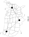
- the datacenters 110 and any further datacenters may be physically sited in geographically diverse locations.
- FIG. 8 is a map showing physical locations of datacenter hardware. As illustrated, datacenters 810 are located in geographically distinct sites across the United States 800.
- Each datacenter includes processing nodes such as 130 and 122, although a greater or lesser number may be implemented in practice.
- the nodes comprise processing threads, virtual machine instantiations, or other computing features of the datacenters that run programs on behalf of remotely sited clients, and exchange related data with such clients via the network 101.
- Some of the nodes may be dedicated to database management functions involving databases such as 132, 126.
- Each processing node runs an application program or conducts a database function on behalf of one of the remote clients 150 and according to directions of the control center 102.
- each node 130, 122 comprises virtual machine instantiation performing certain machine-executable actions.
- a node may comprise an application.
- a node may have its own operating system, or not, depending upon the implementation.
- the datacenters 110 include a messaging infrastructure, which may include one or more communications links, busses, backplanes, cables, wires, queues, buffers, networks, and/or other interconnection components.
- the messaging infrastructure is not shown, for ease of illustration of the other features of the system.
- the messaging infrastructure includes one or more interlinks such as 150 to support inter-datacenter communications.
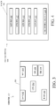
- FIG. 3 is a block diagram showing the hardware components of an example computerized server.
- the example computerized server 112 includes a storage enclosure 301 containing a storage area network (SAN) unit 302, networking hardware 304, CPU 202, and RAM 204.
- the computerized server 112 also includes one or more digital data storage devices which in this case are exemplified by hard disk drives 308.
- FIG. 4 is a block diagram showing the hardware components of an example datacenter.
- the example datacenter 400 includes a storage rack 402 containing various servers 112 and one or more network switches such as 414.
- the systems illustrated above include numerous components that may be implemented with data processing functionality. In any of these cases, such data processing features may be implemented by one or more instances of hardware, software, firmware, or a subcomponent or combination of the foregoing. Some example hardware of these subcomponents is described as follows.
- FIG. 2 is a block diagram of an example internal configuration of a computing device 200, such as a client 150 or server device 122 of the computing system 100 as shown in FIG. 1 , including an infrastructure control server, of a computing system.
- clients 150 or servers 122 may take the form of a computing system including multiple computing units, or in the form of a single computing unit, for example, a mobile phone, a tablet computer, a laptop computer, a notebook computer, a desktop computer, a server computer and the like.
- the computing device 200 can include a number of components, as illustrated in FIG. 2 .
- CPU (or processor) 202 can be a central processing unit, such as a microprocessor, and can include single or multiple processors, each having single or multiple processing cores.
- CPU 202 can include another type of device, or multiple devices, capable of manipulating or processing information now-existing or hereafter developed. When multiple processing devices are present, they may be interconnected in any manner, including hardwired or networked, including wirelessly networked. Thus, the operations of CPU 202 can be distributed across multiple machines that can be coupled directly or across a local area or other network
- the CPU 202 can be a general purpose processor or a special purpose processor.
- RAM 204 can be any suitable non-permanent storage device that is used as memory.
- RAM 204 can include executable instructions and data for immediate access by CPU 202.
- RAM 204 typically comprises one or more DRAM modules such as DDR SDRAM.
- RAM 204 can include another type of device, or multiple devices, capable of storing data for processing by CPU 202 now-existing or hereafter developed.
- CPU 202 can access and manipulate data in RAM 204 via bus 212.
- the CPU 202 may utilize a cache 220 as a form of localized fast memory for operating on data and instructions.
- Storage 206 can be in the form of read only memory (ROM), a disk drive, a solid state drive, flash memory, Phase-Change Memory (PCM), or any form of non-volatile memory designed to maintain data for some duration of time, and preferably in the event of a power loss.
- Storage 206 can include executable instructions 206A and application files/data 206B along with other data.
- the executable instructions 206A can include, for example, an operating system and one or more application programs for loading in whole or part into RAM 204 (with RAM-based executable instructions 204A and application files/data 204B) and to be executed by CPU 202.
- the executable instructions 206A may be organized into programmable modules or algorithms, functional programs, codes, and code segments designed to perform various functions described herein.
- module can be implemented using hardware, software, or a combination thereof.
- a module may form a part of a larger entity, and may itself be broken into sub-entities.
- this software can be implemented as algorithmic components comprising program instructions stored in a memory, the instructions designed to be executed on a processor.
- module does not require any specific form of coding structure, and functional aspects of different modules may be independent but also may overlap and be performed by common program instructions. For example, a first module and a second module may be implemented using a common set of program instructions without distinct boundaries between the respective and/or common instructions that implement the first and second modules.
- the operating system can be, for example, a Microsoft Windows ® , Mac OS X ® , or Linux ® , or operating system, or can be an operating system for a small device, such as a smart phone or tablet device, or a large device, such as a mainframe computer.
- the application program can include, for example, a web browser, web server and/or database server.
- Application files 206B can, for example, include user files, database catalogs and configuration information.
- storage 206 includes instructions to perform the discovery techniques described herein. Storage 206 may comprise one or multiple devices and may utilize one or more types of storage, such as solid state or magnetic.
- the computing device 200 can also include one or more input/output devices, such as a network communication unit 208 and interface 230 that may have a wired communication component or a wireless communications component 290, which can be coupled to CPU 202 via bus 212.
- the network communication unit 208 can utilized any of a variety of standardized network protocols, such as Ethernet, TCP/IP, to name a few of many protocols, to effect communications between devices.
- the interface 230 can comprise one or more transceiver(s) that utilize the Ethernet, power line communication (PLC), WiFi, infrared, GPRS/GSM, CDMA, etc.
- a user interface 210 can include a display, positional input device (such as a mouse, touchpad, touchscreen, or the like), keyboard, or other forms of user input and output devices.
- the user interface 210 can be coupled to the processor 202 via the bus 212.
- a graphical user interface (GUI) 210 is specifically a user interface that allows people to interact with a device in a graphical. It can be broken down into an input portion, an output portion, and a processor that manages, process, and interacts with the input and output portions.
- the input portion can accept input created by elements such as a mouse, touchpad, touchscreen, or the like.
- the output portion of a GUI can generate input displayable on some form of a display, such as a cathode-ray tube (CRT), liquid crystal display (LCD), and light emitting diode (LED) display, such as an organic light emitting diode (OLED) display.
- the display is generally formed of a grid of pixels, each of which can take on various illumination and optionally color values that are grouped together and arranged to form various higher-level entities (in pixel regions) on the display. These pixel regions can make up icons, windows, buttons, cursors, control elements, text, and other displayable entities.
- the display utilizes graphical device interface that typically comprises a graphics processor specifically designed to interact with the hardware of the display, and may accept high-level instructions from other processors to reduce demands on them.
- the graphical device interface typically has its own memory that serves as a buffer and also allows manipulation of stored data by the graphics processor. Operation of the display thus typically involves the graphics processor accessing instructions and data stored memory to modify pixel regions on the display for the user
- servers may omit display 210.
- RAM 204 or storage 206 can be distributed across multiple machines such as network-based memory or memory in multiple machines performing the operations of clients or servers.
- bus 212 can be composed of multiple buses, that may be connected to each other through various bridges, controllers, and/or adapters.
- Computing devices 200 may contain any number of sensors and detectors that monitor the device 200 itself or the environment around the device 200, or it may contain a location identification unit 260, such as a GPS or other type of location device.
- the computing device 200 may also contain a power source 270, such as a battery, so that the unit can operate in a self-contained manner. These may communicate with the CPU/processor 202 via the bus 212.
- computer may be used to refer to any of the digital data processing machines, devices, circuitry, instance, or embodiments discussed herein as well as those that will be apparent to those of ordinary skill in the relevant art having the benefit of this disclosure.
- the disclosed components include or utilize various instances of digital data storage.
- this digital data storage may be used for various functions, such as storing data and/or storing machine-readable instructions. These instructions may themselves aid in carrying out various processing functions, or they may serve to install a software program upon a computer, where such software program is thereafter executable to perform other functions related to this disclosure.
- the storage media may be implemented to digitally store machine-readable signals.
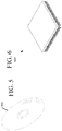
- optical storage such as CD-ROM, WORM, DVD, digital optical tape, optical disk storage 500 ( FIG. 5 ), or other optical storage.
- direct access storage such as a "hard drive”, redundant array of inexpensive disks (RAID), or another direct access storage device (DASD).
- serial-access storage such as magnetic or optical tape.
- digital data storage include electronic memory such as ROM, EPROM, flash PROM, EEPROM, memory registers, battery backed-up RAM, etc.
- An example storage medium is coupled to a processor so the processor may read information from, and write information to, the storage medium.
- the storage medium may be integral to the processor.
- the processor and the storage medium may reside in an ASIC or other integrated circuit.
- a different embodiment uses logic circuitry to implement some or all of the processing features described herein.
- this logic may be implemented by constructing an application-specific integrated circuit (ASIC) having thousands of tiny integrated transistors.
- ASIC application-specific integrated circuit
- Such an ASIC may be implemented with CMOS, TTL, VLSI, or another suitable construction.
- Other alternatives include a digital signal processing chip (DSP), discrete circuitry (such as resistors, capacitors, diodes, inductors, transistors, and the like), field programmable gate array (FPGA), programmable logic array (PLA), programmable logic device (PLD), and the like.
- DSP digital signal processing chip
- FPGA field programmable gate array
- PLA programmable logic array
- PLD programmable logic device
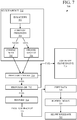
- FIG. 7 shows some example operations performed by a distributed computing system.
- the operations of any method, process, or algorithm described in connection with the embodiments disclosed herein may be embodied directly in hardware, firmware, software executed by hardware, circuitry, or a combination of these.
- the operations 700 are performed by the control center 102.
- the operations 700 concern preparation for, and execution of, a database cloning operation.
- the operations 700 are initiated in response to a command submitted by one of the clients 150.
- the operations 700 may be initiated by the control center 102 or one of the datacenters 110 in accordance with housekeeping, database maintenance, regular or irregularly schedule or spontaneous events, or other automated tasks performed in the distributed computing system 100.
- the operations 700 thus, may be initiated in response to receiving or detecting a prescribed command, event trigger, or any other occurrence.
- the client command, event trigger, or other causality that initiates data cloning specifies a data source to use in the cloning operation.
- the data source comprises the data represented by the primary database 132 and its mirrored copy at the standby database 126.
- the command also identifies a target storage site or instance, such as one of the servers of the datacenters 110, or a more particular storage site such as a storage device, storage address, or other site designation.
- the control center 102 will perform cloning using one of the backup database instances such as 113A-113C, 114, 128, etc.
- Operation 702 the control center 102 must select the particular backup database instance to be used as a source for the cloning operation.
- Operation 703 identifies the various available backup database instances whose data corresponds to the primary and secondary databases. This is carried out by the control center consulting the CMDB 105.
- Operation 704 compares the freshness of the various backup database instances, and namely, how recently they have been updated. In one implementation, the freshness of a backup database is indicated by the time that the most recent full or differential backup was performed to that database. To this end, operation 704 retrieves machine-readable records listing update times when the multiple backup database instances experienced updates from their data source. In one implementation, the backup times are listed in the CMDB 105.
- Operation 704 compares the differences in update times among the backup databases. If the most recently updated backup database instance was updated within a prescribed time period of one or more other backup database instance, then operation 704 treats these backup databases as having an equivalent update time. For example, if the most recent backup database instance was updated at 12:00 p.m. and subsequent backups occurred at 12:10 p.m. and 12:30 p.m., these will be treated as having equivalent freshness if the prescribed time period is set to one hour.
- the control center 102 is programmed to accept user selection, modification, or pre-configuration of the prescribed time period. One feature, then, is that the user may choose the time criteria for deeming backup databases to have the same freshness. If operation 704 answers "same," then operation 704 proceeds to operation 705.
- operation 705 selects the backup database instance that is the most proximate to a designated database instance.
- the designated database instance may comprise a testing instance such as instance 912, discussed below.
- the designated database instance may comprise the target site identified in the client command, event trigger, or other causality that initiated data cloning as discussed above.
- Proximity may comprise a physical proximity such as distance or geography, or a logical proximity such as residence within the same datacenter or server or other machine or virtual device or logical construct.
- a combination of physical and logical criteria may be used.
- proximity is expressing a preference to select a backup database instance from the same datacenter as the designated database instance, rather than a datacenter located across the country.
- this operation 705 operates according to proximity criteria preprogrammed into the control center.
- the control center 102 may be programmed to accept user selection, modification, or pre-configuration of the proximity criteria.
- One feature, then, is that the user may choose specify the level of preferred nearness of a selected backup database to the designated database instance.
- operation 706 chooses this backup database for the cloning operation, regardless of physical proximity to the designated database instance.
- Significantly more fresh means having an update time that is earlier by the prescribed time period or more.
- operations subsequent to 705-706 initiate cloning to the target storage site using the selected backup database instance as a "source" for the cloning.
- the selected backup database instance is considered a source instance for the target instance.
- operations 710-714 perform some preliminary operations.
- Operation 710 performs various so-called preflight checks. One example is verifying that the backup database instance, selected in 705 or 706, actually exists. In one implementation, if selected the backup instance is more than a given age, such as twenty-four hours, then the backup instance cannot be used and the preflight check 710 fails.
- Another example of the preflight checks of operation 710 comprises validating the backup database instance in the CMDB 105.
- CMDB 105 contains correct data for the clone source (backup data instance) and clone target (database being replaced) and data is not missing.
- Another example of the preflight checks of operation 710 includes verifying that the selected backup database instance is not stale with respect to its data source. If the primary database 132 was updated after the selected backup database instance, then the backup database instance is stale and operation 710 fails. One example of this is where the source schema has changed, which indicates that the backup data might not be able to be restored properly.
- Another example of the preflight checks of operation 710 includes determining whether automation can read the source and target version. If any of the preflight checks fail, then operation 710 proceeds to operation 716, which is described below.
- operation 712 provisions the target database instance. This involves appropriating storage hardware and other operations to ready the ultimate target database instance for access by clients 150.
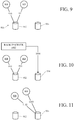
- FIGS. 9-11 are block diagrams of some example cloning sub operations.
- the system includes various testing instances, which are clones made from backups of the primary or secondary databases 132, 126. Each testing instance is a non-production instance available for the associated client 150 to experiment with different changes in configuration, software, data structures, and the like.
- FIG. 9 illustrates a testing instance 916 comprised of nodes 908, 909 and data 916. This provides one example context for conducting cloning, and namely, the purpose of cloning of a backup database (such as 113A-113C or 128) to provide a more current testing instance for use by the associated one of the clients 150.
- FIG. 9 illustrates the newly provisioned database at 914.
- the newly provisioned database 914 has the same size capacity as the testing instance 912. This reduces clone downtime and allows the customer to optionally roll back quickly after the clone is completed, as discussed below.
- operation 712 first attempts to provision to the same server as the testing instance 912, but if there is insufficient capacity, operation 712 attempts to complete the provisioning in the same datacenter as the testing instance. Provisioning a new database can fail due to capacity or other issues. In this case, operation 712 fails, and the operations proceed to operation 716, which is described below.
- operation 714 which conducts a restore operation from the selected backup database instance.
- the restore operation 714 includes unzipping the selected backup database instance and checking or verifying the backup data, metadata, and structure.
- the restore operation may be conducted using a program such as PERCONA XTRABACKUP, which is an open source hot backup utility for MySQL. Excluded tables may be filtered out as predefined by the system or specified by customer input. If the restore operation 714 fails, operation 716 is performed as described below. As mentioned above, if any of operations 710-714 fail, then the selected backup database cannot be safely used as a source for the cloning operation.
- cloning is conducted using an in-application cloning engine, as indicated by operation 716.
- the in-application cloning engine uses a node such as 130 or 122 to perform the requested clone directly from the primary 132 or standby 126 database, during which time the data remains available to the client.
- the in-application cloning operation may be referred to as a fallback operation.
- in-application cloning only as a fallback feature, this avoids using in-application engines to conduct clones unless this is necessary, thereby conserving processing and storage resources associated with the primary and secondary databases 132, 126. More particularly, this reduces resource usage on the data source, thereby reducing impact to other customer instances deployed to the same physical machine. This also reduces the amount of time required for the clone operation and the clone process workflow. Fallback reduces the duration of the impact to the end customer, among other benefits.
- Operation 718 begins the copying of data. In one implementation, this is performed by applying a data synchronization tool such as RSYNC to the target database instance that was provisioned in operation 712, and importing preserved data.
- a data synchronization tool such as RSYNC
- FIG. 10 depicts a backup server 1002 copying data to the newly provisioned database 914 via a link 1004.
- operation 720 performs a node repoint and version mismatch. Namely, operation720 severs or moves the links 910, 911 ( FIG. 10 ) from application nodes 908, 909, so that new links 1102, 1103 ( FIG. 11 ) link the nodes 908, 909 to the newly provisioned database 914, now populated with data from the backup server 1002 as explained above. If the testing instance 912 and the target instance 914 have different versions, operation 720 downloads and installs the version at the nodes 908, 909. Operation 720 also updates the target nodes' configuration file to use in the new database. Operation 720 further restarts the nodes 908, 909 to bring the target instance 914 online.
- Operation 722 is provided to show that, even after repointing the nodes in operation 720, the process 700 allows roll back for a given time.
- the testing instance 912 will be retired after twenty-four hours.
- the system may be configured such that this time period is client-configurable.
- the clone 914 is subject to being rolled back by repointing the target nodes 908, 909 to the old database 912.
- the old target database 912 is retired, and the cloning operation and process 700 are complete.
- Rollback may be initiated according to client request or a system event or condition.
- All or a portion of aspects of the invention described herein can be implemented using a general purpose computer/processor with a computer program that, when executed, carries out any of the respective techniques, algorithms and/or instructions described herein.
- a special purpose computer/processor can be utilized which can contain specialized hardware for carrying out any of the techniques, algorithms, or instructions described herein.
- the implementations of computing devices as described herein can be realized in hardware, software, or any combination thereof.
- the hardware can include, for example, computers, intellectual property (IP) cores, application-specific integrated circuits (ASICs), programmable logic arrays, optical processors, programmable logic controllers, microcode, microcontrollers, servers, microprocessors, digital signal processors or any other suitable circuit.
- IP intellectual property
- ASICs application-specific integrated circuits
- programmable logic arrays optical processors
- programmable logic controllers microcode, microcontrollers
- servers microprocessors, digital signal processors or any other suitable circuit.
- processors should be understood as encompassing any of the foregoing hardware, either singly or in combination.
- one or more computing devices can include an ASIC or programmable logic array such as a field-programmable gate array (FPGA) configured as a special-purpose processor to perform one or more of the operations or operations described or claimed herein.
- FPGA field-programmable gate array
- An example FPGA can include a collection of logic blocks and random access memory (RAM) blocks that can be individually configured and/or configurably interconnected in order to cause the FPGA to perform certain functions. Certain FPGA's may contain other general or special purpose blocks as well.
- An example FPGA can be programmed based on a hardware definition language (HDL) design, such as VHSIC Hardware Description Language or Verilog.
- HDL hardware definition language
- the aspects herein may be described in terms of functional block components and various processing operations. Such functional blocks may be realized by any number of hardware and/or software components that perform the specified functions.
- the described aspects may employ various integrated circuit components, e.g., memory elements, processing elements, logic elements, look-up tables, and the like, which may carry out a variety of functions under the control of one or more microprocessors or other control devices.
- the elements of the described aspects are implemented using software programming or software elements the invention may be implemented with any programming or scripting language such as C, C++, Java, assembler, or the like, with the various algorithms being implemented with any combination of data structures, objects, processes, routines or other programming elements.
- Functional aspects may be implemented in algorithms that execute on one or more processors.
- aspects of the invention could employ any number of conventional techniques for electronics configuration, signal processing and/or control, data processing and the like.
- the words “mechanism” and “element” are used broadly and are not limited to mechanical or physical embodiments or aspects, but can include software routines in conjunction with processors, etc.
- Implementations or portions of implementations of the above disclosure can take the form of a computer program product accessible from, for example, a computer-usable or computer-readable medium.
- a computer-usable or computer-readable medium can be any device that can, for example, tangibly contain, store, communicate, or transport a program or data structure for use by or in connection with any processor.
- the medium can be, for example, an electronic, magnetic, optical, electromagnetic, or a semiconductor device. Other suitable mediums are also available.
- Such computer-usable or computer-readable media can be referred to as non-transitory memory or media, and may include RAM or other volatile memory or storage devices that may change over time.
- a memory of an apparatus described herein, unless otherwise specified, does not have to be physically contained by the apparatus, but is one that can be accessed remotely by the apparatus, and does not have to be contiguous with other memory that might be physically contained by the apparatus.
- computational code may be implemented in the form of one or more modules by which individual or combined functions can be performed as a computational tool, the input and output data of each module being passed to/from one or more further module during operation of the methods and systems described herein.
- Information, data, and signals may be represented using a variety of different technologies and techniques.
- any data, instructions, commands, information, signals, bits, symbols, and chips referenced herein may be represented by voltages, currents, electromagnetic waves, magnetic fields or particles, optical fields or particles, other items, or a combination of the foregoing.
Landscapes
- Engineering & Computer Science (AREA)
- Theoretical Computer Science (AREA)
- Physics & Mathematics (AREA)
- General Engineering & Computer Science (AREA)
- General Physics & Mathematics (AREA)
- Databases & Information Systems (AREA)
- Quality & Reliability (AREA)
- Computing Systems (AREA)
- Data Mining & Analysis (AREA)
- Information Retrieval, Db Structures And Fs Structures Therefor (AREA)
Claims (15)
- Système de stockage et de gestion de données distribués piloté par ordinateur (100) pour le clonage d'instances de base de données, comprenant :de multiples centres de données (110) comprenant des premier et second centres de données (110.1, 110.2) :chacun des centres de données comprenant une pluralité de serveurs informatiques (112) et un dispositif de stockage de données numériques ;chacun des serveurs comprenant un processeur de données numériques couplé au dispositif de stockage de données numériques ;le dispositif de stockage de données numériques du premier centre de données comprenant une base de données primaire (132) ;le dispositif de stockage de données numériques du second centre de données comprenant une base de données de secours (126) ;des instances de base de données de sauvegarde (113, 128) construites en copiant des données à partir d'une source de données correspondante comprenant la base de données primaire ou de secours ; etun centre de commande (102) couplé aux centres de données comprenant un processeur, une mémoire (103), un module de stockage et de récupération, un module de clonage et d'autres modules, les modules comprenant des instructions stockées dans la mémoire qui s'exécutent sur le processeur pour exécuter les opérations ;le module de stockage et de récupération dirigeant les centres de données, y compris le fonctionnement de la base de données primaire pour stocker et récupérer des données pour le compte de clients à distance (150), et le fonctionnement de la base de données de secours pour refléter la base de données primaire à utiliser lors d'un événement de basculement ;le module de clonage, en réponse à la réception ou à la détection d'une commande, d'un déclencheur d'événement ou d'une autre occurrence prescrite :identifie une pluralité des instances de base de données de sauvegarde et récupère des enregistrements lisibles par machine répertoriant les temps de mise à jour lorsque chacune des instances de base de données de sauvegarde identifiées les plus récemment a connu une mise à jour à partir de la source de données correspondante de l'instance de base de données de sauvegarde ;en réponse à une première instance de base de données de sauvegarde identifiée ayant un temps de mise à jour dans une période prescrite d'une seconde instance de base de données de sauvegarde identifiée, où la première instance de base de données de sauvegarde identifiée est la plus récemment mise à jour des instances de base de données de sauvegarde identifiées, sélectionne, comme instance source pour le clonage, la première ou la seconde instance de base de données de sauvegarde identifiée satisfaisant à un critère de proximité prescrit par rapport à une instance de base de données désignée ;en réponse à une différence dans les temps de mise à jour supérieure à la période prescrite pour deux instances de base de données de sauvegarde identifiées faisant l'objet des mises à jour les plus récentes, sélectionne, comme instance source pour le clonage, la première instance de base de données et clone l'instance de base de données de sauvegarde sélectionnée vers une instance cible (914).
- Système selon la revendication 1, le centre de commande recevant et mettant en œuvre la configuration utilisateur de la période prescrite.
- Système selon la revendication 1 ou 2, le centre de commande recevant et mettant en œuvre la configuration utilisateur des critères de proximité prescrits.
- Système selon la revendication 3, le critère de proximité comprenant une proximité physique.
- Système selon la revendication 3 ou 4, le critère de proximité comprenant une proximité logique.
- Système selon l'une quelconque des revendications précédentes, les critères de proximité prescrits favorisant des instances de base de données de sauvegarde partageant un centre de données commun en tant qu'instance de données désignée.
- Système selon l'une quelconque des revendications précédentes :avant le clonage, le centre de commande conduit des opérations préparatoires comprenant la réalisation de vérifications en amont prescrites, le provisionnement de l'instance cible et la restauration de l'instance de base de données de sauvegarde sélectionnée vers l'instance cible provisionnée ; eten réponse à l'échec de l'une quelconque des opérations préparatoires, plutôt que de cloner l'instance de base de données de sauvegarde sélectionnée, le centre de contrôle clone uniquement les nœuds de traitement associés à la base de données primaire ou de secours pour copier les données directement à partir de la base de données primaire ou de secours.
- Système selon l'une quelconque des revendications précédentes :avant le clonage, le centre de commande conduit des opérations préparatoires comprenant la réalisation de vérifications en amont prescrites, le provisionnement de l'instance cible et la restauration de l'instance de base de données de sauvegarde sélectionnée vers l'instance cible provisionnée ; eten réponse au succès des opérations préparatoires, le centre de commande ne clone que les nœuds de traitement non associés aux bases de données primaire et de secours.
- Système selon la revendication 7 ou 8, les vérifications en amont prescrites comportant la vérification que l'instance de base de données de sauvegarde sélectionnée existe.
- Système selon l'une quelconque des revendications 7 à 9, les vérifications en amont comprenant la validation de l'instance de base de données de sauvegarde et de l'instance cible dans une base de données de gestion de configuration (105).
- Système selon l'une quelconque des revendications 7 à 10, les vérifications en amont comprenant la vérification que l'instance de base de données de sauvegarde sélectionnée peut être restaurée avec succès.
- Système selon l'une quelconque des revendications précédentes, l'instance de base de données désignée comprenant une instance de base de données de sauvegarde créée précédemment à remplacer par l'instance cible.
- Système selon l'une quelconque des revendications précédentes, l'instance de base de données désignée comprenant une instance de test (912), et l'instance de test étant remplacée par l'instance cible.
- Système selon l'une quelconque des revendications précédentes, le clonage comprenant :le provisionnement de l'instance cible ;la copie des données de l'instance de base de données de sauvegarde sélectionnée vers l'instance cible provisionnée ; etle re-pointage des nœuds d'application (908, 909) liés à une instance de base de données de sauvegarde précédemment créée de sorte que les nœuds d'application sont liés à l'instance cible provisionnée.
- Système selon la revendication 14, le centre de commande étant programmé pour permettre la restauration de l'instance cible vers l'instance de base de données de sauvegarde précédemment créée pendant une période de temps donnée après le clonage.
Applications Claiming Priority (2)
| Application Number | Priority Date | Filing Date | Title |
|---|---|---|---|
| US201562106796P | 2015-01-23 | 2015-01-23 | |
| PCT/US2016/013044 WO2016118361A1 (fr) | 2015-01-23 | 2016-01-12 | Système informatique distribué avec clonage de base de données géré par ressources |
Publications (2)
| Publication Number | Publication Date |
|---|---|
| EP3248101A1 EP3248101A1 (fr) | 2017-11-29 |
| EP3248101B1 true EP3248101B1 (fr) | 2021-12-08 |
Family
ID=55237921
Family Applications (1)
| Application Number | Title | Priority Date | Filing Date |
|---|---|---|---|
| EP16701896.9A Active EP3248101B1 (fr) | 2015-01-23 | 2016-01-12 | Système informatique distribué avec clonage de base de données géré par ressources |
Country Status (5)
| Country | Link |
|---|---|
| US (3) | US9460181B2 (fr) |
| EP (1) | EP3248101B1 (fr) |
| AU (3) | AU2016209679A1 (fr) |
| CA (2) | CA2974644C (fr) |
| WO (1) | WO2016118361A1 (fr) |
Families Citing this family (31)
| Publication number | Priority date | Publication date | Assignee | Title |
|---|---|---|---|---|
| US10339128B2 (en) * | 2016-05-17 | 2019-07-02 | International Business Machines Corporation | Verifying configuration management database configuration items |
| US20180032409A1 (en) * | 2016-07-26 | 2018-02-01 | Netapp, Inc. | Backup and recovery of application data of an application executing in a virtual machine |
| US10997216B1 (en) * | 2017-04-18 | 2021-05-04 | United Services Automobile Association (Usaa) | Systems and methods for centralized database cluster management |
| US11126600B2 (en) * | 2017-04-24 | 2021-09-21 | Reniac, Inc. | System and method to accelerate compaction |
| US10592530B2 (en) * | 2018-01-23 | 2020-03-17 | Vmware, Inc. | System and method for managing transactions for multiple data store nodes without a central log |
| US10802920B2 (en) * | 2018-04-18 | 2020-10-13 | Pivotal Software, Inc. | Backup and restore validation |
| US11468060B2 (en) * | 2018-06-25 | 2022-10-11 | Oracle International Corporation | Automatic query offloading to a standby database |
| CN109063135B (zh) * | 2018-08-03 | 2021-08-06 | 中国人民银行清算总中心 | 一种基于多活分布式架构的数据库复制方法及系统 |
| US11449327B2 (en) * | 2018-11-30 | 2022-09-20 | Paccar Inc | Error-resilient over-the-air software updates for vehicles |
| CN110209534B (zh) * | 2019-06-14 | 2022-09-16 | 四川长虹电器股份有限公司 | 自动备份mysql数据库的系统及方法 |
| CN110489397A (zh) * | 2019-08-09 | 2019-11-22 | 上海富欣智能交通控制有限公司 | 数据存储方法、装置及系统 |
| US10606585B1 (en) * | 2019-11-12 | 2020-03-31 | Capital One Services, Llc | Computer-based systems configured for automated roll-forward of software package versions and methods of use thereof |
| CN111158958B (zh) * | 2019-12-31 | 2020-11-13 | 广州鼎甲计算机科技有限公司 | 一种可快速恢复数据的备份方法、系统、装置及存储介质 |
| US11275790B2 (en) | 2019-12-31 | 2022-03-15 | Servicenow, Inc. | Enhanced phrase scoring for textual search |
| CN111240897B (zh) * | 2020-01-07 | 2023-04-14 | 腾讯科技(深圳)有限公司 | 一种数据处理方法及相关设备 |
| CN111629226A (zh) * | 2020-05-15 | 2020-09-04 | 上海幕革科技有限公司 | 一种基于中心存储的数据处理设备及其处理方法 |
| CN112000733B (zh) * | 2020-07-17 | 2024-08-09 | 杭州海康威视数字技术股份有限公司 | 图数据存储的方法和装置 |
| CN112433875B (zh) * | 2020-11-23 | 2024-07-16 | 京东科技控股股份有限公司 | 基于中间件的数据库运行方法、装置及终端设备 |
| CN112540875B (zh) * | 2020-12-11 | 2023-06-06 | 四川新网银行股份有限公司 | 一种基于xtrabackup的mysql数据库备份、恢复校验可用性的方法 |
| CN113505073B (zh) * | 2021-07-15 | 2024-07-26 | 北京金山云网络技术有限公司 | 一种数据库的性能测试方法、装置、设备及介质 |
| CN113590589B (zh) * | 2021-07-30 | 2025-02-14 | 中国工商银行股份有限公司 | 数据库搭建方法、装置及电子设备 |
| CN115878587A (zh) * | 2021-09-26 | 2023-03-31 | 中国联合网络通信集团有限公司 | 实例创建方法、装置、电子设备及可读存储介质 |
| US12050620B2 (en) | 2021-11-11 | 2024-07-30 | Oracle International Corporation | Optimized synchronization for redirected standby DML commands |
| CN116244316B (zh) * | 2022-12-26 | 2025-11-21 | 武汉中海庭数据技术有限公司 | 点云数据差异化加载方法、系统、介质及设备 |
| US12164542B1 (en) | 2023-07-05 | 2024-12-10 | The Toronto-Dominion Bank | Systems and methods for synchronization of data |
| CN117033087B (zh) * | 2023-10-10 | 2024-01-19 | 武汉吧哒科技股份有限公司 | 数据处理方法、装置、存储介质及管理服务器 |
| US12511200B2 (en) | 2023-10-27 | 2025-12-30 | Dell Products L.P. | Scheduling backups on a standby database in a high-availability configuration |
| US12292801B1 (en) * | 2023-10-27 | 2025-05-06 | Dell Products L.P. | Scheduling backups on a primary database in a high-availability configuration |
| US12566676B2 (en) | 2023-10-27 | 2026-03-03 | Dell Products L.P. | Enforcing full backup when role switch occurs in a database in a high-availability configuration |
| CN117170941B (zh) * | 2023-11-02 | 2024-02-13 | 建信金融科技有限责任公司 | 数据备份的方法、装置、电子设备和存储介质 |
| CN119342060B (zh) * | 2024-12-16 | 2025-03-14 | 温州天勤网络科技有限公司 | 一种云手机多机克隆跨区域数据传输的方法和系统 |
Citations (1)
| Publication number | Priority date | Publication date | Assignee | Title |
|---|---|---|---|---|
| US20060080362A1 (en) * | 2004-10-12 | 2006-04-13 | Lefthand Networks, Inc. | Data Synchronization Over a Computer Network |
Family Cites Families (73)
| Publication number | Priority date | Publication date | Assignee | Title |
|---|---|---|---|---|
| US5684984A (en) | 1994-09-29 | 1997-11-04 | Apple Computer, Inc. | Synchronization and replication of object databases |
| US9239763B2 (en) | 2012-09-28 | 2016-01-19 | Oracle International Corporation | Container database |
| US6560649B1 (en) | 1999-02-10 | 2003-05-06 | Avaya Technology Corp. | Hierarchical service level remediation for competing classes based upon achievement of service level goals |
| US6321229B1 (en) | 1999-02-26 | 2001-11-20 | Hewlett-Packard Company | Method and apparatus for using an information model to organize an information repository into a hierarchy of information |
| US6892221B2 (en) | 2000-05-19 | 2005-05-10 | Centerbeam | Data backup |
| US6816898B1 (en) | 2000-08-16 | 2004-11-09 | Proactivenet, Inc. | Interfacing external metrics into a performance management system |
| US6895586B1 (en) | 2000-08-30 | 2005-05-17 | Bmc Software | Enterprise management system and method which includes a common enterprise-wide namespace and prototype-based hierarchical inheritance |
| US7027411B1 (en) | 2000-10-31 | 2006-04-11 | Hewlett-Packard Development Company, L.P. | Method and system for identifying and processing changes to a network topology |
| US6944630B2 (en) | 2000-11-22 | 2005-09-13 | Bmc Software | Database management system and method which monitors activity levels and determines appropriate schedule times |
| US7089245B1 (en) | 2001-08-31 | 2006-08-08 | Bmc Software, Inc. | Service desk data transfer interface |
| US6799189B2 (en) | 2001-11-15 | 2004-09-28 | Bmc Software, Inc. | System and method for creating a series of online snapshots for recovery purposes |
| AU2003212608A1 (en) | 2002-03-01 | 2003-09-16 | Bmc Software, Inc. | System and method for assessing and indicating the health of components |
| US7020706B2 (en) | 2002-06-17 | 2006-03-28 | Bmc Software, Inc. | Method and system for automatically updating multiple servers |
| US6730883B2 (en) * | 2002-10-02 | 2004-05-04 | Stratagene | Flexible heating cover assembly for thermal cycling of samples of biological material |
| US7945860B2 (en) | 2003-05-14 | 2011-05-17 | Hewlett-Packard Development Company, L.P. | Systems and methods for managing conversations between information technology resources |
| US7925981B2 (en) | 2003-05-14 | 2011-04-12 | Hewlett-Packard Development Company, L.P. | Systems and methods for managing web services via a framework of interfaces |
| US7555674B1 (en) | 2003-09-11 | 2009-06-30 | Chuan Wang | Replication machine and method of disaster recovery for computers |
| US7133884B1 (en) | 2003-11-26 | 2006-11-07 | Bmc Software, Inc. | Unobtrusive point-in-time consistent copies |
| US7392300B2 (en) | 2004-01-08 | 2008-06-24 | Hewlett-Packard Development Company, L.P. | Method and system for modelling a communications network |
| US7395258B2 (en) | 2004-07-30 | 2008-07-01 | International Business Machines Corporation | System and method for adaptive database caching |
| US7389314B2 (en) | 2004-08-30 | 2008-06-17 | Corio, Inc. | Database backup, refresh and cloning system and method |
| US7933927B2 (en) | 2004-11-17 | 2011-04-26 | Bmc Software, Inc. | Method and apparatus for building index of source data |
| US9137115B2 (en) | 2004-12-06 | 2015-09-15 | Bmc Software, Inc. | System and method for resource reconciliation in an enterprise management system |
| US8612408B2 (en) | 2004-12-21 | 2013-12-17 | Bmc Software, Inc. | System and method for business service management |
| US7890508B2 (en) | 2005-08-19 | 2011-02-15 | Microsoft Corporation | Database fragment cloning and management |
| US7549037B1 (en) | 2005-09-01 | 2009-06-16 | Symantec Operating Corporation | Efficient off-host backup of a file set clone |
| US7716353B2 (en) | 2005-12-21 | 2010-05-11 | Bmc Software, Inc. | Web services availability cache |
| US8600931B1 (en) | 2006-03-31 | 2013-12-03 | Monster Worldwide, Inc. | Apparatuses, methods and systems for automated online data submission |
| US7555620B1 (en) | 2006-04-28 | 2009-06-30 | Network Appliance, Inc. | Method and system of using a backup image for multiple purposes |
| US8307444B1 (en) | 2006-06-12 | 2012-11-06 | Redseal Networks, Inc. | Methods and apparatus for determining network risk based upon incomplete network configuration data |
| US7506011B2 (en) * | 2006-07-26 | 2009-03-17 | International Business Machines Corporation | System and apparatus for optimally trading off the replication overhead and consistency level in distributed applications |
| US8555287B2 (en) | 2006-08-31 | 2013-10-08 | Bmc Software, Inc. | Automated capacity provisioning method using historical performance data |
| US7685167B2 (en) | 2007-01-30 | 2010-03-23 | Bmc Software, Inc. | Configuration management database reference instance |
| US7680795B2 (en) | 2007-03-16 | 2010-03-16 | International Business Machines Corporation | Shared disk clones |
| US8407518B2 (en) | 2007-10-26 | 2013-03-26 | Vmware, Inc. | Using virtual machine cloning to create a backup virtual machine in a fault tolerant system |
| US8583600B2 (en) | 2008-04-03 | 2013-11-12 | International Business Machines Corporation | Deploying directory instances |
| US8600937B1 (en) | 2008-09-30 | 2013-12-03 | Emc Corporation | System and method for fast volume cloning |
| US8380749B2 (en) | 2009-01-14 | 2013-02-19 | Bmc Software, Inc. | MDR federation facility for CMDBf |
| US8554750B2 (en) | 2009-01-15 | 2013-10-08 | Bmc Software, Inc. | Normalization engine to manage configuration management database integrity |
| US8646093B2 (en) | 2009-03-31 | 2014-02-04 | Bmc Software, Inc. | Method and system for configuration management database software license compliance |
| US8805953B2 (en) | 2009-04-03 | 2014-08-12 | Microsoft Corporation | Differential file and system restores from peers and the cloud |
| US8234469B2 (en) | 2009-07-09 | 2012-07-31 | Microsoft Corporation | Backup of virtual machines using cloned virtual machines |
| US8161077B2 (en) * | 2009-10-21 | 2012-04-17 | Delphix Corp. | Datacenter workflow automation scenarios using virtual databases |
| US9805322B2 (en) | 2010-06-24 | 2017-10-31 | Bmc Software, Inc. | Application blueprint and deployment model for dynamic business service management (BSM) |
| US9122536B2 (en) | 2009-12-30 | 2015-09-01 | Bmc Software, Inc. | Automating application provisioning for heterogeneous datacenter environments |
| US8712979B2 (en) | 2010-03-26 | 2014-04-29 | Bmc Software, Inc. | Statistical identification of instances during reconciliation process |
| US8832652B2 (en) | 2010-03-26 | 2014-09-09 | Bmc Software, Inc. | Method for customizing software applications |
| US9467344B2 (en) | 2010-03-26 | 2016-10-11 | Bmc Software, Inc. | Mechanism to display graphical IT infrastructure using configurable smart navigation |
| US8380645B2 (en) | 2010-05-27 | 2013-02-19 | Bmc Software, Inc. | Method and system to enable inferencing for natural language queries of configuration management databases |
| US8402127B2 (en) | 2010-06-28 | 2013-03-19 | Bmc Software, Inc. | System and method for offering virtual private clouds within a public cloud environment |
| US8745040B2 (en) | 2011-06-27 | 2014-06-03 | Bmc Software, Inc. | Service context |
| US8818994B2 (en) | 2011-06-27 | 2014-08-26 | Bmc Software, Inc. | Mobile service context |
| US8832028B2 (en) | 2011-08-25 | 2014-09-09 | Oracle International Corporation | Database cloning |
| US9465697B2 (en) | 2011-09-21 | 2016-10-11 | Netapp, Inc. | Provision of backup functionalities in cloud computing systems |
| US9015188B2 (en) | 2011-09-28 | 2015-04-21 | Bmc Software, Inc. | Methods and apparatus for monitoring execution of a database query program |
| US8822847B2 (en) * | 2012-03-11 | 2014-09-02 | Monique S. Vidal | Digital scale able to measure human weight and determine suitable dosage of a medicament |
| US8666938B1 (en) | 2012-03-28 | 2014-03-04 | Vmware, Inc. | Installed application cloning and failover to virtual server |
| US8812539B2 (en) | 2012-03-31 | 2014-08-19 | Bmc Software, Inc. | Unique attribute constraints for versioned database objects |
| US9122552B2 (en) | 2012-06-29 | 2015-09-01 | Bmc Software, Inc. | Hybrid cloud infrastructures |
| US8738585B2 (en) | 2012-07-13 | 2014-05-27 | Symantec Corporation | Restore software with aggregated view of site collections |
| US9424275B2 (en) | 2012-10-19 | 2016-08-23 | Adobe Systems Incorporated | Methods and systems for cloning a cloud node |
| US8898113B2 (en) | 2012-11-21 | 2014-11-25 | International Business Machines Corporation | Managing replicated data |
| US9805075B1 (en) * | 2012-12-28 | 2017-10-31 | EMC IP Holding Company LLC | Method and system for a data protection policy generator |
| US9645833B2 (en) | 2012-12-31 | 2017-05-09 | Bmc Software, Inc. | Additive independent object modification |
| US10686819B2 (en) | 2013-02-19 | 2020-06-16 | Proofpoint, Inc. | Hierarchical risk assessment and remediation of threats in mobile networking environment |
| JP6109967B2 (ja) | 2013-02-21 | 2017-04-05 | ヒタチ データ システムズ エンジニアリング ユーケー リミテッドHitachi Data Systems Engineering Uk Limited | データストレージシステムにおけるクローンオブジェクトのオブジェクトレベルでの複製 |
| US9317327B2 (en) | 2013-02-28 | 2016-04-19 | Bmc Software, Inc. | Computing infrastructure planning |
| US9158799B2 (en) | 2013-03-14 | 2015-10-13 | Bmc Software, Inc. | Storing and retrieving context sensitive data in a management system |
| US9098322B2 (en) | 2013-03-15 | 2015-08-04 | Bmc Software, Inc. | Managing a server template |
| US9613070B2 (en) | 2013-03-15 | 2017-04-04 | Bmc Software, Inc. | Multi-entity normalization |
| US9654473B2 (en) | 2013-06-28 | 2017-05-16 | Bmc Software, Inc. | Authentication proxy agent |
| US9659051B2 (en) | 2014-12-22 | 2017-05-23 | Bladelogic Inc. | Enforcing referential integrity for object data documents |
| US9535737B2 (en) | 2015-01-30 | 2017-01-03 | Bladelogic, Inc. | Dynamic virtual port provisioning |
-
2016
- 2016-01-12 EP EP16701896.9A patent/EP3248101B1/fr active Active
- 2016-01-12 AU AU2016209679A patent/AU2016209679A1/en not_active Abandoned
- 2016-01-12 US US14/993,726 patent/US9460181B2/en active Active
- 2016-01-12 CA CA2974644A patent/CA2974644C/fr active Active
- 2016-01-12 WO PCT/US2016/013044 patent/WO2016118361A1/fr not_active Ceased
- 2016-01-12 CA CA3040488A patent/CA3040488C/fr active Active
- 2016-10-03 US US15/284,298 patent/US10437856B2/en active Active
-
2018
- 2018-10-10 AU AU2018247248A patent/AU2018247248B2/en active Active
-
2019
- 2019-09-12 US US16/569,290 patent/US11487624B2/en active Active
-
2020
- 2020-04-16 AU AU2020202574A patent/AU2020202574B2/en active Active
Patent Citations (1)
| Publication number | Priority date | Publication date | Assignee | Title |
|---|---|---|---|---|
| US20060080362A1 (en) * | 2004-10-12 | 2006-04-13 | Lefthand Networks, Inc. | Data Synchronization Over a Computer Network |
Also Published As
| Publication number | Publication date |
|---|---|
| AU2016209679A1 (en) | 2017-08-31 |
| WO2016118361A1 (fr) | 2016-07-28 |
| CA3040488A1 (fr) | 2016-07-28 |
| US10437856B2 (en) | 2019-10-08 |
| AU2020202574A1 (en) | 2020-05-07 |
| CA2974644C (fr) | 2019-07-23 |
| US11487624B2 (en) | 2022-11-01 |
| AU2018247248B2 (en) | 2020-01-16 |
| AU2018247248A1 (en) | 2018-11-01 |
| CA3040488C (fr) | 2021-11-02 |
| EP3248101A1 (fr) | 2017-11-29 |
| US20170039106A1 (en) | 2017-02-09 |
| AU2020202574B2 (en) | 2021-02-04 |
| US20200081789A1 (en) | 2020-03-12 |
| CA2974644A1 (fr) | 2016-07-28 |
| US9460181B2 (en) | 2016-10-04 |
| US20160217042A1 (en) | 2016-07-28 |
Similar Documents
| Publication | Publication Date | Title |
|---|---|---|
| AU2020202574B2 (en) | Distributed computing system with resource managed database cloning | |
| US11126512B2 (en) | Failure resistant distributed computing system | |
| US10826993B2 (en) | Cloud resource provisioning using blueprint chaining | |
| CA3060491A1 (fr) | Systeme informatique distribue resistant aux defaillances | |
| US10803041B2 (en) | Collision detection using state management of configuration items |
Legal Events
| Date | Code | Title | Description |
|---|---|---|---|
| STAA | Information on the status of an ep patent application or granted ep patent |
Free format text: STATUS: THE INTERNATIONAL PUBLICATION HAS BEEN MADE |
|
| PUAI | Public reference made under article 153(3) epc to a published international application that has entered the european phase |
Free format text: ORIGINAL CODE: 0009012 |
|
| STAA | Information on the status of an ep patent application or granted ep patent |
Free format text: STATUS: REQUEST FOR EXAMINATION WAS MADE |
|
| 17P | Request for examination filed |
Effective date: 20170809 |
|
| AK | Designated contracting states |
Kind code of ref document: A1 Designated state(s): AL AT BE BG CH CY CZ DE DK EE ES FI FR GB GR HR HU IE IS IT LI LT LU LV MC MK MT NL NO PL PT RO RS SE SI SK SM TR |
|
| AX | Request for extension of the european patent |
Extension state: BA ME |
|
| DAV | Request for validation of the european patent (deleted) | ||
| DAX | Request for extension of the european patent (deleted) | ||
| RAP1 | Party data changed (applicant data changed or rights of an application transferred) |
Owner name: SERVICENOW, INC. |
|
| STAA | Information on the status of an ep patent application or granted ep patent |
Free format text: STATUS: EXAMINATION IS IN PROGRESS |
|
| 17Q | First examination report despatched |
Effective date: 20200514 |
|
| GRAP | Despatch of communication of intention to grant a patent |
Free format text: ORIGINAL CODE: EPIDOSNIGR1 |
|
| STAA | Information on the status of an ep patent application or granted ep patent |
Free format text: STATUS: GRANT OF PATENT IS INTENDED |
|
| INTG | Intention to grant announced |
Effective date: 20210621 |
|
| GRAS | Grant fee paid |
Free format text: ORIGINAL CODE: EPIDOSNIGR3 |
|
| GRAA | (expected) grant |
Free format text: ORIGINAL CODE: 0009210 |
|
| STAA | Information on the status of an ep patent application or granted ep patent |
Free format text: STATUS: THE PATENT HAS BEEN GRANTED |
|
| AK | Designated contracting states |
Kind code of ref document: B1 Designated state(s): AL AT BE BG CH CY CZ DE DK EE ES FI FR GB GR HR HU IE IS IT LI LT LU LV MC MK MT NL NO PL PT RO RS SE SI SK SM TR |
|
| REG | Reference to a national code |
Ref country code: GB Ref legal event code: FG4D |
|
| REG | Reference to a national code |
Ref country code: AT Ref legal event code: REF Ref document number: 1454293 Country of ref document: AT Kind code of ref document: T Effective date: 20211215 Ref country code: CH Ref legal event code: EP |
|
| REG | Reference to a national code |
Ref country code: DE Ref legal event code: R096 Ref document number: 602016067091 Country of ref document: DE |
|
| REG | Reference to a national code |
Ref country code: IE Ref legal event code: FG4D |
|
| REG | Reference to a national code |
Ref country code: NL Ref legal event code: FP |
|
| REG | Reference to a national code |
Ref country code: LT Ref legal event code: MG9D |
|
| PG25 | Lapsed in a contracting state [announced via postgrant information from national office to epo] |
Ref country code: RS Free format text: LAPSE BECAUSE OF FAILURE TO SUBMIT A TRANSLATION OF THE DESCRIPTION OR TO PAY THE FEE WITHIN THE PRESCRIBED TIME-LIMIT Effective date: 20211208 Ref country code: LT Free format text: LAPSE BECAUSE OF FAILURE TO SUBMIT A TRANSLATION OF THE DESCRIPTION OR TO PAY THE FEE WITHIN THE PRESCRIBED TIME-LIMIT Effective date: 20211208 Ref country code: FI Free format text: LAPSE BECAUSE OF FAILURE TO SUBMIT A TRANSLATION OF THE DESCRIPTION OR TO PAY THE FEE WITHIN THE PRESCRIBED TIME-LIMIT Effective date: 20211208 Ref country code: BG Free format text: LAPSE BECAUSE OF FAILURE TO SUBMIT A TRANSLATION OF THE DESCRIPTION OR TO PAY THE FEE WITHIN THE PRESCRIBED TIME-LIMIT Effective date: 20220308 |
|
| REG | Reference to a national code |
Ref country code: AT Ref legal event code: MK05 Ref document number: 1454293 Country of ref document: AT Kind code of ref document: T Effective date: 20211208 |
|
| PG25 | Lapsed in a contracting state [announced via postgrant information from national office to epo] |
Ref country code: SE Free format text: LAPSE BECAUSE OF FAILURE TO SUBMIT A TRANSLATION OF THE DESCRIPTION OR TO PAY THE FEE WITHIN THE PRESCRIBED TIME-LIMIT Effective date: 20211208 Ref country code: NO Free format text: LAPSE BECAUSE OF FAILURE TO SUBMIT A TRANSLATION OF THE DESCRIPTION OR TO PAY THE FEE WITHIN THE PRESCRIBED TIME-LIMIT Effective date: 20220308 Ref country code: LV Free format text: LAPSE BECAUSE OF FAILURE TO SUBMIT A TRANSLATION OF THE DESCRIPTION OR TO PAY THE FEE WITHIN THE PRESCRIBED TIME-LIMIT Effective date: 20211208 Ref country code: HR Free format text: LAPSE BECAUSE OF FAILURE TO SUBMIT A TRANSLATION OF THE DESCRIPTION OR TO PAY THE FEE WITHIN THE PRESCRIBED TIME-LIMIT Effective date: 20211208 Ref country code: GR Free format text: LAPSE BECAUSE OF FAILURE TO SUBMIT A TRANSLATION OF THE DESCRIPTION OR TO PAY THE FEE WITHIN THE PRESCRIBED TIME-LIMIT Effective date: 20220309 Ref country code: ES Free format text: LAPSE BECAUSE OF FAILURE TO SUBMIT A TRANSLATION OF THE DESCRIPTION OR TO PAY THE FEE WITHIN THE PRESCRIBED TIME-LIMIT Effective date: 20211208 |
|
| PG25 | Lapsed in a contracting state [announced via postgrant information from national office to epo] |
Ref country code: SM Free format text: LAPSE BECAUSE OF FAILURE TO SUBMIT A TRANSLATION OF THE DESCRIPTION OR TO PAY THE FEE WITHIN THE PRESCRIBED TIME-LIMIT Effective date: 20211208 Ref country code: SK Free format text: LAPSE BECAUSE OF FAILURE TO SUBMIT A TRANSLATION OF THE DESCRIPTION OR TO PAY THE FEE WITHIN THE PRESCRIBED TIME-LIMIT Effective date: 20211208 Ref country code: RO Free format text: LAPSE BECAUSE OF FAILURE TO SUBMIT A TRANSLATION OF THE DESCRIPTION OR TO PAY THE FEE WITHIN THE PRESCRIBED TIME-LIMIT Effective date: 20211208 Ref country code: PT Free format text: LAPSE BECAUSE OF FAILURE TO SUBMIT A TRANSLATION OF THE DESCRIPTION OR TO PAY THE FEE WITHIN THE PRESCRIBED TIME-LIMIT Effective date: 20220408 Ref country code: EE Free format text: LAPSE BECAUSE OF FAILURE TO SUBMIT A TRANSLATION OF THE DESCRIPTION OR TO PAY THE FEE WITHIN THE PRESCRIBED TIME-LIMIT Effective date: 20211208 Ref country code: CZ Free format text: LAPSE BECAUSE OF FAILURE TO SUBMIT A TRANSLATION OF THE DESCRIPTION OR TO PAY THE FEE WITHIN THE PRESCRIBED TIME-LIMIT Effective date: 20211208 |
|
| PG25 | Lapsed in a contracting state [announced via postgrant information from national office to epo] |
Ref country code: PL Free format text: LAPSE BECAUSE OF FAILURE TO SUBMIT A TRANSLATION OF THE DESCRIPTION OR TO PAY THE FEE WITHIN THE PRESCRIBED TIME-LIMIT Effective date: 20211208 Ref country code: AT Free format text: LAPSE BECAUSE OF FAILURE TO SUBMIT A TRANSLATION OF THE DESCRIPTION OR TO PAY THE FEE WITHIN THE PRESCRIBED TIME-LIMIT Effective date: 20211208 |
|
| REG | Reference to a national code |
Ref country code: CH Ref legal event code: PL |
|
| REG | Reference to a national code |
Ref country code: DE Ref legal event code: R097 Ref document number: 602016067091 Country of ref document: DE |
|
| PG25 | Lapsed in a contracting state [announced via postgrant information from national office to epo] |
Ref country code: MC Free format text: LAPSE BECAUSE OF FAILURE TO SUBMIT A TRANSLATION OF THE DESCRIPTION OR TO PAY THE FEE WITHIN THE PRESCRIBED TIME-LIMIT Effective date: 20211208 Ref country code: IS Free format text: LAPSE BECAUSE OF FAILURE TO SUBMIT A TRANSLATION OF THE DESCRIPTION OR TO PAY THE FEE WITHIN THE PRESCRIBED TIME-LIMIT Effective date: 20220408 |
|
| REG | Reference to a national code |
Ref country code: BE Ref legal event code: MM Effective date: 20220131 |
|
| PLBE | No opposition filed within time limit |
Free format text: ORIGINAL CODE: 0009261 |
|
| STAA | Information on the status of an ep patent application or granted ep patent |
Free format text: STATUS: NO OPPOSITION FILED WITHIN TIME LIMIT |
|
| PG25 | Lapsed in a contracting state [announced via postgrant information from national office to epo] |
Ref country code: LU Free format text: LAPSE BECAUSE OF NON-PAYMENT OF DUE FEES Effective date: 20220112 Ref country code: DK Free format text: LAPSE BECAUSE OF FAILURE TO SUBMIT A TRANSLATION OF THE DESCRIPTION OR TO PAY THE FEE WITHIN THE PRESCRIBED TIME-LIMIT Effective date: 20211208 Ref country code: AL Free format text: LAPSE BECAUSE OF FAILURE TO SUBMIT A TRANSLATION OF THE DESCRIPTION OR TO PAY THE FEE WITHIN THE PRESCRIBED TIME-LIMIT Effective date: 20211208 |
|
| 26N | No opposition filed |
Effective date: 20220909 |
|
| PG25 | Lapsed in a contracting state [announced via postgrant information from national office to epo] |
Ref country code: SI Free format text: LAPSE BECAUSE OF FAILURE TO SUBMIT A TRANSLATION OF THE DESCRIPTION OR TO PAY THE FEE WITHIN THE PRESCRIBED TIME-LIMIT Effective date: 20211208 Ref country code: BE Free format text: LAPSE BECAUSE OF NON-PAYMENT OF DUE FEES Effective date: 20220131 |
|
| PG25 | Lapsed in a contracting state [announced via postgrant information from national office to epo] |
Ref country code: LI Free format text: LAPSE BECAUSE OF NON-PAYMENT OF DUE FEES Effective date: 20220131 Ref country code: CH Free format text: LAPSE BECAUSE OF NON-PAYMENT OF DUE FEES Effective date: 20220131 |
|
| PG25 | Lapsed in a contracting state [announced via postgrant information from national office to epo] |
Ref country code: IE Free format text: LAPSE BECAUSE OF NON-PAYMENT OF DUE FEES Effective date: 20220112 |
|
| PG25 | Lapsed in a contracting state [announced via postgrant information from national office to epo] |
Ref country code: IT Free format text: LAPSE BECAUSE OF FAILURE TO SUBMIT A TRANSLATION OF THE DESCRIPTION OR TO PAY THE FEE WITHIN THE PRESCRIBED TIME-LIMIT Effective date: 20211208 |
|
| PG25 | Lapsed in a contracting state [announced via postgrant information from national office to epo] |
Ref country code: HU Free format text: LAPSE BECAUSE OF FAILURE TO SUBMIT A TRANSLATION OF THE DESCRIPTION OR TO PAY THE FEE WITHIN THE PRESCRIBED TIME-LIMIT; INVALID AB INITIO Effective date: 20160112 |
|
| PG25 | Lapsed in a contracting state [announced via postgrant information from national office to epo] |
Ref country code: MK Free format text: LAPSE BECAUSE OF FAILURE TO SUBMIT A TRANSLATION OF THE DESCRIPTION OR TO PAY THE FEE WITHIN THE PRESCRIBED TIME-LIMIT Effective date: 20211208 Ref country code: CY Free format text: LAPSE BECAUSE OF FAILURE TO SUBMIT A TRANSLATION OF THE DESCRIPTION OR TO PAY THE FEE WITHIN THE PRESCRIBED TIME-LIMIT Effective date: 20211208 |
|
| PG25 | Lapsed in a contracting state [announced via postgrant information from national office to epo] |
Ref country code: MT Free format text: LAPSE BECAUSE OF FAILURE TO SUBMIT A TRANSLATION OF THE DESCRIPTION OR TO PAY THE FEE WITHIN THE PRESCRIBED TIME-LIMIT Effective date: 20211208 |
|
| PG25 | Lapsed in a contracting state [announced via postgrant information from national office to epo] |
Ref country code: TR Free format text: LAPSE BECAUSE OF FAILURE TO SUBMIT A TRANSLATION OF THE DESCRIPTION OR TO PAY THE FEE WITHIN THE PRESCRIBED TIME-LIMIT Effective date: 20211208 |
|
| PGFP | Annual fee paid to national office [announced via postgrant information from national office to epo] |
Ref country code: GB Payment date: 20260323 Year of fee payment: 11 |
|
| PGFP | Annual fee paid to national office [announced via postgrant information from national office to epo] |
Ref country code: DE Payment date: 20260320 Year of fee payment: 11 |
|
| PGFP | Annual fee paid to national office [announced via postgrant information from national office to epo] |
Ref country code: NL Payment date: 20260323 Year of fee payment: 11 |
|
| PGFP | Annual fee paid to national office [announced via postgrant information from national office to epo] |
Ref country code: FR Payment date: 20260320 Year of fee payment: 11 |