EP3248336B1 - Éolienne et procédé de communication - Google Patents
Éolienne et procédé de communication Download PDFInfo
- Publication number
- EP3248336B1 EP3248336B1 EP16702352.2A EP16702352A EP3248336B1 EP 3248336 B1 EP3248336 B1 EP 3248336B1 EP 16702352 A EP16702352 A EP 16702352A EP 3248336 B1 EP3248336 B1 EP 3248336B1
- Authority
- EP
- European Patent Office
- Prior art keywords
- communication
- node
- unit
- electrical
- distributor unit
- Prior art date
- Legal status (The legal status is an assumption and is not a legal conclusion. Google has not performed a legal analysis and makes no representation as to the accuracy of the status listed.)
- Active
Links
Images



Classifications
-
- H—ELECTRICITY
- H04—ELECTRIC COMMUNICATION TECHNIQUE
- H04L—TRANSMISSION OF DIGITAL INFORMATION, e.g. TELEGRAPHIC COMMUNICATION
- H04L12/00—Data switching networks
- H04L12/28—Data switching networks characterised by path configuration, e.g. LAN [Local Area Networks] or WAN [Wide Area Networks]
- H04L12/40—Bus networks
- H04L12/40006—Architecture of a communication node
- H04L12/40019—Details regarding a bus master
-
- H—ELECTRICITY
- H04—ELECTRIC COMMUNICATION TECHNIQUE
- H04L—TRANSMISSION OF DIGITAL INFORMATION, e.g. TELEGRAPHIC COMMUNICATION
- H04L12/00—Data switching networks
- H04L12/28—Data switching networks characterised by path configuration, e.g. LAN [Local Area Networks] or WAN [Wide Area Networks]
- H04L12/40—Bus networks
- H04L12/40052—High-speed IEEE 1394 serial bus
- H04L12/40091—Bus bridging
-
- H—ELECTRICITY
- H04—ELECTRIC COMMUNICATION TECHNIQUE
- H04L—TRANSMISSION OF DIGITAL INFORMATION, e.g. TELEGRAPHIC COMMUNICATION
- H04L12/00—Data switching networks
- H04L12/28—Data switching networks characterised by path configuration, e.g. LAN [Local Area Networks] or WAN [Wide Area Networks]
- H04L12/40—Bus networks
- H04L12/40143—Bus networks involving priority mechanisms
-
- H—ELECTRICITY
- H04—ELECTRIC COMMUNICATION TECHNIQUE
- H04L—TRANSMISSION OF DIGITAL INFORMATION, e.g. TELEGRAPHIC COMMUNICATION
- H04L12/00—Data switching networks
- H04L12/28—Data switching networks characterised by path configuration, e.g. LAN [Local Area Networks] or WAN [Wide Area Networks]
- H04L12/46—Interconnection of networks
- H04L12/4604—LAN interconnection over a backbone network, e.g. Internet, Frame Relay
- H04L12/462—LAN interconnection over a bridge based backbone
-
- H—ELECTRICITY
- H04—ELECTRIC COMMUNICATION TECHNIQUE
- H04L—TRANSMISSION OF DIGITAL INFORMATION, e.g. TELEGRAPHIC COMMUNICATION
- H04L12/00—Data switching networks
- H04L12/28—Data switching networks characterised by path configuration, e.g. LAN [Local Area Networks] or WAN [Wide Area Networks]
- H04L12/40—Bus networks
- H04L2012/40208—Bus networks characterized by the use of a particular bus standard
- H04L2012/40215—Controller Area Network CAN
Definitions
- the present invention relates to a wind energy installation and a wind energy installation communication system.
- a wind energy installation has a large number of electrical and electronic components which have to communicate with one another.
- This communication can e.g. B. can be improved by providing a data bus, the respective electrical or electronic components being connected to the data bus for data communication.
- Such a data bus can represent a (Controller Area Network) CAN bus which is used in the automotive sector, i. H. for shorter distances.
- the CAN bus must therefore be adapted for use in a wind turbine.
- the CAN bus is internationally standardized as ISO 11898. Mechanisms for regulating bus occupancy (arbitration) and the transfer sequence (prioritization) are specified in ISO 11898.
- US 2012/0193917 A1 shows a wind power installation with an internal communication bus implemented as a CAN bus.
- a CAN / IEE 802.11b wireless LAN local bridge design ", January 5, 2008, XP022411036, describes wireless communication in a local area network CAN .
- CN 203704983 shows a wind turbine with a CAN communication module.
- US 2011/150497 A1 shows a wind energy installation with wireless infrared data transmission.
- US 2011/049887 A1 shows a wind turbine with a CAN network.
- US 2014/054892 A1 shows a wind turbine with a CAN bus.
- JP H09233114 A shows a multi-protocol router bridge for industrial networks.
- EP 0 792 048 A1 shows a multi-protocol router bridge.
- U.S. 6,654,355 describes an interface between a CAN bus and a TCP / IP connection.
- JP 2011135521 shows an optical communication device in which a CAN communication and an optical communication can coexist.
- WO 2015/079176 describes a wireless communication between a rotating section and a stationary section in a nacelle of a wind turbine.
- the object of the present invention is therefore to provide a wind energy installation which enables improved communication between the electrical or electronic components within the wind energy installation.
- a wind turbine with at least one first electrical and / or electronic component, at least one second electrical and / or electronic component and a controller area network CAN communication system for communication between the at least one first and the at least one second electrical and / or electronic Component provided.
- the controller area network CAN communication system has at least one first and second CAN node, at least one first and second CAN distribution unit, at least one first communication section for communication between the at least one first or second CAN node and the at least one first or second distribution unit and at least one second Communication section for communication between the at least one first and second CAN distribution unit.
- the at least one first CAN distribution unit is coupled to the at least one first CAN node via the at least one first communication section and to the at least one second distribution unit via the at least one second communication section.
- the at least one second CAN distribution unit is coupled to the at least one second CAN node via the at least one first communication section.
- the at least one first electrical and / or electronic component is coupled to the at least one first CAN node.
- the at least one second electrical and / or electronic component is coupled to the at least one second CAN node to provide a Enable communication between the at least one first and second electrical component.
- the at least one first and second CAN distribution units are configured to carry out data communication with the at least one first or the at least one second CAN node based on a first CAN protocol, which is a standard CAN protocol according to ISO 11898, via the at least one first communication section.
- the at least one first and second CAN distribution unit are designed to carry out data communication with one another via the at least one second communication section based on a second CAN protocol which differs from the standard CAN protocol.
- the at least one second communication section is designed as an optical line.
- the at least one first and the at least one second communication section are each designed as a direct point-to-point connection.
- the second CAN protocol allows an acknowledge signal that arrives late.
- the CAN distribution units are coupled on the one hand to CAN nodes and on the other hand to other CAN distribution units, which in turn are coupled to CAN nodes. Communication from a first CAN node to a second CAN node thus takes place from the first CAN node to a first CAN distribution unit, from this to the second CAN distribution unit and from the second CAN distribution unit to the second CAN node.
- These point-to-point connections ensure that several CAN nodes do not access the connection at the same time, as can be done with a bus system.
- the connection between a CAN node and a CAN distribution node is a direct point-to-point connection.
- the connection between two CAN distribution units, which are coupled to one another by a second communication section, is also a point-to-point connection.
- the advantages according to the invention can be achieved through the point-to-point connections; in particular, communication between two CAN nodes can be made possible over a greater distance.
- the communication system according to the invention is also advantageous because each point-to-point connection or each strand or section in the communication system can be checked individually, so that errors that occur can be localized reliably and precisely.
- the baud rate of the data communication can be set separately for each communication line or each point-to-point connection will. Because the nodes, which are coupled to the respective elements of the wind energy installation, represent CAN nodes, standardized modules can be used for communication. The price for such communication modules is therefore lower than for dedicated communication modules.
- the distribution units act as an interface and can both communicate based on a first CAN protocol and, on the other hand, communicate based on a second CAN protocol. Communication with the CAN nodes can be based on the first CAN protocol and communication with other distribution units can be carried out using the second CAN protocol.
- the second CAN protocol enables data communication over greater distances and at a higher speed than the first CAN protocol.
- the first CAN protocol can be based on the standard CAN protocol according to ISO 11898.
- the first communication section can optionally be configured as a CAN bus.
- the communication bus or the communication system is implemented in the wind energy installation as a CAN communication system and further adapted to the circumstances of a wind energy installation. It must be taken into account here, for example, that the tower of the wind energy installation can reach a height of over 100 m. Furthermore, for example, the length of the rotor blades of the wind energy installation can also exceed 50 m. In the communication system according to the invention, it must be ensured that bus arbitration and a transmission sequence can also be complied with.
- a wind energy installation with a controller area network CAN communication system is provided.
- the system divides the communication structures of the CAN communication system into individual point-to-point connections.
- CAN communication is based on the ISO 11898 standard.
- a protocol is used which differs from the standard ISO 11898 protocol. Because a long point-to-point connection is created on the long communication sections, the standard CAN protocol (ISO 11898) can be easily adapted. The adapted protocol is downwards compatible on every optical point-to-point connection with the standard protocol according to ISO 11898.
- one long section is designed optically.
- the adapted protocol differs from the standard ISO 11898 protocol in that the two CAN distribution units involved accept an acknowledge signal that arrives late.
- a permissible delay can be determined in advance using the runtime of the CAN data reflected from the remote station.
- the explicit reflection of the CAN data is advantageous for optical transmission because, in contrast to the standardized electrical connection, there is no coupling between the transmit and receive lines.
- all CAN communication sections that are optically accessible to one of the CAN distribution units can be configured as a long section if the remote station supports the protocol extension. However, this does not work if the remote station is designed as a classic CAN node.
- a wind energy installation with a CAN communication system which has a plurality of CAN nodes which communicate with one another via the CAN communication system.
- the CAN communication system has a plurality of CAN distribution units, which are coupled to a CAN node via a first communication section and to further CAN distribution units via a second communication section. Data communication based on a standard CAN protocol takes place via the first communication section. Data communication based on a protocol that differs from the standard CAN protocol takes place via the second communication section.
- the length of the second communication section is substantially greater than the length of the first communication section.
- the second communication section is designed as an optical connection, i. H. the data communication via the second communication section takes place optically.
- the second CAN protocol allows an acknowledge signal that arrives late.
- the permissible delay can be determined using the runtime of the CAN data reflected from a remote station.
- a CAN communication system which enables a virtual reduction in the "bus” expansion in order to enable higher baud rates for data transmission. Furthermore, "bus" accesses are decoupled in order to avoid error frames. Furthermore, the utilization of the CAN nodes or CAN connections can be optimized. Optionally, individual baud rates can be approved for each CAN node. Another advantage is the isolated error analysis of the individual bus segments. So far, wiring errors have always made themselves felt on the entire bus, which has made error diagnosis more difficult and worsened availability.
- a CAN distribution unit can be provided according to the invention, which automatically recognizes the baud rate of the connected CAN node, decodes the CAN frame, generates an acknowledge signal, encodes the CAN frame and a receive and send buffer with at least one Frame length allows.
- the invention relates to a wind energy installation with a plurality of electrical or electronic units which communicate with one another via a CAN communication system.
- the CAN bus is a serial field bus which is defined in ISO 11898.
- the CAN bus according to the invention can be used as a multimaster bus in which each participant can independently occupy the bus according to a defined mechanism.
- the transmission takes place, if it is electrical, via a twisted pair cable with a characteristic impedance of 95 to 140 ohms.
- Access to the bus takes place through arbitration, which works according to the CSMA / CR method (carrier sense multiple access / collision resolution) method. With this method, multiple accesses or potential collisions are resolved by a priority mechanism.
- the bit transmission speed is not firmly defined and can be determined by the bus expansion and the resulting signal propagation times. It can be a frame wise Confirmation of receipt (acknowledge) take place within a bit window (acknowledgment slot).
- the data transmission on the CAN bus is defined according to OSSI layers 1 and 2 (open system interconnection model). Due to the considerable potential difference between CAN nodes in the wind energy installation, due to the spatial extent and strong interference fields, the CAN bus is preferably designed essentially as an optical CAN bus. Due to strong electrical and magnetic interference fields, an increased bit error rate can be expected if the transmission is electrical. A reduction in the bit transmission rate can be provided for this purpose.
- Fig. 1 shows a schematic representation of a wind turbine according to the invention.
- the wind energy installation 100 has a tower 102 and a nacelle 104 on the tower 102.
- the tower 102 may have a plurality of tower segments placed on top of one another to form the tower 102.
- An aerodynamic rotor 106 with three rotor blades 200 and a spinner 110 is provided on the nacelle 104.
- the aerodynamic rotor 106 is caused to rotate by the wind during operation of the wind energy installation and thus also rotates a rotor or rotor of a generator which is coupled directly or indirectly to the aerodynamic rotor.
- the electrical generator is arranged in the nacelle 104 and generates electrical energy.
- a pitch angle of the rotor blades 200 can be changed by pitch motors at the rotor blade roots of the respective rotor blades.
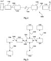
- Fig. 2 shows a schematic representation of a CAN communication system in a wind turbine according to a first embodiment.
- the communication system 1000 has a plurality of CAN nodes 1100, which are each coupled to a CAN distribution unit 1200 via a first communication section 1300.
- the CAN nodes can be coupled to electrical or electronic components 1001 of the wind energy installation 100.
- the respective CAN distribution units 1200 are coupled via a second communication section 1400.
- the first communication section 1300 is a communication section with a short distance and can be configured as an electrical or optical communication section.
- communication between CAN node 1100 and CAN distribution unit 1200 can take place via a first CAN protocol.
- the first CAN protocol can represent the standard CAN protocol according to ISO 11898.
- the data communication can take place in accordance with a second CAN protocol that does not correspond to the standard protocol, but corresponds to a modified standard CAN protocol in order to achieve increased / to be able to use high data transfer rates.
- the communication system transmits data in an electrical transmission using the differential transmission method between the respective participants.
- the half-duplex mode is used, so that the line can only be sent in one direction.
- a transmission takes place via separate transmit (Tx) and receive services (Rx).
- the sender monitors the bus in order to verify transmitted data and to recognize whether another participant with a higher priority is placing a frame on the bus.
- the station wishing to send must hold back its data and accept the data from the other station with the higher-priority frame.
- Each of the CAN nodes as a participant can hold back its data until the bus is free and no participant places a frame with a higher priority on the bus.
- the first communication section can be designed as a CAN bus.
- Fig. 3 shows a schematic representation of a system architecture of a wind energy installation according to the first exemplary embodiment.
- a CAN distribution unit 1201 for a tower of the wind power plant shows a CAN distribution unit 1202 for a nacelle of the wind power plant, a CAN distribution unit 1203 as an optical distributor for the nacelle of the wind power plant and a CAN distribution unit 1204 as an optical distributor for the rotor of the wind power plant .
- Communication takes place between the respective CAN distribution units 1201-1204 via the second communication section 1400 and thus in accordance with a second CAN protocol.
- a control unit 1102 for the tower can be coupled to the CAN distribution unit for the tower 1201 via a first communication section 1300.
- a control unit 1101 for the gondola can be coupled to the CAN distribution unit 1202 for the gondola via a first communication section 1300.
- a rectifier control unit 1103 can be coupled to the CAN distribution unit for the nacelle 1202 via a first communication section 1300.
- all frames sent by the units connected to the CAN communication system are forwarded via one of the CAN distribution units.
- the CAN distribution units are thus responsible for both communication with other CAN distribution units and for communication with the control units connected directly to the respective CAN distribution unit.
- Fig. 4 shows a schematic block diagram of a section of a CAN communication system according to a first embodiment.
- a CAN node 1100 is coupled to a CAN distribution unit 1200 via a first CAN communication section 1300.
- the first communication section 1300 may have a transmission line Tx and a reception line Rx.
- the CAN node 1100 can have a CAN node controller 1110, an electrical transceiver 1140 or an (optical) transmitter 1120 and an (optical) receiver 1130.
- the CAN distribution unit 1200 can be a Interface unit 1210 e.g. B. with an electrical transceiver 1220 or with an (optical) receiver 1240 and an (optical) transmitter 1220.
- the CAN distribution unit 1200 has a switching unit 1230 and an error detection and processing unit 1260.
- the CAN distribution unit 1210 which can serve as an input stage, automatic detection of the baud rate of the connected CAN nodes 1100, decoding of the CAN frames, generation of an acknowledge signal, encoding of the CAN frames and a Receive and transmit buffers with at least one frame length are provided.
- the CAN node 1100 can have a CAN node controller 1110 and either an electrical transceiver 1140 or, alternatively, an optical transmitter 1120 and an optical receiver 1130.
- the CAN node 1100 can thus either have an optical transmission / reception module or an electrical transmission / reception module.
- the optical transmitter 1120 and the optical receiver 1130 communicate with the optical receiver 1240 and the optical transmitter 1220 of the CAN distribution unit 1200.
- the electrical transceiver 1140 of the CAN node 1100 communicates via the electrical lines 1301, 1302 with the electrical transceiver 1220 in the CAN network. Distribution unit 1200.
- the optical receiver 1240 and the optical transmitter 1250 communicate with the interface unit 1210 via an electrical receiving line eRx and an electrical transmitting line eTx.
- the electrical transceiver 1220 communicates with an interface unit 1210 via an electrical receiving line eRx and an electrical transmitting line eTx.
- communication according to the second CAN protocol can take place if a CAN distributor unit is also provided on the opposite side, which enables communication according to the second CAN protocol.
- Fig. 5 shows a schematic block diagram of a CAN distribution unit according to a third embodiment.
- the transmitter and receiver at the input and / or output of the CAN distribution unit 1200 can also be integrated in an interface unit 1210.
- a corresponding interface input unit 1210 can have an edge detector 1211, a frame detector 1212, a transmission buffer 1213, a baud rate generator 1214, an acknowledge generator 1215, a frame encoder 1216 and a transmit buffer 1217.
- the switching unit 1230 can have a priority control unit 1231, a state control unit 1232 and a flow control unit 1233.
- the interface 1210 can have a frame recognition unit 1212, a baud rate recognition unit 1214a, a baud rate generator 1214, an arbitration unit 1218 and a transmission buffer and a transmission control unit 1219.
- a decentralized approach to managing the interfaces is provided.
- the input frames recognized by the frame recognition unit 1212 are copied directly into the transmission buffer 1219.
- the priority of the frames can be determined in the send buffer 1219 and they can be transmitted to the correspondingly connected participants.
- a frame that is subsequently sent is only sent if an acknowledgment signal has been transmitted.
- a buffer in which a complete frame can be recorded is sufficient as an input buffer. Because the received frames are forwarded directly to the transmit buffer, the input unit can work faster.
- An identifier in the frame can be read in the transmission control unit 1219 in order to determine the priority of the frame.
- Fig. 6 shows a block diagram of a construction data and frame detection in a CAN distribution unit according to a second embodiment of the invention.
- Fig. 6 only the clock processing and clock distribution is shown. The flow of data has been largely abstracted.
- An incoming signal is analyzed in the baud rate detection unit 1214a. Based on the analysis result, a new clock is synthesized in the baud rate generator 1214.
- a frame recognition unit 1212 is controlled with the synthesized clock.
- An input frame is fed to the arbitration unit 1218.
- the input frames are recognized in the frame recognition unit 1212.
- the baud rate of the frame is determined in the baud rate detection unit 1214a.
- the baud rate on the second section of the bus ie for example on the optical connection, can be determined in the baud rate detection unit 1214a.
- the baud rate generator 1212 two clocks are generated for scanning the receiving line and the transmitting line. After the baud rate has been recognized and the clock has been generated, the frame recognition unit 1212 can be activated in order to determine the useful data of the frame on the basis of the baud clock.
- the sender can transmit an acknowledgment signal to mark the frame as a valid frame. This information can then be forwarded to the connected participants.
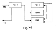
- Fig. 7 shows a schematic block diagram of a frame detection in a CAN distribution unit according to a second embodiment.
- the frame recognition unit 1212 has a stuff bit filter 1212a, a first state machine 1212b and a second state machine 1212c.
- the frames are received via the input line Rx and an acknowledge signal Ack can be transmitted via a transmission line Tx when a frame has been successfully received.
- the frame recognition unit 1212 according to the invention can recognize both frames according to CAN 2.0A and also according to CAN 2.0B.
- the stuff bit filter 1212a is provided for the stuff bits in the data stream. By removing these stuff bits before the frame recognition is started, the frame recognition can be made simpler.
- the frame recognition unit 1212 is also designed to forward the recognized frames to further connections.
- the first state machine 1212b can have a frame error FE, an active frame FA, frame data FD and a valid frame FG as output signal, which are transmitted from the first to the second state machine.
- the output signals frame error FF and frame active FA can be output.
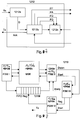
- Fig. 8 shows a schematic block diagram of a transmission unit in a CAN distribution unit according to the third embodiment.
- the state machine FSM I of the transmission unit 1219 receives the frames distributed by the switching unit 1230 and can sort the frames according to their priority. The received frames can be temporarily stored in the buffer 1217b.
- the first-in-first-out memory 1217d is used to manage the frames in the memory 1217b.
- the state machine FSM II 1217c checks which frame has the highest priority and sends that frame with the highest priority to the output state machine FSM III 1216a.
- the state machine FSM IV monitors the transmission process and deletes the frame from the buffer 1217d if it is successful. Otherwise, the sending process can be repeated.
- the state machine 1219a receives the data from the frame recognition unit 1212 and can temporarily store the data in the buffer 1219b.
- Another state machine 1219c determines the priority of the frames stored in the buffer 1219b and reads out the frames with the highest priority from the buffer 1219b.
- the state machine 1219d is responsible for sending the frame extracted from the buffer.
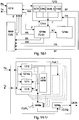
- Fig. 9 shows a block diagram of an error detection unit in a CAN distribution unit according to the fourth embodiment.
- the arbitration unit 1218 receives frames from the receive line Rx. These data are forwarded to the frame recognition unit 1212, which transmits an acknowledge signal Ack back to the arbitration unit 1218.
- the frames are recognized in the frame recognition unit 1212 and if an error F is present, this is transmitted to an error unit 1218a.
- the error unit 1218a then transmits a no acknowledge signal kAcK to the frame recognition unit 1212, which prevents an acknowledge signal Ack from being sent.
- the error unit 1218a then transmits the information “no subscriber” kT to the baud rate recognition, which transmits a port shutdown signal PA to the frame recognition unit 1212 and to the transmission unit 1219 as the output signal.
- the error unit 1218k also transmits a transmission stop SS signal or a transmission repeat signal SW.
- Possible errors include bit errors, stuff bit errors, CRC errors, form errors or acknowledgment errors.
- a bit error that occurs during the arbitration is recognized in the arbitration unit 1218 and this information is forwarded to the error unit 1218a. As a result, the error unit 1218a cancels a transmission process. If frames are currently being received, then the error unit 1218a ensures that no acknowledge signal kAck is sent back. If errors occur in the CRD sums, then this can be forwarded by the frame recognition unit 1212 to the error unit 1218.
- Fig. 10 shows a block diagram of part of a CAN distribution unit according to a fifth embodiment.
- a frame recognition unit 1212 a baud rate recognition unit 1214a, a baud rate generator 1214, an arbitration unit 1218 and a transmission control unit 1219 are provided.
- an error unit 1218a and an LED control unit 1218b can be provided.
Landscapes
- Engineering & Computer Science (AREA)
- Computer Networks & Wireless Communication (AREA)
- Signal Processing (AREA)
- Small-Scale Networks (AREA)
- Cable Transmission Systems, Equalization Of Radio And Reduction Of Echo (AREA)
- Wind Motors (AREA)
- Arrangements For Transmission Of Measured Signals (AREA)
- Selective Calling Equipment (AREA)
- Communication Control (AREA)
Claims (5)
- Eolienne, avec
au moins un premier composant (1001) électrique et/ou électronique,
au moins un deuxième composant (1001) électrique et/ou électronique,
un système de communication CAN (Controller Area Network) (1000) pour la communication entre l'au moins un premier et l'au moins un deuxième composant (1001) électrique et/ou électronique,
dans lequel le système de communication CAN (Controller Area Network) (1000) présente au moins un premier et un deuxième nœud CAN (1100), au moins une première et une deuxième unité de répartition CAN (1200), au moins une première section de communication (1300) pour la communication entre l'au moins un premier ou deuxième nœud CAN (1100) et l'au moins une première ou deuxième unité de répartition CAN (1200), et au moins une deuxième section de communication (1400) pour la communication entre l'au moins une première et deuxième unité de répartition CAN (1200),
dans lequel l'au moins une première unité de répartition CAN (1200) est couplée au premier nœud CAN (1100) par l'intermédiaire de la première section de communication (1300) et à la deuxième unité de répartition CAN (1200) par l'intermédiaire de la deuxième section de communication (1400),
dans lequel la deuxième unité de répartition CAN (1200) est couplée au deuxième nœud CAN (1100) par l'intermédiaire de la première section de communication (1300),
dans lequel le premier composant (1001) électrique et/ou électronique est couplé au premier nœud CAN (1100) et dans lequel le deuxième composant (1001) électrique et/ou électronique est couplé au deuxième nœud CAN (1100) pour permettre une communication entre le premier et le deuxième composant (1001) électrique et/ou électronique,
dans lequel l'au moins une première et deuxième unité de répartition CAN (1200) sont configurées pour mettre en œuvre par l'intermédiaire de l'au moins une première section de communication (1300) une communication de données avec l'au moins un premier ou l'au moins un deuxième nœud CAN (1100) sur la base d'un premier protocole CAN, lequel constitue un protocole CAN standard selon la norme ISO 11898,
dans lequel l'au moins une première et deuxième unité de répartition CAN (1200) sont configurées pour mettre en œuvre entre elles par l'intermédiaire de l'au moins une deuxième section de communication (1400) une communication de données sur la base d'un deuxième protocole CAN, lequel diffère du protocole CAN standard,
dans lequel l'au moins une deuxième section de communication (1400) est configurée en tant que câble optique,
dans lequel l'au moins une première et l'au moins une deuxième section de communication (1200, 1400) sont configurées respectivement en tant qu'une connexion directe point à point. - Eolienne selon la revendication 1,
dans laquelle la longueur de l'au moins une deuxième section de communication (1400) est sensiblement plus grande que la longueur de l'au moins une première section de communication (1300). - Eolienne selon l'une quelconque des revendications 1 à 2, dans laquelle
au moins une première et une deuxième unité de répartition CAN (1200) présentent respectivement une interface CAN (1210) pour la communication avec l'au moins un premier ou deuxième nœud CAN (1100). - Eolienne selon la revendication 3, dans laquelle
les interfaces CAN (1210) présentent respectivement une unité de reconnaissance de trame (1212), une unité de reconnaissance de débits en bauds (1214a), un générateur de débits en bauds (1214) et une unité d'arbitrage (1218). - Procédé de communication entre au moins un premier composant (1001) électrique et/ou électronique et au moins un deuxième composant (1001) électrique et/ou électronique d'une éolienne par l'intermédiaire d'un système de communication CAN (Controller Area Network) (1000),
dans lequel le système de communication CAN (Controller Area Network) (1000) présente au moins un premier et un deuxième nœud CAN (1100), au moins une première et une deuxième unité de répartition CAN (1200), au moins une première section de communication (1300) pour la communication entre l'au moins un premier ou deuxième nœud CAN (1100) et l'au moins une première ou deuxième unité de répartition CAN (1200), et au moins une deuxième section de communication (1400) pour la communication entre l'au moins une première et deuxième unité de répartition CAN (1200), avec les étapes de :couplage de la première unité de répartition CAN (1200) au premier nœud CAN (1100) par l'intermédiaire de la première section de communication (1300), etcouplage de la première unité de répartition (1200) à la deuxième unité de répartition CAN (1200) par l'intermédiaire d'une deuxième section de communication (1400),couplage de la deuxième unité de répartition CAN (1200) au deuxième nœud CAN (1100) par l'intermédiaire de la première section de communication (1300),couplage du premier composant (1001) électrique et/ou électronique au premier nœud CAN (1100),couplage du deuxième composant (1001) électrique et/ou électronique au deuxième nœud CAN (1100) pour permettre une communication entre le premier et le deuxième composant (1001) électrique et/ou électronique,communication de la première unité de répartition CAN (1200) avec le premier nœud CAN (1100) par l'intermédiaire de la première section de communication (1300),communication de la première unité de répartition CAN (1200) avec la deuxième unité de répartition CAN (1200) par l'intermédiaire de la deuxième section de communication (1400),communication de la deuxième unité de répartition CAN (1200) avec le deuxième nœud CAN (1100) par l'intermédiaire de la première section de communication (1300),dans lequel la communication de données par l'intermédiaire de la première section de communication (1300) a lieu sur la base d'un premier protocole CAN, lequel correspond au protocole standard CAN, etdans lequel la communication de données par l'intermédiaire de la deuxième section de communication (1400) a lieu sur un deuxième protocole CAN, lequel est différent du protocole CAN standard,dans lequel au moins la deuxième section de communication (1400) est configurée en tant que câble optique,dans lequel la première et la deuxième section de communication (1200, 1400) sont configurées respectivement en tant qu'une connexion directe point à point.
Applications Claiming Priority (2)
| Application Number | Priority Date | Filing Date | Title |
|---|---|---|---|
| DE102015201019.8A DE102015201019A1 (de) | 2015-01-22 | 2015-01-22 | Windenergieanlage und Windenergieanlagen-Bussystem |
| PCT/EP2016/051212 WO2016116553A1 (fr) | 2015-01-22 | 2016-01-21 | Éolienne, système de communication d'une éolienne et procédé permettant de faire fonctionner un système de bus |
Publications (2)
| Publication Number | Publication Date |
|---|---|
| EP3248336A1 EP3248336A1 (fr) | 2017-11-29 |
| EP3248336B1 true EP3248336B1 (fr) | 2021-01-06 |
Family
ID=55273218
Family Applications (1)
| Application Number | Title | Priority Date | Filing Date |
|---|---|---|---|
| EP16702352.2A Active EP3248336B1 (fr) | 2015-01-22 | 2016-01-21 | Éolienne et procédé de communication |
Country Status (13)
| Country | Link |
|---|---|
| US (1) | US20180006841A1 (fr) |
| EP (1) | EP3248336B1 (fr) |
| JP (1) | JP6527232B2 (fr) |
| KR (1) | KR20170105084A (fr) |
| CN (1) | CN107210944A (fr) |
| AR (1) | AR103487A1 (fr) |
| BR (1) | BR112017015733A2 (fr) |
| CA (1) | CA2972145A1 (fr) |
| DE (1) | DE102015201019A1 (fr) |
| DK (1) | DK3248336T3 (fr) |
| TW (1) | TW201644235A (fr) |
| UY (1) | UY36534A (fr) |
| WO (1) | WO2016116553A1 (fr) |
Citations (9)
| Publication number | Priority date | Publication date | Assignee | Title |
|---|---|---|---|---|
| EP0792048A1 (fr) * | 1996-02-20 | 1997-08-27 | Commissariat A L'energie Atomique | Pont-routeur multiprotocoles pour réseaux industriels |
| US20030151259A1 (en) * | 2002-02-11 | 2003-08-14 | Lorenz Feddersen | Variable speed wind turbine having a passive grid side rectifier with scalar power control and dependent pitch control |
| US6654355B1 (en) * | 1999-12-14 | 2003-11-25 | Schneider Automation Inc. | Bridge for CAN to TCP/IP connection |
| US20080107029A1 (en) * | 2006-11-08 | 2008-05-08 | Honeywell International Inc. | Embedded self-checking asynchronous pipelined enforcement (escape) |
| US20110049887A1 (en) * | 2009-08-28 | 2011-03-03 | Vestas Wind Systems A/S | Wind turbine data acquisition system |
| US20110150497A1 (en) * | 2009-12-21 | 2011-06-23 | General Electric Company | Contactless infrared data transmission for wind turbines |
| JP2011135521A (ja) * | 2009-12-25 | 2011-07-07 | Autonetworks Technologies Ltd | 光通信装置、通信ハーネス及び通信システム |
| US20140054892A1 (en) * | 2012-08-27 | 2014-02-27 | General Electric Company | Wind turbine pitch control system |
| WO2015079176A1 (fr) * | 2013-11-27 | 2015-06-04 | Université de Picardie Jules Verne | Transmission sans fil entre une partie mobile et une partie fixe dans une nacelle d'eolienne. |
Family Cites Families (10)
| Publication number | Priority date | Publication date | Assignee | Title |
|---|---|---|---|---|
| GB2351884B (en) * | 1999-04-10 | 2002-07-31 | Peter Strong | Data transmission method |
| JP2001156364A (ja) * | 1999-11-29 | 2001-06-08 | Sumitomo Electric Ind Ltd | 広帯域光増幅器 |
| DE10100343B4 (de) * | 2001-01-05 | 2013-05-08 | Infineon Technologies Ag | Bus-System |
| DE102007011835A1 (de) * | 2007-03-12 | 2008-10-02 | µ-SEN GMBH | Sensormodul und Sensornetzwerk zur Überwachung einer Windenergieanlage sowie entsprechende Überwachungsverfahren |
| CN102619682B (zh) * | 2011-01-30 | 2014-05-14 | 华锐风电科技(集团)股份有限公司 | 用于风力发电机组的变桨控制系统 |
| EP2521319B1 (fr) * | 2011-05-02 | 2015-10-14 | Robert Bosch GmbH | Réseau de type CAN avec taux de débit de données flexible |
| US9037631B2 (en) * | 2012-02-22 | 2015-05-19 | Ether-2 Corp. | Network communications |
| DE102012215765A1 (de) * | 2012-09-05 | 2014-05-15 | Robert Bosch Gmbh | Gateway-Modul für ein Kommunikationssystem, Kommunikationssystem und Verfahren zur Übertragung von Daten zwischen Teilnehmern eines Kommunikationssystems |
| CN203704983U (zh) * | 2014-03-08 | 2014-07-09 | 湖南科技大学 | 一种基于无线传输的风力机叶根应力和叶片振动检测装置 |
| CN104092515B (zh) * | 2014-07-11 | 2017-03-22 | 电子科技大学 | 兼容can2.0b协议的can总线通信方法 |
-
2015
- 2015-01-22 DE DE102015201019.8A patent/DE102015201019A1/de not_active Withdrawn
-
2016
- 2016-01-21 JP JP2017535795A patent/JP6527232B2/ja not_active Expired - Fee Related
- 2016-01-21 BR BR112017015733A patent/BR112017015733A2/pt not_active Application Discontinuation
- 2016-01-21 KR KR1020177022808A patent/KR20170105084A/ko not_active Ceased
- 2016-01-21 US US15/543,117 patent/US20180006841A1/en not_active Abandoned
- 2016-01-21 CA CA2972145A patent/CA2972145A1/fr not_active Abandoned
- 2016-01-21 WO PCT/EP2016/051212 patent/WO2016116553A1/fr not_active Ceased
- 2016-01-21 CN CN201680006994.5A patent/CN107210944A/zh active Pending
- 2016-01-21 DK DK16702352.2T patent/DK3248336T3/da active
- 2016-01-21 EP EP16702352.2A patent/EP3248336B1/fr active Active
- 2016-01-22 AR ARP160100177A patent/AR103487A1/es unknown
- 2016-01-22 TW TW105102130A patent/TW201644235A/zh unknown
- 2016-01-22 UY UY0001036534A patent/UY36534A/es not_active Application Discontinuation
Patent Citations (11)
| Publication number | Priority date | Publication date | Assignee | Title |
|---|---|---|---|---|
| EP0792048A1 (fr) * | 1996-02-20 | 1997-08-27 | Commissariat A L'energie Atomique | Pont-routeur multiprotocoles pour réseaux industriels |
| JPH09233114A (ja) * | 1996-02-20 | 1997-09-05 | Commiss Energ Atom | 産業用のネットワークに対するマルチプロトコルルーターブリッジと二つの離れた遠隔局に分配されたメディア間のマルチプロトコル通信システム |
| US6654355B1 (en) * | 1999-12-14 | 2003-11-25 | Schneider Automation Inc. | Bridge for CAN to TCP/IP connection |
| US20030151259A1 (en) * | 2002-02-11 | 2003-08-14 | Lorenz Feddersen | Variable speed wind turbine having a passive grid side rectifier with scalar power control and dependent pitch control |
| US20080107029A1 (en) * | 2006-11-08 | 2008-05-08 | Honeywell International Inc. | Embedded self-checking asynchronous pipelined enforcement (escape) |
| US20110049887A1 (en) * | 2009-08-28 | 2011-03-03 | Vestas Wind Systems A/S | Wind turbine data acquisition system |
| US20110150497A1 (en) * | 2009-12-21 | 2011-06-23 | General Electric Company | Contactless infrared data transmission for wind turbines |
| JP2011135521A (ja) * | 2009-12-25 | 2011-07-07 | Autonetworks Technologies Ltd | 光通信装置、通信ハーネス及び通信システム |
| US20140054892A1 (en) * | 2012-08-27 | 2014-02-27 | General Electric Company | Wind turbine pitch control system |
| WO2015079176A1 (fr) * | 2013-11-27 | 2015-06-04 | Université de Picardie Jules Verne | Transmission sans fil entre une partie mobile et une partie fixe dans une nacelle d'eolienne. |
| US20160377059A1 (en) * | 2013-11-27 | 2016-12-29 | Université de Picardie Jules Verne | Wireless transmission between a movable portion and a stationary portion in a windmill nacelle |
Also Published As
| Publication number | Publication date |
|---|---|
| WO2016116553A1 (fr) | 2016-07-28 |
| CA2972145A1 (fr) | 2016-07-28 |
| TW201644235A (zh) | 2016-12-16 |
| CN107210944A (zh) | 2017-09-26 |
| US20180006841A1 (en) | 2018-01-04 |
| DK3248336T3 (da) | 2021-01-25 |
| UY36534A (es) | 2016-08-31 |
| DE102015201019A1 (de) | 2016-07-28 |
| JP2018504840A (ja) | 2018-02-15 |
| JP6527232B2 (ja) | 2019-06-05 |
| AR103487A1 (es) | 2017-05-10 |
| EP3248336A1 (fr) | 2017-11-29 |
| BR112017015733A2 (pt) | 2018-03-13 |
| KR20170105084A (ko) | 2017-09-18 |
Similar Documents
| Publication | Publication Date | Title |
|---|---|---|
| DE69026331T2 (de) | Station zu Station Vollduplexkommunikation bei Kommunikationsnetzwerken | |
| DE102005021820B4 (de) | Kommunikationsmitteilungs-Konvertierungseinrichtung, Kommunikationsverfahren und Kommunikationssystem | |
| DE69633894T2 (de) | Modem zur Kommunikation von Hochgeschwindigkeitsdaten | |
| EP1554839B1 (fr) | Procede et noeud pour utiliser en parallele un reseau de communication pour des applications temps reel et des applications non temps reel | |
| DE2953444C2 (de) | Anordnung und Verfahren für ein digitales Datenübertragungsnetzwerk | |
| DE69635834T2 (de) | Hochgeschwindigkeitsdatennetz- System und Verfahren | |
| EP2619947B1 (fr) | Procédé et dispositif de transmission de données série avec débit de données variable | |
| EP2137893B1 (fr) | Dispositif de commutation de paquets et réseau de communication local comprenant un tel dispositif de commutation de paquets | |
| EP2538619A1 (fr) | Procédé destiné à la transmission de paquets de données | |
| DE102017125086A1 (de) | Datenübertragungsverfahren und Kommunikationsnetzwerk | |
| WO2004071025A1 (fr) | Coupleur pour reseau a topologie en anneau et reseau ethernet | |
| EP3531629A1 (fr) | Poste d'abonné pour un système de bus et procédé permettant d'améliorer le débit de données d'un système de bus | |
| DE10296700T5 (de) | Flusssteuerungssystem zur Verringerung der Speicherpufferanforderungen und zur Herstellung einer Prioritätsbedienung zwischen Netzen | |
| EP1884851B1 (fr) | Procédé, noeud et réseau destinés à l'envoi cyclique de télégrammes par Ethernet | |
| EP3248336B1 (fr) | Éolienne et procédé de communication | |
| DE102014210505A1 (de) | Übertragungseinheit mit Prüffunktion | |
| DE102020205268A1 (de) | Kommunikationssteuereinrichtung und Sende-/Empfangseinrichtung für eine Teilnehmerstation eines seriellen Bussystems und Verfahren zur Kommunikation in einem seriellen Bussystem | |
| DE102019213322A1 (de) | Ethernet Physical Layer Transceiver für Zweidraht-Bustopologie | |
| EP1690390B1 (fr) | Procede de transmission de donnees via un bus de donnees, et systeme et passerelle permettant la mise en oeuvre dudit procede | |
| DE10037969C2 (de) | Verfahren zur Erkennung einer flexiblen Vernetzung von Baugruppen bei beliebiger Netztopologie sowie zum Informationsaustausch zwischen solchen Baugruppen | |
| DE69300379T2 (de) | Vorrichtung zum Anschluss eines Terminals an einen Übertragungskanal. | |
| DE102012201669B4 (de) | Verfahren und Kommunikationscontroller zur Datenübertragung zwischen zwei mittels Übertragungsstrecken verbundenen Datenverarbeitungseinheiten | |
| EP1115228B1 (fr) | Dispositif de couplage pour un réseau de données | |
| DE102004062034A1 (de) | Repeaterknoten für ein Netzwerk | |
| EP1593235A1 (fr) | Systeme de communication deterministe |
Legal Events
| Date | Code | Title | Description |
|---|---|---|---|
| STAA | Information on the status of an ep patent application or granted ep patent |
Free format text: STATUS: THE INTERNATIONAL PUBLICATION HAS BEEN MADE |
|
| PUAI | Public reference made under article 153(3) epc to a published international application that has entered the european phase |
Free format text: ORIGINAL CODE: 0009012 |
|
| STAA | Information on the status of an ep patent application or granted ep patent |
Free format text: STATUS: REQUEST FOR EXAMINATION WAS MADE |
|
| 17P | Request for examination filed |
Effective date: 20170822 |
|
| AK | Designated contracting states |
Kind code of ref document: A1 Designated state(s): AL AT BE BG CH CY CZ DE DK EE ES FI FR GB GR HR HU IE IS IT LI LT LU LV MC MK MT NL NO PL PT RO RS SE SI SK SM TR |
|
| AX | Request for extension of the european patent |
Extension state: BA ME |
|
| DAV | Request for validation of the european patent (deleted) | ||
| DAX | Request for extension of the european patent (deleted) | ||
| STAA | Information on the status of an ep patent application or granted ep patent |
Free format text: STATUS: EXAMINATION IS IN PROGRESS |
|
| 17Q | First examination report despatched |
Effective date: 20180921 |
|
| GRAP | Despatch of communication of intention to grant a patent |
Free format text: ORIGINAL CODE: EPIDOSNIGR1 |
|
| STAA | Information on the status of an ep patent application or granted ep patent |
Free format text: STATUS: GRANT OF PATENT IS INTENDED |
|
| INTG | Intention to grant announced |
Effective date: 20201002 |
|
| GRAS | Grant fee paid |
Free format text: ORIGINAL CODE: EPIDOSNIGR3 |
|
| GRAA | (expected) grant |
Free format text: ORIGINAL CODE: 0009210 |
|
| STAA | Information on the status of an ep patent application or granted ep patent |
Free format text: STATUS: THE PATENT HAS BEEN GRANTED |
|
| AK | Designated contracting states |
Kind code of ref document: B1 Designated state(s): AL AT BE BG CH CY CZ DE DK EE ES FI FR GB GR HR HU IE IS IT LI LT LU LV MC MK MT NL NO PL PT RO RS SE SI SK SM TR |
|
| REG | Reference to a national code |
Ref country code: GB Ref legal event code: FG4D Free format text: NOT ENGLISH |
|
| REG | Reference to a national code |
Ref country code: AT Ref legal event code: REF Ref document number: 1353550 Country of ref document: AT Kind code of ref document: T Effective date: 20210115 Ref country code: CH Ref legal event code: EP |
|
| REG | Reference to a national code |
Ref country code: DK Ref legal event code: T3 Effective date: 20210119 |
|
| REG | Reference to a national code |
Ref country code: DE Ref legal event code: R096 Ref document number: 502016012123 Country of ref document: DE |
|
| REG | Reference to a national code |
Ref country code: IE Ref legal event code: FG4D Free format text: LANGUAGE OF EP DOCUMENT: GERMAN |
|
| REG | Reference to a national code |
Ref country code: NL Ref legal event code: FP |
|
| REG | Reference to a national code |
Ref country code: LT Ref legal event code: MG9D |
|
| PG25 | Lapsed in a contracting state [announced via postgrant information from national office to epo] |
Ref country code: GR Free format text: LAPSE BECAUSE OF FAILURE TO SUBMIT A TRANSLATION OF THE DESCRIPTION OR TO PAY THE FEE WITHIN THE PRESCRIBED TIME-LIMIT Effective date: 20210407 Ref country code: HR Free format text: LAPSE BECAUSE OF FAILURE TO SUBMIT A TRANSLATION OF THE DESCRIPTION OR TO PAY THE FEE WITHIN THE PRESCRIBED TIME-LIMIT Effective date: 20210106 Ref country code: FI Free format text: LAPSE BECAUSE OF FAILURE TO SUBMIT A TRANSLATION OF THE DESCRIPTION OR TO PAY THE FEE WITHIN THE PRESCRIBED TIME-LIMIT Effective date: 20210106 Ref country code: PT Free format text: LAPSE BECAUSE OF FAILURE TO SUBMIT A TRANSLATION OF THE DESCRIPTION OR TO PAY THE FEE WITHIN THE PRESCRIBED TIME-LIMIT Effective date: 20210506 Ref country code: NO Free format text: LAPSE BECAUSE OF FAILURE TO SUBMIT A TRANSLATION OF THE DESCRIPTION OR TO PAY THE FEE WITHIN THE PRESCRIBED TIME-LIMIT Effective date: 20210406 Ref country code: BG Free format text: LAPSE BECAUSE OF FAILURE TO SUBMIT A TRANSLATION OF THE DESCRIPTION OR TO PAY THE FEE WITHIN THE PRESCRIBED TIME-LIMIT Effective date: 20210406 Ref country code: LT Free format text: LAPSE BECAUSE OF FAILURE TO SUBMIT A TRANSLATION OF THE DESCRIPTION OR TO PAY THE FEE WITHIN THE PRESCRIBED TIME-LIMIT Effective date: 20210106 |
|
| PG25 | Lapsed in a contracting state [announced via postgrant information from national office to epo] |
Ref country code: SE Free format text: LAPSE BECAUSE OF FAILURE TO SUBMIT A TRANSLATION OF THE DESCRIPTION OR TO PAY THE FEE WITHIN THE PRESCRIBED TIME-LIMIT Effective date: 20210106 Ref country code: LV Free format text: LAPSE BECAUSE OF FAILURE TO SUBMIT A TRANSLATION OF THE DESCRIPTION OR TO PAY THE FEE WITHIN THE PRESCRIBED TIME-LIMIT Effective date: 20210106 Ref country code: PL Free format text: LAPSE BECAUSE OF FAILURE TO SUBMIT A TRANSLATION OF THE DESCRIPTION OR TO PAY THE FEE WITHIN THE PRESCRIBED TIME-LIMIT Effective date: 20210106 Ref country code: RS Free format text: LAPSE BECAUSE OF FAILURE TO SUBMIT A TRANSLATION OF THE DESCRIPTION OR TO PAY THE FEE WITHIN THE PRESCRIBED TIME-LIMIT Effective date: 20210106 |
|
| REG | Reference to a national code |
Ref country code: CH Ref legal event code: PL |
|
| PG25 | Lapsed in a contracting state [announced via postgrant information from national office to epo] |
Ref country code: LU Free format text: LAPSE BECAUSE OF NON-PAYMENT OF DUE FEES Effective date: 20210121 Ref country code: IS Free format text: LAPSE BECAUSE OF FAILURE TO SUBMIT A TRANSLATION OF THE DESCRIPTION OR TO PAY THE FEE WITHIN THE PRESCRIBED TIME-LIMIT Effective date: 20210506 |
|
| REG | Reference to a national code |
Ref country code: BE Ref legal event code: MM Effective date: 20210131 |
|
| REG | Reference to a national code |
Ref country code: DE Ref legal event code: R097 Ref document number: 502016012123 Country of ref document: DE |
|
| PG25 | Lapsed in a contracting state [announced via postgrant information from national office to epo] |
Ref country code: SM Free format text: LAPSE BECAUSE OF FAILURE TO SUBMIT A TRANSLATION OF THE DESCRIPTION OR TO PAY THE FEE WITHIN THE PRESCRIBED TIME-LIMIT Effective date: 20210106 Ref country code: MC Free format text: LAPSE BECAUSE OF FAILURE TO SUBMIT A TRANSLATION OF THE DESCRIPTION OR TO PAY THE FEE WITHIN THE PRESCRIBED TIME-LIMIT Effective date: 20210106 Ref country code: EE Free format text: LAPSE BECAUSE OF FAILURE TO SUBMIT A TRANSLATION OF THE DESCRIPTION OR TO PAY THE FEE WITHIN THE PRESCRIBED TIME-LIMIT Effective date: 20210106 Ref country code: CZ Free format text: LAPSE BECAUSE OF FAILURE TO SUBMIT A TRANSLATION OF THE DESCRIPTION OR TO PAY THE FEE WITHIN THE PRESCRIBED TIME-LIMIT Effective date: 20210106 |
|
| PLBE | No opposition filed within time limit |
Free format text: ORIGINAL CODE: 0009261 |
|
| STAA | Information on the status of an ep patent application or granted ep patent |
Free format text: STATUS: NO OPPOSITION FILED WITHIN TIME LIMIT |
|
| PG25 | Lapsed in a contracting state [announced via postgrant information from national office to epo] |
Ref country code: LI Free format text: LAPSE BECAUSE OF NON-PAYMENT OF DUE FEES Effective date: 20210131 Ref country code: SK Free format text: LAPSE BECAUSE OF FAILURE TO SUBMIT A TRANSLATION OF THE DESCRIPTION OR TO PAY THE FEE WITHIN THE PRESCRIBED TIME-LIMIT Effective date: 20210106 Ref country code: RO Free format text: LAPSE BECAUSE OF FAILURE TO SUBMIT A TRANSLATION OF THE DESCRIPTION OR TO PAY THE FEE WITHIN THE PRESCRIBED TIME-LIMIT Effective date: 20210106 Ref country code: CH Free format text: LAPSE BECAUSE OF NON-PAYMENT OF DUE FEES Effective date: 20210131 |
|
| 26N | No opposition filed |
Effective date: 20211007 |
|
| PG25 | Lapsed in a contracting state [announced via postgrant information from national office to epo] |
Ref country code: AL Free format text: LAPSE BECAUSE OF FAILURE TO SUBMIT A TRANSLATION OF THE DESCRIPTION OR TO PAY THE FEE WITHIN THE PRESCRIBED TIME-LIMIT Effective date: 20210106 Ref country code: ES Free format text: LAPSE BECAUSE OF FAILURE TO SUBMIT A TRANSLATION OF THE DESCRIPTION OR TO PAY THE FEE WITHIN THE PRESCRIBED TIME-LIMIT Effective date: 20210106 Ref country code: IE Free format text: LAPSE BECAUSE OF NON-PAYMENT OF DUE FEES Effective date: 20210121 |
|
| PG25 | Lapsed in a contracting state [announced via postgrant information from national office to epo] |
Ref country code: SI Free format text: LAPSE BECAUSE OF FAILURE TO SUBMIT A TRANSLATION OF THE DESCRIPTION OR TO PAY THE FEE WITHIN THE PRESCRIBED TIME-LIMIT Effective date: 20210106 |
|
| REG | Reference to a national code |
Ref country code: AT Ref legal event code: MM01 Ref document number: 1353550 Country of ref document: AT Kind code of ref document: T Effective date: 20210121 |
|
| PG25 | Lapsed in a contracting state [announced via postgrant information from national office to epo] |
Ref country code: IT Free format text: LAPSE BECAUSE OF FAILURE TO SUBMIT A TRANSLATION OF THE DESCRIPTION OR TO PAY THE FEE WITHIN THE PRESCRIBED TIME-LIMIT Effective date: 20210106 Ref country code: AT Free format text: LAPSE BECAUSE OF NON-PAYMENT OF DUE FEES Effective date: 20210121 |
|
| PG25 | Lapsed in a contracting state [announced via postgrant information from national office to epo] |
Ref country code: IS Free format text: LAPSE BECAUSE OF FAILURE TO SUBMIT A TRANSLATION OF THE DESCRIPTION OR TO PAY THE FEE WITHIN THE PRESCRIBED TIME-LIMIT Effective date: 20210506 |
|
| PG25 | Lapsed in a contracting state [announced via postgrant information from national office to epo] |
Ref country code: BE Free format text: LAPSE BECAUSE OF NON-PAYMENT OF DUE FEES Effective date: 20210131 |
|
| PG25 | Lapsed in a contracting state [announced via postgrant information from national office to epo] |
Ref country code: HU Free format text: LAPSE BECAUSE OF FAILURE TO SUBMIT A TRANSLATION OF THE DESCRIPTION OR TO PAY THE FEE WITHIN THE PRESCRIBED TIME-LIMIT; INVALID AB INITIO Effective date: 20160121 |
|
| PG25 | Lapsed in a contracting state [announced via postgrant information from national office to epo] |
Ref country code: CY Free format text: LAPSE BECAUSE OF FAILURE TO SUBMIT A TRANSLATION OF THE DESCRIPTION OR TO PAY THE FEE WITHIN THE PRESCRIBED TIME-LIMIT Effective date: 20210106 |
|
| PG25 | Lapsed in a contracting state [announced via postgrant information from national office to epo] |
Ref country code: MK Free format text: LAPSE BECAUSE OF FAILURE TO SUBMIT A TRANSLATION OF THE DESCRIPTION OR TO PAY THE FEE WITHIN THE PRESCRIBED TIME-LIMIT Effective date: 20210106 |
|
| PG25 | Lapsed in a contracting state [announced via postgrant information from national office to epo] |
Ref country code: MT Free format text: LAPSE BECAUSE OF FAILURE TO SUBMIT A TRANSLATION OF THE DESCRIPTION OR TO PAY THE FEE WITHIN THE PRESCRIBED TIME-LIMIT Effective date: 20210106 |
|
| PG25 | Lapsed in a contracting state [announced via postgrant information from national office to epo] |
Ref country code: TR Free format text: LAPSE BECAUSE OF FAILURE TO SUBMIT A TRANSLATION OF THE DESCRIPTION OR TO PAY THE FEE WITHIN THE PRESCRIBED TIME-LIMIT Effective date: 20210106 |
|
| PGFP | Annual fee paid to national office [announced via postgrant information from national office to epo] |
Ref country code: NL Payment date: 20260121 Year of fee payment: 11 |
|
| PGFP | Annual fee paid to national office [announced via postgrant information from national office to epo] |
Ref country code: GB Payment date: 20260122 Year of fee payment: 11 |
|
| PGFP | Annual fee paid to national office [announced via postgrant information from national office to epo] |
Ref country code: DK Payment date: 20260121 Year of fee payment: 11 Ref country code: DE Payment date: 20260204 Year of fee payment: 11 |
|
| PGFP | Annual fee paid to national office [announced via postgrant information from national office to epo] |
Ref country code: FR Payment date: 20260121 Year of fee payment: 11 |