EP3248491A1 - Klappsystem und ausstattung, die ein solches klappsystem umfasst - Google Patents
Klappsystem und ausstattung, die ein solches klappsystem umfasst Download PDFInfo
- Publication number
- EP3248491A1 EP3248491A1 EP17172651.6A EP17172651A EP3248491A1 EP 3248491 A1 EP3248491 A1 EP 3248491A1 EP 17172651 A EP17172651 A EP 17172651A EP 3248491 A1 EP3248491 A1 EP 3248491A1
- Authority
- EP
- European Patent Office
- Prior art keywords
- tube
- gas reservoir
- airbag
- gas
- tubular sections
- Prior art date
- Legal status (The legal status is an assumption and is not a legal conclusion. Google has not performed a legal analysis and makes no representation as to the accuracy of the status listed.)
- Granted
Links
Images


Classifications
-
- A—HUMAN NECESSITIES
- A41—WEARING APPAREL
- A41D—OUTERWEAR; PROTECTIVE GARMENTS; ACCESSORIES
- A41D13/00—Professional, industrial or sporting protective garments, e.g. surgeons' gowns or garments protecting against blows or punches
- A41D13/015—Professional, industrial or sporting protective garments, e.g. surgeons' gowns or garments protecting against blows or punches with shock-absorbing means
- A41D13/018—Professional, industrial or sporting protective garments, e.g. surgeons' gowns or garments protecting against blows or punches with shock-absorbing means inflatable automatically
Definitions
- the invention relates to a deployable system and equipment comprising such a deployable system.
- the invention applies for example to an inflatable structure such as a tent whose armature is constituted by one or more airbags.
- the invention also applies for example to protective equipment for protecting a body part of a user in a risk situation such as an accident, a fall or any other type of shock.
- the support of the protective equipment is then adapted to be worn by the user for example in the context of a sporting, recreational, professional or domestic activity.
- Protective equipment may also be intended to protect an article in a risk situation such as a fall or other type of impact.
- the deployable system of the Protective equipment is an active protection system in which the actuating device is adapted to detect a risk situation. The protection system is then in the inactive state when no risk situation is detected by the actuating device, and in the active state when a risk situation is detected by the actuating device.
- the gas reservoir is in the conventional form of a cylindrical cartridge.
- Such deployable systems can not be adapted to various applications.
- it is necessary to limit the risk that the gas tank does not hurt the user or damage the support its provision on the equipment must be chosen accurately.
- the invention aims to overcome the problems mentioned above.
- the tube of the gas tank according to the invention which contains the gas before the actuation of the deployable system, can be shaped in any appropriate manner to increase the capacity without risk of compromising the safety of the user or the integrity of the support on which it is mounted.
- the protection system can thus be easily adapted to a large number of new applications.
- the tube of the gas reservoir may consist of a plurality of adjacent tubular sections along the central axis, the plurality of tubular sections comprising said at least one curved tubular section.
- the plurality of tubular sections may comprise at least one straight tubular section along which the central axis is rectilinear.
- the plurality of tubular sections may comprise a plurality of straight tubular sections parallel to each other, and a plurality of bent tubular sections each connecting one of the straight tubular sections to another of the straight tubular sections.
- At least two tubular sections may have dimensions measured transversely to the central axis different.
- the plurality of tubular sections may comprise at least one flexible tubular section forming a curved tubular section.
- the central axis of the curved tubular section may have at least two curvatures extending in at least two secant planes.
- the curvature may have a variable radius of curvature.
- the tube may have at least two discharge ports.
- the protection system may then comprise at least two separate airbags and the discharge ports may be oriented in different directions, each of the discharge ports being connected to one of the airbags, the system actuator protection device in the active state putting in fluid communication at least one of the exhaust ports of the gas tank tube with the inner chamber of the airbag with which said discharge port is connected.
- the tube may have at least one opening provided with a filling valve adapted to be connected to a gas supply source.
- the gas reservoir may comprise a plurality of tubes and a manifold into which the outlets of the tubes open.
- the deployable system may constitute a protection system in which the actuating device is adapted to detect a risk situation, the protection system being in the inactive state when no risk situation is detected by the device. actuation, and in the active state when a risk situation is detected by the actuating device.
- the invention proposes an equipment comprising a deployable system as defined above and a support, the gas reservoir having a conformation adapted to at least a part of said support.
- the support may comprise at least one wall in a thickness of which the gas reservoir is housed.
- the equipment may constitute protective equipment specially adapted to protect an object selected from an article and a body part of a user, wherein the support is adapted to come into contact with the object to be protected.
- the support may comprise a shell having an overall rigidity, the shell having an inner surface intended to be oriented towards the object to be protected, and an outer surface opposite to the inner surface, the airbag being mounted on the support opposite. of the inner surface of the hull.
- the gas reservoir can form at least a portion of the support.
- the gas tank may be shaped to delimit a housing.
- the figures illustrate several particular embodiments of protective equipment 2 for protecting a body part of a user 1 in a risk situation such as an accident, a fall or any other type of shock.
- the protective equipment 2 comprises a support 3 that the user 1 can wear to cover the part of the body to be protected or to be placed close to it.
- the protective equipment 2 may be a jacket 15, a belt 30, a helmet 35 or an element thereof.
- the protective equipment could be used to protect an item in a risk situation such as a fall or other type of impact.
- the support is then shaped to present a surface on which the article can be placed or fixed by any appropriate means or a housing adapted to receive the article.
- the protective equipment 2 also includes a deployable system constituting an active protection system 4.
- the protection system 4 As long as no risk situation is detected by the actuating device 9, the protection system 4 is in an inactive state in which the tube (s) 7, 10, 11, 12, 13 of the gas reservoir 6 are filled with gas and the airbag 5 is deflated. On the other hand, when a risk situation is detected by the actuating device 9, the protection system 4 goes into an active state in which the actuating device 9 puts in fluid communication the discharge orifice 8 of the tube 7, 10, 11, 12, 13 of the gas reservoir 6 with the internal chamber of the airbag 5 to fill it with gas and inflate the airbag 5.
- the airbag 5 is of any appropriate type and in particular of the type described in the document WO 2011/148350 or in the document WO 2014/125368 .
- the actuating device 9 is also of any suitable type and especially mechanical as described in the document WO 2011/148351 but also pyrotechnic, electric, electronic, electromagnetic or a combination thereof.
- the actuating device 9 is adapted to detect a risk situation in any appropriate manner and in particular by detecting an acceleration, a rotation, a signal, for example optical or electromagnetic, or other.
- the gas reservoir 6 is mounted on the support 3 and has a conformation adapted to all or part thereof.
- the tube 7, 10, 11, 12, 13 of the gas reservoir 6 consists of one or more bent tubular sections along which the central axis A has a curvature.
- the tube 7, 10, 11, 12, 13 of the gas reservoir 6 has a side wall around the central axis A and may have any suitable cross section and in particular circular, polygonal, elliptical or other.
- the lateral wall of the tube may consist of a plurality of adjacent tubular sections along the central axis A. Each of the tubular sections then has an inlet and an outlet, the outlet of one of the tubular sections being connected to the inlet tubular section immediately adjoining.
- the tube 7, 10, 11, 12, 13 of the gas reservoir 6 may comprise one or more straight tubular sections along which the central axis A is rectilinear.
- Each tubular section is a tube element made in one piece.
- Each bent tubular section is then an integrally shaped tube element shaped, by deformation or otherwise, so that the central axis A has a curvature.
- Each bent tubular section may be rigid and have a permanent or flexible conformation and have a temporary and evolutive conformation.
- a flexible tubular section can then connect two rigid tubular sections, for example.
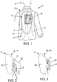
- the Figures 1 to 3 represent the protective equipment 2 according to a first embodiment of the invention comprising a jacket 15 that can be worn by the user 1 to move or practice a sporting or recreational activity and in particular to ride a motorcycle, snowmobile , horse riding, microlight, delta wing flight, paragliding or other.
- the protective equipment 2 could include any other garment used for professional or domestic activities with a risk of falling or shock.
- the jacket 15 includes the airbag 5 shaped to protect the bust of the user 1.
- An example of such an airbag 5 is described in the document WO 2011/148350 .
- the airbag 5 comprises two rear protection portions 16 intended to extend on either side of the spine of the user 1. These two rear protection portions 16 may be connected at respective upper ends to an upper protection portion intended to extend in the vicinity of the neck of the user 1. Furthermore, the two rear protection portions may each be connected at a lower end to a front protective portion for s' extend to the torso of the user 1. For this purpose, a lateral protection portion 17 intended to extend over the size of the user 1 can connect the lower end of the rear protection portion 16 to the portion of the user. front protection.
- the airbag 5 can be integrated directly into the jacket 15 by being interposed between two layers of the jacket 15. Alternatively, it can be integrated with a lining removably mounted on the jacket 15 to cover the inner surface as described in the document WO 2014/125368 .
- the jacket 15 also includes a shell 18 having overall rigidity.
- This shell 18 is, in the first embodiment, formed by a dorsal 19.
- the dorsal 19 comprises a wall 20 whose rigidity can be obtained by any appropriate means, and in particular by a suitable choice of materials, a particular conformation or a combination of these.
- the dorsal 19 can be integrated directly into the jacket 15 or be mounted removably.
- the dorsal 19 is preferably disposed outside the airbag 5 with respect to the user 1.
- the dorsal 19 has an inner surface intended to be directed towards the user 1, and an outer surface opposite the inner surface.
- the airbag 5 and the dorsal 19 are then mounted on the jacket 15 so that the airbag 5 is facing the inner surface of the dorsal 19.
- the dorsal 19 is arranged so as to cover part of the two rear protection portions 16 and a space between them and facing which is the spine of the user 1.
- the dorsal 19 serves as support 3 for the tube 7 of the gas reservoir 6.
- the gas reservoir 6 is housed in a thickness of the wall 20 of the dorsal 19.
- a housing 21 arranged in the dorsal 19 is adapted to receive, removably, an insert 22 in the form of a frame.
- the tube 7 of the gas tank 6, for example of circular section, is constituted by a plane winding with substantially rectangular turns.
- the tube 7 comprises straight and curved tubular sections arranged and dimensioned so that the gas tank can be placed inside the frame of the insert 22.
- the tube 7 comprises a succession of straight and bent tubular sections arranged such that each curved tubular section connects two straight tubular sections extending perpendicularly with respect to each other.
- the straight tubular sections of each turn may have outer surfaces in contact with the outer surfaces of the straight tubular sections of the adjacent turn.
- One end of the tube 7 forming the discharge port 8 may be connected to the air bag, the other end being plugged in any suitable manner.
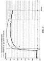
- the figure 4 is a curve illustrating the evolution as a function of time of a gas pressure at the gas tank outlet 6 according to an embodiment of the invention and at the outlet of a conventional gas cartridge.
- the gas tank 6 has a tube 7 14 mm in diameter and 530 mm in length.
- the tube is shaped so as to have a bent tubular section so as to form the plane winding with substantially rectangular turns represented on the Figures 1 to 3 .
- the cartridge meanwhile, has a tube 30 mm in diameter and 140 mm in length.
- the tube of the cartridge has a single straight tubular section.
- the tube 7 of the gas tank 6 according to the invention which can store a larger amount of gas than the cartridge, can quickly reach higher pressure levels.
- the Figures 5 to 7 represent a variant of the protective equipment 2 Figures 1 to 3 .
- the tube 10 of the gas reservoir 6 is integrated directly into a thickness of the backbone 19.
- the backbone 19 may comprise a wall 25 which is overmolded on the tube 10 of the gas reservoir 6.
- wall 25, for example obtained by injection of a polyurethane foam or other may have transverse streaks conferring a certain flexibility.
- the tube 10 of the gas reservoir 6 has straight and bent tubular sections arranged to form a single turn plane winding.
- Straight and bent tubular sections form an outer tubing 10a shaped to have a straight portion from a first discharge port 8 and a turn adjoining the straight portion to an inner end.
- Other straight and bent tubular sections form an inner tube 10b connected to the inner end of the outer tube 10a and extending parallel to the outer tube 10a to a second discharge port 8.
- the external tubing 10a and inner tubing 10b have bent tubular sections having different radii of curvature to connect straight tubular sections parallel to each other.
- the two exhaust ports 8 are connected to the airbag 5.
- the protection system 4 comprises two separate airbags 5 'disposed on either side of the gas tank 6.
- the tube 10 of the gas tank 6 is identical to the tube 10 described above in connection with the Figures 5 to 7 .
- the evacuation ports 8 are oriented in different directions, in this case opposite, to be each connected to one of the airbags 5 '.
- the actuating device 9 of such a system of protection 4 is then provided for, in the active state, put in fluid communication one of the exhaust ports 8 with the inner chamber of the airbag 5 'with which it is connected to inflate only one of the airbags 5' or the two exhaust ports 8 with the inner chambers of the airbags 5 'to inflate the two airbags 5'.
- Such a protection system finds particular application in the protection of the thighbone, only one of the airbags 5 ', suitably shaped to cover at least a portion of the hip of the user 1, which can be inflated in function of the shock side.
- the protection system 4 can be modified in such a way that only one of the ends of the tube 10 of the gas tank 6, for example that of the outer pipe 10a, forms an evacuation orifice 8 connected to both airbags.
- the other end of the tube 10 of the gas tank 6, for example that of the inner pipe 10b, may then have an opening provided with a filling valve 23 adapted to be connected to a gas supply source.
- a filling valve 23 adapted to be connected to a gas supply source.
- such an opening provided with a fill valve could be provided at any other appropriate location in the tube.
- the end of the tube 10 which is not connected to the airbags 5 'could be plugged in any suitable manner.
- the protection system 4 according to the second embodiment can be modified in such a way that the tube 10 of the gas reservoir 6 has adjoining tubular sections of different diameters.
- the outer pipe 10a has a curved tubular section 10c of greater diameter than the other tubular sections at the interface between the right part and the turn.
- the Figures 11 and 12 illustrate protective equipment 2 according to a third embodiment adapted, such as that of the second embodiment, in particular to the protection of the thigh neck.
- the tube 11 of the gas tank 6 is shaped to be integrated with a support 3 that the user can wear, such as a belt 30.
- the protection system 4 comprises two separate airbags 5 'and respectively connected to the discharge ports 8 of the tube 11 of the gas reservoir 6 so as to be inflated independently of one another or jointly.
- the tube 11 of the gas reservoir 6 comprises a curved tubular section whose radius of curvature varies to form a plane winding contiguous turns, the outer surface of a turn being in contact with that of the adjacent turn.
- the gas generator 6 can thus be placed in a portion of the belt corresponding to the back of the user 1.
- the Figures 13 to 15 represent protective equipment according to a fourth embodiment of the invention made in the form of a helmet 35.
- the protection system 4 integrated in the helmet comprises an airbag 5 ", a gas tank 6 placed in a thickness d a wall 36 of the helmet 35 and an actuating device 9.
- the gas reservoir 6 comprises a tube 12 constituted by a curved tubular section whose central axis A has two curvatures C1, C2 respectively extending in two directions. secant and, in particular, perpendicular planes and one of which C1 varies to form a spiral placed in a part of the wall 36 of the helmet 35 covering the top of the skull of the user 1.
- the Figures 16 and 17 represent a gas reservoir 6 of an equipment according to a fifth embodiment of the invention.
- the gas tank 6 comprises a tube 13 shaped so as to delimit a housing.
- the tube 13 of the gas reservoir 6 comprises a curved tubular section whose central axis A has two curvatures C1, C2 extending respectively in two secant planes and one of which C1 varies to form a first planar winding 13a with contiguous turns forming a bottom, a second winding 13b cylindrical contiguous turns forming a side wall.
- the gas reservoir 6 then forms a support or at least a part thereof.
- the tube 13 may have a square section to improve the support function.
- the gas tank 6 can be used in protective equipment for an article to be protected placed in the housing.
- the invention is not limited to the conformations and arrangements of the tube 7, 10, 11, 12, 13 of the gas generator 6 described above in connection with the particular embodiments.
- the invention is also not limited to a protection system 4 whose gas generator 6 comprises a single tube 7, 10, 11, 12, 13.
- the gas reservoir 6 could comprise a plurality of tubes, arranged and shaped to any suitable manner, and a manifold into which the outlets 8 of the tubes 7, 10, 11, 12, 13 open.
- the Figures 18 and 19 represent a gas reservoir 6 of an equipment according to a sixth embodiment of the invention.
- the gas reservoir 6 is in the form of a flat cartridge having two curvatures in two secant planes.
- the reservoir of gas 6 comprises a plurality of parallel tubes 30 each constituted by a bent tube section. Each of these bent tube sections has a first curvature C1 in a first plane.
- the tubes 30 are, moreover, arranged so as to define a second curvature C2 in a second plane perpendicular to the first plane.
- the discharge openings 8 at the ends of the tubes 30 open respectively into two collectors 31 extending transversely relative to the tubes.
- Each of the collectors 31 is then constituted by a section of curved tube having my second curvature C2.
- the collectors 31 then each open outwardly via a connector 32 adapted to be connected to an airbag via an actuating device.
- Such a gas tank 6 can be obtained by molding two plastic tank halves each comprising one half of the bent tubular sections 31 and one half of the manifolds 32. The two tank halves are then superimposed and a plastic layer is overmolded. on the two superimposed tank halves to hermetically assemble them.
- the invention applies, for example, to an inflatable structure such as a tent whose armature is constituted by one or more airbags.
Landscapes
- Health & Medical Sciences (AREA)
- General Health & Medical Sciences (AREA)
- Physical Education & Sports Medicine (AREA)
- Engineering & Computer Science (AREA)
- Textile Engineering (AREA)
- Air Bags (AREA)
- Filling Or Discharging Of Gas Storage Vessels (AREA)
Applications Claiming Priority (1)
| Application Number | Priority Date | Filing Date | Title |
|---|---|---|---|
| FR1654676A FR3051631B1 (fr) | 2016-05-25 | 2016-05-25 | Systeme deployable et equipement comprenant un tel systeme deployable |
Publications (2)
| Publication Number | Publication Date |
|---|---|
| EP3248491A1 true EP3248491A1 (de) | 2017-11-29 |
| EP3248491B1 EP3248491B1 (de) | 2019-03-27 |
Family
ID=56404189
Family Applications (1)
| Application Number | Title | Priority Date | Filing Date |
|---|---|---|---|
| EP17172651.6A Active EP3248491B1 (de) | 2016-05-25 | 2017-05-24 | Klappsystem und ausstattung, die ein solches klappsystem umfasst |
Country Status (2)
| Country | Link |
|---|---|
| EP (1) | EP3248491B1 (de) |
| FR (1) | FR3051631B1 (de) |
Cited By (1)
| Publication number | Priority date | Publication date | Assignee | Title |
|---|---|---|---|---|
| EP4046513B1 (de) | 2021-02-18 | 2024-01-03 | D-Air Lab S.r.l. | Hülle für eine gaspatrone |
Families Citing this family (1)
| Publication number | Priority date | Publication date | Assignee | Title |
|---|---|---|---|---|
| US20220134148A1 (en) * | 2020-11-05 | 2022-05-05 | Bradley Zang | Support System Using Electro-Viscous Fluid |
Citations (2)
| Publication number | Priority date | Publication date | Assignee | Title |
|---|---|---|---|---|
| EP0051254A1 (de) * | 1980-10-27 | 1982-05-12 | Alfred Kroiss | Motorradbekleidung |
| WO2011148350A1 (en) * | 2010-05-28 | 2011-12-01 | Helite S.A.R.L. | Protective garment with an airbag |
-
2016
- 2016-05-25 FR FR1654676A patent/FR3051631B1/fr active Active
-
2017
- 2017-05-24 EP EP17172651.6A patent/EP3248491B1/de active Active
Patent Citations (2)
| Publication number | Priority date | Publication date | Assignee | Title |
|---|---|---|---|---|
| EP0051254A1 (de) * | 1980-10-27 | 1982-05-12 | Alfred Kroiss | Motorradbekleidung |
| WO2011148350A1 (en) * | 2010-05-28 | 2011-12-01 | Helite S.A.R.L. | Protective garment with an airbag |
Cited By (1)
| Publication number | Priority date | Publication date | Assignee | Title |
|---|---|---|---|---|
| EP4046513B1 (de) | 2021-02-18 | 2024-01-03 | D-Air Lab S.r.l. | Hülle für eine gaspatrone |
Also Published As
| Publication number | Publication date |
|---|---|
| FR3051631A1 (fr) | 2017-12-01 |
| EP3248491B1 (de) | 2019-03-27 |
| FR3051631B1 (fr) | 2019-08-23 |
Similar Documents
| Publication | Publication Date | Title |
|---|---|---|
| EP3790422B1 (de) | Schutzhelm mit mechanischem grössenverstellsystem | |
| EP0061398B1 (de) | Verfahren und Vorrichtung zum Speichern und Ausklinken von zylindrischen Objekten in Fahrzeugen | |
| EP3248491B1 (de) | Klappsystem und ausstattung, die ein solches klappsystem umfasst | |
| FR2972423A1 (fr) | Procede et systeme de lancement d'un satellite | |
| FR3018581A1 (fr) | Capotage avec rebord de protection de l'organe de commande rotatif d'un bloc robinet de recipient de gaz | |
| FR2976048A1 (fr) | Chapeau de protection pour robinet de reservoir de fluide sous pression | |
| EP2779852B1 (de) | Schutzhelm mit einem einschlagsindikator | |
| FR2843621A1 (fr) | Dispositif de securite du type coussin gonflable | |
| EP3778313B1 (de) | Schutzsystem, babysitz und anwendung zur umsetzung dieses schutzsystems | |
| EP3609777B1 (de) | Boje | |
| FR3106115A1 (fr) | Dispositif de sécurité de volant de véhicule | |
| FR2780819A1 (fr) | Reflecteur d'antenne elastiquement deformable pour engin spatial | |
| FR3134156A1 (fr) | Double enceinte pour l’absorption d’une augmentation de pression | |
| EP2478796A1 (de) | Schutzvorrichtung für Tischbeine | |
| WO2016016249A1 (fr) | Systeme de protection pour dispositif de communication mobile et procede d'installation de ce systeme de protection | |
| EP2246217B1 (de) | Vorrichtung zum Verstauen einer Sicherheitsweste in der Kopfstütze einer Fahrzeugsitzrückenlehne | |
| WO2025163263A1 (fr) | Dispositif de contrôle de degonflage de poche de l'airbag | |
| WO2019202254A2 (fr) | Embarcation gonflable comportant un organe de flottaison, une unité de direction et une unité de propulsion | |
| WO2023186990A1 (fr) | Double enceinte pour l'absorption d'une augmentation de pression | |
| CH707903A2 (fr) | Sac pour dispositif portable de gonflage rapide d'une poche. | |
| WO2026047178A1 (fr) | Dispositif de compensation de pression pour réservoir à carburant | |
| FR3054311B1 (fr) | Grenade rechargeable a propulsion de billes | |
| EP2425727A1 (de) | Fallschutzvorrichtung für eine Person, insbesondere für den Benutzer eines Zweirads | |
| FR2990674A1 (fr) | Armature de volant de direction deformable | |
| FR3136844A1 (fr) | Ensemble de rangement |
Legal Events
| Date | Code | Title | Description |
|---|---|---|---|
| PUAI | Public reference made under article 153(3) epc to a published international application that has entered the european phase |
Free format text: ORIGINAL CODE: 0009012 |
|
| STAA | Information on the status of an ep patent application or granted ep patent |
Free format text: STATUS: THE APPLICATION HAS BEEN PUBLISHED |
|
| AK | Designated contracting states |
Kind code of ref document: A1 Designated state(s): AL AT BE BG CH CY CZ DE DK EE ES FI FR GB GR HR HU IE IS IT LI LT LU LV MC MK MT NL NO PL PT RO RS SE SI SK SM TR |
|
| AX | Request for extension of the european patent |
Extension state: BA ME |
|
| STAA | Information on the status of an ep patent application or granted ep patent |
Free format text: STATUS: REQUEST FOR EXAMINATION WAS MADE |
|
| 17P | Request for examination filed |
Effective date: 20180511 |
|
| RBV | Designated contracting states (corrected) |
Designated state(s): AL AT BE BG CH CY CZ DE DK EE ES FI FR GB GR HR HU IE IS IT LI LT LU LV MC MK MT NL NO PL PT RO RS SE SI SK SM TR |
|
| GRAP | Despatch of communication of intention to grant a patent |
Free format text: ORIGINAL CODE: EPIDOSNIGR1 |
|
| STAA | Information on the status of an ep patent application or granted ep patent |
Free format text: STATUS: GRANT OF PATENT IS INTENDED |
|
| INTG | Intention to grant announced |
Effective date: 20181022 |
|
| GRAS | Grant fee paid |
Free format text: ORIGINAL CODE: EPIDOSNIGR3 |
|
| GRAA | (expected) grant |
Free format text: ORIGINAL CODE: 0009210 |
|
| STAA | Information on the status of an ep patent application or granted ep patent |
Free format text: STATUS: THE PATENT HAS BEEN GRANTED |
|
| AK | Designated contracting states |
Kind code of ref document: B1 Designated state(s): AL AT BE BG CH CY CZ DE DK EE ES FI FR GB GR HR HU IE IS IT LI LT LU LV MC MK MT NL NO PL PT RO RS SE SI SK SM TR |
|
| REG | Reference to a national code |
Ref country code: GB Ref legal event code: FG4D Free format text: NOT ENGLISH |
|
| REG | Reference to a national code |
Ref country code: CH Ref legal event code: EP |
|
| REG | Reference to a national code |
Ref country code: AT Ref legal event code: REF Ref document number: 1111938 Country of ref document: AT Kind code of ref document: T Effective date: 20190415 |
|
| REG | Reference to a national code |
Ref country code: IE Ref legal event code: FG4D Free format text: LANGUAGE OF EP DOCUMENT: FRENCH |
|
| REG | Reference to a national code |
Ref country code: DE Ref legal event code: R096 Ref document number: 602017002902 Country of ref document: DE |
|
| PG25 | Lapsed in a contracting state [announced via postgrant information from national office to epo] |
Ref country code: FI Free format text: LAPSE BECAUSE OF FAILURE TO SUBMIT A TRANSLATION OF THE DESCRIPTION OR TO PAY THE FEE WITHIN THE PRESCRIBED TIME-LIMIT Effective date: 20190327 Ref country code: LT Free format text: LAPSE BECAUSE OF FAILURE TO SUBMIT A TRANSLATION OF THE DESCRIPTION OR TO PAY THE FEE WITHIN THE PRESCRIBED TIME-LIMIT Effective date: 20190327 Ref country code: SE Free format text: LAPSE BECAUSE OF FAILURE TO SUBMIT A TRANSLATION OF THE DESCRIPTION OR TO PAY THE FEE WITHIN THE PRESCRIBED TIME-LIMIT Effective date: 20190327 Ref country code: NO Free format text: LAPSE BECAUSE OF FAILURE TO SUBMIT A TRANSLATION OF THE DESCRIPTION OR TO PAY THE FEE WITHIN THE PRESCRIBED TIME-LIMIT Effective date: 20190627 |
|
| REG | Reference to a national code |
Ref country code: NL Ref legal event code: MP Effective date: 20190327 |
|
| PG25 | Lapsed in a contracting state [announced via postgrant information from national office to epo] |
Ref country code: GR Free format text: LAPSE BECAUSE OF FAILURE TO SUBMIT A TRANSLATION OF THE DESCRIPTION OR TO PAY THE FEE WITHIN THE PRESCRIBED TIME-LIMIT Effective date: 20190628 Ref country code: BG Free format text: LAPSE BECAUSE OF FAILURE TO SUBMIT A TRANSLATION OF THE DESCRIPTION OR TO PAY THE FEE WITHIN THE PRESCRIBED TIME-LIMIT Effective date: 20190627 Ref country code: RS Free format text: LAPSE BECAUSE OF FAILURE TO SUBMIT A TRANSLATION OF THE DESCRIPTION OR TO PAY THE FEE WITHIN THE PRESCRIBED TIME-LIMIT Effective date: 20190327 Ref country code: HR Free format text: LAPSE BECAUSE OF FAILURE TO SUBMIT A TRANSLATION OF THE DESCRIPTION OR TO PAY THE FEE WITHIN THE PRESCRIBED TIME-LIMIT Effective date: 20190327 Ref country code: LV Free format text: LAPSE BECAUSE OF FAILURE TO SUBMIT A TRANSLATION OF THE DESCRIPTION OR TO PAY THE FEE WITHIN THE PRESCRIBED TIME-LIMIT Effective date: 20190327 Ref country code: NL Free format text: LAPSE BECAUSE OF FAILURE TO SUBMIT A TRANSLATION OF THE DESCRIPTION OR TO PAY THE FEE WITHIN THE PRESCRIBED TIME-LIMIT Effective date: 20190327 |
|
| REG | Reference to a national code |
Ref country code: AT Ref legal event code: MK05 Ref document number: 1111938 Country of ref document: AT Kind code of ref document: T Effective date: 20190327 |
|
| PG25 | Lapsed in a contracting state [announced via postgrant information from national office to epo] |
Ref country code: SK Free format text: LAPSE BECAUSE OF FAILURE TO SUBMIT A TRANSLATION OF THE DESCRIPTION OR TO PAY THE FEE WITHIN THE PRESCRIBED TIME-LIMIT Effective date: 20190327 Ref country code: RO Free format text: LAPSE BECAUSE OF FAILURE TO SUBMIT A TRANSLATION OF THE DESCRIPTION OR TO PAY THE FEE WITHIN THE PRESCRIBED TIME-LIMIT Effective date: 20190327 Ref country code: CZ Free format text: LAPSE BECAUSE OF FAILURE TO SUBMIT A TRANSLATION OF THE DESCRIPTION OR TO PAY THE FEE WITHIN THE PRESCRIBED TIME-LIMIT Effective date: 20190327 Ref country code: ES Free format text: LAPSE BECAUSE OF FAILURE TO SUBMIT A TRANSLATION OF THE DESCRIPTION OR TO PAY THE FEE WITHIN THE PRESCRIBED TIME-LIMIT Effective date: 20190327 Ref country code: PT Free format text: LAPSE BECAUSE OF FAILURE TO SUBMIT A TRANSLATION OF THE DESCRIPTION OR TO PAY THE FEE WITHIN THE PRESCRIBED TIME-LIMIT Effective date: 20190727 Ref country code: EE Free format text: LAPSE BECAUSE OF FAILURE TO SUBMIT A TRANSLATION OF THE DESCRIPTION OR TO PAY THE FEE WITHIN THE PRESCRIBED TIME-LIMIT Effective date: 20190327 Ref country code: AL Free format text: LAPSE BECAUSE OF FAILURE TO SUBMIT A TRANSLATION OF THE DESCRIPTION OR TO PAY THE FEE WITHIN THE PRESCRIBED TIME-LIMIT Effective date: 20190327 |
|
| PG25 | Lapsed in a contracting state [announced via postgrant information from national office to epo] |
Ref country code: SM Free format text: LAPSE BECAUSE OF FAILURE TO SUBMIT A TRANSLATION OF THE DESCRIPTION OR TO PAY THE FEE WITHIN THE PRESCRIBED TIME-LIMIT Effective date: 20190327 Ref country code: PL Free format text: LAPSE BECAUSE OF FAILURE TO SUBMIT A TRANSLATION OF THE DESCRIPTION OR TO PAY THE FEE WITHIN THE PRESCRIBED TIME-LIMIT Effective date: 20190327 |
|
| PG25 | Lapsed in a contracting state [announced via postgrant information from national office to epo] |
Ref country code: IS Free format text: LAPSE BECAUSE OF FAILURE TO SUBMIT A TRANSLATION OF THE DESCRIPTION OR TO PAY THE FEE WITHIN THE PRESCRIBED TIME-LIMIT Effective date: 20190727 Ref country code: AT Free format text: LAPSE BECAUSE OF FAILURE TO SUBMIT A TRANSLATION OF THE DESCRIPTION OR TO PAY THE FEE WITHIN THE PRESCRIBED TIME-LIMIT Effective date: 20190327 |
|
| REG | Reference to a national code |
Ref country code: DE Ref legal event code: R097 Ref document number: 602017002902 Country of ref document: DE |
|
| PG25 | Lapsed in a contracting state [announced via postgrant information from national office to epo] |
Ref country code: MC Free format text: LAPSE BECAUSE OF FAILURE TO SUBMIT A TRANSLATION OF THE DESCRIPTION OR TO PAY THE FEE WITHIN THE PRESCRIBED TIME-LIMIT Effective date: 20190327 Ref country code: DK Free format text: LAPSE BECAUSE OF FAILURE TO SUBMIT A TRANSLATION OF THE DESCRIPTION OR TO PAY THE FEE WITHIN THE PRESCRIBED TIME-LIMIT Effective date: 20190327 |
|
| REG | Reference to a national code |
Ref country code: BE Ref legal event code: MM Effective date: 20190531 |
|
| PLBE | No opposition filed within time limit |
Free format text: ORIGINAL CODE: 0009261 |
|
| STAA | Information on the status of an ep patent application or granted ep patent |
Free format text: STATUS: NO OPPOSITION FILED WITHIN TIME LIMIT |
|
| PG25 | Lapsed in a contracting state [announced via postgrant information from national office to epo] |
Ref country code: LU Free format text: LAPSE BECAUSE OF NON-PAYMENT OF DUE FEES Effective date: 20190524 Ref country code: SI Free format text: LAPSE BECAUSE OF FAILURE TO SUBMIT A TRANSLATION OF THE DESCRIPTION OR TO PAY THE FEE WITHIN THE PRESCRIBED TIME-LIMIT Effective date: 20190327 |
|
| 26N | No opposition filed |
Effective date: 20200103 |
|
| PG25 | Lapsed in a contracting state [announced via postgrant information from national office to epo] |
Ref country code: TR Free format text: LAPSE BECAUSE OF FAILURE TO SUBMIT A TRANSLATION OF THE DESCRIPTION OR TO PAY THE FEE WITHIN THE PRESCRIBED TIME-LIMIT Effective date: 20190327 |
|
| PG25 | Lapsed in a contracting state [announced via postgrant information from national office to epo] |
Ref country code: IE Free format text: LAPSE BECAUSE OF NON-PAYMENT OF DUE FEES Effective date: 20190524 |
|
| PG25 | Lapsed in a contracting state [announced via postgrant information from national office to epo] |
Ref country code: BE Free format text: LAPSE BECAUSE OF NON-PAYMENT OF DUE FEES Effective date: 20190531 |
|
| PG25 | Lapsed in a contracting state [announced via postgrant information from national office to epo] |
Ref country code: LI Free format text: LAPSE BECAUSE OF NON-PAYMENT OF DUE FEES Effective date: 20200531 Ref country code: CH Free format text: LAPSE BECAUSE OF NON-PAYMENT OF DUE FEES Effective date: 20200531 |
|
| PG25 | Lapsed in a contracting state [announced via postgrant information from national office to epo] |
Ref country code: CY Free format text: LAPSE BECAUSE OF FAILURE TO SUBMIT A TRANSLATION OF THE DESCRIPTION OR TO PAY THE FEE WITHIN THE PRESCRIBED TIME-LIMIT Effective date: 20190327 |
|
| PG25 | Lapsed in a contracting state [announced via postgrant information from national office to epo] |
Ref country code: MT Free format text: LAPSE BECAUSE OF FAILURE TO SUBMIT A TRANSLATION OF THE DESCRIPTION OR TO PAY THE FEE WITHIN THE PRESCRIBED TIME-LIMIT Effective date: 20190327 Ref country code: HU Free format text: LAPSE BECAUSE OF FAILURE TO SUBMIT A TRANSLATION OF THE DESCRIPTION OR TO PAY THE FEE WITHIN THE PRESCRIBED TIME-LIMIT; INVALID AB INITIO Effective date: 20170524 |
|
| PG25 | Lapsed in a contracting state [announced via postgrant information from national office to epo] |
Ref country code: MK Free format text: LAPSE BECAUSE OF FAILURE TO SUBMIT A TRANSLATION OF THE DESCRIPTION OR TO PAY THE FEE WITHIN THE PRESCRIBED TIME-LIMIT Effective date: 20190327 |
|
| PGFP | Annual fee paid to national office [announced via postgrant information from national office to epo] |
Ref country code: DE Payment date: 20250513 Year of fee payment: 9 |
|
| PGFP | Annual fee paid to national office [announced via postgrant information from national office to epo] |
Ref country code: GB Payment date: 20250521 Year of fee payment: 9 |
|
| PGFP | Annual fee paid to national office [announced via postgrant information from national office to epo] |
Ref country code: IT Payment date: 20250508 Year of fee payment: 9 |
|
| PGFP | Annual fee paid to national office [announced via postgrant information from national office to epo] |
Ref country code: FR Payment date: 20260316 Year of fee payment: 10 |