EP3248523A2 - Distributeur de fluide ayant un capteur de proximité de durée de vol - Google Patents
Distributeur de fluide ayant un capteur de proximité de durée de vol Download PDFInfo
- Publication number
- EP3248523A2 EP3248523A2 EP17170086.7A EP17170086A EP3248523A2 EP 3248523 A2 EP3248523 A2 EP 3248523A2 EP 17170086 A EP17170086 A EP 17170086A EP 3248523 A2 EP3248523 A2 EP 3248523A2
- Authority
- EP
- European Patent Office
- Prior art keywords
- dispenser
- sensor
- distance
- time
- controller
- Prior art date
- Legal status (The legal status is an assumption and is not a legal conclusion. Google has not performed a legal analysis and makes no representation as to the accuracy of the status listed.)
- Granted
Links
Images


Classifications
-
- A—HUMAN NECESSITIES
- A47—FURNITURE; DOMESTIC ARTICLES OR APPLIANCES; COFFEE MILLS; SPICE MILLS; SUCTION CLEANERS IN GENERAL
- A47K—SANITARY EQUIPMENT; ACCESSORIES THEREFOR, e.g. TOILET ACCESSORIES
- A47K5/00—Holders or dispensers for soap, toothpaste or the like
- A47K5/06—Dispensers for soap
- A47K5/12—Dispensers for soap for liquid or pasty soap
- A47K5/1217—Electrical control means for the dispensing mechanism
-
- A—HUMAN NECESSITIES
- A47—FURNITURE; DOMESTIC ARTICLES OR APPLIANCES; COFFEE MILLS; SPICE MILLS; SUCTION CLEANERS IN GENERAL
- A47K—SANITARY EQUIPMENT; ACCESSORIES THEREFOR, e.g. TOILET ACCESSORIES
- A47K10/00—Body-drying implements; Toilet paper; Holders therefor
- A47K10/24—Towel dispensers; Toilet paper dispensers
- A47K10/32—Dispensers for paper towels or toilet paper
- A47K10/34—Dispensers for paper towels or toilet paper dispensing from a web, e.g. with mechanical dispensing means
- A47K10/38—Dispensers for paper towels or toilet paper dispensing from a web, e.g. with mechanical dispensing means the web being rolled-up
-
- A—HUMAN NECESSITIES
- A47—FURNITURE; DOMESTIC ARTICLES OR APPLIANCES; COFFEE MILLS; SPICE MILLS; SUCTION CLEANERS IN GENERAL
- A47K—SANITARY EQUIPMENT; ACCESSORIES THEREFOR, e.g. TOILET ACCESSORIES
- A47K10/00—Body-drying implements; Toilet paper; Holders therefor
- A47K10/24—Towel dispensers; Toilet paper dispensers
- A47K10/32—Dispensers for paper towels or toilet paper
- A47K10/42—Dispensers for paper towels or toilet paper dispensing from a store of single sheets, e.g. stacked
-
- A—HUMAN NECESSITIES
- A47—FURNITURE; DOMESTIC ARTICLES OR APPLIANCES; COFFEE MILLS; SPICE MILLS; SUCTION CLEANERS IN GENERAL
- A47K—SANITARY EQUIPMENT; ACCESSORIES THEREFOR, e.g. TOILET ACCESSORIES
- A47K10/00—Body-drying implements; Toilet paper; Holders therefor
- A47K10/24—Towel dispensers; Toilet paper dispensers
- A47K10/32—Dispensers for paper towels or toilet paper
- A47K10/46—Dispensers for paper towels or toilet paper with means for storing soiled towels
-
- B—PERFORMING OPERATIONS; TRANSPORTING
- B65—CONVEYING; PACKING; STORING; HANDLING THIN OR FILAMENTARY MATERIAL
- B65F—GATHERING OR REMOVAL OF DOMESTIC OR LIKE REFUSE
- B65F1/00—Refuse receptacles; Accessories therefor
- B65F1/14—Other constructional features; Accessories
-
- G—PHYSICS
- G01—MEASURING; TESTING
- G01S—RADIO DIRECTION-FINDING; RADIO NAVIGATION; DETERMINING DISTANCE OR VELOCITY BY USE OF RADIO WAVES; LOCATING OR PRESENCE-DETECTING BY USE OF THE REFLECTION OR RERADIATION OF RADIO WAVES; ANALOGOUS ARRANGEMENTS USING OTHER WAVES
- G01S17/00—Systems using the reflection or reradiation of electromagnetic waves other than radio waves, e.g. lidar systems
- G01S17/02—Systems using the reflection of electromagnetic waves other than radio waves
- G01S17/06—Systems determining position data of a target
- G01S17/08—Systems determining position data of a target for measuring distance only
-
- G—PHYSICS
- G01—MEASURING; TESTING
- G01S—RADIO DIRECTION-FINDING; RADIO NAVIGATION; DETERMINING DISTANCE OR VELOCITY BY USE OF RADIO WAVES; LOCATING OR PRESENCE-DETECTING BY USE OF THE REFLECTION OR RERADIATION OF RADIO WAVES; ANALOGOUS ARRANGEMENTS USING OTHER WAVES
- G01S17/00—Systems using the reflection or reradiation of electromagnetic waves other than radio waves, e.g. lidar systems
- G01S17/88—Lidar systems specially adapted for specific applications
-
- A—HUMAN NECESSITIES
- A47—FURNITURE; DOMESTIC ARTICLES OR APPLIANCES; COFFEE MILLS; SPICE MILLS; SUCTION CLEANERS IN GENERAL
- A47K—SANITARY EQUIPMENT; ACCESSORIES THEREFOR, e.g. TOILET ACCESSORIES
- A47K10/00—Body-drying implements; Toilet paper; Holders therefor
- A47K10/24—Towel dispensers; Toilet paper dispensers
- A47K10/32—Dispensers for paper towels or toilet paper
- A47K2010/3226—Dispensers for paper towels or toilet paper collecting data of usage
-
- B—PERFORMING OPERATIONS; TRANSPORTING
- B65—CONVEYING; PACKING; STORING; HANDLING THIN OR FILAMENTARY MATERIAL
- B65F—GATHERING OR REMOVAL OF DOMESTIC OR LIKE REFUSE
- B65F2210/00—Equipment of refuse receptacles
- B65F2210/144—Level detecting means
- B65F2210/1443—Electrical
-
- B—PERFORMING OPERATIONS; TRANSPORTING
- B65—CONVEYING; PACKING; STORING; HANDLING THIN OR FILAMENTARY MATERIAL
- B65F—GATHERING OR REMOVAL OF DOMESTIC OR LIKE REFUSE
- B65F2240/00—Types of refuse collected
- B65F2240/156—Paper
- B65F2240/1568—Towels
-
- Y—GENERAL TAGGING OF NEW TECHNOLOGICAL DEVELOPMENTS; GENERAL TAGGING OF CROSS-SECTIONAL TECHNOLOGIES SPANNING OVER SEVERAL SECTIONS OF THE IPC; TECHNICAL SUBJECTS COVERED BY FORMER USPC CROSS-REFERENCE ART COLLECTIONS [XRACs] AND DIGESTS
- Y02—TECHNOLOGIES OR APPLICATIONS FOR MITIGATION OR ADAPTATION AGAINST CLIMATE CHANGE
- Y02W—CLIMATE CHANGE MITIGATION TECHNOLOGIES RELATED TO WASTEWATER TREATMENT OR WASTE MANAGEMENT
- Y02W30/00—Technologies for solid waste management
- Y02W30/50—Reuse, recycling or recovery technologies
- Y02W30/64—Paper recycling
Definitions
- This invention relates to the use of precise distance measuring sensors in washroom appliances including notably in a triggering mechanism for a liquid dispenser and in monitoring the supply level in paper towel dispensers and toilet paper dispensers and in measuring the extent to which a waste bin or spool are empty.
- Known touchless dispensers of hand cleaning fluids are triggered by sensors which measure relative changes of environmental conditions such as in the case of known infrared sensors, optical reflectants and, in the case of capacitive sensors, the change of a capacitive field around the sensors.
- sensors typically measure a relative change of the environmental conditions within a certain time frame.
- infrared sensors and capacitive sensors suffer a number of disadvantages. For example, infrared sensors are often rendered inoperative due to infrared radiation which may arise and change in the environment. Capacitive sensors may have difficulty measuring the change in capacitive fields depending upon the environmental conditions.
- Some known touchless dispensers provide for a number of different sensors to control different features. For example, one infrared sensor may determine the presence of a user's hand below a fluid outlet and another infrared sensor may be provided on the dispenser at a different location as to sense hand gestures as delivered by movement of a user's second hand above the dispenser, for example, to dispense an additional dosage of liquid.
- sensors for paper towel dispensers and toilet paper dispensers merely determine the signal condition such as, for example, an empty condition and do not provide other information useful for the control and management of the dispenser.
- sensors used to sense the level of waste within a waste bin typically provide input on but a single condition such as, for example, a full condition and suffer the disadvantage they do not provide other information by a single sensor which can be useful in the control and management of waste bins.
- the present invention provides for the use of a precise distance measuring sensor for various applications including the triggering of a liquid dispenser, and the determining of the level of supply of disposable product in a dispenser such as a paper towel dispenser and a toilet paper dispenser and in the determination of the extent to which a waste bin is full.
- the present invention provides a precise distance measuring sensor such as a time of flight sensor is used to measure the distance between the sensor and a target object precisely over time to develop useful feedback for the operation, control and management of appliances including hand cleaning liquid dispensers, paper towel dispensers, toilet paper dispensers and waste bins.
- the accurate distance measuring sensors are used to trigger the dispensing of a consumable product such as a hand cleaning product, paper towel and toilet paper.
- the triggering can arise by the sensor activating the dispenser to dispense product when the user's hand is sensed to be within a predetermined range of distances from an outlet of the product and/or to recognize hand gestures of a hand of a user towards controlling dispensing based on the hand gestures of a user.
- the present invention provides a hand cleaning fluid dispenser for dispensing fluid onto a user's hand, the dispenser including a time of flight sensor to determine a distance of a hand of a user below an outlet of the dispenser from which the dispenser when activated dispenses the fluid; the dispenser including a controller to activate the dispenser to dispense the fluid from the outlet when the hand is sensed to be within a predetermined range of distances below the outlet.
- the controller activates the dispenser to dispense a first dose of fluid when a hand is first sensed to be within the predetermined range of distances.
- the controller activates the dispenser such that after dispensing the first dose of fluid, the hand is sensed to be moved from within a first pre-set range of distances below the outlet to a second range of distances below the outlet and then back to the first range of distances below the outlet.
- the controller controls the frequency of operation of the time of flight sensor that the time of flight sensor operates to determine the distance of the hand below the outlet.
- the time of flight sensor on failing to sense a moving object within a predetermined scanning volume within a first period of time activating the sensor to scan at a frequency with a first time interval between scans provided no moving object has been sensed by the sensor for a first period of time, the controller controlling the sensor such that after a moving object has been sensed by the sensor, the sensor is activated with a second period of time between sensing and, if the sensor senses an object within a predetermined range of distances below the outlet, the controller activates the sensor for sensing at a third time interval between sensing, the third time interval being smaller than the second time interval and the second time interval being smaller than the first time interval.
- the dispenser is powered by a battery and the controller controls the operation of the flight sensor to reduce the consumption of the electrical power from the battery by reducing the frequency that the sensor is activated to sense moving objects.
- the dispenser includes a reservoir containing the fluid to be dispensed, a pump for dispensing fluid from the reservoir out the outlet and onto the user's hand.
- the present invention provides a fluid dispenser including:
- the present invention provides a paper dispenser including:
- the present invention provides a refuse bin including:
- the invention provides as a 4 th feature a hand cleaning fluid dispenser for dispensing fluid onto a user's hand, the dispenser including a time of flight sensor to determine at successive times a distance of a moving object relative an outlet of the dispenser from which the dispenser when activated dispenses the fluid; the dispenser including a controller to activate the dispenser to dispense the fluid from the outlet when the distance of the moving object is sensed to be within a first set of predetermined distances below the outlet that fluid dispensed from the outlet will engage the moving object.
- the invention provides as a 5 th feature, as in the 4 th feature, a hand cleaning fluid dispenser wherein the controller activates the dispenser to dispense a first dose of fluid when the moving object is first sensed to be within the first set of predetermined distances below the outlet.
- the invention provides as a 6 th feature, as in the 4 th or 5 th feature, a hand cleaning fluid dispenser in which the dispenser includes a battery, the dispenser is powered by the battery and the controller controls the operation of the flight sensor to reduce the consumption of the electrical power from the battery by changing the frequency that the sensor is activated to sense the distance of moving objects from the outlet.
- the invention provides as a 7 th feature, as in the 6 th feature, a hand cleaning fluid dispenser in which the controller changing the frequency that the sensor is activated to sense the distance of moving objects as a function of the distance of sensed.
- the invention provides as a 8 th feature, as in the 6 th or 7 th feature, a hand cleaning fluid dispenser wherein the controller increasing the frequency that the sensor is activated to sense a moving object as the distances sensed reduce and the controller decreasing the frequency that the sensor is activated to sense a moving object as the distances sense increase.
- the invention provides as a 9 th feature, as in any one of the 6 th to 8 th features, a hand cleaning fluid dispenser in which the controller changing the frequency that the sensor is activated to sense the distance of moving objects as a function of the time passed since the distance of a moving object was last sensed.
- the invention provides as a 10 th feature, as in the 9 th feature, a hand cleaning fluid dispenser wherein the controller increasing the frequency that the sensor is activated to sense a moving object as the time passed since the distance of a moving object was last sensed reduces and the controller decreasing the frequency that the sensor is activated to sense a moving object as the time passed since the distance of a moving object was last sensed increases.
- the invention provides as a 11 th feature, as in the 10 th feature, a hand cleaning fluid dispenser wherein:
- the invention provides as a 12 th feature, as in the 11 th feature, a hand cleaning fluid dispenser wherein:
- the invention provides as a 13 th feature, as in any one of the 4 th to 12 th features, a hand cleaning fluid dispenser wherein the dispenser includes a reservoir containing the fluid to be dispensed, a pump for dispensing fluid from the reservoir out the outlet and onto the user's hand.
- the invention provides as a 14 th feature, a device having a consumable attribute which is consumed during use and which is replaceable, the consumable attribute having a reference surface which varies in distance from a reference point as the consumable attribute is consumed, a time of flight sensor to determine a distance of the reference surface from the reference point, a controller to estimate the extent to which the consumable attribute is present in the device based on the distance determined by the sensor.
- the invention provides as a 15 th feature, as in the 14 th feature, a device wherein:
- the invention provides as a 16 th feature, as in the 15 th feature, a device wherein the dispenser comprises a fluid dispenser, the consumable material comprises a fluid, the fluid dispenser including reservoir containing the fluid, the fluid within the reservoir having an upper surface comprising the reference surface, the reference point being above the upper surface, the controller estimating the extent to which the reservoir is full or empty based on the distance determined by the sensor.
- the invention provides as a 17 th feature, as in the 15 th feature, a device wherein the dispenser comprises a paper dispenser, the consumable material comprises a paper supply comprising a roll of paper sheet material or a stack of paper sheet material, the paper supply having a surface of the paper sheet material comprising the reference surface, the controller estimating the extent to which the paper supply is full or empty based on the distance determined by the sensor.
- the dispenser comprises a paper dispenser
- the consumable material comprises a paper supply comprising a roll of paper sheet material or a stack of paper sheet material, the paper supply having a surface of the paper sheet material comprising the reference surface
- the controller estimating the extent to which the paper supply is full or empty based on the distance determined by the sensor.
- the invention provides as a 18 th feature, as in the 14 th feature, a device wherein:
- the invention provides as a 19 th feature, as in any one of the 14 th to 18 th features, a device wherein the device is powered by a battery and the controller controls operation of the time of flight sensor to reduce consumption of electrical power from the battery by changing the frequency that the sensor is activated to sense the reference surface as a function of the time passed since a change in the distance was last sensed.
- the invention provides as a 20 th feature, as in the 19 th feature, a device wherein:
- the invention provides as a 21 st feature, as in any one of the 14 th to 20 th features, a device wherein the controller has a communications capability to communicate to a remote computer data regarding the distances and time.
- the invention provides as a 22 nd feature, as in the 21 st feature, a device wherein the controller and/or the remote computer estimating when the distance will be representative of the consumable attribute being nil.
- the invention provides as a 23 rd feature, as in any one of the 14 th to 22 nd features, a device wherein the controller estimating when the distance will be representative of the consumable attribute being nil.
- the invention provides as a 24 th feature, a dispenser including:
- the invention provides as a 25 th feature, a refuse bin including:
- the invention provides as a 26 th feature, in combination, a paper dispenser and a refuse bin:
- the invention provides as a 27 th feature, as in the 26 th feature, the combination wherein:
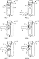
- FIG. 1 to 6 illustrate a touchless hand cleaning fluid dispenser 10.
- the fluid dispenser 10 is supported by a support structure, not shown, such as by being attached to a wall in a washroom or a wall in a hospital or supported from the floor as by a stand, not shown.
- the dispenser 10 includes a reservoir 11 containing a fluid to be dispensed and a discharge outlet 12 out of which the fluid is to be dispensed.
- the dispenser 10 is schematically illustrated as including a pump 13 to draw liquid via a dip tube 14 from the reservoir for dispensing of fluid downwardly out the discharge outlet 12.
- the dispenser 10 includes a controller 15, an electrical power source 16 comprising preferably a replaceable or rechargeable battery and a sensor 18.
- the controller 15 is electrically connected to the pump 13 and the sensor 18 and suitably delivers power from the battery 16 to the pump 13 and the sensor 18 to activate them.
- the sensor 18 is a precise distance measuring sensor, preferably a time of flight sensor which measures the distance between the sensor and a target object directly by measuring the flight time of photons transmitted from the sensor 18 that are reflected by a target to the sensor 18.
- the time of flight sensor 18 emits a very short light pulse and uses a photosensitive element such as a photo diode to sense the photons reflected by a target object back to the sensor 18.
- a time counter determines the flight time between the transmission of the light pulses and the sensing of the reflected light.
- Preferred precise distance measuring sensors preferably can measure the distance between the sensor and an object with the field of view of the sensor accurately, preferably, to distances of less than 100 millimeters, more preferably, 50 millimeters, more preferably, 5 millimeters and, more preferably, 1 millimeter.
- FIG. 1 to 8 show a preferred hand control operation of a liquid dispenser 10 utilizing a single sensor 18 in accordance with the present invention.
- Figure 1 illustrates a dormant condition of the dispenser 10.
- the dormant condition is a condition in which the sensor 18 does not detect any object moving within the field of view of the sensor 18 or at least within a preselected dormant distance, for example, within a radius of 18 inches from the sensor 18.
- the sensor 18 has a field of view that assesses the distance of a moving object from the outlet below the outlet.
- Figure 2 illustrates a condition in which a hand 9 of a user is moved within 18 inches of the sensor 18 and the movement of the hand is sensed by the sensor 18.
- the condition illustrated in Figure 2 is indicated as a ready condition.
- Figure 3 indicates an active condition of the dispenser in which the user's hand 9 has been moved so as to be located within a predetermined active range of distances below the outlet 12, for example, selected to be within the range of two to six inches below the outlet.
- the predetermined range or set of distances below the outlet is selected having regard to the field of view of the sensor to be such that fluid dispensed from the outlet will engage the user's hand.
- the controller 15 activates the pump 13 so as to dispense a single dose, preferably 1 milliliter of fluid onto the person's hand 9.
- Figure 4 illustrates a condition in which a first dose of fluid is being dispensed onto the user's hand 20.
- Figure 5 illustrates an additional active condition of the dispenser 10 in which from the position shown in Figure 4 , the hand 9 has been moved vertically downwardly such that the hand 9 remains within the active range of distances below the outlet 12 and then, subsequently, relatively abruptly, the hand 9 is move from the position of Figure 5 to the position of Figure 6 in which the hand 9 is in the substantially same position as in Figure 4 .
- the sensor 18 senses the vertical downward movement of the hand 9 from the position of Figure 4 to the position of Figure 5 and then subsequently from the position of Figure 5 to the position of Figure 6 within an acceptable period of time.
- the controller 15 on sensing this movement activates the pump 13 so as to dispense a second dose of fluid from the outlet 12 and
- Figure 6 illustrates a second dose of fluid being dispensed from the outlet 12 onto the hand of a user.
- Figure 5 illustrates the hand 9 of the user as carrying the first dose of fluid 8.
- the operation of the sensor 18 is controlled so as to attempt to reduce energy consumption by the sensor 18.
- the sensor 18 is activated by the controller 15 to scan at a relatively low frequency, for example, one to four scans per second or less so as to save electrical power.
- the controller 15 increases the scan rate of the sensor 18 as, for example, to eight scans per second. Preferably, with the scan rate at this intermediate scan rate of eight scans per second, the controller 15 uses the sensor 18 to determine if the hand 9 of a user is within the active range and will activate the pump 13 to dispense fluid.
- the controller 15 preferably increases the scan rate of the sensor 18 as, for example, to a gesture scan rate of, for example, about sixteen scans per second which gesture scan rate is selected such that the sensor 18 can detect the gestures of the hand 9, that is, for example, the movement of the hand 9 between the positions of Figures 4, 5 and 6 with time.
- the scan rate of the sensor 18 is the frequency that the sensor 18 is activated to scan for objects with time.
- the controller 15 controls the scan rate so as to reduce the scan rate and thereby save energy during dormant periods of time, increase the scan rate to provide for fluid activation during certain periods of time and, preferably, to further increase the scan rate at times when the sensor 18 is desired to detect gestures of the hand 9.
- a single sensor 18 is utilized and a single sensor is adequate to detect gestures of the hand dependent upon varying distances of the hand from the sensor 18.
- the senor 18 may comprise two, more preferably three sensors 18 which are mounted at different locations on the dispenser and can be used to detect three-dimensional gestures within a supervised volume about the dispenser represented by overlapping volumes in the view range of the sensors.
- two dots 118 and 218 are shown which could represent the location of a secondary and/or third time of flight sensor.
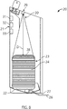
- FIG 8 schematically shows a cross-sectional side of a typical paper towel dispenser 20 consisting of a housing 21 supporting inside the housing on a lower shelf 22 of the housing a sack 23 of nested individual paper towels 24.
- the lowest-most towel 26 is dispensed out a discharge outlet 27 at a lower end of the housing 21, typically by being manually drawn out by a user.
- the dispenser 20 preferably includes a single time of flight sensor 29 emitting a beam 30 downwardly, a controller 31, a power source 32 and a communications device 33.
- the single time of flight sensor 29 is provided coupled to the housing 21 to measure the distance D of the top 28 of the stack 23 from the sensor 29 with time.
- the distance D of the top 28 of the stack 23 from the sensor 29 represents the supply of towels in the dispenser 20.
- Data representing the measured distances D with time as well as an identification of the specific dispenser are created and preferably stored and/or transmitted.
- the controller 31 not only controls operation of the sensor 29 but also preferably controls the transition of the data preferably to the communication device 33.
- the communication device could be a simple LED visible to servicing staff on the exterior of the housing and providing an indication of the supply of paper in the dispenser 20.
- the communication device 33 is a wireless communication device as to transmit the data wirelessly to a remote computer server, not shown, from which the data can be utilized to control maintenance of the dispenser 20, for example, as to be read by the servicing staff to determine when to refile the dispenser with paper towels, and to give notices and warnings as to low paper conditions.
- Such transmitted data is to be gathered and stored so as to provide not only the actual height of the paper stack and therefore the amount of available papers known at any time, but also the history and changes of the amount of paper in the dispenser over the time from which preferably patterns of intensity of usage can be determined.
- the monitoring of the data on usage with time can be used to predict when the dispenser is going to be empty.
- servicing staff are alerted and can know when a dispenser has to be refilled and the time and effort of servicing staff can be optimized as to reduce it to necessary actions.
- Figure 8 shows a paper towel dispenser with a stack of individual paper towels.
- Other paper dispensers are known in which the paper is dispensed from a roll. The distance of the radially outer surface of the paper on the roll can be measured with the time of flight sensor fixed point on the housing to determine the remaining radius of the roll which will correlate accurately the amount of paper supply on the roll in the dispenser.
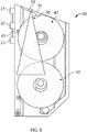
- Figure 9 schematically shows a cross-sectional side of a toilet paper dispenser 40 consisting of a housing 41 supporting inside the housing a spare upper roll 42 of toilet paper and an active lower roll 43 of toilet paper. While only the lower roll 43 need be provided, preferably, the upper roll 42 is placed supported on the lower roll 43 and falls into the location of the lower roll 43 when the lower roll 43 is used up.
- the dispenser 20 preferably includes a single time of flight sensor 29 emitting a beam 30 downwardly, a controller 31, a power source 32 and a communications device 33.
- the sensor 29 is mounted inside the top of a shroud 36, looking downwards to the paper rolls 42 and 43 and measuring the distance from the sensor 29 to the closest roll.
- the sensor 29 sees only the upper roll 42. When two rolls are in the dispenser, then the surface of the upper roll 42 is sensed as at an approximately constant distance. When only one roll is in the dispenser as in the lower position shown by lower roll 43, then the sensor 29 effectively measures the radius of the active lower roll 43 and thus provides an indication as to the paper remaining with time.
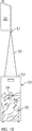
- FIG 11 schematically shows a cross-sectional side view of a waste bin 60 and an associated time of flight sensor 61.
- the bin 60 defines an interior cavity 62 bounded by circumferential side walls 63 and a bottom wall 64.
- An access opening 65 is provided into the cavity 60 via which refuse material 66 shown as used paper towels may be inserted into the bin 60 to form a pile 67 of the refuse within the cavity 62.
- the pile 67 is supported on the bottom wall 64 and constrained inside the side walls 63.
- the pile 67 has an upwardly directed uppermost surface or top 68.
- the time of flight sensor 61 is fixed at a reference point above the bin 60 such that the field of view of the time of flight sensor 61 is downward into the cavity 62 to measure the distance from the time of flight sensor 61 to the uppermost surface 68. By measuring this distance, the extent to which the bin 60 is filled can be determined at any time and over time.
- Figure 10 While not shown on Figure 11 , the arrangement of Figure 10 in a manner similar to Figure 9 preferably includes a controller, a power source and a communication device.
- the time of flight sensor 61 may preferably be secured to the waste bin 60 as onto a lid or cover 70 or the wall 57 of the bin 60.
- the access opening 65 is provided as upwardly opening through the cover 70 and horizontally through the walls 63.
- Figure 10 schematically shows a cross-sectional side view of a waste bin 50 preferably mounted below a separate time of flight sensor 51.
- a paper towel dispenser 20 such as in Figure 8
- the sensor 51 is mounted on the paper towel dispenser 52.
- the sensor 51 is mounted above the waste bin 50 so that its field of view is into the waste bin 51 through an upwardly opening 53 into the waste bin 50 from the top.
- the arrangement in Figure 10 in a similar manner to that in Figure 9 preferably includes a controller, a power source and a communications device, and when the sensor is on a dispenser 20 above the bin 54 which dispenser also has its own sensor 29, then the two sensors may be controlled by the same controller and share the same power source and communications device.
- the two sensors may be controlled by the same controller and share the same power source and communications device.
- only one controller, power supply, and communication device is required in the dispenser 20 to measure both the extent the dispenser reservoir contains fluid and the extent that the bin 50 contains waste paper.
- Figure 7 shows, using reference numbers the same as in Figure 8 , an arrangement for using a single time of flight sensor 29 to measure the distance D of the top surface 28 of fluid 23 in the reservoir 11 from the sensor 29 with time.
- the distance D of the top 28 of the fluid 23 from the sensor 29 represents the supply of liquid in the reservoir 11.
- the sensor 29 is preferably mounted as to a housing for the fluid dispenser such that the sensor is located at a reference point where the sensor can direct its beam onto the top surface 28 of fluid 23 in the reservoir.
Landscapes
- Health & Medical Sciences (AREA)
- Public Health (AREA)
- Physics & Mathematics (AREA)
- Engineering & Computer Science (AREA)
- Electromagnetism (AREA)
- Computer Networks & Wireless Communication (AREA)
- General Physics & Mathematics (AREA)
- Radar, Positioning & Navigation (AREA)
- Remote Sensing (AREA)
- Mechanical Engineering (AREA)
- Containers And Packaging Bodies Having A Special Means To Remove Contents (AREA)
- Details Of Rigid Or Semi-Rigid Containers (AREA)
Applications Claiming Priority (2)
| Application Number | Priority Date | Filing Date | Title |
|---|---|---|---|
| US201662333689P | 2016-05-09 | 2016-05-09 | |
| US201662411094P | 2016-10-21 | 2016-10-21 |
Publications (3)
| Publication Number | Publication Date |
|---|---|
| EP3248523A2 true EP3248523A2 (fr) | 2017-11-29 |
| EP3248523A3 EP3248523A3 (fr) | 2018-03-21 |
| EP3248523B1 EP3248523B1 (fr) | 2020-09-30 |
Family
ID=58692441
Family Applications (1)
| Application Number | Title | Priority Date | Filing Date |
|---|---|---|---|
| EP17170086.7A Active EP3248523B1 (fr) | 2016-05-09 | 2017-05-09 | Distributeur de fluide ayant un capteur de proximité de durée de vol |
Country Status (3)
| Country | Link |
|---|---|
| US (1) | US10278550B2 (fr) |
| EP (1) | EP3248523B1 (fr) |
| CA (1) | CA2965971C (fr) |
Cited By (7)
| Publication number | Priority date | Publication date | Assignee | Title |
|---|---|---|---|---|
| WO2019057270A1 (fr) * | 2017-09-20 | 2019-03-28 | Essity Hygiene And Health Aktiebolag | Distributeur de distribution de produit d'hygiène et son procédé de fonctionnement |
| EP3508659A1 (fr) * | 2018-01-03 | 2019-07-10 | Kohler Co. | Système et procédé d'actionnement sans contact de toilettes |
| WO2022100695A1 (fr) * | 2020-11-12 | 2022-05-19 | LUMI International Limited | Distributeur sans fil de liquide de nettoyage pour paillasse |
| WO2022200080A1 (fr) * | 2021-03-24 | 2022-09-29 | Grohe Ag | Procédé de fonctionnement d'un élément capteur à temps de vol, utilisation d'un élément capteur à temps de vol, installation sanitaire et programme informatique |
| US11859375B2 (en) | 2009-12-16 | 2024-01-02 | Kohler Co. | Touchless faucet assembly and method of operation |
| US12207771B2 (en) | 2020-05-20 | 2025-01-28 | Essity Hygiene And Health Aktiebolag | Adaptor assembly for a fluid dispensing system |
| US12493355B2 (en) | 2022-04-14 | 2025-12-09 | Kohler Co. | Touchless plumbing control system |
Families Citing this family (16)
| Publication number | Priority date | Publication date | Assignee | Title |
|---|---|---|---|---|
| FR3026119B1 (fr) * | 2014-09-24 | 2016-12-02 | Celec Conception Electronique En Abrege Celec | Dispositif de commande a infra-rouge |
| US10548435B2 (en) * | 2017-04-10 | 2020-02-04 | Robert Wise | Solution dispensing device |
| US10665084B1 (en) * | 2017-04-26 | 2020-05-26 | Swipesense, Inc. | Retrofit compliance apparatus and compliance system for hand hygiene dispensers |
| US10506901B2 (en) | 2017-06-23 | 2019-12-17 | Gpcp Ip Holdings Llc | Sheet product dispenser with product level indicator calibration |
| USD886240S1 (en) | 2018-04-26 | 2020-06-02 | Bradley Fixtures Corporation | Faucet and soap dispenser set |
| USD886245S1 (en) | 2018-04-26 | 2020-06-02 | Bradley Fixtures Corporation | Dispenser |
| WO2019236963A1 (fr) * | 2018-06-07 | 2019-12-12 | Nypro Inc. | Appareil, système et procédé de fourniture d'un dispositif de surveillance de réapprovisionnement en produit en feuilles |
| CA3050975C (fr) | 2019-08-01 | 2022-11-15 | Op-Hygiene Ip Gmbh | Distributeur de fluide avec capteur pour determiner le volume de fluide dans un recipient repliable |
| US11617478B2 (en) | 2019-10-09 | 2023-04-04 | Gpcp Ip Holdings Llc | Systems and methods for product level tracking of sheet product rolls |
| CA3099061A1 (en) * | 2019-11-15 | 2021-05-15 | Op-Hygiene Ip Gmbh | Fluid dispenser with wake up sensor |
| JP7415299B2 (ja) * | 2019-11-18 | 2024-01-17 | Toto株式会社 | 紙巻き器及びトイレ管理システム |
| ES2989640T3 (es) * | 2020-03-02 | 2024-11-27 | Meir Hay Somekh | Dispensador automático de paños de papel húmedos de toalla impregnada de un solo uso |
| US11117793B1 (en) | 2020-07-16 | 2021-09-14 | Pepsico, Inc. | Contactless autofill dispensing |
| CN116056613A (zh) * | 2020-08-28 | 2023-05-02 | 泰克工业有限责任公司 | 用于监测卫生产品的使用的系统 |
| CA3141724A1 (fr) | 2020-12-30 | 2022-06-30 | Op-Hygiene Ip Gmbh | Module intelligent comprenant un capteur de duree de trajet ajustable |
| US20250059744A1 (en) * | 2023-08-14 | 2025-02-20 | B/E Aerospace, Inc. | Touchless lavatory optical time of flight proximity |
Family Cites Families (13)
| Publication number | Priority date | Publication date | Assignee | Title |
|---|---|---|---|---|
| US1688242A (en) * | 1926-08-13 | 1928-10-16 | Lawrence Frank | Paper-towel cabinet disposer |
| US5609059A (en) | 1994-12-19 | 1997-03-11 | The Regents Of The University Of California | Electronic multi-purpose material level sensor |
| US7774096B2 (en) * | 2003-12-31 | 2010-08-10 | Kimberly-Clark Worldwide, Inc. | Apparatus for dispensing and identifying product in washrooms |
| EP2208831A1 (fr) | 2009-01-20 | 2010-07-21 | Geberit International AG | Procédé et dispositif de commande électronique destinés à la commande sans contact d'une installation sanitaire |
| AU2009347571A1 (en) * | 2009-06-09 | 2011-12-22 | Sca Hygiene Products Ab | Dispensing system and method for dispensing a product |
| CN101592924B (zh) | 2009-06-30 | 2011-01-12 | 上海科勒电子科技有限公司 | 自动感应系统 |
| GB2491579A (en) * | 2011-06-03 | 2012-12-12 | Paul Terrence Mcsweeney | A refuse collection system and method |
| EP2768366B1 (fr) | 2011-10-21 | 2017-04-19 | SCA Hygiene Products AB | Capteur de niveau de produit pour un distributeur de produits |
| UA114524C2 (uk) * | 2012-08-31 | 2017-06-26 | Ска Хайджин Продактс Аб | Система і спосіб збирання даних і контролю |
| AU2013205211B2 (en) | 2012-10-23 | 2016-05-12 | Xorro Pty Ltd | Distributed Monitoring System and Waste Management System and Method |
| TR201315018A2 (tr) * | 2013-12-20 | 2014-03-21 | Ffps Bilgi Teknolojileri Danismanlik Dis Ticaret Ve Egitim Hizmetleri San Ve Tic Ltd Sti | Atık ölçüm ve izleme sistemi. |
| US20160176630A1 (en) | 2014-12-19 | 2016-06-23 | Zan Compute Inc. | Smart garbage bin |
| CA2957105A1 (fr) | 2016-02-03 | 2017-08-03 | Op-Hygiene Ip Gmbh | Appareil d'affichage interactif |
-
2017
- 2017-05-02 CA CA2965971A patent/CA2965971C/fr active Active
- 2017-05-08 US US15/589,011 patent/US10278550B2/en active Active
- 2017-05-09 EP EP17170086.7A patent/EP3248523B1/fr active Active
Non-Patent Citations (1)
| Title |
|---|
| None |
Cited By (12)
| Publication number | Priority date | Publication date | Assignee | Title |
|---|---|---|---|---|
| US11859375B2 (en) | 2009-12-16 | 2024-01-02 | Kohler Co. | Touchless faucet assembly and method of operation |
| WO2019057270A1 (fr) * | 2017-09-20 | 2019-03-28 | Essity Hygiene And Health Aktiebolag | Distributeur de distribution de produit d'hygiène et son procédé de fonctionnement |
| US11666184B2 (en) | 2017-09-20 | 2023-06-06 | Essity Hygiene And Health Aktiebolag | Dispenser for dispensing a hygiene product and associated method of operating |
| US11844468B2 (en) | 2017-09-20 | 2023-12-19 | Essity Hygiene And Health Aktiebolag | Dispenser for dispensing a hygiene product and associated method of operating |
| EP3508659A1 (fr) * | 2018-01-03 | 2019-07-10 | Kohler Co. | Système et procédé d'actionnement sans contact de toilettes |
| US11208798B2 (en) | 2018-01-03 | 2021-12-28 | Kohler Co. | System and method for touchless actuation of a toilet |
| US12065817B2 (en) | 2018-01-03 | 2024-08-20 | Kohler Co. | System and method for touchless actuation of a toilet |
| US12207771B2 (en) | 2020-05-20 | 2025-01-28 | Essity Hygiene And Health Aktiebolag | Adaptor assembly for a fluid dispensing system |
| US12226059B2 (en) | 2020-05-20 | 2025-02-18 | Essity Hygiene And Health Aktiebolag | Adaptor assembly for a fluid dispensing system |
| WO2022100695A1 (fr) * | 2020-11-12 | 2022-05-19 | LUMI International Limited | Distributeur sans fil de liquide de nettoyage pour paillasse |
| WO2022200080A1 (fr) * | 2021-03-24 | 2022-09-29 | Grohe Ag | Procédé de fonctionnement d'un élément capteur à temps de vol, utilisation d'un élément capteur à temps de vol, installation sanitaire et programme informatique |
| US12493355B2 (en) | 2022-04-14 | 2025-12-09 | Kohler Co. | Touchless plumbing control system |
Also Published As
| Publication number | Publication date |
|---|---|
| CA2965971A1 (fr) | 2017-11-09 |
| EP3248523B1 (fr) | 2020-09-30 |
| US10278550B2 (en) | 2019-05-07 |
| EP3248523A3 (fr) | 2018-03-21 |
| US20170319014A1 (en) | 2017-11-09 |
| CA2965971C (fr) | 2025-05-06 |
Similar Documents
| Publication | Publication Date | Title |
|---|---|---|
| EP3248523B1 (fr) | Distributeur de fluide ayant un capteur de proximité de durée de vol | |
| CN103997939B (zh) | 用于产品分配器的产品物位传感器 | |
| EP2520910B1 (fr) | Distributeur avec jauge de niveau de fluide. | |
| US11131575B2 (en) | Method and apparatus for calibrating remaining doses of product in a refillable dispenser | |
| US12239265B2 (en) | Fluid dispenser with sensor for determining the volume of fluid in a collapsible container | |
| CN115697154B (zh) | 包括分配器和可更换液体容器的分配器系统 | |
| EP3241470B1 (fr) | Agencement et procédé pour détecter l'utilisation des ressources dans un distributeur, distributeur et système et procédé de surveillance d'utilisation de ressources dans au moins un distributeur | |
| US12238466B1 (en) | Automated restroom dispenser assembly | |
| EP4336153B1 (fr) | Système de surveillance du niveau de produit dans un distributeur à l'aide d'une cellule de charge | |
| EP3243414A1 (fr) | Agencement et procédé pour détecter l'utilisation des ressources dans un distributeur, distributeur et système et procédé de surveillance d'utilisation de ressources dans au moins un distributeur | |
| CN121263662A (zh) | 用于卫生消耗品的低功耗料位传感器 | |
| CN121311149A (zh) | 用于卫生消耗品的料位传感器 | |
| CN121359007A (zh) | 用于卫生消耗品的自主料位传感器 | |
| HK40083394A (en) | A dispenser system comprising a dispenser and a replaceable liquid container | |
| HK1241241B (en) | Arrangement and method for detecting resource usage in a dispenser, dispenser, and system and method for monitoring resource usage in at least one dispenser | |
| WO2014088482A1 (fr) | Récipient comprenant un corps d'indicateur de niveau flottant librement | |
| HK1241241A (en) | Arrangement and method for detecting resource usage in a dispenser, dispenser, and system and method for monitoring resource usage in at least one dispenser | |
| HK1241241A1 (en) | Arrangement and method for detecting resource usage in a dispenser, dispenser, and system and method for monitoring resource usage in at least one dispenser |
Legal Events
| Date | Code | Title | Description |
|---|---|---|---|
| PUAI | Public reference made under article 153(3) epc to a published international application that has entered the european phase |
Free format text: ORIGINAL CODE: 0009012 |
|
| STAA | Information on the status of an ep patent application or granted ep patent |
Free format text: STATUS: THE APPLICATION HAS BEEN PUBLISHED |
|
| AK | Designated contracting states |
Kind code of ref document: A2 Designated state(s): AL AT BE BG CH CY CZ DE DK EE ES FI FR GB GR HR HU IE IS IT LI LT LU LV MC MK MT NL NO PL PT RO RS SE SI SK SM TR |
|
| AX | Request for extension of the european patent |
Extension state: BA ME |
|
| PUAL | Search report despatched |
Free format text: ORIGINAL CODE: 0009013 |
|
| AK | Designated contracting states |
Kind code of ref document: A3 Designated state(s): AL AT BE BG CH CY CZ DE DK EE ES FI FR GB GR HR HU IE IS IT LI LT LU LV MC MK MT NL NO PL PT RO RS SE SI SK SM TR |
|
| AX | Request for extension of the european patent |
Extension state: BA ME |
|
| RIC1 | Information provided on ipc code assigned before grant |
Ipc: A47K 10/24 20060101ALI20180214BHEP Ipc: A47K 5/12 20060101AFI20180214BHEP Ipc: B65F 1/00 20060101ALI20180214BHEP |
|
| STAA | Information on the status of an ep patent application or granted ep patent |
Free format text: STATUS: REQUEST FOR EXAMINATION WAS MADE |
|
| 17P | Request for examination filed |
Effective date: 20180921 |
|
| RBV | Designated contracting states (corrected) |
Designated state(s): AL AT BE BG CH CY CZ DE DK EE ES FI FR GB GR HR HU IE IS IT LI LT LU LV MC MK MT NL NO PL PT RO RS SE SI SK SM TR |
|
| STAA | Information on the status of an ep patent application or granted ep patent |
Free format text: STATUS: EXAMINATION IS IN PROGRESS |
|
| 17Q | First examination report despatched |
Effective date: 20190220 |
|
| GRAP | Despatch of communication of intention to grant a patent |
Free format text: ORIGINAL CODE: EPIDOSNIGR1 |
|
| STAA | Information on the status of an ep patent application or granted ep patent |
Free format text: STATUS: GRANT OF PATENT IS INTENDED |
|
| INTG | Intention to grant announced |
Effective date: 20191122 |
|
| GRAJ | Information related to disapproval of communication of intention to grant by the applicant or resumption of examination proceedings by the epo deleted |
Free format text: ORIGINAL CODE: EPIDOSDIGR1 |
|
| STAA | Information on the status of an ep patent application or granted ep patent |
Free format text: STATUS: EXAMINATION IS IN PROGRESS |
|
| GRAP | Despatch of communication of intention to grant a patent |
Free format text: ORIGINAL CODE: EPIDOSNIGR1 |
|
| STAA | Information on the status of an ep patent application or granted ep patent |
Free format text: STATUS: GRANT OF PATENT IS INTENDED |
|
| INTG | Intention to grant announced |
Effective date: 20200416 |
|
| GRAS | Grant fee paid |
Free format text: ORIGINAL CODE: EPIDOSNIGR3 |
|
| GRAA | (expected) grant |
Free format text: ORIGINAL CODE: 0009210 |
|
| STAA | Information on the status of an ep patent application or granted ep patent |
Free format text: STATUS: THE PATENT HAS BEEN GRANTED |
|
| AK | Designated contracting states |
Kind code of ref document: B1 Designated state(s): AL AT BE BG CH CY CZ DE DK EE ES FI FR GB GR HR HU IE IS IT LI LT LU LV MC MK MT NL NO PL PT RO RS SE SI SK SM TR |
|
| REG | Reference to a national code |
Ref country code: CH Ref legal event code: EP Ref country code: GB Ref legal event code: FG4D |
|
| REG | Reference to a national code |
Ref country code: AT Ref legal event code: REF Ref document number: 1317891 Country of ref document: AT Kind code of ref document: T Effective date: 20201015 |
|
| REG | Reference to a national code |
Ref country code: DE Ref legal event code: R096 Ref document number: 602017024441 Country of ref document: DE |
|
| REG | Reference to a national code |
Ref country code: IE Ref legal event code: FG4D |
|
| PG25 | Lapsed in a contracting state [announced via postgrant information from national office to epo] |
Ref country code: NO Free format text: LAPSE BECAUSE OF FAILURE TO SUBMIT A TRANSLATION OF THE DESCRIPTION OR TO PAY THE FEE WITHIN THE PRESCRIBED TIME-LIMIT Effective date: 20201230 Ref country code: SE Free format text: LAPSE BECAUSE OF FAILURE TO SUBMIT A TRANSLATION OF THE DESCRIPTION OR TO PAY THE FEE WITHIN THE PRESCRIBED TIME-LIMIT Effective date: 20200930 Ref country code: BG Free format text: LAPSE BECAUSE OF FAILURE TO SUBMIT A TRANSLATION OF THE DESCRIPTION OR TO PAY THE FEE WITHIN THE PRESCRIBED TIME-LIMIT Effective date: 20201230 Ref country code: HR Free format text: LAPSE BECAUSE OF FAILURE TO SUBMIT A TRANSLATION OF THE DESCRIPTION OR TO PAY THE FEE WITHIN THE PRESCRIBED TIME-LIMIT Effective date: 20200930 Ref country code: FI Free format text: LAPSE BECAUSE OF FAILURE TO SUBMIT A TRANSLATION OF THE DESCRIPTION OR TO PAY THE FEE WITHIN THE PRESCRIBED TIME-LIMIT Effective date: 20200930 Ref country code: GR Free format text: LAPSE BECAUSE OF FAILURE TO SUBMIT A TRANSLATION OF THE DESCRIPTION OR TO PAY THE FEE WITHIN THE PRESCRIBED TIME-LIMIT Effective date: 20201231 |
|
| REG | Reference to a national code |
Ref country code: AT Ref legal event code: MK05 Ref document number: 1317891 Country of ref document: AT Kind code of ref document: T Effective date: 20200930 |
|
| PG25 | Lapsed in a contracting state [announced via postgrant information from national office to epo] |
Ref country code: RS Free format text: LAPSE BECAUSE OF FAILURE TO SUBMIT A TRANSLATION OF THE DESCRIPTION OR TO PAY THE FEE WITHIN THE PRESCRIBED TIME-LIMIT Effective date: 20200930 Ref country code: LV Free format text: LAPSE BECAUSE OF FAILURE TO SUBMIT A TRANSLATION OF THE DESCRIPTION OR TO PAY THE FEE WITHIN THE PRESCRIBED TIME-LIMIT Effective date: 20200930 |
|
| REG | Reference to a national code |
Ref country code: NL Ref legal event code: MP Effective date: 20200930 |
|
| REG | Reference to a national code |
Ref country code: LT Ref legal event code: MG4D |
|
| PG25 | Lapsed in a contracting state [announced via postgrant information from national office to epo] |
Ref country code: EE Free format text: LAPSE BECAUSE OF FAILURE TO SUBMIT A TRANSLATION OF THE DESCRIPTION OR TO PAY THE FEE WITHIN THE PRESCRIBED TIME-LIMIT Effective date: 20200930 Ref country code: SM Free format text: LAPSE BECAUSE OF FAILURE TO SUBMIT A TRANSLATION OF THE DESCRIPTION OR TO PAY THE FEE WITHIN THE PRESCRIBED TIME-LIMIT Effective date: 20200930 Ref country code: NL Free format text: LAPSE BECAUSE OF FAILURE TO SUBMIT A TRANSLATION OF THE DESCRIPTION OR TO PAY THE FEE WITHIN THE PRESCRIBED TIME-LIMIT Effective date: 20200930 Ref country code: LT Free format text: LAPSE BECAUSE OF FAILURE TO SUBMIT A TRANSLATION OF THE DESCRIPTION OR TO PAY THE FEE WITHIN THE PRESCRIBED TIME-LIMIT Effective date: 20200930 Ref country code: RO Free format text: LAPSE BECAUSE OF FAILURE TO SUBMIT A TRANSLATION OF THE DESCRIPTION OR TO PAY THE FEE WITHIN THE PRESCRIBED TIME-LIMIT Effective date: 20200930 Ref country code: PT Free format text: LAPSE BECAUSE OF FAILURE TO SUBMIT A TRANSLATION OF THE DESCRIPTION OR TO PAY THE FEE WITHIN THE PRESCRIBED TIME-LIMIT Effective date: 20210201 Ref country code: CZ Free format text: LAPSE BECAUSE OF FAILURE TO SUBMIT A TRANSLATION OF THE DESCRIPTION OR TO PAY THE FEE WITHIN THE PRESCRIBED TIME-LIMIT Effective date: 20200930 |
|
| PG25 | Lapsed in a contracting state [announced via postgrant information from national office to epo] |
Ref country code: AL Free format text: LAPSE BECAUSE OF FAILURE TO SUBMIT A TRANSLATION OF THE DESCRIPTION OR TO PAY THE FEE WITHIN THE PRESCRIBED TIME-LIMIT Effective date: 20200930 Ref country code: AT Free format text: LAPSE BECAUSE OF FAILURE TO SUBMIT A TRANSLATION OF THE DESCRIPTION OR TO PAY THE FEE WITHIN THE PRESCRIBED TIME-LIMIT Effective date: 20200930 Ref country code: ES Free format text: LAPSE BECAUSE OF FAILURE TO SUBMIT A TRANSLATION OF THE DESCRIPTION OR TO PAY THE FEE WITHIN THE PRESCRIBED TIME-LIMIT Effective date: 20200930 Ref country code: IS Free format text: LAPSE BECAUSE OF FAILURE TO SUBMIT A TRANSLATION OF THE DESCRIPTION OR TO PAY THE FEE WITHIN THE PRESCRIBED TIME-LIMIT Effective date: 20210130 Ref country code: PL Free format text: LAPSE BECAUSE OF FAILURE TO SUBMIT A TRANSLATION OF THE DESCRIPTION OR TO PAY THE FEE WITHIN THE PRESCRIBED TIME-LIMIT Effective date: 20200930 |
|
| PG25 | Lapsed in a contracting state [announced via postgrant information from national office to epo] |
Ref country code: SK Free format text: LAPSE BECAUSE OF FAILURE TO SUBMIT A TRANSLATION OF THE DESCRIPTION OR TO PAY THE FEE WITHIN THE PRESCRIBED TIME-LIMIT Effective date: 20200930 |
|
| REG | Reference to a national code |
Ref country code: DE Ref legal event code: R097 Ref document number: 602017024441 Country of ref document: DE |
|
| PLBE | No opposition filed within time limit |
Free format text: ORIGINAL CODE: 0009261 |
|
| STAA | Information on the status of an ep patent application or granted ep patent |
Free format text: STATUS: NO OPPOSITION FILED WITHIN TIME LIMIT |
|
| PG25 | Lapsed in a contracting state [announced via postgrant information from national office to epo] |
Ref country code: DK Free format text: LAPSE BECAUSE OF FAILURE TO SUBMIT A TRANSLATION OF THE DESCRIPTION OR TO PAY THE FEE WITHIN THE PRESCRIBED TIME-LIMIT Effective date: 20200930 |
|
| 26N | No opposition filed |
Effective date: 20210701 |
|
| PG25 | Lapsed in a contracting state [announced via postgrant information from national office to epo] |
Ref country code: IT Free format text: LAPSE BECAUSE OF FAILURE TO SUBMIT A TRANSLATION OF THE DESCRIPTION OR TO PAY THE FEE WITHIN THE PRESCRIBED TIME-LIMIT Effective date: 20200930 |
|
| PG25 | Lapsed in a contracting state [announced via postgrant information from national office to epo] |
Ref country code: SI Free format text: LAPSE BECAUSE OF FAILURE TO SUBMIT A TRANSLATION OF THE DESCRIPTION OR TO PAY THE FEE WITHIN THE PRESCRIBED TIME-LIMIT Effective date: 20200930 |
|
| REG | Reference to a national code |
Ref country code: CH Ref legal event code: PL |
|
| PG25 | Lapsed in a contracting state [announced via postgrant information from national office to epo] |
Ref country code: CH Free format text: LAPSE BECAUSE OF NON-PAYMENT OF DUE FEES Effective date: 20210531 Ref country code: MC Free format text: LAPSE BECAUSE OF FAILURE TO SUBMIT A TRANSLATION OF THE DESCRIPTION OR TO PAY THE FEE WITHIN THE PRESCRIBED TIME-LIMIT Effective date: 20200930 Ref country code: LI Free format text: LAPSE BECAUSE OF NON-PAYMENT OF DUE FEES Effective date: 20210531 Ref country code: LU Free format text: LAPSE BECAUSE OF NON-PAYMENT OF DUE FEES Effective date: 20210509 |
|
| REG | Reference to a national code |
Ref country code: BE Ref legal event code: MM Effective date: 20210531 |
|
| PG25 | Lapsed in a contracting state [announced via postgrant information from national office to epo] |
Ref country code: IE Free format text: LAPSE BECAUSE OF NON-PAYMENT OF DUE FEES Effective date: 20210509 |
|
| PG25 | Lapsed in a contracting state [announced via postgrant information from national office to epo] |
Ref country code: IS Free format text: LAPSE BECAUSE OF FAILURE TO SUBMIT A TRANSLATION OF THE DESCRIPTION OR TO PAY THE FEE WITHIN THE PRESCRIBED TIME-LIMIT Effective date: 20210130 |
|
| PG25 | Lapsed in a contracting state [announced via postgrant information from national office to epo] |
Ref country code: BE Free format text: LAPSE BECAUSE OF NON-PAYMENT OF DUE FEES Effective date: 20210531 |
|
| PG25 | Lapsed in a contracting state [announced via postgrant information from national office to epo] |
Ref country code: HU Free format text: LAPSE BECAUSE OF FAILURE TO SUBMIT A TRANSLATION OF THE DESCRIPTION OR TO PAY THE FEE WITHIN THE PRESCRIBED TIME-LIMIT; INVALID AB INITIO Effective date: 20170509 |
|
| PG25 | Lapsed in a contracting state [announced via postgrant information from national office to epo] |
Ref country code: CY Free format text: LAPSE BECAUSE OF FAILURE TO SUBMIT A TRANSLATION OF THE DESCRIPTION OR TO PAY THE FEE WITHIN THE PRESCRIBED TIME-LIMIT Effective date: 20200930 |
|
| PG25 | Lapsed in a contracting state [announced via postgrant information from national office to epo] |
Ref country code: MK Free format text: LAPSE BECAUSE OF FAILURE TO SUBMIT A TRANSLATION OF THE DESCRIPTION OR TO PAY THE FEE WITHIN THE PRESCRIBED TIME-LIMIT Effective date: 20200930 |
|
| PG25 | Lapsed in a contracting state [announced via postgrant information from national office to epo] |
Ref country code: MT Free format text: LAPSE BECAUSE OF FAILURE TO SUBMIT A TRANSLATION OF THE DESCRIPTION OR TO PAY THE FEE WITHIN THE PRESCRIBED TIME-LIMIT Effective date: 20200930 |
|
| PGFP | Annual fee paid to national office [announced via postgrant information from national office to epo] |
Ref country code: DE Payment date: 20250528 Year of fee payment: 9 |
|
| PGFP | Annual fee paid to national office [announced via postgrant information from national office to epo] |
Ref country code: GB Payment date: 20250529 Year of fee payment: 9 |
|
| PGFP | Annual fee paid to national office [announced via postgrant information from national office to epo] |
Ref country code: FR Payment date: 20250528 Year of fee payment: 9 |
|
| PG25 | Lapsed in a contracting state [announced via postgrant information from national office to epo] |
Ref country code: TR Free format text: LAPSE BECAUSE OF FAILURE TO SUBMIT A TRANSLATION OF THE DESCRIPTION OR TO PAY THE FEE WITHIN THE PRESCRIBED TIME-LIMIT Effective date: 20200930 |