EP3248540A1 - Sphygmomanometer-system - Google Patents
Sphygmomanometer-system Download PDFInfo
- Publication number
- EP3248540A1 EP3248540A1 EP17171886.9A EP17171886A EP3248540A1 EP 3248540 A1 EP3248540 A1 EP 3248540A1 EP 17171886 A EP17171886 A EP 17171886A EP 3248540 A1 EP3248540 A1 EP 3248540A1
- Authority
- EP
- European Patent Office
- Prior art keywords
- cuff
- mano
- male end
- cord
- female
- Prior art date
- Legal status (The legal status is an assumption and is not a legal conclusion. Google has not performed a legal analysis and makes no representation as to the accuracy of the status listed.)
- Withdrawn
Links
- 230000036772 blood pressure Effects 0.000 claims abstract description 9
- 239000000463 material Substances 0.000 claims description 21
- 238000004891 communication Methods 0.000 claims description 6
- 239000011324 bead Substances 0.000 claims description 5
- 239000012530 fluid Substances 0.000 claims description 5
- 230000002787 reinforcement Effects 0.000 claims description 2
- 239000004033 plastic Substances 0.000 description 10
- 229920003023 plastic Polymers 0.000 description 10
- 210000001367 artery Anatomy 0.000 description 7
- 239000002184 metal Substances 0.000 description 7
- 238000004026 adhesive bonding Methods 0.000 description 5
- 238000005259 measurement Methods 0.000 description 5
- 230000004872 arterial blood pressure Effects 0.000 description 4
- 229920001971 elastomer Polymers 0.000 description 4
- 230000035488 systolic blood pressure Effects 0.000 description 4
- 238000003466 welding Methods 0.000 description 4
- 235000014443 Pyrus communis Nutrition 0.000 description 3
- 230000035487 diastolic blood pressure Effects 0.000 description 3
- 229920002457 flexible plastic Polymers 0.000 description 3
- 238000003780 insertion Methods 0.000 description 3
- 230000037431 insertion Effects 0.000 description 3
- 238000000034 method Methods 0.000 description 3
- 238000009958 sewing Methods 0.000 description 3
- 239000012815 thermoplastic material Substances 0.000 description 3
- 239000004698 Polyethylene Substances 0.000 description 2
- 239000008280 blood Substances 0.000 description 2
- 210000004369 blood Anatomy 0.000 description 2
- 238000009530 blood pressure measurement Methods 0.000 description 2
- 239000000806 elastomer Substances 0.000 description 2
- 229940082150 encore Drugs 0.000 description 2
- 239000010985 leather Substances 0.000 description 2
- -1 polyethylene Polymers 0.000 description 2
- 229920000573 polyethylene Polymers 0.000 description 2
- 229920000642 polymer Polymers 0.000 description 2
- 229920001296 polysiloxane Polymers 0.000 description 2
- 229920000742 Cotton Polymers 0.000 description 1
- 239000004793 Polystyrene Substances 0.000 description 1
- 239000000853 adhesive Substances 0.000 description 1
- 230000001070 adhesive effect Effects 0.000 description 1
- 230000009286 beneficial effect Effects 0.000 description 1
- 230000000295 complement effect Effects 0.000 description 1
- 238000013461 design Methods 0.000 description 1
- 238000011161 development Methods 0.000 description 1
- 238000003745 diagnosis Methods 0.000 description 1
- 235000021183 entrée Nutrition 0.000 description 1
- 210000003414 extremity Anatomy 0.000 description 1
- 239000003292 glue Substances 0.000 description 1
- 238000002347 injection Methods 0.000 description 1
- 239000007924 injection Substances 0.000 description 1
- 238000004519 manufacturing process Methods 0.000 description 1
- 238000012986 modification Methods 0.000 description 1
- 230000004048 modification Effects 0.000 description 1
- 238000000465 moulding Methods 0.000 description 1
- 229920002223 polystyrene Polymers 0.000 description 1
- 229920002635 polyurethane Polymers 0.000 description 1
- 239000004814 polyurethane Substances 0.000 description 1
- 238000011084 recovery Methods 0.000 description 1
- 238000007789 sealing Methods 0.000 description 1
- 239000000243 solution Substances 0.000 description 1
- 239000004753 textile Substances 0.000 description 1
- 229920001169 thermoplastic Polymers 0.000 description 1
- 239000004416 thermosoftening plastic Substances 0.000 description 1
- 238000013022 venting Methods 0.000 description 1
- 210000000707 wrist Anatomy 0.000 description 1
Images


Classifications
-
- A—HUMAN NECESSITIES
- A61—MEDICAL OR VETERINARY SCIENCE; HYGIENE
- A61B—DIAGNOSIS; SURGERY; IDENTIFICATION
- A61B5/00—Measuring for diagnostic purposes; Identification of persons
- A61B5/02—Detecting, measuring or recording for evaluating the cardiovascular system, e.g. pulse, heart rate, blood pressure or blood flow
- A61B5/021—Measuring pressure in heart or blood vessels
- A61B5/02141—Details of apparatus construction, e.g. pump units or housings therefor, cuff pressurising systems, arrangements of fluid conduits or circuits
-
- A—HUMAN NECESSITIES
- A61—MEDICAL OR VETERINARY SCIENCE; HYGIENE
- A61B—DIAGNOSIS; SURGERY; IDENTIFICATION
- A61B5/00—Measuring for diagnostic purposes; Identification of persons
- A61B5/02—Detecting, measuring or recording for evaluating the cardiovascular system, e.g. pulse, heart rate, blood pressure or blood flow
- A61B5/021—Measuring pressure in heart or blood vessels
- A61B5/022—Measuring pressure in heart or blood vessels by applying pressure to close blood vessels, e.g. against the skin; Ophthalmodynamometers
- A61B5/02233—Occluders specially adapted therefor
-
- A—HUMAN NECESSITIES
- A61—MEDICAL OR VETERINARY SCIENCE; HYGIENE
- A61B—DIAGNOSIS; SURGERY; IDENTIFICATION
- A61B5/00—Measuring for diagnostic purposes; Identification of persons
- A61B5/02—Detecting, measuring or recording for evaluating the cardiovascular system, e.g. pulse, heart rate, blood pressure or blood flow
- A61B5/021—Measuring pressure in heart or blood vessels
- A61B5/022—Measuring pressure in heart or blood vessels by applying pressure to close blood vessels, e.g. against the skin; Ophthalmodynamometers
- A61B5/0235—Valves specially adapted therefor
-
- A—HUMAN NECESSITIES
- A61—MEDICAL OR VETERINARY SCIENCE; HYGIENE
- A61B—DIAGNOSIS; SURGERY; IDENTIFICATION
- A61B2562/00—Details of sensors; Constructional details of sensor housings or probes; Accessories for sensors
- A61B2562/02—Details of sensors specially adapted for in-vivo measurements
- A61B2562/0247—Pressure sensors
-
- A—HUMAN NECESSITIES
- A61—MEDICAL OR VETERINARY SCIENCE; HYGIENE
- A61B—DIAGNOSIS; SURGERY; IDENTIFICATION
- A61B2562/00—Details of sensors; Constructional details of sensor housings or probes; Accessories for sensors
- A61B2562/22—Arrangements of medical sensors with cables or leads; Connectors or couplings specifically adapted for medical sensors
- A61B2562/221—Arrangements of sensors with cables or leads, e.g. cable harnesses
- A61B2562/224—Cables for conducting fluids therefor
Definitions
- the subject of the invention is a sphygmomanometer system with interchangeable configuration.
- the measurement of blood pressure is one of the most common measures performed by doctors. A quick and accurate measurement is therefore beneficial for the doctor or the patient.
- the preferred method for performing such a measurement is the use of a blood pressure monitor (or sphygmomanometer).
- sphygmomanometers are used. They can be manual or automatic. Manual sphygmomanometers are used in conjunction with a stethoscope, which allows the physician to detect the recovery of heartbeat in the artery of the arm (systolic pressure). By reading at this moment the value indicated by the gauge, one obtains the measurement of the maximum arterial pressure. When the pressure of the cuff falls below the diastolic pressure, the beats become inaudible in the stethoscope, and the value provided by the manometer corresponds to the minimum arterial pressure.
- the manometer In a mano-cuff, the manometer is directly attached to the cuff, making the reading of the blood pressure value easier and the system less heavy to wear, a not insignificant quality for a doctor performing a large number of measurements per day.
- this type of sphygmomanometer is difficult to place on certain types of patients, especially the elderly, children, or infants, for whom the artery of the arm is difficult to detect.
- the manometer is associated with the inflation bulb, a flexible tubular cord connecting said mano-pear to said cuff to ensure the inflation of the latter.
- This type of armband is easier to install than a mano-cuff.
- the doctor can promote the use of a mano-pear for patients for whom the artery of the arm is difficult to detect.
- the doctor must have at his disposal these two types of sphygmomanometers, namely a mano-cuff and a mano-pear, which can prove expensive.
- a mano-cuff it must have available an inflation bulb and a flexible cord.
- a mano-pear he must have available a cuff and a flexible cord. All these parts are relatively bulky, which can be very embarrassing for doctors making home visits and carrying their equipment.
- an object of the invention is to provide a sphygmomanometer system which is less expensive and less cumbersome than the system of the prior art.
- Another object of the invention is to provide a sphygmomanometer system allowing the doctor to quickly have all types of sphygmomanometers needed at his disposal with a minimum of space and a minimum of parts.
- Such a sphygmomanometer system therefore now has an interchangeable configuration so that it can be modified and / or adapted easily depending on the patient and / or the needs of the physician.
- the doctor now only needs one cuff, which can either be set up as a mano-cuff or connected to a mano-pear. This allows the physician to easily move from one type of sphygmomanometer to another according to his needs, while limiting the number of items to carry.
- the sphygmomanometer system 1 object of the invention is interchangeable configuration according to the needs of the doctor. It has several elements that can be connected to each other so as to create different types of sphygmomanometers, and in particular a mano-pear ( figure 4 ) and a mano-cuff ( figure 6 ).
- the cuff 2 is installed around the arm of a patient, at the level of the artery, so as to perform the various arterial blood pressure measurements.
- the flexible cord 4 provides air for inflating the cuff 2.
- the cuff 2 crushes the artery on which it is placed.
- the noise emitted by the blood during its passage in the artery two blood pressure values are measured.
- the cuff 2 deflates gradually, allowing to perceive the sound of the heart beat defining the systolic blood pressure (maximum pressure). This noise amplifies and disappears, the measured pressure then corresponding to the diastolic blood pressure (minimum pressure).
- the cuff 2 can be of different sizes so as to adapt to patients with different morphologies and arm diameter. It has for example a length of between 40 cm and 100 cm, a width that can vary between 5 cm and 30 cm.
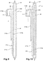
- the cuff 2 is manufactured in a conventional manner and has an inflatable pocket. It can be made in one piece ( figure 9 ) whose double wall 23, 24 defines the inflatable bag 25, and be made of an impermeable flexible plastic material such as a polymer or an elastomer, such as polyethylene or polyurethane. Preferably, it is made of a thermoplastic material.
- the cuff 2 can also be formed by two walls 23, 24 of non-impervious textile, such as cotton, which walls delimit a pocket in which the inflatable pocket 25 is housed ( figure 10 ), which bag is made of an impermeable flexible plastic material such as a polymer or an elastomer.
- An inflation means 3 makes it possible to inject air into the inflatable bag 25 of the cuff 2 in order to inflate it.
- this inflating means 3 is preferably in the form of an inflation bulb, which bulb is of the type usually used in the sphygmomanometer systems known from the prior art. It is sufficient for the doctor to exercise, by hand, successive pressures on the bulb 3 to inject air into the cord 4 and inflate the cuff.
- the bulb 3 is provided with a member 30 for controlling a valve or a valve for venting the inflatable bag 25 of the cuff 2. The actuation of this member 30 allows in particular to gradually reduce the pressure of the inflated cuff 2 for the determination of systolic pressures.
- This member 30 may be in the form of a wheel or a push button.
- the manometer 5 is of the known type and has a needle 50 cooperating with a graduation 52 of a reading dial, to indicate the arterial pressure.
- the tubular cord 4 is made of a flexible material, such as for example a polyethylene, a polystyrene, or any other plastic material suitable for the skilled person. It has a diameter ranging from 0.2 cm to 2 cm, and a length between 20 cm and 2 m.
- the figure 4 schematically a configuration where the pressure gauge 5 is associated with the inflation bulb 3 to form a mano-pear MP.
- This unique device MP is known to those skilled in the art.
- the mano-pear MP is connected to the cuff 2 by means of the tubular cord 4 allowing air to flow from the bulb 3 to the inside of the pocket of said cuff.
- the figure 6 schematically another configuration where the manometer 5 is directly associated with the cuff 2 to form a mano-cuff MB.
- the inflation bulb 3 is connected to the manometer 5 by the tubular cord 4. This configuration is known to those skilled in the art.
- connection means are adapted to make the configuration of the system 1 interchangeable.
- connection means consist of arrangements in the form of male endpieces and female orifices, of the quick assembly type.
- the tubular cord 4 comprises connection means 7 located on each of its ends 4a, 4b. These means of connection 7, connect the cord 4 to the various components of the system 1.
- the cord 4 has a male end 71 at each end 4a, 4b.
- These male end pieces 71 are adapted to fit into female complementary connection ports 6 described further in the description and which are located on the cuff 2, on the mano-pear MP, on the inflation bulb 3 and / or on the manometer 5.
- the connecting means 7 is formed of the outer male end 71 and an inner male end 72, these two ends being connected by a flange 75.
- this connection means 7 is advantageously manufactured from a alone.
- the end pieces 71, 72 and the flange 75 are made of a rigid material, such as for example a plastic material or a metal.
- the end pieces 71, 72 and the flange 75 are pierced axially so as to form a duct 70 allowing the circulation of air.
- the outer male end 71 is preferably in the form of a cylinder on which is installed a seal structure 73.
- This cylinder has for example an outer diameter of between 0.15 cm and 2 cm, and a length for example, may vary from 0.5 cm to 2 cm.
- a seal structure 73 is installed at the outer male end 71.
- at least one O-ring seal 73a, and preferably at least one three O-rings 73a, 73b, 73c are arranged around the cylinder of the nozzle 71. These O-rings 73a, 73b, 73c are spaced longitudinally, for example from a distance of 0.2 cm to 0.5 mm.
- the O-rings 73a, 73b, 73c are preferably made of rubber but they can also be made of another material, such as for example silicone.
- the outer male end 71 has several O-rings 73a, 73b, 73c, these can be made of identical materials or different materials.
- the seals 73a and 73b located at the proximal end (or inlet end) 71p of the tip 71 may be made of rubber and the seal 73c located at the distal end 71d may be realized silicone.
- the Applicant has found that such a configuration offers the best results in terms of airtightness.
- the inner male end piece 72 is preferably in the form of a cylinder similar to that forming the outer male element 71.
- This cylinder has for example a diameter between 0.15 cm and 2 cm, and a length for example, may vary from 0.5 cm to 2 cm.
- the inner male end piece 72 is adapted to fit tightly into the respective end 4a, 4b of the tubular cord 4 so that the connecting means 7 is secured to the latter.
- This internal male end piece 72 comprises at least one attachment collar 74 cooperating with the inner wall of the cord 4.
- This attachment collar 74 makes it possible to forcefully insert it into the tubular cord 4 and thus to ensure the tightness to the air between the connection means 7 and said cord.
- at least two collars 74, and preferably at least four attachment collars 74 are arranged around the cylinder of the nozzle 2.
- the external diameter of the collars 74 is slightly greater than the internal diameter of the cord 4 (by example of 1 mm) to ensure the insertion force of the inner male end 72 and a plastic deformation of the inner wall of the bead 4, which deformation provides airtightness.
- the flange 75 is disposed outside the bead 4 and bears against the respective end 4a, 4b of the latter.
- the flange 75 is presented by example in the form of a cylinder whose outer diameter corresponds to the outer diameter of the cord 4, its length being for example between 0.5 cm and 1 cm.
- the manometer 5 also has an external male end 51 identical to the tip 71 described above.
- This external male end 51 is located in the upper part of the pressure gauge, and projects from a lateral edge 500 of the dial, perpendicular to the Z axis of said dial.
- the female connection ports 6 are located on the cuff 2, on the mano-pear MP, on the inflation bulb 3 and on the manometer 5.
- the inlet of the female orifice 6 comprises a cylindrical sleeve-shaped liner 61 adapted to the seal structure 73. More particularly, this cylindrical sleeve 61 cooperates with the seal structure 73 to ensure an optimal airtightness between a male element 71 and the corresponding female connection port 6.
- the cylindrical sleeve 61 is made of a rigid material, such as a plastic material or a metal.
- the cylinder of the outer male ends 51, 71 has an outer diameter fitted to the inner diameter of the cylindrical sleeve 61.
- adjusted is meant that the inner diameter of the sleeve 61 is substantially equal to the outer diameter of the cylinder forming the outer male end. 51, 71, and preferably slightly greater (for example 0.5 mm) to prevent loosening of the seals 73 during the insertion of said tip 71.
- the sleeve 61 has for example an internal diameter of between 0.15 cm and 2 cm, and a length corresponding to that of the cylinder forming the outer male end 51, 71.
- the outer diameter of the sleeve 61 is such that it is inserted into force in the corresponding female orifice 6, thus ensuring a satisfactory airtightness between said orifice and said sleeve and an effective holding of the latter.
- An adhesive or glue may optionally be added between the inner surface of the orifice 6 and the outer surface of the sleeve 61 so as to further secure the holding in position.
- the figure 2 illustrates the case where the tubular cord 4 is directly connected to the cuff 2, this cord providing a direct connection between the mano-pear MP and said cuff ( figure 4 ).
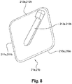
- the female orifice 6 of the cuff 2 is arranged in a protuberance 212a, 212b, said female orifice being in fluid communication with the inflatable bag of said cuff 2.
- the female orifice 6 opens into a conduit 60.
- This female orifice 6 may optionally be provided with the cylindrical liner sleeve 61 described above, or be devoid of this sleeve. In the latter case, the cylindrical inner wall of the female orifice 6 is directly adapted to the outer male end 51, 71, and more particularly to their joint structure.
- the inlet of the female orifice 6 is preferably arranged in such a way that its axis Y is parallel to the surface of the interface piece 21a, 21b, which axis Y is perpendicular to the longitudinal axis X of the cuff 2
- This orientation allows easier connection of the manometer 5 or the cord 4.
- the protuberance 212a, 212b is shaped protruding on an interface piece 21a, 21b, which interface piece acts as an interface between the inflatable bag 25 and the female orifice 6 of the cuff 2.
- the protuberance 212a, 212b is advantageously made of a rigid material, plastic or metal. It could, however, be made of a semi-rigid or flexible plastic material.
- the interface piece 21a, 21b has a rear face 210a, 210b in contact with the cuff 2 and a front face 211a, 211b on which the projection protrudes 212a, 212b.
- the figure 8 it has the shape of a rhombus whose sides have for example a length of between 2 cm and 10 cm. Its thickness can be between 1 mm and 20 mm.
- the figure 9 illustrates the case where the cuff 2 consists of a single piece whose double wall 23, 24 defines the inflatable bag 25.
- the protuberance 212a and the interface piece 21a form a single piece, obtained for example by molding or plastic injection.
- This one-piece piece is preferably made of a thermoplastic material, rigid or semi-rigid, so as to facilitate welding, but it can be made of another rigid material such as a plastic or a metal.
- the rear face 210a of the interface piece 21a is directly secured to one of the wall walls 23 of the cuff 2, for example by a welding process or by gluing.
- the conduit 60 opens at the rear face 210a of the interface piece 21a, which conduit is positioned opposite an opening 230 formed on the wall 23 so as to ensure fluid communication between the orifice 6 and the inflatable pocket 25.
- the figure 10 illustrates the case where the cuff 2 is formed by two non-impermeable walls 23, 24 delimiting a pocket in which is housed the impervious pocket 25 impervious.
- the protuberance 212b and the interface piece 21b can be two separate pieces.
- the protuberance 212b is preferably made of a thermoplastic material, rigid or semi-rigid, or in another rigid material such as a plastic or a metal.
- the interface piece 21b may be made of a flexible material such as a thermoplastic, or leather or a rigid material such as a plastic or a metal.
- the rear face 210b of the interface piece 21b is secured to one of the walls 23 of the cuff 2, for example by gluing or sewing.
- the protuberance 212b is secured to the front face 211b of the interface piece 21b, by example by gluing, sewing or riveting.
- the conduit 60 opens at the front face 211b of the interface piece 21b in which is arranged an opening, which opening is positioned vis-à-vis another opening made on the wall 23.
- the inflatable pocket 25 is provided with a tip 250 which passes through these two openings to be housed in the conduit 60. This provides a fluid communication between the orifice 6 and the pocket 25.
- a relief arrangement 213a, 213b in the form of a sole, is installed in front of the female orifice 6 and in the Y axis of the latter.
- This sole 213a, 213b allows to guide in position the outer end 71 of the cord 4 or the outer end 51 of the pressure gauge 5 ( figure 7 ).
- This sole 213a, 213b also makes it possible to stiffen and reinforce the interface piece 21a, 21b. Its length is for example between 1 cm and 5 cm, its width preferably corresponds to that of the protuberance 212a, 212b, and its thickness is for example between 2 mm and 1 cm.
- This sole 213a, 213b may have a concavity in the Y axis to facilitate the guide of the tip 71, 51.
- the sole 213a, 213b and the protuberance 212a, 212b may be made in a single piece or in two separate pieces. They can be an integral part of the interface part 21a, 21b and be made at the time of manufacture.
- the sole 213a, 213b can also be attached to the interface piece 21a, 21b subsequently by welding, gluing, riveting, or sewing.
- the material used for the sole 213a, 213b is preferably the same as that of the protuberance 212a, 212b. However, it can be made of another material such as plastic, metal, leather, etc.
- manometer 5 also has a female connection port 6.
- This orifice is located in the lower part of the manometer, to the opposite of the outer male end 51, said orifice and said tip being coaxial.
- the orifice 6 is arranged in the lateral edge 500 of the dial, perpendicularly to the Z axis of said dial.
- the inflation bulb 3 and the mano-pear MP also each comprise a female connection port 6.
- the doctor has at his disposal: the cuff 2, a single cord 4, the pressure gauge 5, the inflation bulb 3, and the mano-pear MP.
Landscapes
- Health & Medical Sciences (AREA)
- Life Sciences & Earth Sciences (AREA)
- Cardiology (AREA)
- Vascular Medicine (AREA)
- Biomedical Technology (AREA)
- Molecular Biology (AREA)
- Physiology (AREA)
- Biophysics (AREA)
- Pathology (AREA)
- Engineering & Computer Science (AREA)
- Veterinary Medicine (AREA)
- Heart & Thoracic Surgery (AREA)
- Medical Informatics (AREA)
- Physics & Mathematics (AREA)
- Surgery (AREA)
- Animal Behavior & Ethology (AREA)
- General Health & Medical Sciences (AREA)
- Public Health (AREA)
- Ophthalmology & Optometry (AREA)
- Dentistry (AREA)
- Measuring Pulse, Heart Rate, Blood Pressure Or Blood Flow (AREA)
Applications Claiming Priority (1)
| Application Number | Priority Date | Filing Date | Title |
|---|---|---|---|
| FR1654453A FR3051345B1 (fr) | 2016-05-19 | 2016-05-19 | Systeme de sphygmomanometre |
Publications (1)
| Publication Number | Publication Date |
|---|---|
| EP3248540A1 true EP3248540A1 (de) | 2017-11-29 |
Family
ID=57045048
Family Applications (1)
| Application Number | Title | Priority Date | Filing Date |
|---|---|---|---|
| EP17171886.9A Withdrawn EP3248540A1 (de) | 2016-05-19 | 2017-05-19 | Sphygmomanometer-system |
Country Status (2)
| Country | Link |
|---|---|
| EP (1) | EP3248540A1 (de) |
| FR (1) | FR3051345B1 (de) |
Families Citing this family (1)
| Publication number | Priority date | Publication date | Assignee | Title |
|---|---|---|---|---|
| JP7154932B2 (ja) * | 2018-10-15 | 2022-10-18 | オムロン株式会社 | 血圧測定装置 |
Citations (4)
| Publication number | Priority date | Publication date | Assignee | Title |
|---|---|---|---|---|
| US3906939A (en) * | 1972-11-10 | 1975-09-23 | Para Medical Instr Corp | Blood pressure measuring means |
| US6344025B1 (en) * | 1999-02-19 | 2002-02-05 | Omron Corporation | Blood pressure monitor |
| US20030114765A1 (en) * | 2001-12-19 | 2003-06-19 | Welch Allyn, Inc. | Blood pressure measuring apparatus |
| US20130331716A1 (en) * | 2000-09-25 | 2013-12-12 | Welch Allyn, Inc. | Blood pressure measuring apparatus |
-
2016
- 2016-05-19 FR FR1654453A patent/FR3051345B1/fr not_active Expired - Fee Related
-
2017
- 2017-05-19 EP EP17171886.9A patent/EP3248540A1/de not_active Withdrawn
Patent Citations (4)
| Publication number | Priority date | Publication date | Assignee | Title |
|---|---|---|---|---|
| US3906939A (en) * | 1972-11-10 | 1975-09-23 | Para Medical Instr Corp | Blood pressure measuring means |
| US6344025B1 (en) * | 1999-02-19 | 2002-02-05 | Omron Corporation | Blood pressure monitor |
| US20130331716A1 (en) * | 2000-09-25 | 2013-12-12 | Welch Allyn, Inc. | Blood pressure measuring apparatus |
| US20030114765A1 (en) * | 2001-12-19 | 2003-06-19 | Welch Allyn, Inc. | Blood pressure measuring apparatus |
Also Published As
| Publication number | Publication date |
|---|---|
| FR3051345B1 (fr) | 2018-09-28 |
| FR3051345A1 (fr) | 2017-11-24 |
Similar Documents
| Publication | Publication Date | Title |
|---|---|---|
| EP3856020B1 (de) | Verbindungssystem für ein sphygmomanometer | |
| CA2307735C (fr) | Catheter universel | |
| EP0731666B1 (de) | Vorrichtung zur messung der maximalströmung der ausatemluft | |
| EP2593154B1 (de) | Vorrichtung zur kontrolle eines in einem hämorrhagischen bereich erzeugten blutflusses | |
| FR2498454A1 (fr) | Catheter a membrane en forme de disque | |
| EP1581282B1 (de) | Vorrichtung zur medizinischen flüssigkeitsabgabe | |
| FR2579097A1 (fr) | Ensemble catheter exterieur et applicateur, et procede d'application d'un tel catheter sur le penis d'un patient | |
| CH618880A5 (de) | ||
| KR20080084863A (ko) | 혈압 측정 장치 | |
| FR2782646A1 (fr) | Appareil respiratoire comportant un ensemble indicateur | |
| FR2539300A1 (fr) | Dispositif et methode de formation d'un orifice dans la paroi d'une poche thermoplastique pour y inserer par exemple un catheter | |
| EP1720441B1 (de) | Druckübermittelnder verbinder für ein endoskopiesystem | |
| EP3248540A1 (de) | Sphygmomanometer-system | |
| FR3051347A1 (fr) | Systeme de connectique pour sphygmomanometre | |
| HUE029274T2 (en) | Disposable connector for haemofiltration | |
| FR2581188A1 (fr) | Indicateur de gonflage pour un tube medico-chirurgical a manchette. | |
| EP4178409B1 (de) | Ventil für ein medizinisches endoskop | |
| EP0646029A1 (de) | Kupplung für mehrlumigen schlauch | |
| FR3051343A1 (fr) | Brassard gonflable pour sphygmomanometre | |
| EP0360717B1 (de) | Katheter, der beim Anschluss drehbar ist | |
| FR2963226A1 (fr) | Outil de depistage d'une anomalie telle qu'une arteriopathie obliterante des membres inferieurs. | |
| CN223331185U (zh) | 一种三通单向阀 | |
| WO2015059367A1 (fr) | Dispositif pour poser une lentille de contact sur l'oeil | |
| FR3051346A1 (fr) | Methode de selection d'un brassard pour sphygmomanometre | |
| FR2886127A1 (fr) | Dispositif de mesure des capacites respiratoires d'un nourrisson |
Legal Events
| Date | Code | Title | Description |
|---|---|---|---|
| PUAI | Public reference made under article 153(3) epc to a published international application that has entered the european phase |
Free format text: ORIGINAL CODE: 0009012 |
|
| AK | Designated contracting states |
Kind code of ref document: A1 Designated state(s): AL AT BE BG CH CY CZ DE DK EE ES FI FR GB GR HR HU IE IS IT LI LT LU LV MC MK MT NL NO PL PT RO RS SE SI SK SM TR |
|
| AX | Request for extension of the european patent |
Extension state: BA ME |
|
| 17P | Request for examination filed |
Effective date: 20180515 |
|
| RBV | Designated contracting states (corrected) |
Designated state(s): AL AT BE BG CH CY CZ DE DK EE ES FI FR GB GR HR HU IE IS IT LI LT LU LV MC MK MT NL NO PL PT RO RS SE SI SK SM TR |
|
| GRAP | Despatch of communication of intention to grant a patent |
Free format text: ORIGINAL CODE: EPIDOSNIGR1 |
|
| INTG | Intention to grant announced |
Effective date: 20180720 |
|
| STAA | Information on the status of an ep patent application or granted ep patent |
Free format text: STATUS: THE APPLICATION IS DEEMED TO BE WITHDRAWN |
|
| 18D | Application deemed to be withdrawn |
Effective date: 20181201 |