EP3248544B1 - Dispositif et procédé pour mesurer la concentration d'une substance dans le sang - Google Patents
Dispositif et procédé pour mesurer la concentration d'une substance dans le sang Download PDFInfo
- Publication number
- EP3248544B1 EP3248544B1 EP16740127.2A EP16740127A EP3248544B1 EP 3248544 B1 EP3248544 B1 EP 3248544B1 EP 16740127 A EP16740127 A EP 16740127A EP 3248544 B1 EP3248544 B1 EP 3248544B1
- Authority
- EP
- European Patent Office
- Prior art keywords
- light
- substance
- laser light
- concentration
- laser
- Prior art date
- Legal status (The legal status is an assumption and is not a legal conclusion. Google has not performed a legal analysis and makes no representation as to the accuracy of the status listed.)
- Active
Links
Images






Classifications
-
- A—HUMAN NECESSITIES
- A61—MEDICAL OR VETERINARY SCIENCE; HYGIENE
- A61B—DIAGNOSIS; SURGERY; IDENTIFICATION
- A61B5/00—Measuring for diagnostic purposes; Identification of persons
- A61B5/145—Measuring characteristics of blood in vivo, e.g. gas concentration or pH-value ; Measuring characteristics of body fluids or tissues, e.g. interstitial fluid or cerebral tissue
- A61B5/1455—Measuring characteristics of blood in vivo, e.g. gas concentration or pH-value ; Measuring characteristics of body fluids or tissues, e.g. interstitial fluid or cerebral tissue using optical sensors, e.g. spectral photometrical oximeters
-
- A—HUMAN NECESSITIES
- A61—MEDICAL OR VETERINARY SCIENCE; HYGIENE
- A61B—DIAGNOSIS; SURGERY; IDENTIFICATION
- A61B5/00—Measuring for diagnostic purposes; Identification of persons
- A61B5/145—Measuring characteristics of blood in vivo, e.g. gas concentration or pH-value ; Measuring characteristics of body fluids or tissues, e.g. interstitial fluid or cerebral tissue
- A61B5/14532—Measuring characteristics of blood in vivo, e.g. gas concentration or pH-value ; Measuring characteristics of body fluids or tissues, e.g. interstitial fluid or cerebral tissue for measuring glucose, e.g. by tissue impedance measurement
-
- A—HUMAN NECESSITIES
- A61—MEDICAL OR VETERINARY SCIENCE; HYGIENE
- A61B—DIAGNOSIS; SURGERY; IDENTIFICATION
- A61B5/00—Measuring for diagnostic purposes; Identification of persons
- A61B5/145—Measuring characteristics of blood in vivo, e.g. gas concentration or pH-value ; Measuring characteristics of body fluids or tissues, e.g. interstitial fluid or cerebral tissue
- A61B5/14546—Measuring characteristics of blood in vivo, e.g. gas concentration or pH-value ; Measuring characteristics of body fluids or tissues, e.g. interstitial fluid or cerebral tissue for measuring analytes not otherwise provided for, e.g. ions, cytochromes
-
- G—PHYSICS
- G01—MEASURING; TESTING
- G01N—INVESTIGATING OR ANALYSING MATERIALS BY DETERMINING THEIR CHEMICAL OR PHYSICAL PROPERTIES
- G01N21/00—Investigating or analysing materials by the use of optical means, i.e. using sub-millimetre waves, infrared, visible or ultraviolet light
- G01N21/17—Systems in which incident light is modified in accordance with the properties of the material investigated
- G01N21/55—Specular reflectivity
-
- G—PHYSICS
- G02—OPTICS
- G02F—OPTICAL DEVICES OR ARRANGEMENTS FOR THE CONTROL OF LIGHT BY MODIFICATION OF THE OPTICAL PROPERTIES OF THE MEDIA OF THE ELEMENTS INVOLVED THEREIN; NON-LINEAR OPTICS; FREQUENCY-CHANGING OF LIGHT; OPTICAL LOGIC ELEMENTS; OPTICAL ANALOGUE/DIGITAL CONVERTERS
- G02F1/00—Devices or arrangements for the control of the intensity, colour, phase, polarisation or direction of light arriving from an independent light source, e.g. switching, gating or modulating; Non-linear optics
- G02F1/35—Non-linear optics
- G02F1/3501—Constructional details or arrangements of non-linear optical devices, e.g. shape of non-linear crystals
-
- G—PHYSICS
- G02—OPTICS
- G02F—OPTICAL DEVICES OR ARRANGEMENTS FOR THE CONTROL OF LIGHT BY MODIFICATION OF THE OPTICAL PROPERTIES OF THE MEDIA OF THE ELEMENTS INVOLVED THEREIN; NON-LINEAR OPTICS; FREQUENCY-CHANGING OF LIGHT; OPTICAL LOGIC ELEMENTS; OPTICAL ANALOGUE/DIGITAL CONVERTERS
- G02F1/00—Devices or arrangements for the control of the intensity, colour, phase, polarisation or direction of light arriving from an independent light source, e.g. switching, gating or modulating; Non-linear optics
- G02F1/35—Non-linear optics
- G02F1/39—Non-linear optics for parametric generation or amplification of light, infrared or ultraviolet waves
-
- A—HUMAN NECESSITIES
- A61—MEDICAL OR VETERINARY SCIENCE; HYGIENE
- A61B—DIAGNOSIS; SURGERY; IDENTIFICATION
- A61B90/00—Instruments, implements or accessories specially adapted for surgery or diagnosis and not covered by any of the groups A61B1/00 - A61B50/00, e.g. for luxation treatment or for protecting wound edges
- A61B90/30—Devices for illuminating a surgical field, the devices having an interrelation with other surgical devices or with a surgical procedure
- A61B2090/306—Devices for illuminating a surgical field, the devices having an interrelation with other surgical devices or with a surgical procedure using optical fibres
-
- A—HUMAN NECESSITIES
- A61—MEDICAL OR VETERINARY SCIENCE; HYGIENE
- A61B—DIAGNOSIS; SURGERY; IDENTIFICATION
- A61B90/00—Instruments, implements or accessories specially adapted for surgery or diagnosis and not covered by any of the groups A61B1/00 - A61B50/00, e.g. for luxation treatment or for protecting wound edges
- A61B90/36—Image-producing devices or illumination devices not otherwise provided for
- A61B90/361—Image-producing devices, e.g. surgical cameras
- A61B2090/3614—Image-producing devices, e.g. surgical cameras using optical fibre
-
- A—HUMAN NECESSITIES
- A61—MEDICAL OR VETERINARY SCIENCE; HYGIENE
- A61B—DIAGNOSIS; SURGERY; IDENTIFICATION
- A61B2562/00—Details of sensors; Constructional details of sensor housings or probes; Accessories for sensors
- A61B2562/02—Details of sensors specially adapted for in-vivo measurements
- A61B2562/0233—Special features of optical sensors or probes classified in A61B5/00
-
- G—PHYSICS
- G02—OPTICS
- G02F—OPTICAL DEVICES OR ARRANGEMENTS FOR THE CONTROL OF LIGHT BY MODIFICATION OF THE OPTICAL PROPERTIES OF THE MEDIA OF THE ELEMENTS INVOLVED THEREIN; NON-LINEAR OPTICS; FREQUENCY-CHANGING OF LIGHT; OPTICAL LOGIC ELEMENTS; OPTICAL ANALOGUE/DIGITAL CONVERTERS
- G02F1/00—Devices or arrangements for the control of the intensity, colour, phase, polarisation or direction of light arriving from an independent light source, e.g. switching, gating or modulating; Non-linear optics
- G02F1/35—Non-linear optics
- G02F1/3501—Constructional details or arrangements of non-linear optical devices, e.g. shape of non-linear crystals
- G02F1/3507—Arrangements comprising two or more nonlinear optical devices
-
- H—ELECTRICITY
- H01—ELECTRIC ELEMENTS
- H01S—DEVICES USING THE PROCESS OF LIGHT AMPLIFICATION BY STIMULATED EMISSION OF RADIATION [LASER] TO AMPLIFY OR GENERATE LIGHT; DEVICES USING STIMULATED EMISSION OF ELECTROMAGNETIC RADIATION IN WAVE RANGES OTHER THAN OPTICAL
- H01S3/00—Lasers, i.e. devices using stimulated emission of electromagnetic radiation in the infrared, visible or ultraviolet wave range
- H01S3/14—Lasers, i.e. devices using stimulated emission of electromagnetic radiation in the infrared, visible or ultraviolet wave range characterised by the material used as the active medium
- H01S3/16—Solid materials
- H01S3/1601—Solid materials characterised by an active (lasing) ion
- H01S3/1603—Solid materials characterised by an active (lasing) ion rare earth
-
- H—ELECTRICITY
- H01—ELECTRIC ELEMENTS
- H01S—DEVICES USING THE PROCESS OF LIGHT AMPLIFICATION BY STIMULATED EMISSION OF RADIATION [LASER] TO AMPLIFY OR GENERATE LIGHT; DEVICES USING STIMULATED EMISSION OF ELECTROMAGNETIC RADIATION IN WAVE RANGES OTHER THAN OPTICAL
- H01S3/00—Lasers, i.e. devices using stimulated emission of electromagnetic radiation in the infrared, visible or ultraviolet wave range
- H01S3/14—Lasers, i.e. devices using stimulated emission of electromagnetic radiation in the infrared, visible or ultraviolet wave range characterised by the material used as the active medium
- H01S3/16—Solid materials
- H01S3/163—Solid materials characterised by a crystal matrix
- H01S3/164—Solid materials characterised by a crystal matrix garnet
- H01S3/1643—YAG
-
- H—ELECTRICITY
- H01—ELECTRIC ELEMENTS
- H01S—DEVICES USING THE PROCESS OF LIGHT AMPLIFICATION BY STIMULATED EMISSION OF RADIATION [LASER] TO AMPLIFY OR GENERATE LIGHT; DEVICES USING STIMULATED EMISSION OF ELECTROMAGNETIC RADIATION IN WAVE RANGES OTHER THAN OPTICAL
- H01S3/00—Lasers, i.e. devices using stimulated emission of electromagnetic radiation in the infrared, visible or ultraviolet wave range
- H01S3/14—Lasers, i.e. devices using stimulated emission of electromagnetic radiation in the infrared, visible or ultraviolet wave range characterised by the material used as the active medium
- H01S3/22—Gases
- H01S3/223—Gases the active gas being polyatomic, i.e. containing two or more atoms
- H01S3/2232—Carbon dioxide (CO2) or monoxide [CO]
Definitions
- the present invention relates to a device for measuring the concentration of a substance in blood and measures a substance (glucose, lipids, and the like) in blood non-invasively, and relates to a method for measuring the concentration of a substance in blood.
- a micro-invasive type blood glucose meter capable of continuously measuring the blood glucose level by a method of applying a patch with a needle-type sensor attached to the back side (Continuous Glucose Monitoring (CGM): continuous type subcutaneous blood glucose measurement system) is being sold in the USA and in Japan.
- CGM Continuous Glucose Monitoring
- a patch type sensor was approved in the fall of 2009 as a medical device by the Ministry of Health, Labor and Welfare, and in February 2010, this patch type sensor became applicable to insurance.
- this patch type sensor is still invasive in that the needle-type sensor is kept in a state of being stuck under the skin and burdens the patient with annoyance and stress.
- the glucose concentration in the interstitial fluid (epithelial interstitial fluid) right under the epidermis is measured.
- the blood glucose level changes over time
- there is a time difference in the change over time of the glucose concentration and blood glucose level in the interstitial fluid since there is a strong relationship between them, it is actually possible to recognize the glucose concentration in the interstitial fluid as the blood glucose level.
- non-invasive methods such problems do not occur because stress to the patient is small, and these methods are preferably used for daily management of the blood glucose level.
- non-invasive methods when compared with invasive methods in which the glucose concentration in the blood is measured directly, are limited as methods for detecting glucose, so at present the measurement accuracy is inferior in comparison with invasive methods. Therefore, attempts are being made to develop a non-invasive blood glucose level measuring method that is capable of measuring the blood glucose level with the same accuracy as invasive methods.
- the blood glucose concentration is measured by absorption in blood of light that is transmitted though the skin.
- laser light is used, and the laser light is locally irradiated onto the body using optical fiber or the like, and the absorption of the light by glucose in the blood is measured by measuring the intensity of transmitted light or scattered light from the body.
- the laser light that is used here must be such that, in addition to being able to measure the absorption by glucose, the light must be able to reach inside the body, and as this laser light, light in the near infrared region (wavelength of about 1 to 2 ⁇ m) of which there is little absorption by the skin and the like is widely used.
- Near-infrared light is such that little of the light is absorbed by hemoglobin and water, so the light easily reaches the inside of the body, and the change in the intensity of the laser light due to absorption near the wavelength of 1.5 ⁇ m in the glucose absorption spectrum is measured. Therefore, it is possible to measure the glucose concentration in the blood by detecting the intensity of light after being transmitted through blood in the body, and comparing that intensity with the intensity of the incident light.
- near infrared light is irradiated onto the subcutaneous tissue (dermal tissue) under a nail via optical fiber for irradiation, then diffused reflected light from the subcutaneous tissue is guided to light receiving means by optical fiber for receiving light and measurement of the absorption spectrum is performed.
- the blood glucose level is calculated from the measurement results (the blood glucose level is estimated by measuring the glucose concentration in the dermal tissue as a substitute property of the blood glucose level).
- the blood glucose level is calculated by using a database of a large number of measurement data, variables related to bodies, and measurement results by an invasive method, and substituting in measurement values of the spectrum into a calibration formula that is obtained by multivariate analysis.
- Non-patent document 1 being able to measure the blood glucose level by non-invasive methods by recognizing the absorption peak by glucose from an FTIR absorption spectrum after trans-membrane penetration of blackbody radiated light with a wide spectrum in the mid-infrared region from a nichrome wire heater, without using monochromatic light such as described above is described in Non-patent document 1. Furthermore, a method for measuring blood glucose using blackbody radiated light in the mid-infrared region from body heat is proposed in Patent Document 3.
- Patent Document 4 it is also possible to measure the glucose concentration in the interstitial fluid (epithelial interstitial fluid) just below the epidermis instead of blood deep inside the body.
- the glucose concentration in this epithelial interstitial fluid is calculated from the infrared light absorption spectrum using plural laser light sources.
- technology is described in Non-patent Document 2 in which the glucose concentration is estimated by performing mulitvariate analysis by performing a wavelength sweep of a specific wavelength region using a quantum cascade laser in the mid-infrared region, and measuring the change in the photoacoustic signal that is due to a change in the glucose concentration in the epithelial interstitial fluid.
- the near infrared light that is used in Patent Documents 1 and 2 easily reaches to the capillaries of the epithelium of the body, the rate of change in the light intensity due to absorption by glucose of near-infrared light (for example, at a wavelength of 1.5 ⁇ m) is only about 0.4%. Therefore, the light intensity that is detected it greatly affected by various substances (proteins, lipids and the like) in the blood other than glucose. Moreover, absorption that is due to such substances other than glucose is greatly affected by environmental conditions (body temperature and the like), so the uncertainty of the absorption increases. Consequently, the measurement error of the glucose concentration is as large as about 20 to 30 mg/dL, and that is very inferior when compared with that in the case of invasive methods.
- Non-patent Documents 1 and 2 and Patent Documents 3 and 4 infrared light having a wavelength longer than these is used, so the effect on absorption due to glucose can be made to be sufficiently larger than the effect on absorption due to biological components other than glucose.
- the transmittance of light in the body is low, so the intensity of light that is detected is low.
- the peak power (peak power) per single wavelength that is obtained from the light source that is used in this wavelength range is typically very low when compared with the case of near-infrared light, and the intensity of background light in this wavelength range is high, so it is difficult to obtain sufficient S/N that is necessary for measuring the blood glucose level.
- a measurement device having a complicated configuration that uses plural laser light sources such as in the technology described in Patent Document 4, and furthermore, as in the technology described in Non-patent Document 2, a complex analysis method such as multivariate analysis or the like that measures the change in a photoacoustic signal due to change in the glucose concentration in the epithelial interstitial fluid becomes necessary, or the measurement device or analysis device becomes large and complicated, and, for example, is not suited to measuring the change over time of the blood glucose level.
- an object of the present invention is to provide an invention that solves the problems above.
- the present invention is configured as described below.
- a device for measuring the concentration of substance in blood that measures the concentration of substance that is included in the blood of a body, including: a laser oscillator that oscillates a first laser light having a specific wavelength and that is absorbed by the substance; a light-guiding unit that guides the first laser light to the body, and guides first diffused reflected light that is generated by the first laser light from the body; and a light-detection unit that detects the light intensity of the first diffused reflected light, wherein: the specific wavelength of the first laser light is selected from the range 2.5 ⁇ m to 12 ⁇ m; in the light-guiding unit, an incident-side optical waveguide that guides the first laser light to the body and an exit-side optical waveguide that guides the first diffused reflected light to the light-detection unit are each formed as a through hole so as to penetrate through the same light-guiding unit; and the first laser light is collected by the incident side optical waveguide which is formed as a through hole, a window is provided to the light-
- the light-guiding unit guides the first laser light to the body at an incident angle of 35° to 85°.
- the light-guiding unit guides the first laser light to the body at an incident angle of 60° to 70°.
- the laser oscillator is an optical parametric oscillator that uses excitation light having a wavelength that is different than the first laser light and that is emitted from an excitation light source, and that oscillates the first laser light by first non-linear optical crystal.
- the excitation-light source is a passive Q-switched Nd:YAG laser or passive Q-switched Yb:YAG laser.
- the excitation-light source oscillates a pulsed excitation light with a repetition frequency of 1 Hz or greater.
- the laser oscillator is a carbon dioxide gas laser oscillator.
- the laser oscillator oscillates a second laser light having a wavelength that is within the range 2.5 to 12 ⁇ m and that is different than that of the first laser light, and that has a characteristic of being absorbed by the substance less than the first laser light; and in the light-guiding unit the incident-side optical waveguide guides the second laser light to the body, and the exit-side optical waveguide guides second diffused reflected light that is generated by the second laser light to the light-detection unit.
- the optical parametric oscillator includes a second non-linear optical crystal that generates the second laser light using the excitation light.
- the first non-linear optical crystal and the second non-linear optical crystal are arranged in series on the optical path.
- the laser oscillator oscillates a second laser light having a wavelength within the range 2.5 to 12 ⁇ m and that is different than that of the first laser light, and that has a characteristic of being absorbed by the substance less than the first laser light; and in the light-guiding unit, the incident-side optical waveguide guides the second laser light to the body, and the exit-side optical waveguide guides second diffused reflected light that is generated by the second laser light to the light-detection unit.
- the laser oscillator oscillates the first laser light and the second laser light in a pulsed shape with a repetition frequency of 1 Hz or greater.
- a concave section or an convex section that is provided in the light-guiding unit at a location which is to be brought closer to the body, the concave section or the convex section being provided so that a space is formed between the body and the light-guiding unit at and around a location at which the body is irradiated with the first laser light when the concentration of substance is measured.
- the device for measuring the concentration of substance in blood of the present invention further includes a window that is made using a material that allows the first laser light to pass through, and that has a shape so that when inserted between the light-guiding unit and the body, a space is formed between the window and the body through which the first laser light and the first diffused reflected light pass.
- the substance is glucose; and the wavelength of the first laser light is within the range 7.0 ⁇ m to 11 ⁇ m.
- the incident side optical waveguide is formed such that an exit side of the incident side optical waveguide gradually becomes narrower than an incident side of the incident side optical waveguide.
- a method for measuring the concentration of substance in blood that measures the concentration of substance included in blood of a body, and measures the concentration of substance in epithelial interstitial fluid of the body by light intensity of first diffused reflected light that is generated by irradiating the body with a first laser light having a specific wavelength and that is absorbed by the substance, wherein the first laser light is guided to the body via an incident-side optical waveguide, the first diffused reflected light is guided to a light-detection unit via an exit-side optical waveguide, the light-detection unit detecting the light intensity, wherein the specific wavelength of the first laser light is selected from the range 2.5 ⁇ m to 12 ⁇ m; the incident-side optical waveguide and the exit-side optical waveguide are each formed as a through hole so as to penetrate through the same light-guiding unit; and the first laser light is collected by the incident side optical waveguide which is formed as a through hole, wherein providing a window to the light-guiding unit at a
- the method for measuring the concentration of substance in blood that guides the first laser light to the body at an incident angle of 35° to 85°, and more preferably 60° to 70°.
- the method for measuring the concentration of substance in blood that oscillates the first laser light by optical parametric oscillation.
- the method for measuring the concentration of substance in blood that oscillates the first laser light by a carbon dioxide gas laser oscillator.
- the method for measuring the concentration of substance in blood that measures the concentration of the substance in epithelial interstitial fluid of the body by the light intensity of the first diffused reflected light and the light intensity of second diffused reflected light that is generated by the second laser light
- the optical path of the first laser light and the optical path of the second laser light overlap, and the optical path of the first diffused reflected light that is incident on a light-detection unit that detects the light intensity, and the optical path of the second diffused reflected light that is incident on the light-detection unit overlap.
- the substance is glucose
- the wavelength of the first laser light is within the range 7.0 ⁇ m to 11 ⁇ m.
- the present invention is configured as described above, so it is possible to measure the concentration of substance in blood non-invasively, with high accuracy and with simple configuration.
- FIG. 1 illustrates the configuration of this blood glucose meter 1.
- This blood glucose meter 1 is a non-invasive type, and locally irradiates laser light (first laser light) 100 that is generated by a light source 10 onto the epithelium of the body (body) F of a test subject, and the diffused reflected light (first diffused reflected light) 200 thereof is detected by a light detector (light detection unit) 40.
- the substance that is included in the blood that is the object to be measured is glucose.
- the laser light 100 that is used here is mid-infrared light, the wavelength, for example, is 9.26 ⁇ m, and the light is oscillated by a light source 10.
- laser light 100 is generated by converting an excitation light 101 having a wavelength that is shorter than the pulse-like mid-infrared light that is oscillated from an excitation light source 11 to a long wavelength while at the same time amplifying the light by an OPO (optical parametric oscillator) 12.
- This optical parametric oscillation is described, for example, in JP2010281891 (A ).
- the wavelength oscillated by optical parametric oscillation is taken to be 9.26 ⁇ m.
- This wavelength is set as a wavelength with large absorption by glucose.
- This wavelength for example, can be set according to a spectrum of a fluid that includes glucose as described in Non-patent Document 1 above.
- a Q-switched ND:YAG laser (oscillation wavelength of 1.064 ⁇ m) or a Q-switched Yb:YAG laser (oscillation wavelength of 1.030 ⁇ m) capable of generating a pulse-like excitation light 101 having a wavelength that is shorter than mid-infrared light be used.
- a passive Q-switched Nd:YAG laser or Yb:YAG laser that is capable of automatically performing a switching operation using a supersaturated absorber is able to simplify and miniaturize the excitation light source 11 and the configuration for controlling the excitation light source 11, so is particularly preferred.
- Q-switched oscillation it is possible, for example, to oscillate an excitation light 101 with a repetition of 10 Hz or greater and pulse width of about 8 ns.
- FIG. 2 schematically illustrates the configuration of the OPO 12.
- a non-linear optical crystal 123 is placed between an incident side half mirror 121 and an exit side half mirror 122.
- the excitation light 101 that passes through the incident side half mirror 121 enters on the non-linear optical crystal 123, and is converted to light having a wavelength of 9.26 ⁇ m that is the wavelength set by the non-linear optical crystal 123, and when the light is reflected and confined between the incident side half mirror 121 and exit side half mirror 122, the light is amplified by optically parametric amplification.
- the amplified light passes through the exit side half mirror 122, becomes laser light 100 and is outputted.
- FIG. 1 schematically illustrates the configuration of the OPO 12.
- the direction of the laser light 100 that is emitted from the OPO 12 and the direction of the excitation light 101 are illustrated as being different, however, the directions are appropriately adjusted using a suitable reflector.
- the non-linear optical crystal 123 AgGaS that is suitable for this kind of wavelength conversion is used under the condition of phase matching. By adjusting the type and matching conditions of the non-linear optical crystal 123, it is possible to adjust the wavelength of the emitted laser light 100.
- the non-linear optical crystal it is also possible to use GaSe, ZnGeP 2 , CdSiP 2 , LilnS 2 , LiGaSe 2 , LilnSe 2 , LiGaTe 2 and the like.
- the laser light 100 that is emitted from the OPO 12 has a repetition frequency and a pulse width (for example, about 8 ns) that corresponds to the excitation light 101, and with this short pulse width, the peak output has a high intensity of 10 W to 1 kW.
- the laser light 100 is collected by the condenser lens 14 after the path is adjusted by the mirror 13, then enters into the incident side optical waveguide 21 that is provided in a light-guiding unit 20.
- a beam splitter 15 that is configured with a half mirror provided between the mirror 13 and condenser lens 14, and part of the laser light 100 is branched off to be used for a monitor.
- the part of the laser light 100 that is branched off is detected by a monitoring light detector (monitoring light detector unit) 16, so even when there is fluctuation in the intensity of the laser light 100 itself, that fluctuation can be recognized from the output of the monitoring light detector 16.
- a mostly flat plate shaped window 30 that is made using a material that is transparent to mid-infrared light is provided between the light-guiding unit 20 and the body epithelium F, and the window 30 and body epithelium F come in close contact.
- Laser light 100 that passes through the window 30 is incident on the body epithelium F.
- the angle of incidence of the laser light 100 with respect to the body epithelium F is determined by the angle of the incident side optical waveguide 21 with respect to the bottom surface of the light-guiding unit 20 (top surface of the window 30) and the refraction angle of the laser light 100 that is incident on the window 30 at this angle.
- the laser light 100 is incident on the body epithelium F and passes through the epithelial stromal tissue of the body, and the scattered or diffused reflected light 200 passes though the window 30 again, then passes through the exit side optical waveguide 22 that is formed in the light-guiding unit 20 and is obtained on the outside of the light-guiding unit 20.
- the direction from which the diffused reflected light 200 is obtained is set by the angle of the exit-side optical waveguide 22 with respect to the bottom surface of the light-guiding unit 20 (top surface of the window 30), and this angle is the same as that of the incident-side optical waveguide 21 described above.
- This diffused reflected light 200 is detected by a light detector 40 that detects mid-infrared light and outputs that light as an electrical signal.
- the light-guiding unit 20 is made using a metal material such as stainless steel or the like, and inside the light-guiding unit 20, an incident side optical waveguide 21 and an exit side optical waveguide 22 are formed as through holes.
- the inside surfaces of the incident side optical waveguide 21 and exit side optical waveguide 22 are coated in order to increase the light reflectance. It is possible to use a multilayer dielectric film as the coating material for increasing the light reflectance.
- the incident side optical waveguide 21 is formed such that the exit side thereof gradually becomes narrower than the incident side. As a result, it is possible to collect light by the incident side optical waveguide 21 as well, and it is possible to limit the irradiation range of the irradiated laser light 100.
- the window 30 is made using a material such as ZnSe or the like that is transparent to mid-infrared light, and the surface of the window 30 is coated with a non-reflective coating.
- FIG. 3 illustrates the positional relationship of the light-guiding unit 20, the window 30 and the body epithelium F as seen from the left side (incident side) in FIG. 1 .
- the refractive index of ZnSe with respect to mid-infrared light is about 2.4
- the refraction angle of the laser light 100 in the window 30 is determined by the refractive index.
- a slit 30A that is a concave section is provided on the bottom surface side in FIG. 3 of the window 30 so that when the window 30 is brought into close contact with a finger, a gap having a width D is formed between the window 30 and the body epithelium F at the areas around the outlet of the incident side optical waveguide 21 and the inlet of the exit side optical waveguide 22 of the light-guiding unit 20.
- a slit 30A that is a concave section is provided on the bottom surface side in FIG. 3 of the window 30 so that when the window 30 is brought into close contact with a finger, a gap having a width D is formed between the window 30 and the body epithelium F at the areas around the outlet of the incident side optical waveguide 21 and the inlet of the exit side optical waveguide 22 of the light-guiding unit 20.
- the refractive index of the ZnSe of the window 30 is large, so at the interface between the window 30 and the body epithelium F, it is easy for the laser light 100 to be totally reflected, and particularly, the state of this total reflection is greatly influenced by the condition of close contact between the window 30 and the body epithelium F, however, by stabilizing this state with the slit 30A and by providing this kind of space between the window 30 and the body epithelium F, it is possible to stably maintain a state in which total reflection is suppressed.
- the thickness of the window 30 is set, for example, to be 500 ⁇ m, the width of the slit 3A is 700 ⁇ m, and the space D is about 400 ⁇ m.
- the body epithelium F is soft so there is close contact between the body epithelium F and the window 30 at locations other than where the slit 30A is provided.
- FIG. 3 it is possible for configuration to be such that a slit 30A is not provided and the bottom surface side of the window 30 is a flat shape, and to essentially form a slit 30A by applying tape or the like to the outer sides of the portion that corresponds to the slit 30A to form convex shapes on the bottom side of this portion.
- an HgCdTe infrared detector that is cooled with liquid nitrogen is used for example.
- the light detector 40 detects diffused reflected light 200 having an intensity that is high enough that background light can be ignored.
- the light detector 40 by cooling with liquid nitrogen to about 77K, it is possible to detect the light intensity of diffused reflected light 200 with a high S/N ratio.
- accurate analysis as will be described later becomes possible by using the output (detected intensity) of the light detector 40 that is normalized by the output (detected intensity) of the monitoring light detector 16.
- near-infrared light having transmittance into the body is mainly used as monochromatic light used for analysis.
- mid-infrared light (laser light 100) having low transmittance into the body is used as the light used for analysis. Therefore, only the epidermis portion is observed, and observation is not easily affected by other biological components that are present in deeper portions. Moreover, as described above, there is little adverse effect on measurement due to overlapping of harmonics and coupled sound of reference vibration.
- an excitation light source 11 and OPO 12 it is possible to increase the intensity of the laser light 100 that enters into the body epithelium F, it is possible to obtain a laser light 100 having a high intensity that is about 10 3 to 10 5 times higher when compared with a typical light source of infrared light having a wavelength of 9.26 ⁇ m (for example, a quantum cascade laser). Therefore, the intensity of the diffused reflected light 200 that is detected by the light detector 40 can be made to be sufficiently higher than the background light, and when compared with typical technology that uses infrared light in the same wavelength range (Patent Documents 3 and 4, Non-patent documents 1 and 2 and the like), it is possible to perform measurement with much higher accuracy.
- the laser light 100 and the diffused reflected light 200 are monochromatic and have high intensity, so it is possible to calculate the glucose concentration in the interstitial fluid by using the normalized light intensity that is calculated from the signal ratio of the monitoring light detector 16 and light detector 40, it is possible to make a 1-to-1 correlation with this and the glucose concentration in blood, and it is not necessary to perform spectrum analysis, multivariate analysis or the like. Furthermore, there is no need to take time for a wavelength sweep as in the photoacoustic optical method that uses a quantum cascade laser, so measurement can be performed in a short period of time.
- FIG. 4 illustrates the results when, after orally ingesting an aqueous solution in which 37g of glucose is dissolved in approximately 200 ml of water, the blood glucose level is measured using an invasive blood glucose level measurement method on the same body, and the results when correspondence between the signal ratio of the light detector 40 and the monitoring light detector 16 in the configuration described above (normalized light intensity) is measured for different blood glucose levels.
- a Q-switched ND:YAG laser is used as the excitation light source 11.
- (a) in FIG. 4 illustrates the results when the configuration in FIGS. 1 and 3 is used
- (b) in FIG. 4 illustrates the results when laser light 100 having the same angle of incidence directly enters into the body epithelium F.
- the number of irradiations of the laser light 100 is 256 shots per time, and the measurement time is approximately 30 seconds.
- the normalized light intensity decreases as the blood glucose level increases. This is caused by laser light 100 having a wavelength of 9.26 ⁇ m being absorbed by glucose in the epithelial interstitial fluid.
- this variation decreases to a level that can be ignored in the figure (about ⁇ 2%). Therefore, particularly in the case of (a) there is a 1-to-1 correspondence between the light intensity that is measured by the light detector 40 and the true blood glucose level, and it is possible to find the true blood glucose level on a 1-to-1 basis from just the light intensity that is measured by the light detector 40. Consequently, complicated statistical analysis and the like is not needed, and with the simple device configuration illustrated in FIG. 1 , it is possible to measure the glucose concentration in blood (blood glucose level).
- a Q-switched Nd:YAG laser that is able to emit a pulse-like excitation light having a wavelength of 1.064 ⁇ m at a repetition of 100 Hz is used as the excitation light source 11, and the blood glucose levels for plural test subjects was measured.
- the number of irradiations of laser light is 256 shots per time, however, the repetition number of laser is 100 Hz, so the measurement time is greatly shortened to about 3 seconds.
- an electron-cooled HgCdTe detector that does not require liquid-nitrogen cooling having, however has an inferior S/N ratio when compared with the case of a liquid-nitrogen cooling is used as the light detector 40 and the monitoring light detector 16.
- the other configuration is the same as in the example described above.
- FIG. 5 illustrates the correlation of the result of measuring the blood glucose level at this time using a blood collection type blood glucose level measurement method, and signal ratio (normalized light intensity) of the monitoring light detector 16 and light detector 40 of the configuration described above that is measured for different blood glucose levels.
- the normalized light intensity decreases as the blood glucose level increases.
- the accuracy of the error by comparison with the invasive blood glucose level measurement method is ⁇ 9% (bottom) and ⁇ 6% (top) for test subject A, and ⁇ 5.5%, ⁇ 12.5% and ⁇ 19.5% for test subjects B, C and D, respectively. These values all satisfy the ISO standard for measurement accuracy of ⁇ 20% or less, and data that is comparable to that of commercially available invasive blood glucose level measurement devices is obtained.
- the glucose level can be measured easily and in a much shorter time than with an invasive blood glucose level measurement device, making it possible to greatly reduce a patient's stress.
- the repetition frequency of laser light 100 is high, and a frequency of 1 Hz or greater is preferred.
- the light intensity of the diffused reflected light 200 (wavelength ⁇ 1 ) is also affected by factors other than glucose such as the absorption of incident light by the skin, or components other than glucose in the interstitial fluid.
- the wavelength By setting the wavelength to ⁇ 1 at which the absorption due to glucose is especially large, it is possible to reduce the effect of absorption due to factors other then glucose.
- the characteristics in FIG. 4 beforehand for the same subject when the effect of absorption due to factors other than glucose does not fluctuate over time, the fluctuation over time of the blood glucose level can be accurately calculated.
- the characteristics in FIG. 4 according to race, gender, age and the like even when the test subjects are not the same, it is possible to increase the accuracy of measuring the blood glucose level.
- the OGTT described above was performed on four healthy persons (A to D) multiple times on different days, and the blood glucose level was measured using an invasive method (blood sampling), while at the same time, using the normalized light intensity that is obtained by the method described above, the blood glucose level was calculated from the approximation straight line in FIG. 5 .
- a comparison of the blood glucose level obtained by blood sampling and the blood glucose level obtained by the method described above (non-invasive method) was performed for much data, and the results are shown in FIG. 6 .
- the blood glucose value sensor is used for medical practice, and in this case, the allowed measurement tolerance differs according to the absolute value of the actual blood glucose value. In other words, when the absolute value of the blood glucose value is small (when the subject is recognized as being healthy), and when the absolute value of the blood glucose value is large (when treatment is necessary), the allowable measurement tolerance differs.
- Clarke error grid analysis typically for the blood glucose value sensor evaluation, Clarke error grid analysis that mainly focuses on the effect that the tolerance of the measurement results have on the appropriateness of the medical treatment for a patient is used ( Clarke WL, Cox D, Gonder-Frederick LA, Carter W, Pohl SL, "Evaluating Clinical Accuracy of Systems for Self-Monitoring of Blood Glucose", Diabetes Care, Vol. 10, p 622 to 628 (1987 )).
- Clarke error grid analysis a correlation diagram as illustrated in FIG. 6 is such that the range recognized as being accurate measurement is set as zone A (the most preferred range).
- Zone A is within ⁇ 15 mg/dl when the blood glucose value is less than 75 mg/dl, and is within ⁇ 20% when the blood glucose value is equal to or greater than 75 mg/dl. From the results in FIG. 6 , a large portion of the measurement points (95% or greater) are inside zone A, and all of the measurement points other than that also exist very close to the boundary of zone A. In other words, by using the normalized light intensity as described above, it is possible to measure the blood glucose level with clinically sufficient accuracy.
- a monitoring light detector 16 is used together with a light detector 40, and the blood glucose level is calculated using the normalized light intensity of the diffused reflected light 200, however, when the stability of the laser light 100 is high, or when it is possible to monitor fluctuation of the laser light 100 by using another method, the monitoring light detector 16 and the beam splitter 15 are not necessary. In that case, instead of the normalized light intensity, it is possible to use the detection intensity (output) of the light detector 40. Alternatively, it is possible to calculate a correction factor according to the fluctuation of the laser light 100 that is monitored by another method, and use that correction factor instead of the light intensity that is detected by the monitoring light detector 16.
- the wavelength of the laser light 100 is set to 9.26 ⁇ m at which a large amount of absorption due to glucose is observed. In this way, it is possible to use a laser light 100 (first laser light) having wavelength ⁇ 1 for which the absorption due to glucose is large together with a laser light 100 (second laser light) having a wavelength ⁇ 2 for which there is hardly any effect of absorption due to glucose. In other words, it is possible to use laser light having two wavelengths as the laser light 100.
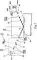
- FIG. 7 The configuration of a blood glucose meter 2 for the case in which two wavelengths are used in this way is illustrated in FIG. 7 that is correlated with FIG. 1 .
- a light-guiding unit 20 and window that are used in the blood glucose meter 1 are used in the same way.
- the light source 50 that is used here and the configuration for detecting the light intensity of the diffused reflected light are different.
- an excitation light source 11, mirror 13, condenser lens 14 and beam splitter 15 are used in the same way
- the monitoring light detector 16 is also used in the same way.
- FIG. 8 is a figure that correlates the configuration of the OPO 52 that is used here with FIG. 2 .
- a non-linear optical crystal (first non-linear optical crystal) 523 and a different non-linear optical crystal (second non-linear optical crystal) 524 are provided between an incident side half mirror 521 and an exit side half mirror 522.
- first non-linear optical crystal first non-linear optical crystal
- second non-linear optical crystal different non-linear optical crystal
- the first laser light 100A and the second laser light 100B are incident on the body epithelium F by way of the same optical path, and respectively corresponding first diffused reflected light 200A and second diffused reflected light 200B are emitted from a light-guiding unit 20 (exit side optical waveguide 22) by way of the same optical path.
- the emitted light enters into a wavelength selection beam splitter 60 that is a half mirror.
- the wavelength selection beam splitter 60 is a half mirror the surface of which is coated for allowing light within a specific wavelength range to pass through, and can be set so that the first diffused reflected light 200A having a wavelength ⁇ 1 passes through the wavelength selection beam splitter 60 and the second diffused reflected light 200A having a wavelength ⁇ 2 is reflected by the wavelength selection beam splitter 60.
- the light detector 40A is able to detect the light intensity of the first diffused reflected light 200A
- the light detector 40B is able to detect the light intensity of the second diffused reflected light 200B. It is also possible to reverse the transmission and reflection relationship of the first diffused reflected light 200A and the second diffused reflected light 200B in the wavelength selection beam splitter 60.
- the light absorption at a wavelength ⁇ corresponds to (the light intensity of the incident light having wavelength ⁇ ⁇ the light intensity of transmitted light having wavelength ⁇ )/(light intensity of incident light having wavelength ⁇ ), the incident light corresponds to the laser light (first laser light 100A, second laser light 100B), and the transmitted light corresponds to the diffused reflected light (first diffused reflected light 200A, second diffused reflected light 200B). Therefore, when the light intensity of the laser light is fixed, the light absorption can be uniquely calculated from the intensity of diffused reflected light.
- Wavelength ⁇ 1 is a wavelength having large absorption due to glucose in the same way as described above, and as described above is taken to be 9.26 ⁇ m, for example.
- wavelength ⁇ 2 is a wavelength that on the contrary has absorption due to glucose that is small enough to be ignorable, and for example, is taken to be 8.47 ⁇ m.
- These wavelengths ⁇ 1, ⁇ 2 can be set by referencing the FTIR measurement spectrum described in Non-patent Document 1.
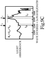
- the glucose concentration is the lowest ( FIG. 9A )
- the light absorption of wavelength ⁇ 1 is taken to be I 10
- the light absorption of wavelength ⁇ 2 is taken to be I 20
- FIG. 9B when the glucose concentration is higher than this
- the light absorption of wavelength ⁇ 1 is taken to be I 11
- the light absorption of wavelength ⁇ 2 is taken to be I 21
- the light absorption of wavelength ⁇ 1 is taken to be I 12
- the light absorption of wavelength ⁇ 2 is taken to be I 22 .
- the characteristics in FIG. 4 and FIG. 5 correspond to the relationship between the light absorption and the blood glucose level of wavelength ⁇ 1 .
- the blood glucose level as described above by using the light intensity of the first diffused reflected light 200A that is detected by the light detector 40A, and the light intensity of the second diffused reflected light 200B that is detected by the light detector 40B.
- the monitoring light detector 16 it is possible to set the monitoring light detector 16 to detect either the first laser light 100A or the second laser light 100B. Both the first laser light 100A and the second laser light 100B are oscillated by using a single OPO 52, so for monitoring (normalizing) the light intensity, either the first laser light 100A or the second laser light 100B can be set to be detected by the monitoring light detector 16.
- the calculation described above can be performed by dividing the monitored laser light by a wavelength selection beam splitter, and using light intensity that is normalized for each wavelength by using a monitoring light detector for each wavelength.
- a first laser light 100A and a second laser light 100B having different wavelengths were simultaneously oscillated from a single light source 50 and used.
- a first diffused reflected light 200A and a second diffused reflected light 200B that are respectively obtained from each of these are divided by using a wavelength selection beam splitter 60, and each is respectively detected by a light detector 40A and 40B.
- configuration can also be such that the first laser light 100A and second laser light 100B pass through a rotatable wavelength selection filter before entering into the incident side optical waveguide.
- the wavelength that passes through the wavelength selection filter can be set to either ⁇ 1 or ⁇ 2 according to the set angle (rotation angle) of the wavelength selection filter, and when the wavelength selection filter is rotated, the first laser light 100A or second laser light 100B is alternately incident on the body epithelium, and according to this, the first diffused reflected light 200A and the second diffused reflected light 200B are alternately switched and outputted.
- the wavelength selection beam splitter 15 described above is not necessary, and as in the configuration illustrated in FIG. 1 , it is possible to respectively detect the light intensity of the first diffused reflected light 200A and the second diffused reflected light 200B by using a single light detector 40, and the blood glucose level can be calculated in the same way as described above.
- the lag between the detection timing for detecting the first diffused reflected light 200A and the second diffused reflected light 200B can be made to be on the order of a millisecond for example.
- the rate of change over time of the blood glucose level is taken into consideration, the degree of this lag is ignorable.
- the wavelength ⁇ 1 having large absorption by glucose can be appropriately selected from an absorption spectrum, and ⁇ 1 can be set from within the range of approximately 7 ⁇ m to approximately 11 ⁇ m, and preferably from within the range of approximately 9.0 ⁇ m to approximately 9.5 ⁇ m (9.26 ⁇ m in the example described above).
- wavelength ⁇ 2 that has small absorption by glucose can also be set in the same way, and in the example described above ⁇ 2 ⁇ ⁇ 1 , however ⁇ 2 > ⁇ 1 is also possible.
- the second laser light 100B is used as a reference, so preferably a wavelength having a large difference in absorption by glucose when compared with the wavelength ⁇ 1 is set as ⁇ 2 .
- ⁇ 1 and ⁇ 2 are preferably both set from a range of wavelengths 2.5 to 12 ⁇ m in the mid-infrared region that can be emitted with high output by an optical parametric oscillator.
- the repetition frequency of the laser light 100 is determined by the repetition frequency of the excitation light source 11.
- a passive Q-switched Yb:YAG laser or a passive Q-switched ND:YAG laser Q-switched Nd:YAG laser
- a Q-switched Yb:YAG laser is preferred.
- this repetition frequency is 1 Hz or greater, and a repetition frequency of approximately 5 Hz to approximately 1 kHz that makes it possible to complete measurement in a short period of time is preferred, and particularly using a repetition frequency of approximately 10 Hz to approximately 100 Hz is preferred.
- the output of the light detector 40 is illustrated for each ⁇ , and by calculating the characteristics in FIG. 4 beforehand for each ⁇ , it is possible to be converted to the glucose concentration.
- ⁇ is determined according to the construction of the light-guiding unit 20.
- a incident-side optical waveguide 21 is not used, as long as it is possible to irradiate laser light 100 having sufficient light intensity on the body epithelium F at an incident angle ⁇ , there is no need to provide an incident side optical waveguide in the light-guiding unit.
- the device for measuring the concentration of substance in blood and method for measuring the concentration of substance in blood can be applied to an arbitrary substance in blood having such characteristics.
- the non-linear optical crystal or excitation light source that is used in the OPO can be selected according to the settings of ⁇ 1 and ⁇ 2 .
- the light source is capable of similarly oscillating pulse shaped excitation light in the OPO, the light source can be similarly used as an excitation light source.
- a CO 2 laser oscillator oscillates laser light having a wavelength that can be adjusted within the range 9.1 to 10.8 ⁇ m according to the setting of the vibration level in transition that contributes to light emission. Therefore, by taking the wavelength ⁇ 1 that has large absorption by glucose to be 9.2 ⁇ m, and the wavelength ⁇ 2 having small absorption by glucose to be 10.2 ⁇ m, for example, it is also possible to alternately oscillate laser light of wavelengths ⁇ 1 and ⁇ 2 .
- a CO 2 laser oscillator when used, by using a high-speed semiconductor switching element, it is possible to repeatedly oscillate laser light having a pulse width of 10 to 50 ns and a rising time and falling time of 10 ns at 1 Hz or greater. When doing this, the spire output of the pulse can be taken to be 10 W to 1 kW. Therefore, it is possible to use a CO 2 laser oscillator instead of the light sources 10, 50 described above.
Landscapes
- Physics & Mathematics (AREA)
- Health & Medical Sciences (AREA)
- Life Sciences & Earth Sciences (AREA)
- Nonlinear Science (AREA)
- Optics & Photonics (AREA)
- Pathology (AREA)
- General Health & Medical Sciences (AREA)
- Veterinary Medicine (AREA)
- Biomedical Technology (AREA)
- Heart & Thoracic Surgery (AREA)
- Medical Informatics (AREA)
- Molecular Biology (AREA)
- Surgery (AREA)
- Animal Behavior & Ethology (AREA)
- Engineering & Computer Science (AREA)
- Biophysics (AREA)
- Public Health (AREA)
- General Physics & Mathematics (AREA)
- Chemical & Material Sciences (AREA)
- Spectroscopy & Molecular Physics (AREA)
- Emergency Medicine (AREA)
- Crystallography & Structural Chemistry (AREA)
- Analytical Chemistry (AREA)
- Biochemistry (AREA)
- Immunology (AREA)
- Measurement Of The Respiration, Hearing Ability, Form, And Blood Characteristics Of Living Organisms (AREA)
- Investigating Or Analysing Materials By Optical Means (AREA)
Claims (22)
- Dispositif (1) pour mesurer la concentration d'une substance dans le sang qui mesure la concentration d'une substance qui est incluse dans le sang d'un corps, incluant :un oscillateur laser (19) qui fait osciller une première lumière laser ayant une longueur d'onde spécifique et qui est absorbée par la substance ;une unité de guidage de lumière (20) qui guide la première lumière laser vers le corps, et qui guide la première lumière réfléchie diffusée qui est générée par la première lumière laser à partir du corps ; etune unité de détection de lumière (40) qui détecte l'intensité lumineuse de la première lumière réfléchie diffusée,la longueur d'onde spécifique de la première lumière laser est sélectionnée dans la plage de 2,5 µm à 12 µm ;dans l'unité de guidage de lumière (20), un guide d'onde optique côté incident qui guide la première lumière laser vers le corps et un guide d'onde optique côté sortie (22) qui guide la première lumière réfléchie diffusée vers l'unité de détection de lumière (40) sont chacun formés comme un trou traversant de manière à pénétrer à travers la même unité de guidage de lumière (20) ; etla première lumière laser est collectée par le guide d'onde optique côté incident qui est formé comme un trou traversant, oùune fenêtre (30) est prévue sur l'unité de guidage de lumière (40) à une position qui, pendant l'utilisation, fait face au corps et est utilisable pour être en contact étroit avec celui-ci lorsque la concentration de la substance est en train d'être mesurée,un côté de la fenêtre utilisable pour venir en contact étroit avec le corps a une section concave ou une section convexe configurée de telle sorte que, lors de l'utilisation, lorsque la fenêtre est en contact étroit avec le corps, un espace à travers lequel la première lumière laser et la première lumière réfléchie diffusée passent est formé entre la fenêtre (30) et le corps,la fenêtre constituée d'un matériau transparent à la lumière infrarouge moyenne.
- Dispositif (1) pour mesurer la concentration d'une substance dans le sang selon la revendication 1, où
l'unité de guidage de lumière (20) guide la première lumière laser vers le corps à un angle d'incidence de 35° à 85°. - Dispositif (1) pour mesurer la concentration d'une substance dans le sang selon la revendication 2, où
l'unité de guidage de lumière (20) guide la première lumière laser vers le corps à un angle d'incidence de 60° à 70°. - Dispositif (1) pour mesurer la concentration d'une substance dans le sang selon la revendication 1 ou la revendication 2, où
l'oscillateur laser (12) est un oscillateur paramétrique optique qui utilise une lumière d'excitation ayant une longueur d'onde qui est différente de la première lumière laser et qui est émise par une source de lumière d'excitation (11), et qui fait osciller la première lumière laser par un premier cristal optique non linéaire. - Dispositif (1) pour mesurer la concentration d'une substance dans le sang selon la revendication 4, où
la source de lumière d'excitation (11) est un laser Nd:YAG à commutation Q passive ou un laser Yb:YAG à commutation Q passive. - Dispositif (1) pour mesurer la concentration d'une substance dans le sang selon la revendication 5, où
la source de lumière d'excitation (11) fait osciller une lumière d'excitation puisée avec une fréquence de répétition de 1 Hz ou supérieure. - Dispositif (1) pour mesurer la concentration d'une substance dans le sang selon la revendication 1 ou la revendication 2, où
l'oscillateur laser (12) est un oscillateur laser au dioxyde de carbone gazeux. - Dispositif (1) pour mesurer la concentration d'une substance dans le sang selon l'une quelconque des revendications 4 à 6, oùl'oscillateur laser (12) fait osciller une deuxième lumière laser ayant une longueur d'onde qui est comprise dans la plage de 2,5 à 12 µm et qui est différente de celle de la première lumière laser, et qui a pour caractéristique d'être moins absorbée par la substance que la première lumière laser ; etdans l'unité de guidage de lumière (20)le guide d'onde optique côté incident (21) guide la deuxième lumière laser vers le corps, et le guide d'onde optique côté sortie (22) guide la deuxième lumière réfléchie diffusée qui est générée par la deuxième lumière laser vers l'unité de détection de lumière (40).
- Dispositif (1) pour mesurer la concentration d'une substance dans le sang selon la revendication 8, où
l'oscillateur paramétrique optique (12) comprend un deuxième cristal optique non linéaire qui génère la deuxième lumière laser à l'aide de la lumière d'excitation. - Dispositif (1) pour mesurer la concentration d'une substance dans le sang selon la revendication 9, où
dans l'oscillateur paramétrique optique (12), le premier cristal optique non linéaire et le deuxième cristal optique non linéaire sont agencés en série sur le trajet optique. - Dispositif (1) pour mesurer la concentration d'une substance dans le sang selon la revendication 7, oùl'oscillateur laser (12) fait osciller une deuxième lumière laser ayant une longueur d'onde comprise dans la plage de 2,5 à 12 µm et qui est différente de celle de la première lumière laser, et qui a pour caractéristique d'être moins absorbée par la substance que la première lumière laser ; etdans l'unité de guidage de lumière (20)le guide d'onde optique côté incident (21) guide la deuxième lumière laser vers le corps, et le guide d'onde optique côté sortie (22) guide la deuxième lumière réfléchie diffusée qui est générée par la deuxième lumière laser vers l'unité de détection de lumière (40).
- Dispositif (1) pour mesurer la concentration d'une substance dans le sang selon la revendication 11, où
l'oscillateur laser (12) fait osciller la première lumière laser et la deuxième lumière laser sous une forme puisée avec une fréquence de répétition de 1 Hz ou supérieure. - Dispositif (1) pour mesurer la concentration d'une substance dans le sang selon l'une quelconque des revendications 1 à 12, oùla substance est le glucose ; etla longueur d'onde de la première lumière laser est comprise dans la plage de 7,0 µm à 11 µm.
- Dispositif (1) pour mesurer la concentration d'une substance dans le sang selon l'une quelconque des revendications 1 à 13, où le guide d'onde optique côté incident (21) est formé de telle sorte qu'un côté sortie du guide d'onde optique côté incident devient progressivement plus étroit qu'un côté incident du guide d'onde optique côté incident (21).
- Procédé pour mesurer la concentration d'une substance dans le sang qui mesure la concentration d'une substance incluse dans le sang d'un corps, etmesure la concentration de la substance dans le fluide interstitiel épithélial du corps par l'intensité lumineuse d'une première lumière réfléchie diffusée qui est générée en irradiant le corps avec une première lumière laser ayant une longueur d'onde spécifique et qui est absorbée par la substance, oùla première lumière laser est guidée vers le corps par un guide d'onde optique côté incident,la première lumière réfléchie diffusée est guidée vers une unité de détection de lumière par un guide d'onde optique côté sortie, l'unité de détection de lumière détectant l'intensité lumineuse,la longueur d'onde spécifique de la première lumière laser est choisie dans la plage de 2,5 µm à 12 µm ;le guide d'onde optique côté incident et le guide d'onde optique côté sortie sont chacun formés comme un trou traversant de manière à pénétrer à travers la même unité de guidage de lumière ; etla première lumière laser est collectée par le guide d'onde optique côté incident qui est formé comme un trou traversant, oùfournissant une fenêtre (30) à l'unité de guidage de lumière (40) à une position telle qu'elle fait face au corps et est en contact étroit avec le corps lorsque la concentration de la substance est en train d'être mesurée,un côté de la fenêtre qui vient en contact étroit avec le corps ayant une section concave ou une section convexe, où, lorsque la fenêtre est en contact étroit avec le corps, un espace à travers lequel la première lumière laser et la première lumière réfléchie diffusée passent est formé entre la fenêtre (30) et le corps, oùla fenêtre (30) constituée d'un matériau transparent à la lumière infrarouge moyenne.
- Procédé pour mesurer la concentration d'une substance dans le sang selon la revendication 15, qui
guide la première lumière laser vers le corps à un angle d'incidence de 35° à 85°. - Procédé pour mesurer la concentration d'une substance dans le sang selon la revendication 16, qui
guide la première lumière laser vers le corps à un angle d'incidence de 60° à 70°. - Procédé pour mesurer la concentration d'une substance dans le sang selon la revendication 15 ou la revendication 16, qui
fait osciller la première lumière laser par oscillation paramétrique optique. - Procédé pour mesurer la concentration d'une substance dans le sang selon la revendication 15 ou la revendication 16, qui
fait osciller la première lumière laser par un oscillateur laser au dioxyde de carbone gazeux. - Procédé pour mesurer la concentration d'une substance dans le sang selon l'une quelconque des revendications 15 à 19, quiirradie le corps avec une deuxième lumière laser ayant une longueur d'onde qui est comprise dans une plage de 2,5 à 12 µm, et qui a pour caractéristique d'être moins absorbée par la substance que la première lumière laser, etmesure la concentration de la substance dans le fluide interstitiel épithélial du corps par l'intensité lumineuse de la première lumière réfléchie diffusée et l'intensité lumineuse de la deuxième lumière réfléchie diffusée qui est générée par la deuxième lumière laser.
- Procédé pour mesurer la concentration d'une substance dans le sang selon la revendication 20, oùle trajet optique de la première lumière laser et le trajet optique de la deuxième lumière laser se chevauchent, etle trajet optique de la première lumière réfléchie diffusée qui est incidente sur une unité de détection de lumière qui détecte l'intensité lumineuse, et le trajet optique de la deuxième lumière réfléchie diffusée qui est incidente sur l'unité de détection de lumière se chevauchent.
- Procédé pour mesurer la concentration d'une substance dans le sang selon l'une quelconque des revendications 15 à 21, oùla substance est le glucose, etla longueur d'onde de la première lumière laser est comprise dans la plage de 7,0 µm à 11 µm.
Applications Claiming Priority (2)
| Application Number | Priority Date | Filing Date | Title |
|---|---|---|---|
| JP2015009504 | 2015-01-21 | ||
| PCT/JP2016/051339 WO2016117520A1 (fr) | 2015-01-21 | 2016-01-19 | Dispositif et procédé pour mesurer la concentration d'une substance dans le sang |
Publications (3)
| Publication Number | Publication Date |
|---|---|
| EP3248544A1 EP3248544A1 (fr) | 2017-11-29 |
| EP3248544A4 EP3248544A4 (fr) | 2018-09-05 |
| EP3248544B1 true EP3248544B1 (fr) | 2021-12-08 |
Family
ID=56417064
Family Applications (1)
| Application Number | Title | Priority Date | Filing Date |
|---|---|---|---|
| EP16740127.2A Active EP3248544B1 (fr) | 2015-01-21 | 2016-01-19 | Dispositif et procédé pour mesurer la concentration d'une substance dans le sang |
Country Status (5)
| Country | Link |
|---|---|
| US (2) | US10806385B2 (fr) |
| EP (1) | EP3248544B1 (fr) |
| JP (3) | JP6415606B2 (fr) |
| CN (1) | CN107427266B (fr) |
| WO (1) | WO2016117520A1 (fr) |
Families Citing this family (30)
| Publication number | Priority date | Publication date | Assignee | Title |
|---|---|---|---|---|
| JP6551898B1 (ja) * | 2017-09-05 | 2019-07-31 | 国立研究開発法人量子科学技術研究開発機構 | レーザー装置、光源および測定装置 |
| EP3477278B1 (fr) * | 2017-10-27 | 2020-04-22 | Humboldt-Universität zu Berlin | Procédé de photoacoustique à une lumière de mesure comprenant une plage de longueurs d'onde prédéterminée permettant la détermination des propriétés d'un échantillon inhomogène |
| WO2019110084A1 (fr) * | 2017-12-04 | 2019-06-13 | Diamontech Gmbh | Dispositif et procédé d'analyse d'une substance |
| WO2019143611A1 (fr) * | 2018-01-16 | 2019-07-25 | The Regents Of The University Of California | Surveillance in-situ du taux de sueur pour la normalisation de concentrations d'analytes de la sueur |
| WO2019216260A1 (fr) | 2018-05-09 | 2019-11-14 | 国立研究開発法人量子科学技術研究開発機構 | Dispositif d'identification de tissu, système d'identification de tissu, procédé d'identification de tissu, procédé d'inspection, système d'endoscope, programme d'identification de tissu et support d'enregistrement |
| CN110514617A (zh) * | 2018-05-22 | 2019-11-29 | 泰科电子(上海)有限公司 | 浓度检测装置、浓度监控装置和太阳能热水器 |
| JP7080480B2 (ja) * | 2018-07-19 | 2022-06-06 | 有限会社ティ・エス・イー | 非侵襲血中糖計測計 |
| CN112351735B (zh) * | 2018-07-20 | 2024-01-30 | 桐生电子开发有限责任公司 | 血糖值变化量测定装置 |
| WO2020121073A1 (fr) * | 2018-12-14 | 2020-06-18 | Ecole Polytechnique Federale De Lausanne (Epfl) | Capteur non effractif du glucose |
| WO2020130571A1 (fr) * | 2018-12-19 | 2020-06-25 | 전자부품연구원 | Dispositif et procédé de test sérologique non invasif |
| KR102727114B1 (ko) * | 2019-02-01 | 2024-11-06 | 현대자동차주식회사 | 비침습적인 광학식 내부 물질 감지기 |
| KR102765475B1 (ko) | 2019-04-10 | 2025-02-07 | 삼성전자주식회사 | 생체정보 추정 장치 및 방법 |
| CN112641443A (zh) * | 2019-10-12 | 2021-04-13 | 潍坊学院 | 一种用于无损检测皮下组织液中葡萄糖的装置 |
| JP7439456B2 (ja) * | 2019-10-28 | 2024-02-28 | 株式会社リコー | 生体情報測定装置、及び生体情報測定方法 |
| US12222288B2 (en) * | 2020-03-04 | 2025-02-11 | Mitsubishi Electric Corporation | Biological component measurement apparatus |
| EP4189366A1 (fr) * | 2020-07-30 | 2023-06-07 | Ricoh Company, Ltd. | Appareil de mesure |
| JP7729075B2 (ja) * | 2020-07-30 | 2025-08-26 | 株式会社リコー | 測定装置 |
| EP4224147A4 (fr) * | 2020-09-30 | 2024-03-13 | Light Touch Technology Incorporated | Dispositif et procédé de mesure de concentration de substance dans le sang |
| CN112683851A (zh) * | 2021-03-22 | 2021-04-20 | 宁波普瑞柏生物技术股份有限公司 | 蛋白浓度检测分析方法、装置及其应用 |
| KR102511907B1 (ko) * | 2021-05-26 | 2023-03-20 | 건국대학교 글로컬산학협력단 | 광학 모듈을 이용한 비침습적 생체물질 당농도 측정 시스템 및 방법 |
| CN113675719A (zh) * | 2021-07-16 | 2021-11-19 | 西安电子科技大学 | 一种可调谐长波中红外超快激光光源装置 |
| JP7541301B2 (ja) * | 2021-08-25 | 2024-08-28 | ライトタッチテクノロジー株式会社 | 血中物質濃度測定装置、血中物質濃度測定方法及びプログラム |
| JP7690355B2 (ja) | 2021-08-27 | 2025-06-10 | 株式会社東芝 | 分析装置 |
| DE102021132135A1 (de) * | 2021-12-07 | 2023-06-07 | OSRAM Opto Semiconductors Gesellschaft mit beschränkter Haftung | Verfahren zum ermitteln einer stoffkonzentration und detektoranorndung |
| DE112022005931B4 (de) * | 2022-02-17 | 2026-01-15 | Mitsubishi Electric Corporation | Vorrichtung zur nichtinvasiven substanzanalyse |
| EP4487116A1 (fr) | 2022-03-01 | 2025-01-08 | Illumina, Inc. | Circuit analogique pour compenser un décalage de polarisation dans un réseau d'amplificateurs |
| WO2023195453A1 (fr) | 2022-04-06 | 2023-10-12 | ライトタッチテクノロジー株式会社 | Dispositif de mesure de concentration de substance dans le sang, procédé de mesure de concentration de substance dans le sang, et programme |
| EP4364660A4 (fr) * | 2022-09-17 | 2025-02-26 | Light Touch Technology Incorporated | Dispositif de mesure de concentration de substance dans le sang, procédé de mesure de concentration de substance dans le sang, et programme |
| JP2024112539A (ja) | 2023-02-08 | 2024-08-21 | 株式会社東芝 | センシングシステム、及び反射光学素子 |
| EP4652930A4 (fr) | 2023-10-11 | 2026-05-20 | Light Touch Tech Incorporated | Dispositif de mesure de concentration de substance sanguine, procédé de mesure de concentration de substance sanguine et programme |
Citations (4)
| Publication number | Priority date | Publication date | Assignee | Title |
|---|---|---|---|---|
| US5370114A (en) * | 1992-03-12 | 1994-12-06 | Wong; Jacob Y. | Non-invasive blood chemistry measurement by stimulated infrared relaxation emission |
| WO2006079797A2 (fr) * | 2005-01-28 | 2006-08-03 | Melys Diagnostics Limited | Dispositif permettant de mesurer la concentration d'un melange a analyser |
| JP2012191969A (ja) * | 2011-03-14 | 2012-10-11 | Shinshu Univ | 生体情報測定装置 |
| US20140131578A1 (en) * | 2012-11-13 | 2014-05-15 | Curtis R. Hruska | Portable spectrometer |
Family Cites Families (42)
| Publication number | Priority date | Publication date | Assignee | Title |
|---|---|---|---|---|
| DE2606991A1 (de) * | 1976-02-20 | 1977-08-25 | Nils Dr Med Kaiser | Geraet zur bestimmung des gehaltes von stoffwechselprodukten im blut |
| JPS5483474A (en) | 1977-12-15 | 1979-07-03 | Citizen Watch Co Ltd | Wristwatch with pulsimeter |
| US4259963A (en) | 1979-07-03 | 1981-04-07 | Albert Huch | Multi-purpose transducer for transcutaneous blood measurements |
| US6040578A (en) | 1996-02-02 | 2000-03-21 | Instrumentation Metrics, Inc. | Method and apparatus for multi-spectral analysis of organic blood analytes in noninvasive infrared spectroscopy |
| US5666956A (en) | 1996-05-20 | 1997-09-16 | Buchert; Janusz Michal | Instrument and method for non-invasive monitoring of human tissue analyte by measuring the body's infrared radiation |
| JPH11178799A (ja) * | 1997-12-22 | 1999-07-06 | Matsushita Electric Works Ltd | 生体表層組織の分析方法及びその装置 |
| CN1117548C (zh) * | 1998-06-09 | 2003-08-13 | 徐州医学院 | 无创血糖测量仪 |
| US6748250B1 (en) | 2001-04-27 | 2004-06-08 | Medoptix, Inc. | Method and system of monitoring a patient |
| EP1422512A1 (fr) | 2001-08-28 | 2004-05-26 | Matsushita Electric Industrial Co., Ltd. | Appareil de mesure d'information sur un composant particulier |
| WO2005004712A1 (fr) * | 2003-07-09 | 2005-01-20 | Glucon Inc. | Glucometre portatif |
| JP4363130B2 (ja) * | 2003-09-04 | 2009-11-11 | パナソニック電工株式会社 | 光学的血糖値測定用ピックアップ |
| JP4362075B2 (ja) * | 2004-02-09 | 2009-11-11 | Hoya株式会社 | 双眼鏡 |
| WO2005107579A1 (fr) * | 2004-05-11 | 2005-11-17 | Koninklijke Philips Electronics N.V. | Tete de mesure destinee a l'analyse non invasive de sang |
| EP1749476A1 (fr) | 2004-05-26 | 2007-02-07 | Matsushita Electric Industrial Co., Ltd. | Element optique pour mesurer des bioinformations et dispositif de mesure de bioinformations |
| EP1754443A4 (fr) | 2004-06-10 | 2008-10-22 | Matsushita Electric Industrial Co Ltd | Instrument de mesure d'informations d'un organisme vivant, élément standard, et procédé pour utiliser l'instrument de mesure d'information d'un organisme vivant |
| JP2008504881A (ja) | 2004-07-01 | 2008-02-21 | ヴィヴォメディカル, インコーポレイテッド | 非侵襲性グルコース測定 |
| EP1785089B1 (fr) | 2004-11-12 | 2010-07-21 | Panasonic Corporation | Element optique de mesure de bioinformation et instrument de mesure de bioinformation utilisant celui-ci |
| CN101184439A (zh) | 2005-06-07 | 2008-05-21 | 欧姆龙健康医疗事业株式会社 | 生物体成分计测传感器 |
| US8140139B2 (en) | 2005-06-14 | 2012-03-20 | Dominion Assets, Llc | Method and apparatus for the non-invasive sensing of glucose in a human subject |
| CN101263388A (zh) | 2005-06-14 | 2008-09-10 | 道明资产公司 | 非侵入性检测人类受检体中葡萄糖的方法和设备 |
| US20060281982A1 (en) | 2005-06-14 | 2006-12-14 | Diasense, Inc. | Method and apparatus for the non-invasive sensing of glucose in a human subject |
| US20070093702A1 (en) * | 2005-10-26 | 2007-04-26 | Skyline Biomedical, Inc. | Apparatus and method for non-invasive and minimally-invasive sensing of parameters relating to blood |
| US7729734B2 (en) * | 2006-03-07 | 2010-06-01 | Andreas Mandelis | Non-invasive biothermophotonic sensor for blood glucose monitoring |
| WO2007141859A1 (fr) * | 2006-06-08 | 2007-12-13 | Omron Healthcare Co., Ltd. | Dispositif de mesure d'un constituant biologique capable de mesurer avec précision de façon non-invasive un constituant biologique |
| DE102006036920B3 (de) | 2006-08-04 | 2007-11-29 | Nirlus Engineering Ag | Verfahren zur Messung der Glukosekonzentration in pulsierendem Blut |
| JP4960040B2 (ja) * | 2006-08-11 | 2012-06-27 | 株式会社アドバンテスト | 光生成装置および該装置を備えたテラヘルツ光生成装置 |
| JP5243719B2 (ja) * | 2006-09-25 | 2013-07-24 | パナソニック株式会社 | 生体信号測定具及びこれを用いた生体信号測定方法 |
| JP2008086705A (ja) | 2006-10-05 | 2008-04-17 | Sanyo Electric Co Ltd | 測定補助材およびそれを用いた光学測定方法 |
| US8417304B2 (en) | 2007-03-20 | 2013-04-09 | Pioneer Corporation | Biological information measuring apparatus |
| WO2008134135A2 (fr) | 2007-03-21 | 2008-11-06 | Lumidigm, Inc. | Biométrie à base de caractéristiques localement cohérentes |
| KR20120000108A (ko) * | 2009-04-07 | 2012-01-03 | 레어 라이트, 인크. | 주변-임계 반사 분광 장치, 시스템, 및 방법 |
| TWI519277B (zh) | 2011-03-15 | 2016-02-01 | 明達醫學科技股份有限公司 | 皮膚光學診斷裝置及其運作方法 |
| JP2012194451A (ja) * | 2011-03-17 | 2012-10-11 | Nec Corp | 光モジュールのロック機構 |
| DE102011051949B4 (de) | 2011-07-19 | 2017-05-18 | Leica Microsystems Cms Gmbh | Wechselvorrichtung für ein Mikroskop |
| CN103096225B (zh) * | 2011-11-03 | 2018-05-18 | 北京美尔斯通科技发展股份有限公司 | 骨传导麦克风 |
| CN202446185U (zh) * | 2012-01-09 | 2012-09-26 | 陈黎敏 | 气压止血带保护衬垫 |
| WO2013105519A1 (fr) * | 2012-01-13 | 2013-07-18 | 独立行政法人放射線医学総合研究所 | Dispositif de détection de substances radioactives, système de visibilité permettant de localiser une source de rayonnement et procédé de détection de substances radioactives |
| WO2014011159A1 (fr) * | 2012-07-10 | 2014-01-16 | Draeger Medical Systems, Inc. | Capteurs médicaux mettant en oeuvre une technique de détection de placement |
| AU2013308186B9 (en) * | 2012-08-30 | 2017-09-21 | Iti Scotland - Scottish Enterprise | Long wavelength infrared detection and imaging with long wavelength infrared source |
| CN202932921U (zh) * | 2012-11-12 | 2013-05-15 | 刘海艳 | 一种检验科用安全防刺伤微量采血器 |
| CN103675266A (zh) * | 2013-11-14 | 2014-03-26 | 成都领御生物技术有限公司 | 一种量子点标记的试条卡 |
| CN104269680A (zh) * | 2014-10-14 | 2015-01-07 | 安徽理工大学 | 一种防触电安全插座 |
-
2016
- 2016-01-19 CN CN201680017373.7A patent/CN107427266B/zh active Active
- 2016-01-19 WO PCT/JP2016/051339 patent/WO2016117520A1/fr not_active Ceased
- 2016-01-19 EP EP16740127.2A patent/EP3248544B1/fr active Active
- 2016-01-19 JP JP2016570633A patent/JP6415606B2/ja active Active
- 2016-01-19 US US15/545,661 patent/US10806385B2/en active Active
-
2018
- 2018-10-02 JP JP2018187388A patent/JP2018199080A/ja active Pending
-
2020
- 2020-09-29 US US17/035,751 patent/US11412963B2/en active Active
- 2020-11-13 JP JP2020189743A patent/JP2021037321A/ja active Pending
Patent Citations (4)
| Publication number | Priority date | Publication date | Assignee | Title |
|---|---|---|---|---|
| US5370114A (en) * | 1992-03-12 | 1994-12-06 | Wong; Jacob Y. | Non-invasive blood chemistry measurement by stimulated infrared relaxation emission |
| WO2006079797A2 (fr) * | 2005-01-28 | 2006-08-03 | Melys Diagnostics Limited | Dispositif permettant de mesurer la concentration d'un melange a analyser |
| JP2012191969A (ja) * | 2011-03-14 | 2012-10-11 | Shinshu Univ | 生体情報測定装置 |
| US20140131578A1 (en) * | 2012-11-13 | 2014-05-15 | Curtis R. Hruska | Portable spectrometer |
Also Published As
| Publication number | Publication date |
|---|---|
| US10806385B2 (en) | 2020-10-20 |
| US11412963B2 (en) | 2022-08-16 |
| JP2021037321A (ja) | 2021-03-11 |
| US20180000386A1 (en) | 2018-01-04 |
| EP3248544A1 (fr) | 2017-11-29 |
| JP2018199080A (ja) | 2018-12-20 |
| CN107427266B (zh) | 2021-12-03 |
| JPWO2016117520A1 (ja) | 2017-10-26 |
| CN107427266A (zh) | 2017-12-01 |
| WO2016117520A1 (fr) | 2016-07-28 |
| EP3248544A4 (fr) | 2018-09-05 |
| JP6415606B2 (ja) | 2018-10-31 |
| US20210038125A1 (en) | 2021-02-11 |
| HK1243902A1 (zh) | 2018-07-27 |
Similar Documents
| Publication | Publication Date | Title |
|---|---|---|
| US11412963B2 (en) | Method for measuring concentration of substance in blood | |
| US10261011B2 (en) | Device and method for analyzing a material | |
| US8452360B2 (en) | System and method for non-invasive photothermal radiometric measurement | |
| RU2489689C2 (ru) | Способ неинвазивного оптического определения температуры среды | |
| EP0160768B1 (fr) | Dispositif spectrophotométrique pour la détermination, par voie non-invasive, de glucose dans les tissus vivants | |
| JP4405469B2 (ja) | 生体情報計測装置 | |
| WO2006079797A2 (fr) | Dispositif permettant de mesurer la concentration d'un melange a analyser | |
| US20130289370A1 (en) | Method and device for detecting a blood glucose level using a electromagnetic wave | |
| US20230355142A1 (en) | Substance-in-blood concentration measurement device and substance-in-blood concentration measurement method | |
| JP3966796B2 (ja) | 血糖測定装置 | |
| GB2489717A (en) | Detection of blood analytes using portable Raman spectroscopy device | |
| US20040225206A1 (en) | Non-invasive analyte measurement device having increased signal to noise ratios | |
| CN101336371B (zh) | 可高精度非侵入地计测生物体成分的生物体成分计测装置 | |
| Liu et al. | Next step of non-invasive glucose monitor by NIR technique from the well controlled measuring condition and results | |
| US12144617B2 (en) | Component measurement device and component measurement method | |
| US20060211926A1 (en) | Non-invasive Raman measurement apparatus with broadband spectral correction | |
| US20050137469A1 (en) | Single detector infrared ATR glucose measurement system | |
| JP2001174405A (ja) | グルコースモニタ及びグルコース濃度の測定方法 | |
| US10441201B2 (en) | Noninvasive mid-infrared in vivo glucose sensor | |
| JP2023029143A (ja) | 無侵襲血糖値測定器 | |
| US20250134421A1 (en) | In-blood substance concentration measurement device, in-blood substance concentration measurement method, and program | |
| HK1243902B (zh) | 血中物质浓度测定装置以及血中物质浓度测定方法 | |
| EP4403107A1 (fr) | Dispositif de mesure de concentration de substance dans le sang, procédé de mesure de concentration de substance dans le sang, et programme | |
| JP7541301B2 (ja) | 血中物質濃度測定装置、血中物質濃度測定方法及びプログラム | |
| Shih et al. | Introduction to spectroscopy for noninvasive glucose sensing |
Legal Events
| Date | Code | Title | Description |
|---|---|---|---|
| STAA | Information on the status of an ep patent application or granted ep patent |
Free format text: STATUS: THE INTERNATIONAL PUBLICATION HAS BEEN MADE |
|
| PUAI | Public reference made under article 153(3) epc to a published international application that has entered the european phase |
Free format text: ORIGINAL CODE: 0009012 |
|
| STAA | Information on the status of an ep patent application or granted ep patent |
Free format text: STATUS: REQUEST FOR EXAMINATION WAS MADE |
|
| 17P | Request for examination filed |
Effective date: 20170717 |
|
| AK | Designated contracting states |
Kind code of ref document: A1 Designated state(s): AL AT BE BG CH CY CZ DE DK EE ES FI FR GB GR HR HU IE IS IT LI LT LU LV MC MK MT NL NO PL PT RO RS SE SI SK SM TR |
|
| AX | Request for extension of the european patent |
Extension state: BA ME |
|
| TPAC | Observations filed by third parties |
Free format text: ORIGINAL CODE: EPIDOSNTIPA |
|
| DAV | Request for validation of the european patent (deleted) | ||
| DAX | Request for extension of the european patent (deleted) | ||
| RIC1 | Information provided on ipc code assigned before grant |
Ipc: A61B 5/1455 20060101AFI20180417BHEP |
|
| A4 | Supplementary search report drawn up and despatched |
Effective date: 20180808 |
|
| RIC1 | Information provided on ipc code assigned before grant |
Ipc: A61B 5/1455 20060101AFI20180802BHEP |
|
| STAA | Information on the status of an ep patent application or granted ep patent |
Free format text: STATUS: EXAMINATION IS IN PROGRESS |
|
| 17Q | First examination report despatched |
Effective date: 20190424 |
|
| GRAP | Despatch of communication of intention to grant a patent |
Free format text: ORIGINAL CODE: EPIDOSNIGR1 |
|
| STAA | Information on the status of an ep patent application or granted ep patent |
Free format text: STATUS: GRANT OF PATENT IS INTENDED |
|
| INTG | Intention to grant announced |
Effective date: 20210622 |
|
| GRAS | Grant fee paid |
Free format text: ORIGINAL CODE: EPIDOSNIGR3 |
|
| GRAA | (expected) grant |
Free format text: ORIGINAL CODE: 0009210 |
|
| STAA | Information on the status of an ep patent application or granted ep patent |
Free format text: STATUS: THE PATENT HAS BEEN GRANTED |
|
| AK | Designated contracting states |
Kind code of ref document: B1 Designated state(s): AL AT BE BG CH CY CZ DE DK EE ES FI FR GB GR HR HU IE IS IT LI LT LU LV MC MK MT NL NO PL PT RO RS SE SI SK SM TR |
|
| RAP3 | Party data changed (applicant data changed or rights of an application transferred) |
Owner name: NATIONAL INSTITUTES FOR QUANTUM SCIENCE AND TECHNOLOGY |
|
| REG | Reference to a national code |
Ref country code: GB Ref legal event code: FG4D |
|
| REG | Reference to a national code |
Ref country code: AT Ref legal event code: REF Ref document number: 1453143 Country of ref document: AT Kind code of ref document: T Effective date: 20211215 Ref country code: CH Ref legal event code: EP |
|
| REG | Reference to a national code |
Ref country code: DE Ref legal event code: R096 Ref document number: 602016067122 Country of ref document: DE |
|
| REG | Reference to a national code |
Ref country code: IE Ref legal event code: FG4D |
|
| REG | Reference to a national code |
Ref country code: LT Ref legal event code: MG9D |
|
| REG | Reference to a national code |
Ref country code: NL Ref legal event code: MP Effective date: 20211208 |
|
| PG25 | Lapsed in a contracting state [announced via postgrant information from national office to epo] |
Ref country code: RS Free format text: LAPSE BECAUSE OF FAILURE TO SUBMIT A TRANSLATION OF THE DESCRIPTION OR TO PAY THE FEE WITHIN THE PRESCRIBED TIME-LIMIT Effective date: 20211208 Ref country code: LT Free format text: LAPSE BECAUSE OF FAILURE TO SUBMIT A TRANSLATION OF THE DESCRIPTION OR TO PAY THE FEE WITHIN THE PRESCRIBED TIME-LIMIT Effective date: 20211208 Ref country code: FI Free format text: LAPSE BECAUSE OF FAILURE TO SUBMIT A TRANSLATION OF THE DESCRIPTION OR TO PAY THE FEE WITHIN THE PRESCRIBED TIME-LIMIT Effective date: 20211208 Ref country code: BG Free format text: LAPSE BECAUSE OF FAILURE TO SUBMIT A TRANSLATION OF THE DESCRIPTION OR TO PAY THE FEE WITHIN THE PRESCRIBED TIME-LIMIT Effective date: 20220308 |
|
| REG | Reference to a national code |
Ref country code: AT Ref legal event code: MK05 Ref document number: 1453143 Country of ref document: AT Kind code of ref document: T Effective date: 20211208 |
|
| PG25 | Lapsed in a contracting state [announced via postgrant information from national office to epo] |
Ref country code: SE Free format text: LAPSE BECAUSE OF FAILURE TO SUBMIT A TRANSLATION OF THE DESCRIPTION OR TO PAY THE FEE WITHIN THE PRESCRIBED TIME-LIMIT Effective date: 20211208 Ref country code: NO Free format text: LAPSE BECAUSE OF FAILURE TO SUBMIT A TRANSLATION OF THE DESCRIPTION OR TO PAY THE FEE WITHIN THE PRESCRIBED TIME-LIMIT Effective date: 20220308 Ref country code: LV Free format text: LAPSE BECAUSE OF FAILURE TO SUBMIT A TRANSLATION OF THE DESCRIPTION OR TO PAY THE FEE WITHIN THE PRESCRIBED TIME-LIMIT Effective date: 20211208 Ref country code: HR Free format text: LAPSE BECAUSE OF FAILURE TO SUBMIT A TRANSLATION OF THE DESCRIPTION OR TO PAY THE FEE WITHIN THE PRESCRIBED TIME-LIMIT Effective date: 20211208 Ref country code: GR Free format text: LAPSE BECAUSE OF FAILURE TO SUBMIT A TRANSLATION OF THE DESCRIPTION OR TO PAY THE FEE WITHIN THE PRESCRIBED TIME-LIMIT Effective date: 20220309 Ref country code: ES Free format text: LAPSE BECAUSE OF FAILURE TO SUBMIT A TRANSLATION OF THE DESCRIPTION OR TO PAY THE FEE WITHIN THE PRESCRIBED TIME-LIMIT Effective date: 20211208 |
|
| PG25 | Lapsed in a contracting state [announced via postgrant information from national office to epo] |
Ref country code: NL Free format text: LAPSE BECAUSE OF FAILURE TO SUBMIT A TRANSLATION OF THE DESCRIPTION OR TO PAY THE FEE WITHIN THE PRESCRIBED TIME-LIMIT Effective date: 20211208 |
|
| PG25 | Lapsed in a contracting state [announced via postgrant information from national office to epo] |
Ref country code: SM Free format text: LAPSE BECAUSE OF FAILURE TO SUBMIT A TRANSLATION OF THE DESCRIPTION OR TO PAY THE FEE WITHIN THE PRESCRIBED TIME-LIMIT Effective date: 20211208 Ref country code: SK Free format text: LAPSE BECAUSE OF FAILURE TO SUBMIT A TRANSLATION OF THE DESCRIPTION OR TO PAY THE FEE WITHIN THE PRESCRIBED TIME-LIMIT Effective date: 20211208 Ref country code: RO Free format text: LAPSE BECAUSE OF FAILURE TO SUBMIT A TRANSLATION OF THE DESCRIPTION OR TO PAY THE FEE WITHIN THE PRESCRIBED TIME-LIMIT Effective date: 20211208 Ref country code: PT Free format text: LAPSE BECAUSE OF FAILURE TO SUBMIT A TRANSLATION OF THE DESCRIPTION OR TO PAY THE FEE WITHIN THE PRESCRIBED TIME-LIMIT Effective date: 20220408 Ref country code: EE Free format text: LAPSE BECAUSE OF FAILURE TO SUBMIT A TRANSLATION OF THE DESCRIPTION OR TO PAY THE FEE WITHIN THE PRESCRIBED TIME-LIMIT Effective date: 20211208 Ref country code: CZ Free format text: LAPSE BECAUSE OF FAILURE TO SUBMIT A TRANSLATION OF THE DESCRIPTION OR TO PAY THE FEE WITHIN THE PRESCRIBED TIME-LIMIT Effective date: 20211208 |
|
| PG25 | Lapsed in a contracting state [announced via postgrant information from national office to epo] |
Ref country code: PL Free format text: LAPSE BECAUSE OF FAILURE TO SUBMIT A TRANSLATION OF THE DESCRIPTION OR TO PAY THE FEE WITHIN THE PRESCRIBED TIME-LIMIT Effective date: 20211208 Ref country code: AT Free format text: LAPSE BECAUSE OF FAILURE TO SUBMIT A TRANSLATION OF THE DESCRIPTION OR TO PAY THE FEE WITHIN THE PRESCRIBED TIME-LIMIT Effective date: 20211208 |
|
| REG | Reference to a national code |
Ref country code: CH Ref legal event code: PL |
|
| REG | Reference to a national code |
Ref country code: DE Ref legal event code: R097 Ref document number: 602016067122 Country of ref document: DE |
|
| PG25 | Lapsed in a contracting state [announced via postgrant information from national office to epo] |
Ref country code: MC Free format text: LAPSE BECAUSE OF FAILURE TO SUBMIT A TRANSLATION OF THE DESCRIPTION OR TO PAY THE FEE WITHIN THE PRESCRIBED TIME-LIMIT Effective date: 20211208 Ref country code: IS Free format text: LAPSE BECAUSE OF FAILURE TO SUBMIT A TRANSLATION OF THE DESCRIPTION OR TO PAY THE FEE WITHIN THE PRESCRIBED TIME-LIMIT Effective date: 20220408 |
|
| REG | Reference to a national code |
Ref country code: BE Ref legal event code: MM Effective date: 20220131 |
|
| PLBE | No opposition filed within time limit |
Free format text: ORIGINAL CODE: 0009261 |
|
| STAA | Information on the status of an ep patent application or granted ep patent |
Free format text: STATUS: NO OPPOSITION FILED WITHIN TIME LIMIT |
|
| PG25 | Lapsed in a contracting state [announced via postgrant information from national office to epo] |
Ref country code: LU Free format text: LAPSE BECAUSE OF NON-PAYMENT OF DUE FEES Effective date: 20220119 Ref country code: DK Free format text: LAPSE BECAUSE OF FAILURE TO SUBMIT A TRANSLATION OF THE DESCRIPTION OR TO PAY THE FEE WITHIN THE PRESCRIBED TIME-LIMIT Effective date: 20211208 Ref country code: AL Free format text: LAPSE BECAUSE OF FAILURE TO SUBMIT A TRANSLATION OF THE DESCRIPTION OR TO PAY THE FEE WITHIN THE PRESCRIBED TIME-LIMIT Effective date: 20211208 |
|
| 26N | No opposition filed |
Effective date: 20220909 |
|
| GBPC | Gb: european patent ceased through non-payment of renewal fee |
Effective date: 20220308 |
|
| PG25 | Lapsed in a contracting state [announced via postgrant information from national office to epo] |
Ref country code: SI Free format text: LAPSE BECAUSE OF FAILURE TO SUBMIT A TRANSLATION OF THE DESCRIPTION OR TO PAY THE FEE WITHIN THE PRESCRIBED TIME-LIMIT Effective date: 20211208 Ref country code: BE Free format text: LAPSE BECAUSE OF NON-PAYMENT OF DUE FEES Effective date: 20220131 |
|
| PG25 | Lapsed in a contracting state [announced via postgrant information from national office to epo] |
Ref country code: LI Free format text: LAPSE BECAUSE OF NON-PAYMENT OF DUE FEES Effective date: 20220131 Ref country code: CH Free format text: LAPSE BECAUSE OF NON-PAYMENT OF DUE FEES Effective date: 20220131 |
|
| PG25 | Lapsed in a contracting state [announced via postgrant information from national office to epo] |
Ref country code: IE Free format text: LAPSE BECAUSE OF NON-PAYMENT OF DUE FEES Effective date: 20220119 Ref country code: GB Free format text: LAPSE BECAUSE OF NON-PAYMENT OF DUE FEES Effective date: 20220308 |
|
| PG25 | Lapsed in a contracting state [announced via postgrant information from national office to epo] |
Ref country code: IT Free format text: LAPSE BECAUSE OF FAILURE TO SUBMIT A TRANSLATION OF THE DESCRIPTION OR TO PAY THE FEE WITHIN THE PRESCRIBED TIME-LIMIT Effective date: 20211208 |
|
| PG25 | Lapsed in a contracting state [announced via postgrant information from national office to epo] |
Ref country code: HU Free format text: LAPSE BECAUSE OF FAILURE TO SUBMIT A TRANSLATION OF THE DESCRIPTION OR TO PAY THE FEE WITHIN THE PRESCRIBED TIME-LIMIT; INVALID AB INITIO Effective date: 20160119 |
|
| PG25 | Lapsed in a contracting state [announced via postgrant information from national office to epo] |
Ref country code: MK Free format text: LAPSE BECAUSE OF FAILURE TO SUBMIT A TRANSLATION OF THE DESCRIPTION OR TO PAY THE FEE WITHIN THE PRESCRIBED TIME-LIMIT Effective date: 20211208 Ref country code: CY Free format text: LAPSE BECAUSE OF FAILURE TO SUBMIT A TRANSLATION OF THE DESCRIPTION OR TO PAY THE FEE WITHIN THE PRESCRIBED TIME-LIMIT Effective date: 20211208 |
|
| PG25 | Lapsed in a contracting state [announced via postgrant information from national office to epo] |
Ref country code: MT Free format text: LAPSE BECAUSE OF FAILURE TO SUBMIT A TRANSLATION OF THE DESCRIPTION OR TO PAY THE FEE WITHIN THE PRESCRIBED TIME-LIMIT Effective date: 20211208 |
|
| PG25 | Lapsed in a contracting state [announced via postgrant information from national office to epo] |
Ref country code: TR Free format text: LAPSE BECAUSE OF FAILURE TO SUBMIT A TRANSLATION OF THE DESCRIPTION OR TO PAY THE FEE WITHIN THE PRESCRIBED TIME-LIMIT Effective date: 20211208 |
|
| PGFP | Annual fee paid to national office [announced via postgrant information from national office to epo] |
Ref country code: FR Payment date: 20251222 Year of fee payment: 11 |
|
| PGFP | Annual fee paid to national office [announced via postgrant information from national office to epo] |
Ref country code: DE Payment date: 20251224 Year of fee payment: 11 |